EP2222445B1 - Router table with mechanical drive - Google Patents
Router table with mechanical drive Download PDFInfo
- Publication number
- EP2222445B1 EP2222445B1 EP08797016.6A EP08797016A EP2222445B1 EP 2222445 B1 EP2222445 B1 EP 2222445B1 EP 08797016 A EP08797016 A EP 08797016A EP 2222445 B1 EP2222445 B1 EP 2222445B1
- Authority
- EP
- European Patent Office
- Prior art keywords
- router
- bit
- drive
- table top
- mount
- Prior art date
- Legal status (The legal status is an assumption and is not a legal conclusion. Google has not performed a legal analysis and makes no representation as to the accuracy of the status listed.)
- Not-in-force
Links
- 230000008878 coupling Effects 0.000 claims description 36
- 238000010168 coupling process Methods 0.000 claims description 36
- 238000005859 coupling reaction Methods 0.000 claims description 36
- 230000007246 mechanism Effects 0.000 description 11
- 238000000034 method Methods 0.000 description 4
- 238000005096 rolling process Methods 0.000 description 4
- 238000009434 installation Methods 0.000 description 2
- 230000013011 mating Effects 0.000 description 2
- 230000004308 accommodation Effects 0.000 description 1
- 239000000919 ceramic Substances 0.000 description 1
- 238000003754 machining Methods 0.000 description 1
- 239000000463 material Substances 0.000 description 1
- 239000007787 solid Substances 0.000 description 1
Images




Classifications
-
- B—PERFORMING OPERATIONS; TRANSPORTING
- B27—WORKING OR PRESERVING WOOD OR SIMILAR MATERIAL; NAILING OR STAPLING MACHINES IN GENERAL
- B27C—PLANING, DRILLING, MILLING, TURNING OR UNIVERSAL MACHINES FOR WOOD OR SIMILAR MATERIAL
- B27C9/00—Multi-purpose machines; Universal machines; Equipment therefor
- B27C9/02—Multi-purpose machines; Universal machines; Equipment therefor with a single working spindle
-
- B—PERFORMING OPERATIONS; TRANSPORTING
- B25—HAND TOOLS; PORTABLE POWER-DRIVEN TOOLS; MANIPULATORS
- B25H—WORKSHOP EQUIPMENT, e.g. FOR MARKING-OUT WORK; STORAGE MEANS FOR WORKSHOPS
- B25H1/00—Work benches; Portable stands or supports for positioning portable tools or work to be operated on thereby
- B25H1/0021—Stands, supports or guiding devices for positioning portable tools or for securing them to the work
- B25H1/0042—Stands
- B25H1/005—Stands attached to a workbench
-
- B—PERFORMING OPERATIONS; TRANSPORTING
- B27—WORKING OR PRESERVING WOOD OR SIMILAR MATERIAL; NAILING OR STAPLING MACHINES IN GENERAL
- B27C—PLANING, DRILLING, MILLING, TURNING OR UNIVERSAL MACHINES FOR WOOD OR SIMILAR MATERIAL
- B27C5/00—Machines designed for producing special profiles or shaped work, e.g. by rotary cutters; Equipment therefor
- B27C5/02—Machines with table
-
- B—PERFORMING OPERATIONS; TRANSPORTING
- B27—WORKING OR PRESERVING WOOD OR SIMILAR MATERIAL; NAILING OR STAPLING MACHINES IN GENERAL
- B27C—PLANING, DRILLING, MILLING, TURNING OR UNIVERSAL MACHINES FOR WOOD OR SIMILAR MATERIAL
- B27C5/00—Machines designed for producing special profiles or shaped work, e.g. by rotary cutters; Equipment therefor
- B27C5/10—Portable hand-operated wood-milling machines; Routers
Definitions
- the present disclosure relates to a router table according to the preamble of claim 1.
- a router table is known from document FR1098032 A1 .
- Routers are used for a variety of material working purposes (e.g., woodworking) including finishing work for furniture and cabinets as well as functional connections made of complimentary shaped profiles such as tongue and groove joints, etc.
- Routers typically are of two types: router tables in which the workpiece is moved relative to a stationary router and portable routers that are moved along the workpiece.
- Portable routers typically comprise a pneumatic or electric motor that is located in a housing.
- the housing moves axially along a base.
- An exemplary prior art router 10 is shown in FIG. 8 .
- the router 10 includes router bit 12 attached to the router 10 by a chuck 14.
- a collet may alternatively be used.
- the chuck 14 extends from a drive shaft 16 of motor 18 and is positioned perpendicular to face 20 of base 22 such that the face 20 of the base 22 is translated along a surface 24 of work piece 26 with the bit 12 extending from the face 20 to perform the work on the work piece 26.
- the bit 12 may include a pilot that rides against a shoulder 30 of the work piece 26 to control the cut.
- An example of a portable router is more fully described in US Design Patent No. D 538,614 to Aglassinger , the disclosure of which is incorporated by reference in its entirety.
- Router tables utilize a router bit that extends upwardly above the top of the table.
- the router bit is stationary and is positioned in alignment with a longitudinally extending fence. The workpiece is advanced from right to left along the top of the table, along the fence, and into the router bit to perform the work.
- the router bit may be powered by a dedicated motor positioned under the table.
- the router bit may be powered by a portable router positioned under the table with the router bit extending upwardly through the table.
- An example of a table utilizing a dedicated motor is more fully described in US Patent No. 4,537,234 to Onsrud , the disclosure of which is incorporated by reference in its entirety.
- An example of a table utilizing a portable router is Bosch model is RA1171 Router Table sold by Robert Bosch GmbH, Stuttgart, Germany.
- Routers vary is size, power and weight. Routers used for router tables may have a power capacity of up to three and one-half horsepower, and these routers tend to be very large and heavy. Accordingly, the installation and removal of these routers from the underside of a table may involve significant effort.
- a router table comprises a table top, a bit mount, and a drive train.
- the bit mount is configured to hold a router bit such that the router bit extends from the table top defining a bit axis.
- the drive train is operably connected between the bit mount and a drive coupling.
- the drive coupling is configured to engage a driven member that is driven by a power source.
- the drive coupling defines a drive axis that is not coaxial with the bit axis. Rotation of the driven member and associated drive coupling operates the drive train and results in rotation of the bit mount and associated router bit.
- a table router comprises a table top including a substantially planar upper surface.
- a router bit extends outward from the substantially planar upper surface of the table top.
- a portable router with a rotatable drive shaft is seated on the substantially planar upper surface of the table top.
- a drive train is positioned beneath the table top and operably connects a driven member on the portable router to the router bit. The drive train is configured to rotate the router bit when the drive shaft of the portable router is rotated.
- the router table with mechanical drive provides for a method of driving a router bit on a router table.
- the method comprises positioning the router bit on a bit mount such that the router bit extends away from an upper surface of a table top.
- the method further comprises seating a portable router on the upper surface of the table top such that a driven member on the portable router is operably connected to a drive train positioned under the table top.
- the method comprises rotating the driven member on the portable router in order to operate the drive train and rotate the router bit in the bit mount.
- a routing kit that may be used to shape workpieces with a selectable one of a stationary workpiece and with a moveable workpiece.
- the routing kit includes a router bit, a portable router, a table, a router bit mount, and a drive.
- the portable router has a portable router connector for receiving the router bit.
- the table connects to the portable router.
- the portable router connector of the portable router has a portable router axis of rotation when secured to the table.
- the router bit mount has a rotating portion including a router bit connector for securing the router bit to the router bit mount.
- the rotating portion of the router bit mount has a router bit mount axis of rotation.
- the router bit mount axis of rotation is spaced from the portable router axis of rotation when the portable router is secured to the table.
- the drive connects the portable router connector to the rotating portion of the router bit mount.
- a router table 100 is shown.
- the router table 100 includes a table top 110, a router bit mount 102, a drive coupling 103, and a drive train 104 connected between the router bit mount 102 and the drive coupling 103.
- the router table 100 is configured for use with router bit 106 and a portable router 108.
- the router table 100 is configured to permit an operator to utilize the portable router 108 to serve as a power source for a router table.
- the router table 100 includes a table top 110 and a frame 111 supporting the table top.
- the frame 111 may include legs, feet, side panels, or any other structural members desired for supporting the table top 110.
- the table top 110 includes a substantially planar upper surface 126 which allows the user to slide a working piece across the table top.
- the table top 110 includes two holes including a drive hole 105 and a bit hole 107.
- a driven member 112 of the portable router is configured to fit within the drive hole 105 and a router bit 106 is configured to fit within the bit hole 107.
- the table top 110 may be any of numerous shapes, such as for example, the generally rectangular shape shown in FIG. 1 .
- the table top 110 may further include a peninsula 115 provided at a corner portion, the peninsula being designed to seat the portable router 108 or other power source.
- the portable router 108 includes two handles 119, allowing a user to grasp the portable router 108 in his or her hands and maneuver the router 108.
- the portable router 108 further comprises a rotating drive shaft 116 that is connected to a chuck 114 or other attachment member of the portable router 108.
- the drive shaft 116 defines a portable router axis of rotation 117.
- a driven member 112 is connected to the chuck 114 such that rotation of the drive shaft 116 results in rotation of the driven member 112.
- the driven member is configured to fit within a drive hole 105 on the table top and join to the drive coupling 103.
- FIG. 2 shows a plan view of the router table 100 including the drive coupling 103 and the bit mount 102 connected by the drive train 104.
- the drive train 104 includes a belt 136 connected between a drive pulley 123 and a bit pulley 125.
- the drive pulley 123 is connected to the drive coupling 103 and the bit pulley 125 is connected to the bit mount 102.
- the belt 136 translates rotation of the drive coupling 103 and the associated drive pulley 123 into rotation of the bit pulley 125 and the associated bit mount. While a belt 136 and pulleys 123, 125 have been shown in the embodiment of FIG.
- the drive train 104 may comprise a chain or a plurality of cooperating gears, or any appropriate combination of these or other drive train members as will be recognized by those in the art.
- FIG. 3 shows an elevation view of the table top 110 of the router table 100 with the portable router 108 positioned on the table top 110.
- the driven member 112 which is connected to the portable router via chuck 114 extends through the hole 105 in the table top 110 and is connected to drive coupling 103.
- drive coupling 103 may be provided in any of various forms to join the drive bit 112 to the drive coupling 103.
- the drive bit 112 may be provided in the form of a chuck or collet.
- drive coupling 103 may be provided as a shaped hole (e.g., a square hole) formed in a rotating member, and the drive bit 112 may be provided as a complimentary shaped rod that extends into the hole.
- the rotatable drive coupling 103 defines a drive axis 117A about which the drive shaft 116 of the router 108 and the drive bit 112 rotate when the drive bit 112 is positioned in the bit coupling 103.
- the rotatable drive coupling 103 is secured in place with a support 133 that is connected to the under side of the table top 110.
- the support 133 allows the drive coupling 103 to rotate about the drive axis 117A, but retains the drive coupling 103 in place relative to the table top 110.
- the rotatable drive coupling 103 is connected to the rotatable drive pulley 123.
- the belt 123 extends between the drive pulley 123 and the rotatable bit pulley 125.
- the bit pulley 125 is connected to the bit mount 102.
- the router bit mount 102 includes a rotatable extended portion 118 that is configured to extend through the bit hole 107 in the table top 110.
- the extended portion 118 of the router bit mount 102 may comprise a chuck or collet or other appropriate connector used to secure the router bit 106 to the bit mount 102.
- the extended portion 118 is connected to the drive train 104 via the bit pulley 125.
- the extended portion is held in place relative to the underside of the table top 110 using a support 135.
- the support 135 allows the extended portion 118 to rotate about bit axis 127, while securing the extended portion in place relative to the table top 110.
- the portable router 108 is removably secured to table top 110.
- the portable router 108 may include bottom surface 122 of base 124 of the portable router 108.
- the bottom surface 122 of the base 124 of the router 108 may rest on the upper planar surface 126 of the table top 110.
- the router axis or rotation 117 is coaxial with the drive coupling axis of rotation 117A.
- the drive coupling axis 117A is parallel with the bit axis 127, but they are not coaxial. Instead, the drive coupling axis 117A is spaced apart from the bit axis 127 on the table top 110.
- the table top 110 may include a seat in the form of a bracket 128 or other mechanism for securing the portable router 108 to the table top 110.
- the seat 128 may, as shown in Figure 3A , be in the form of a vertical wall 130 having a shape conforming to that of base 124 of the router 108.
- the seat 128 may include clamps 132 positioned over upper surface 134 of the base 124 of the router 108.
- numerous other seat arrangements may be possible as will be recognized by those of skill in the art.
- the chuck/rotating portion 114 of the router 108 typically rotates, when viewed from above, clockwise in the direction of arrow 142.
- An operator 144 when machining work piece 146 on router table 113 typically advances the work piece 146 from right to left in the direction of arrow 148 into router 106 to perform work on the work piece 146.
- the movement of the work piece 146 in the direction of arrows 148 from right to left is typical when using currently available router tables.
- This motion of work flow is very common to operators 144 and, as such, the router table 100 may be configured such that the operator 144 may utilize the router table 100 by moving the work piece 146 in the direction of arrows 148.
- the rotating portion 118 of the router bit mount 102 rotates in a counterclockwise direction as shown in arrows 150.
- the direction of rotation of the rotating portion 114 of the portable router 108 as shown by arrows 142 and the direction of the rotating portion 118 of the router bit mount 102 as shown by arrows 150 are opposite. Accommodation of the reversed rotation of the rotating portion 118 of mount 102 with respect to the rotating portion 114 of the portable router 108 requires that the drive train 104 reverse the rotation of the components from input to output.
- the drive train 104 of the router table 100 of the embodiment of FIG. 4 includes a router spindle or an intermediate spindle 152.
- An intermediate pulley 154 is mounted onto intermediate spindle 152.
- the belt 136 connects intermediate pulley 154 and to router bit mount pulley 156 mounted on router bit mount 102.
- the intermediate spindle 152 may be connected to the rotating portion 114 of the portable router 108 by any suitable manner.
- the rotating portion 114 of the portable router 108 includes a drive gear 158 which mates with a driven gear 160 mounted onto intermediate spindle 152.
- the belt 136 may be replaced by a chain 138 that connects the intermediate pulley 154 and to router bit mount pulley 156.
- a chain 138 that connects the intermediate pulley 154 and to router bit mount pulley 156.
- the mechanism of the present disclosure may be in the form of router table 100A which includes a rotating portion 114A of portable router 108A including a pulley 154A which is connected by belt 156A to idler pulley 158A.
- the external surface 160A of the belt 156A may contact outer surface 162A of belt 164A connected between intermediate pulley 166A and router bit mount pulley 168A.
- the mechanism of the present disclosure may be in the form of router table 100B which includes a belt 136B positioned between idler pulley 154B and router bit mount pulley 156B.
- the periphery of idler pulley 154B may be connected to a frictional drive in the form of rubber wheel 158B that is also connected to rotating portion 114B of portable router 108B.
- the mechanism of the present disclosure may be in the form of router table 100C that includes drive train 104C having a belt 136C which is crossed or has a figure 8 shape.
- the figure 8 -shaped belt 136C is connected to portable router pulley 158C and to router bit mount pulley 156C.
- the use of the figure 8 -shaped belt 136C obviates the need for an intermediate spindle and intermediate drive trains.
- the router table 100D includes a rotating portion 114D of portable router 108D.
- a drive pulley 154D is connected to the rotating portion 114D.
- the drive pulley 154D is used to drive a belt 136D which wraps around an idler pulley 158D and a bit mount pulley 156D, the bit mount pulley 156D being operably connected to the router bit mount quill 178 and the router bit 106.
- the belt 136D may be a double-sided belt having different configurations in different embodiments.
- the belt 136D may be a double sided v-type belt in one embodiment and a tooth-type belt in another embodiment.
- the external surface 160D of the belt 136D contacts the drive pulley 154D and the inner surface 161 D of the belt 136D contacts the idler pulley 158D and the bit mount pulley 156D.
- the configuration of the drive train of FIGs. 4D-4E allows the bit mount pulley 156D to rotate in an opposite direction from the drive pulley 154D. Also, in the embodiment of FIGs. 4D and 4E , the position of the idler pulley 158D may be adjusted in order to set the belt tension.
- the intermediate spindle 152 may be connected to the rotating portion 114 of the portable router 108 in any suitable manner.
- the rotating portion 114 of the portable router 108 includes drive gear 158 which mates with driven gear 160 mounted to intermediate spindle 152.
- the belt 136 connects intermediate pulley 154 to router bit mount pulley 156.
- the intermediate pulley 154 and the router bit mount pulley 156 are fixed at their rotating axes.
- the rotating portion 118 of the router bit mount 102 may be fixed in a vertical direction. If fixed in a vertical direction, the rotating portion 118 of the router bit mount 102 does not accommodate a vertical adjustment of the router bit 106.
- the router bit mount 102 may include a router bit mount chuck 174 which may permit shaft 176 and router bit 106 to be positioned in various vertical heights with respect to the chuck 174.
- the router bit mount may include an internally threaded portion and an externally threaded portion (not shown) that may be adjusted vertically.
- the router bit mount 102 may include a quill 178 for permitting the movement of the router bit 106 in the vertical direction.
- the quill 178 may be any commercially available quill such as those described in U.S. Patent 2,072,646 to Cenasek or U.S. Patent No. 3,609,055 to Luff , the disclosure of both patents being hereby incorporated by reference in their entireties.
- the intermediate pulley 154 and the router bit mount pulley 156 may be standard pulleys and may be flat or V-type pulleys corresponding to a flat or a V-type belt 136, respectively.
- the diameter DI of the intermediate pulley 154 may be the same as the diameter DM of the router bit mount pulley 156. If the diameters DI and DM are equal, the rotational speed of the intermediate spindle 152 and the rotating portion 118 of the router bit mount 102 will be the same.
- the drive gear 158 has a drive gear diameter RGD while the driven gear 160 has a driven gear diameter SGD. If the diameters RGD and SGD are the same, then the rotational speed of the rotating portion 114 of the portable router 108 will be the same as that of the intermediate spindle 152.
- the gears 158 and 160 and the pulleys 154 and 156 may by identical to each other and may have the same diameter.
- the rotational speed of the rotating portion 118 of the router bit mount 102 may be similar to the rotational speed of the portable router 108. It should be appreciated that, however, the rotating portion 118 of the router bit mount 102 may be selected to be of a higher speed or a lower speed than that of the portable router 108. Therefore, the gears 158 and 160 may have different sizes and the pulleys 154 and 156 may, similarly, have different sizes.
- the pulleys 154 and 156 may be in the form of a variable speed drive.
- a variable speed drive is, for example, shown in U.S. Patent 3,718,405 to Kiter , the disclosure of which is incorporated by reference in its entirety.
- the portable routers 108 typically have a rotational speed of around 25,000 revolutions per minute and may have a power of, for example, three and one half (3.5) horsepower. Therefore, the selection of bearings to support the rotation of the intermediate spindle 152 and the rotational portion 118 of the router bit mounting 102 should be selected to accommodate a high rotational speed.
- the bearings for the drive train 104 of the router table 100 may include air bearings, rolling elements bearings, or journal bearings. If rolling element bearings are utilized, the cages or retainers may be made of a plastic and the rolling elements of the bearing may be preloaded. Also, the bearing rolling elements may be ceramic to permit higher rotational speeds.
- the quill 178 may include a translating portion 180 having external teeth 182 and a rotating portion 184 having mating teeth 186.
- the portion with the mating teeth 186 may include a crank 188 for raising and lowering the router bit 106 in the quill 178 along bit axis 127, as indicated by arrow 185.
- the quill 178 may include a lock 190 to hold the translating portion 180 of the quill 178 in position and a scale or indicia 192 with marks corresponding to selected heights of the various vertical positions of the router bit 106.
- FIG. 6A shows a bottom view of the table top 110 and bit mount 102.
- the crank 188 of the quill 178 includes a crank arm 189 and a knob 191.
- the knob 191 is rotatably supported by the frame 111.
- the knob 191 is connected to the crank arm 189 such that rotation of the knob 191 results in rotation of the crank arm 188. Accordingly, this embodiment of the quill allows a user to adjust the vertical height of the bit 106 relative to the table top 110 using the knob positioned on the frame 111.
- Mechanism 200 is similar to the router table 100 of FIGS. 1-6 , but includes a router bit 206 that has a shape that is the mirror image of the router bit 106.
- the router bit 206 is shown in greater detail in FIG. 7A .
- the use of the mirror image shaped router bit 206 permits successful cutting by the router bit 206 with the router table 212 when the workpiece 246 is advanced from left to right in the direction of arrow 249.
- the use of the router bit 206 permits the utilization of a drive 204 that includes a drive pulley 254 connected by a belt 236 to a mount pulley 256.
- the drive 204 is substantially simpler than the drive 104. It should be appreciated that, however, the utilization of unique mirror image shaped router bits 206 may not be desired.
- the router table 100 may be provided as a plurality of individual members that are sold separately or as a kit that is sold with a plurality of members.
- the routing table 100 kit provides an operator the ability to choose to shape workpieces with either (i) a stationary workpiece and a translating bit using the portable router 108, or (ii) a moveable workpiece and a rotating, non-translating bit, using the router table 113.
- a router table comprises a table top including a substantially planar upper surface; a router bit extending outward from the substantially planar upper surface of the table top; and a portable router seated on the substantially planar upper surface of the table top, the portable router including a rotatable drive shaft; and a drive mechanism positioned beneath the table top, the drive mechanism configured to rotate the router bit when the drive shaft of the portable router is rotated.
- the router bit is seated in a bit mount that is connected to the router table under the table top, the bit mount including a portion that extends through a hole in the table top.
- the router table further comprises a drive coupling operably connecting the portable router to the drive mechanism, and wherein the rotatable drive shaft of the portable router is operably connected to a drive bit that is joined to the drive coupling.
- the drive bit extends through a drive hole in the table top.
Landscapes
- Life Sciences & Earth Sciences (AREA)
- Engineering & Computer Science (AREA)
- Mechanical Engineering (AREA)
- Wood Science & Technology (AREA)
- Forests & Forestry (AREA)
- Milling, Drilling, And Turning Of Wood (AREA)
Description
- The present disclosure relates to a router table according to the preamble of claim 1. Such a router table is known from document
FR1098032 A1 - Routers are used for a variety of material working purposes (e.g., woodworking) including finishing work for furniture and cabinets as well as functional connections made of complimentary shaped profiles such as tongue and groove joints, etc.
- Routers typically are of two types: router tables in which the workpiece is moved relative to a stationary router and portable routers that are moved along the workpiece.
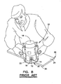
- Portable routers typically comprise a pneumatic or electric motor that is located in a housing. The housing moves axially along a base. An exemplary
prior art router 10 is shown inFIG. 8 . Therouter 10 includesrouter bit 12 attached to therouter 10 by achuck 14. A collet may alternatively be used. Thechuck 14 extends from adrive shaft 16 ofmotor 18 and is positioned perpendicular toface 20 ofbase 22 such that theface 20 of thebase 22 is translated along asurface 24 ofwork piece 26 with thebit 12 extending from theface 20 to perform the work on thework piece 26. Thebit 12 may include a pilot that rides against ashoulder 30 of thework piece 26 to control the cut. An example of a portable router is more fully described inUS Design Patent No. D 538,614 to Aglassinger , the disclosure of which is incorporated by reference in its entirety. - Router tables utilize a router bit that extends upwardly above the top of the table. The router bit is stationary and is positioned in alignment with a longitudinally extending fence. The workpiece is advanced from right to left along the top of the table, along the fence, and into the router bit to perform the work. The router bit may be powered by a dedicated motor positioned under the table. Alternatively, the router bit may be powered by a portable router positioned under the table with the router bit extending upwardly through the table. An example of a table utilizing a dedicated motor is more fully described in
US Patent No. 4,537,234 to Onsrud , the disclosure of which is incorporated by reference in its entirety. An example of a table utilizing a portable router is Bosch model is RA1171 Router Table sold by Robert Bosch GmbH, Stuttgart, Germany. - Routers vary is size, power and weight. Routers used for router tables may have a power capacity of up to three and one-half horsepower, and these routers tend to be very large and heavy. Accordingly, the installation and removal of these routers from the underside of a table may involve significant effort.
- In view of the foregoing, it would be advantageous to provide a router table that provides for easy installation and removal of a router to and from a table. It would also be advantageous if the router could be used for other tasks once removed from the router table.
- In accordance with at least one embodiment of a router table with mechanical drive train, a router table comprises a table top, a bit mount, and a drive train. The bit mount is configured to hold a router bit such that the router bit extends from the table top defining a bit axis. The drive train is operably connected between the bit mount and a drive coupling. The drive coupling is configured to engage a driven member that is driven by a power source. The drive coupling defines a drive axis that is not coaxial with the bit axis. Rotation of the driven member and associated drive coupling operates the drive train and results in rotation of the bit mount and associated router bit.
- According to the invention, a table router comprises a table top including a substantially planar upper surface. A router bit extends outward from the substantially planar upper surface of the table top. A portable router with a rotatable drive shaft is seated on the substantially planar upper surface of the table top. A drive train is positioned beneath the table top and operably connects a driven member on the portable router to the router bit. The drive train is configured to rotate the router bit when the drive shaft of the portable router is rotated.
- The router table with mechanical drive provides for a method of driving a router bit on a router table. The method comprises positioning the router bit on a bit mount such that the router bit extends away from an upper surface of a table top. The method further comprises seating a portable router on the upper surface of the table top such that a driven member on the portable router is operably connected to a drive train positioned under the table top. In addition, the method comprises rotating the driven member on the portable router in order to operate the drive train and rotate the router bit in the bit mount.
- Pursuant to another embodiment, there is provided a routing kit that may be used to shape workpieces with a selectable one of a stationary workpiece and with a moveable workpiece. The routing kit includes a router bit, a portable router, a table, a router bit mount, and a drive. The portable router has a portable router connector for receiving the router bit. The table connects to the portable router. The portable router connector of the portable router has a portable router axis of rotation when secured to the table. The router bit mount has a rotating portion including a router bit connector for securing the router bit to the router bit mount. The rotating portion of the router bit mount has a router bit mount axis of rotation. The router bit mount axis of rotation is spaced from the portable router axis of rotation when the portable router is secured to the table. The drive connects the portable router connector to the rotating portion of the router bit mount.
- While it would be desirable to provide a router table that provides this or other advantageous features as may be apparent to those reviewing this disclosure, the teachings disclosed herein extend to those embodiments which fall within the scope of the appended claims, regardless of whether they accomplish the above-mentioned or other advantages.
-
-
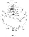
FIG. 1 is a perspective view of a router table with mechanical drive configured for use with a portable router positioned on a table top; -
FIG. 2 is a plan view of the router table ofFIG. 1 showing a drive train of the router table; -
FIG. 3 is an elevation view of the router table ofFIG. 1 with a front panel removed to show the components positioned above and below the table top; -
FIG. 3A is a partial top view of the routing table ofFIG. 1 showing a bracket to hold the portable router on the table top; -
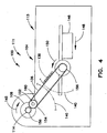
FIG. 4 is a partially cutaway top view of one embodiment of the router table ofFIG. 1 showing the drive in greater detail; -
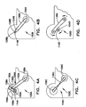
FIG. 4A is a cutaway partial top view of the router table ofFIG. 4 with an alternate drive configuration; -
FIG. 4B is a cutaway partial top view of the router table ofFIG. 4 with another alternate drive configuration; -
FIG. 4C is a cutaway partial top view of a router table ofFIG. 4 with yet another alternate drive configuration; -
FIG. 4D is a cutaway partial top view of a router table ofFIG. 4 with yet another alternate drive configuration; -
FIG. 4E is a perspective view of the drive configuration ofFIG. 4D with the table top of the router table omitted; -
FIG. 5 is a partially cutaway elevation view of the router table ofFIG. 1 showing an embodiment of the drive train in even greater detail; -
FIG. 6 is a partial cross-sectional view of the router table ofFIG. 1 showing a router bit mount in greater detail; -
FIG. 6A is a bottom view of the router table ofFIG. 1 showing the adjustment mechanism for the router bit mount in further detail; -
FIG. 7 is a top partially cutaway view of an alternate routing kit for use with router bits; -
FIG. 7A is a perspective view of a mirror image router bit; and -
FIG. 8 is a perspective view of a prior art portable router. - Corresponding reference characters indicate corresponding parts throughout the several views. Like reference characters indicate like parts throughout the several views.
- According to an embodiment of the present disclosure and referring to
FIGs. 1-3 , a router table 100 is shown. The router table 100 includes atable top 110, arouter bit mount 102, adrive coupling 103, and adrive train 104 connected between therouter bit mount 102 and thedrive coupling 103. The router table 100 is configured for use withrouter bit 106 and aportable router 108. The router table 100 is configured to permit an operator to utilize theportable router 108 to serve as a power source for a router table. - As shown in
FIG. 1 , the router table 100 includes atable top 110 and aframe 111 supporting the table top. Theframe 111 may include legs, feet, side panels, or any other structural members desired for supporting thetable top 110. Thetable top 110 includes a substantially planarupper surface 126 which allows the user to slide a working piece across the table top. Thetable top 110 includes two holes including adrive hole 105 and abit hole 107. As explained in further detail below, a drivenmember 112 of the portable router is configured to fit within thedrive hole 105 and arouter bit 106 is configured to fit within thebit hole 107. Thetable top 110 may be any of numerous shapes, such as for example, the generally rectangular shape shown inFIG. 1 . Thetable top 110 may further include apeninsula 115 provided at a corner portion, the peninsula being designed to seat theportable router 108 or other power source. - As shown in
FIG. 1 , theportable router 108 includes twohandles 119, allowing a user to grasp theportable router 108 in his or her hands and maneuver therouter 108. Theportable router 108 further comprises arotating drive shaft 116 that is connected to achuck 114 or other attachment member of theportable router 108. Thedrive shaft 116 defines a portable router axis ofrotation 117. A drivenmember 112 is connected to thechuck 114 such that rotation of thedrive shaft 116 results in rotation of the drivenmember 112. The driven member is configured to fit within adrive hole 105 on the table top and join to thedrive coupling 103. -
FIG. 2 shows a plan view of the router table 100 including thedrive coupling 103 and thebit mount 102 connected by thedrive train 104. In the embodiment ofFIG. 2 , thedrive train 104 includes abelt 136 connected between adrive pulley 123 and abit pulley 125. Thedrive pulley 123 is connected to thedrive coupling 103 and thebit pulley 125 is connected to thebit mount 102. Thebelt 136 translates rotation of thedrive coupling 103 and the associateddrive pulley 123 into rotation of thebit pulley 125 and the associated bit mount. While abelt 136 andpulleys FIG. 2 as thedrive train 104, it will be realized that other configurations of the drive train are possible. For example, thedrive train 104 may comprise a chain or a plurality of cooperating gears, or any appropriate combination of these or other drive train members as will be recognized by those in the art. -
FIG. 3 shows an elevation view of thetable top 110 of the router table 100 with theportable router 108 positioned on thetable top 110. As shown in dashed lines, the drivenmember 112 which is connected to the portable router viachuck 114 extends through thehole 105 in thetable top 110 and is connected to drivecoupling 103. It will be recognized thatdrive coupling 103 may be provided in any of various forms to join thedrive bit 112 to thedrive coupling 103. For example, thedrive bit 112 may be provided in the form of a chuck or collet. Alternatively, drive coupling 103 may be provided as a shaped hole (e.g., a square hole) formed in a rotating member, and thedrive bit 112 may be provided as a complimentary shaped rod that extends into the hole. In any event, therotatable drive coupling 103 defines adrive axis 117A about which thedrive shaft 116 of therouter 108 and thedrive bit 112 rotate when thedrive bit 112 is positioned in thebit coupling 103. - With continued reference to
FIG. 3 , therotatable drive coupling 103 is secured in place with asupport 133 that is connected to the under side of thetable top 110. Thesupport 133 allows thedrive coupling 103 to rotate about thedrive axis 117A, but retains thedrive coupling 103 in place relative to thetable top 110. - The
rotatable drive coupling 103 is connected to the rotatable drivepulley 123. Thebelt 123 extends between thedrive pulley 123 and therotatable bit pulley 125. Thebit pulley 125, in turn, is connected to thebit mount 102. With this arrangement, when thedrive bit 112 is rotated byportable router 108, power is translated to thedrive train 104 and thebit mount 102, resulting in rotation of therouter bit 106 extending outward from the table top aboutbit axis 127. - As also shown in
FIG. 3 , the router bit mount 102 includes a rotatableextended portion 118 that is configured to extend through thebit hole 107 in thetable top 110. Theextended portion 118 of the router bit mount 102 may comprise a chuck or collet or other appropriate connector used to secure therouter bit 106 to thebit mount 102. Theextended portion 118 is connected to thedrive train 104 via thebit pulley 125. The extended portion is held in place relative to the underside of thetable top 110 using asupport 135. Thesupport 135 allows the extendedportion 118 to rotate aboutbit axis 127, while securing the extended portion in place relative to thetable top 110. - With reference to
FIGs. 1 and3 , theportable router 108 is removably secured totable top 110. Theportable router 108 may includebottom surface 122 ofbase 124 of theportable router 108. Thebottom surface 122 of thebase 124 of therouter 108 may rest on the upperplanar surface 126 of thetable top 110. When the portable router is seated on thetable top 110, the router axis orrotation 117 is coaxial with the drive coupling axis ofrotation 117A. Thedrive coupling axis 117A is parallel with thebit axis 127, but they are not coaxial. Instead, thedrive coupling axis 117A is spaced apart from thebit axis 127 on thetable top 110. - When the portable router is seated on the
table top 110, the weight of theportable router 108 may be sufficient to prevent rotation of theportable router 108 with respect to thetable top 110. Alternatively, thetable top 110 may include a seat in the form of abracket 128 or other mechanism for securing theportable router 108 to thetable top 110. Theseat 128 may, as shown inFigure 3A , be in the form of avertical wall 130 having a shape conforming to that ofbase 124 of therouter 108. Alternatively theseat 128 may includeclamps 132 positioned overupper surface 134 of thebase 124 of therouter 108. Of course, numerous other seat arrangements may be possible as will be recognized by those of skill in the art. - Referring now to
FIG. 4 an alternative embodiment of thedrive train 104 of the router table 100 is shown in greater detail. In this embodiment, the chuck/rotatingportion 114 of therouter 108 typically rotates, when viewed from above, clockwise in the direction ofarrow 142. An operator 144 when machiningwork piece 146 on router table 113 typically advances thework piece 146 from right to left in the direction ofarrow 148 intorouter 106 to perform work on thework piece 146. The movement of thework piece 146 in the direction ofarrows 148 from right to left is typical when using currently available router tables. This motion of work flow is very common to operators 144 and, as such, the router table 100 may be configured such that the operator 144 may utilize the router table 100 by moving thework piece 146 in the direction ofarrows 148. - Utilizing standard router bits, such as
router bit 106, the rotatingportion 118 of the router bit mount 102 rotates in a counterclockwise direction as shown inarrows 150. - In at least one embodiment, the direction of rotation of the
rotating portion 114 of theportable router 108 as shown byarrows 142 and the direction of therotating portion 118 of the router bit mount 102 as shown byarrows 150 are opposite. Accommodation of the reversed rotation of therotating portion 118 ofmount 102 with respect to therotating portion 114 of theportable router 108 requires that thedrive train 104 reverse the rotation of the components from input to output. - The reversing of rotation direction of the drive components from input to output can be accomplished in several ways. For example, the
drive train 104 of the router table 100 of the embodiment ofFIG. 4 includes a router spindle or anintermediate spindle 152. Anintermediate pulley 154 is mounted ontointermediate spindle 152. Thebelt 136 connectsintermediate pulley 154 and to router bit mountpulley 156 mounted onrouter bit mount 102. Theintermediate spindle 152 may be connected to therotating portion 114 of theportable router 108 by any suitable manner. For example, and as shown inFIG. 4 , the rotatingportion 114 of theportable router 108 includes adrive gear 158 which mates with a drivengear 160 mounted ontointermediate spindle 152. Also, as represented bydotted lines 138 inFIG. 4 , thebelt 136 may be replaced by achain 138 that connects theintermediate pulley 154 and to router bit mountpulley 156. Those of skill in the art will recognize that numerous other drive train configurations are possible, such as, for example, those set forth inFIGs. 4A-4E . - Alternatively and referring now to
FIG. 4A , the mechanism of the present disclosure may be in the form of router table 100A which includes arotating portion 114A ofportable router 108A including apulley 154A which is connected bybelt 156A toidler pulley 158A. Theexternal surface 160A of thebelt 156A may contactouter surface 162A ofbelt 164A connected betweenintermediate pulley 166A and router bit mount pulley 168A. - Alternatively and referring now to
FIG. 4B , the mechanism of the present disclosure may be in the form of router table 100B which includes abelt 136B positioned betweenidler pulley 154B and router bit mountpulley 156B. The periphery ofidler pulley 154B may be connected to a frictional drive in the form ofrubber wheel 158B that is also connected to rotatingportion 114B ofportable router 108B. - Alternatively and shown in
FIG. 4C , the mechanism of the present disclosure may be in the form of router table 100C that includesdrive train 104C having abelt 136C which is crossed or has afigure 8 shape. Thefigure 8 -shapedbelt 136C is connected toportable router pulley 158C and to router bit mountpulley 156C. The use of thefigure 8 -shapedbelt 136C obviates the need for an intermediate spindle and intermediate drive trains. - In another alternative embodiment of the drive train shown in
FIGs. 4D and4E , the router table 100D includes arotating portion 114D ofportable router 108D. Adrive pulley 154D is connected to therotating portion 114D. Thedrive pulley 154D is used to drive abelt 136D which wraps around anidler pulley 158D and abit mount pulley 156D, the bit mountpulley 156D being operably connected to the router bit mountquill 178 and therouter bit 106. Thebelt 136D may be a double-sided belt having different configurations in different embodiments. For example, thebelt 136D may be a double sided v-type belt in one embodiment and a tooth-type belt in another embodiment. Theexternal surface 160D of thebelt 136D contacts thedrive pulley 154D and theinner surface 161 D of thebelt 136D contacts theidler pulley 158D and the bit mountpulley 156D. The configuration of the drive train ofFIGs. 4D-4E allows the bit mountpulley 156D to rotate in an opposite direction from thedrive pulley 154D. Also, in the embodiment ofFIGs. 4D and4E , the position of theidler pulley 158D may be adjusted in order to set the belt tension. - Referring now to
FIG. 5 themechanical drive train 104 of the router table 100 of the embodiment ofFIG. 4 is shown in greater detail. Theintermediate spindle 152 may be connected to therotating portion 114 of theportable router 108 in any suitable manner. For example, the rotatingportion 114 of theportable router 108 includesdrive gear 158 which mates with drivengear 160 mounted tointermediate spindle 152. - The
belt 136 connectsintermediate pulley 154 to router bit mountpulley 156. Typically theintermediate pulley 154 and the router bit mountpulley 156 are fixed at their rotating axes. Thus for simplicity, the rotatingportion 118 of the router bit mount 102 may be fixed in a vertical direction. If fixed in a vertical direction, the rotatingportion 118 of the router bit mount 102 does not accommodate a vertical adjustment of therouter bit 106. - Various mechanisms may be provided to permit the
router bit 106 to be moved fromlower position 170 shown in solid toupper position 172 shown in phantom. For example, the router bit mount 102 may include a router bit mountchuck 174 which may permitshaft 176 androuter bit 106 to be positioned in various vertical heights with respect to thechuck 174. Alternatively, the router bit mount may include an internally threaded portion and an externally threaded portion (not shown) that may be adjusted vertically. - As shown in
FIG. 5 , the router bit mount 102 may include aquill 178 for permitting the movement of therouter bit 106 in the vertical direction. Thequill 178 may be any commercially available quill such as those described inU.S. Patent 2,072,646 to Cenasek orU.S. Patent No. 3,609,055 to Luff , the disclosure of both patents being hereby incorporated by reference in their entireties. - The
intermediate pulley 154 and the router bit mountpulley 156 may be standard pulleys and may be flat or V-type pulleys corresponding to a flat or a V-type belt 136, respectively. The diameter DI of theintermediate pulley 154 may be the same as the diameter DM of the router bit mountpulley 156. If the diameters DI and DM are equal, the rotational speed of theintermediate spindle 152 and therotating portion 118 of the router bit mount 102 will be the same. Similarly, thedrive gear 158 has a drive gear diameter RGD while the drivengear 160 has a driven gear diameter SGD. If the diameters RGD and SGD are the same, then the rotational speed of therotating portion 114 of theportable router 108 will be the same as that of theintermediate spindle 152. - For simplicity, the
gears pulleys router bit 106 may be used for both for theportable router 108 and for the router table 113, the rotational speed of therotating portion 118 of the router bit mount 102 may be similar to the rotational speed of theportable router 108. It should be appreciated that, however, the rotatingportion 118 of the router bit mount 102 may be selected to be of a higher speed or a lower speed than that of theportable router 108. Therefore, thegears pulleys pulleys U.S. Patent 3,718,405 to Kiter , the disclosure of which is incorporated by reference in its entirety. - The
portable routers 108 typically have a rotational speed of around 25,000 revolutions per minute and may have a power of, for example, three and one half (3.5) horsepower. Therefore, the selection of bearings to support the rotation of theintermediate spindle 152 and therotational portion 118 of the router bit mounting 102 should be selected to accommodate a high rotational speed. For example, the bearings for thedrive train 104 of the router table 100 may include air bearings, rolling elements bearings, or journal bearings. If rolling element bearings are utilized, the cages or retainers may be made of a plastic and the rolling elements of the bearing may be preloaded. Also, the bearing rolling elements may be ceramic to permit higher rotational speeds. - Referring now to
FIG. 6 , thequill 178 of the router bit mount 102 is shown in greater detail. Thequill 178 may include a translatingportion 180 havingexternal teeth 182 and arotating portion 184 havingmating teeth 186. The portion with themating teeth 186 may include a crank 188 for raising and lowering therouter bit 106 in thequill 178 alongbit axis 127, as indicated byarrow 185. Thequill 178 may include alock 190 to hold the translatingportion 180 of thequill 178 in position and a scale orindicia 192 with marks corresponding to selected heights of the various vertical positions of therouter bit 106. -
FIG. 6A shows a bottom view of thetable top 110 andbit mount 102. The crank 188 of thequill 178 includes acrank arm 189 and aknob 191. Theknob 191 is rotatably supported by theframe 111. Theknob 191 is connected to thecrank arm 189 such that rotation of theknob 191 results in rotation of thecrank arm 188. Accordingly, this embodiment of the quill allows a user to adjust the vertical height of thebit 106 relative to thetable top 110 using the knob positioned on theframe 111. - Referring now to
FIG. 7 and 7A another embodiment of the present disclosure is shown in asmechanism 200 for use in router table 212.Mechanism 200 is similar to the router table 100 ofFIGS. 1-6 , but includes arouter bit 206 that has a shape that is the mirror image of therouter bit 106. Therouter bit 206 is shown in greater detail inFIG. 7A . The use of the mirror image shapedrouter bit 206 permits successful cutting by therouter bit 206 with the router table 212 when theworkpiece 246 is advanced from left to right in the direction ofarrow 249. The use of therouter bit 206 permits the utilization of adrive 204 that includes adrive pulley 254 connected by abelt 236 to amount pulley 256. Thedrive 204 is substantially simpler than thedrive 104. It should be appreciated that, however, the utilization of unique mirror image shapedrouter bits 206 may not be desired. - The router table 100 may be provided as a plurality of individual members that are sold separately or as a kit that is sold with a plurality of members. The routing table 100 kit provides an operator the ability to choose to shape workpieces with either (i) a stationary workpiece and a translating bit using the
portable router 108, or (ii) a moveable workpiece and a rotating, non-translating bit, using the router table 113. - A router table according to a further embodiment comprises
a table top including a substantially planar upper surface;
a router bit extending outward from the substantially planar upper surface of the table top; and
a portable router seated on the substantially planar upper surface of the table top, the portable router including a rotatable drive shaft; and
a drive mechanism positioned beneath the table top, the drive mechanism configured to rotate the router bit when the drive shaft of the portable router is rotated. - In the router table according to a further embodiment the router bit is seated in a bit mount that is connected to the router table under the table top, the bit mount including a portion that extends through a hole in the table top.
- The router table according to a further embodiment further comprises a drive coupling operably connecting the portable router to the drive mechanism, and wherein the rotatable drive shaft of the portable router is operably connected to a drive bit that is joined to the drive coupling.
- In the router table according to a further embodiment the drive bit extends through a drive hole in the table top.
Claims (10)
- A router table (100) comprising:a table top (110) having a substantially planar upper surface (126);a bit mount (102) configured to hold a router bit (106) such that the router bit (106) extends from the table top (110), the bit mount (102) defining a bit axis (127);a drive train (104) operably connected to the bit mount (102); anda drive coupling (103) operably connected to the drive train (104), the drive coupling (103) configured to engage a driven member (112), the drive coupling (103) defining a drive axis (117A) that is not coaxial with the bit axis (127),wherein the drive coupling (103) is configured to receive the driven member (112) characterized in that the driven member (112) is a drive bit connected to a portable router (108) seated on the upper surface (126) of the table top (110), and whereinthe table top (110) includes a bit hole (107) with the bit mount (102) extending through the bit hole (107) in the table top.
- The router table (100) of claim 1 wherein the drive coupling (103) is configured to receive the driven member (112) when the driven member (112) is operably connected to an electric motor seated on the table top (110).
- The router table (100) of claim 1 further comprising a router seat (128) connected to the table top (110), the router seat (128) configured to secure the portable router (108) on the table top.
- The router table (100) of claim 1 wherein the drive coupling (103) is positioned under the table top (110) and the table top includes a drive hole (105), the drive hole (105) configured to receive the drive bit (112) and allow the drive bit (112) to connect the portable router (108) seated on the table top (110) to the drive coupling (103) positioned under the table top.
- The router table (100) of claim 1 wherein the bit mount (102) is a rotatable chuck or collet operably mounted to an underside of the table top (110).
- The router table (100) of claim 1 wherein the bit mount (102) is adjustable relative to the table top (110) along the bit axis (127).
- The router table (100) of claim 1 wherein rotation of the drive train (104) comprises a drive belt (136) or a drive chain operably connected between the bit mount (102) and the drive coupling (103) such that rotation of the drive coupling (103) results in rotation of the bit mount (102).
- The router table (100) of claim 1 wherein the drive train (104) comprises a plurality of gears operably connected between the bit mount (102) and the drive coupling (103) such that rotation of the drive coupling (103) results in rotation of the bit mount (102).
- The router table (100) of claim 1 wherein the drive train (104) is positioned under the table top (110).
- The router table (100) of claim 1 wherein the bit axis (127) is substantially parallel to the drive axis (117A).
Applications Claiming Priority (2)
| Application Number | Priority Date | Filing Date | Title |
|---|---|---|---|
| US96293307P | 2007-08-01 | 2007-08-01 | |
| PCT/US2008/071857 WO2009018499A1 (en) | 2007-08-01 | 2008-07-31 | Router table with mechanical drive |
Publications (3)
| Publication Number | Publication Date |
|---|---|
| EP2222445A1 EP2222445A1 (en) | 2010-09-01 |
| EP2222445A4 EP2222445A4 (en) | 2014-01-22 |
| EP2222445B1 true EP2222445B1 (en) | 2015-11-04 |
Family
ID=40304901
Family Applications (1)
| Application Number | Title | Priority Date | Filing Date |
|---|---|---|---|
| EP08797016.6A Not-in-force EP2222445B1 (en) | 2007-08-01 | 2008-07-31 | Router table with mechanical drive |
Country Status (5)
| Country | Link |
|---|---|
| US (1) | US7984734B2 (en) |
| EP (1) | EP2222445B1 (en) |
| CN (1) | CN101848796B (en) |
| CA (1) | CA2744986C (en) |
| WO (1) | WO2009018499A1 (en) |
Families Citing this family (2)
| Publication number | Priority date | Publication date | Assignee | Title |
|---|---|---|---|---|
| US10946455B2 (en) | 2018-08-03 | 2021-03-16 | Milwaukee Electric Tool Corporation | Keyless chuck assembly |
| CN212042789U (en) | 2019-05-15 | 2020-12-01 | 米沃奇电动工具公司 | router |
Citations (2)
| Publication number | Priority date | Publication date | Assignee | Title |
|---|---|---|---|---|
| EP1092499A2 (en) * | 1999-10-14 | 2001-04-18 | F.M. Elettromeccanica s.r.l. | Head for machine tool |
| US20020164223A1 (en) * | 2001-05-07 | 2002-11-07 | S-B Power Tool Company | Plunge router having electronic depth adjustment |
Family Cites Families (25)
| Publication number | Priority date | Publication date | Assignee | Title |
|---|---|---|---|---|
| US2072646A (en) | 1935-10-23 | 1937-03-02 | Walker Turner Company Inc | Drill press spindle drive and mounting |
| US2183258A (en) * | 1938-01-26 | 1939-12-12 | Porter Mach Co | Power operated router |
| US2572756A (en) * | 1947-10-07 | 1951-10-23 | Cincinnati Milling Machine Co | Combined machine tool |
| FR1098032A (en) * | 1953-09-25 | 1955-07-15 | Machine for machining left profile parts | |
| US3134411A (en) * | 1961-06-29 | 1964-05-26 | Louis C Broyles | Router attachment for table saws |
| US3609055A (en) | 1969-03-11 | 1971-09-28 | Andrew C Luff | Drill press |
| US3718405A (en) | 1971-06-29 | 1973-02-27 | Rockwell Mfg Co | Drill press or like variable speed drive |
| JPS535488A (en) * | 1976-07-05 | 1978-01-19 | Yoshida Kogyo Kk | Device for drilling and working shape material |
| US4105055A (en) * | 1976-09-01 | 1978-08-08 | Robert Brenta | Portable workshop |
| US4230162A (en) * | 1978-12-28 | 1980-10-28 | Denver Wood Products Company | Wood working machine |
| US4450882A (en) * | 1981-10-14 | 1984-05-29 | Hitchcock Lonnie G | Automatic shaper |
| US4537234A (en) | 1982-09-07 | 1985-08-27 | Onsrud Charles R | Routing machines |
| US4557303A (en) * | 1984-07-23 | 1985-12-10 | Powermatic - Houdaille, Inc. | Spindle shaper |
| US4655268A (en) * | 1986-02-26 | 1987-04-07 | Lundblom Richard J | Vertical cut wood shaper |
| US5305525A (en) * | 1990-08-24 | 1994-04-26 | Thermwood Corporation | Spindle assembly for machine tools and method of fabricating same |
| AU660879B1 (en) * | 1994-08-22 | 1995-07-06 | Satake Corporation | Vertical milling machine |
| US5769579A (en) * | 1996-04-26 | 1998-06-23 | Thermwood Corporation | Toolhead assembly for machine tools and method of making same |
| US5725036A (en) * | 1996-05-23 | 1998-03-10 | Walter; Daniel L. | Plunge router with precision adjustment mechanism and conversion kit |
| US5730672A (en) * | 1996-08-05 | 1998-03-24 | Lin; Kwang-Jung | Cutting metal-working machine |
| CA2278869A1 (en) * | 1999-07-27 | 2001-01-27 | Darrin Eugene Smith | Level-adjusting apparatus for a power tool |
| US6305887B1 (en) * | 1999-11-30 | 2001-10-23 | Kufo Industries Corporation | Structure for mounting motor of planing machine |
| US6645054B2 (en) * | 2002-04-04 | 2003-11-11 | Robert J. Raffo, Sr. | Portable drum sander |
| US7369916B2 (en) * | 2002-04-18 | 2008-05-06 | Black & Decker Inc. | Drill press |
| US6726414B2 (en) * | 2002-09-17 | 2004-04-27 | One World Technologies, Limited | Depth adjustment for a fixed base router |
| TWD107812S1 (en) * | 2004-07-29 | 2005-11-21 | 羅伯特博斯奇股份有限公司 | Handheld router |
-
2008
- 2008-07-31 CA CA2744986A patent/CA2744986C/en not_active Expired - Fee Related
- 2008-07-31 CN CN2008801066850A patent/CN101848796B/en not_active Expired - Fee Related
- 2008-07-31 WO PCT/US2008/071857 patent/WO2009018499A1/en not_active Ceased
- 2008-07-31 EP EP08797016.6A patent/EP2222445B1/en not_active Not-in-force
- 2008-07-31 US US12/183,878 patent/US7984734B2/en not_active Expired - Fee Related
Patent Citations (2)
| Publication number | Priority date | Publication date | Assignee | Title |
|---|---|---|---|---|
| EP1092499A2 (en) * | 1999-10-14 | 2001-04-18 | F.M. Elettromeccanica s.r.l. | Head for machine tool |
| US20020164223A1 (en) * | 2001-05-07 | 2002-11-07 | S-B Power Tool Company | Plunge router having electronic depth adjustment |
Also Published As
| Publication number | Publication date |
|---|---|
| US20090056833A1 (en) | 2009-03-05 |
| CA2744986A1 (en) | 2009-02-05 |
| CN101848796A (en) | 2010-09-29 |
| EP2222445A4 (en) | 2014-01-22 |
| CA2744986C (en) | 2015-03-31 |
| WO2009018499A1 (en) | 2009-02-05 |
| EP2222445A1 (en) | 2010-09-01 |
| US7984734B2 (en) | 2011-07-26 |
| CN101848796B (en) | 2012-09-19 |
Similar Documents
| Publication | Publication Date | Title |
|---|---|---|
| KR101748018B1 (en) | Device for sharpening tools with cutters, such as for example drills, milling tools or the like | |
| CN1298504C (en) | Processor-controlled carving and multi-purpose shaping device | |
| JP5534525B2 (en) | 3D variable machining system | |
| CN109604698B (en) | Multi-station numerical control double-side milling machine | |
| CN107891694A (en) | A kind of Workpiece rotating device for digital-controlled carving machine | |
| US5720090A (en) | Machining apparatus with modular machine tools | |
| JP2004034168A (en) | Double housing machine tool | |
| CN110227946A (en) | Six axis boring-milling machine tools | |
| CA2744986C (en) | Router table with mechanical drive | |
| CN210648598U (en) | Drilling machine | |
| WO2012046117A1 (en) | Machine tool for mechanical machining | |
| IT1215998B (en) | REVOLVER TOOL HOLDER TURRET, FOR LATHES, LATHE MACHINING CENTERS AND SIMILAR. | |
| CN211332176U (en) | Working table of gantry planing and milling machine | |
| CN112192135B (en) | An automatic welding positioner device | |
| US5134762A (en) | Combination alignment cylinder boring and deck milling device | |
| EP3031554B1 (en) | Non-slip mat for lathe | |
| JP2001038502A (en) | Nc lathe | |
| US5535652A (en) | Lathe apparatus | |
| CN214558965U (en) | Automatic processing machine for lock cylinder shell | |
| US5944079A (en) | Numerical control router enclosed by a housing | |
| US4597424A (en) | Carving adapter for multi-purpose woodworking machine | |
| CN222903226U (en) | Workpiece processing device and CNC machine tool | |
| JPH0657374B2 (en) | Cutting equipment | |
| JP2021160069A (en) | Processing tool and processing device | |
| CN211162037U (en) | Auxiliary workbench of bench drill for chamfering flange plate |
Legal Events
| Date | Code | Title | Description |
|---|---|---|---|
| PUAI | Public reference made under article 153(3) epc to a published international application that has entered the european phase |
Free format text: ORIGINAL CODE: 0009012 |
|
| 17P | Request for examination filed |
Effective date: 20100301 |
|
| AK | Designated contracting states |
Kind code of ref document: A1 Designated state(s): AT BE BG CH CY CZ DE DK EE ES FI FR GB GR HR HU IE IS IT LI LT LU LV MC MT NL NO PL PT RO SE SI SK TR |
|
| AX | Request for extension of the european patent |
Extension state: AL BA MK RS |
|
| DAX | Request for extension of the european patent (deleted) | ||
| RAP1 | Party data changed (applicant data changed or rights of an application transferred) |
Owner name: ROBERT BOSCH GMBH |
|
| A4 | Supplementary search report drawn up and despatched |
Effective date: 20140103 |
|
| RIC1 | Information provided on ipc code assigned before grant |
Ipc: B27C 9/00 20060101AFI20131218BHEP |
|
| REG | Reference to a national code |
Ref country code: DE Ref legal event code: R079 Ref document number: 602008041018 Country of ref document: DE Free format text: PREVIOUS MAIN CLASS: B27C0009000000 Ipc: B27C0005020000 |
|
| RIC1 | Information provided on ipc code assigned before grant |
Ipc: B25H 1/00 20060101ALI20140818BHEP Ipc: B27C 5/10 20060101ALI20140818BHEP Ipc: B27C 9/02 20060101ALI20140818BHEP Ipc: B27C 5/02 20060101AFI20140818BHEP |
|
| 17Q | First examination report despatched |
Effective date: 20150224 |
|
| GRAP | Despatch of communication of intention to grant a patent |
Free format text: ORIGINAL CODE: EPIDOSNIGR1 |
|
| INTG | Intention to grant announced |
Effective date: 20150731 |
|
| GRAS | Grant fee paid |
Free format text: ORIGINAL CODE: EPIDOSNIGR3 |
|
| GRAA | (expected) grant |
Free format text: ORIGINAL CODE: 0009210 |
|
| AK | Designated contracting states |
Kind code of ref document: B1 Designated state(s): AT BE BG CH CY CZ DE DK EE ES FI FR GB GR HR HU IE IS IT LI LT LU LV MC MT NL NO PL PT RO SE SI SK TR |
|
| REG | Reference to a national code |
Ref country code: GB Ref legal event code: FG4D |
|
| REG | Reference to a national code |
Ref country code: CH Ref legal event code: EP |
|
| REG | Reference to a national code |
Ref country code: AT Ref legal event code: REF Ref document number: 758880 Country of ref document: AT Kind code of ref document: T Effective date: 20151115 |
|
| REG | Reference to a national code |
Ref country code: IE Ref legal event code: FG4D |
|
| REG | Reference to a national code |
Ref country code: DE Ref legal event code: R096 Ref document number: 602008041018 Country of ref document: DE |
|
| REG | Reference to a national code |
Ref country code: NL Ref legal event code: MP Effective date: 20151104 |
|
| REG | Reference to a national code |
Ref country code: LT Ref legal event code: MG4D |
|
| REG | Reference to a national code |
Ref country code: AT Ref legal event code: MK05 Ref document number: 758880 Country of ref document: AT Kind code of ref document: T Effective date: 20151104 |
|
| PG25 | Lapsed in a contracting state [announced via postgrant information from national office to epo] |
Ref country code: IT Free format text: LAPSE BECAUSE OF FAILURE TO SUBMIT A TRANSLATION OF THE DESCRIPTION OR TO PAY THE FEE WITHIN THE PRESCRIBED TIME-LIMIT Effective date: 20151104 Ref country code: HR Free format text: LAPSE BECAUSE OF FAILURE TO SUBMIT A TRANSLATION OF THE DESCRIPTION OR TO PAY THE FEE WITHIN THE PRESCRIBED TIME-LIMIT Effective date: 20151104 Ref country code: NL Free format text: LAPSE BECAUSE OF FAILURE TO SUBMIT A TRANSLATION OF THE DESCRIPTION OR TO PAY THE FEE WITHIN THE PRESCRIBED TIME-LIMIT Effective date: 20151104 Ref country code: IS Free format text: LAPSE BECAUSE OF FAILURE TO SUBMIT A TRANSLATION OF THE DESCRIPTION OR TO PAY THE FEE WITHIN THE PRESCRIBED TIME-LIMIT Effective date: 20160304 Ref country code: NO Free format text: LAPSE BECAUSE OF FAILURE TO SUBMIT A TRANSLATION OF THE DESCRIPTION OR TO PAY THE FEE WITHIN THE PRESCRIBED TIME-LIMIT Effective date: 20160204 Ref country code: LT Free format text: LAPSE BECAUSE OF FAILURE TO SUBMIT A TRANSLATION OF THE DESCRIPTION OR TO PAY THE FEE WITHIN THE PRESCRIBED TIME-LIMIT Effective date: 20151104 Ref country code: ES Free format text: LAPSE BECAUSE OF FAILURE TO SUBMIT A TRANSLATION OF THE DESCRIPTION OR TO PAY THE FEE WITHIN THE PRESCRIBED TIME-LIMIT Effective date: 20151104 |
|
| PG25 | Lapsed in a contracting state [announced via postgrant information from national office to epo] |
Ref country code: LV Free format text: LAPSE BECAUSE OF FAILURE TO SUBMIT A TRANSLATION OF THE DESCRIPTION OR TO PAY THE FEE WITHIN THE PRESCRIBED TIME-LIMIT Effective date: 20151104 Ref country code: SE Free format text: LAPSE BECAUSE OF FAILURE TO SUBMIT A TRANSLATION OF THE DESCRIPTION OR TO PAY THE FEE WITHIN THE PRESCRIBED TIME-LIMIT Effective date: 20151104 Ref country code: PT Free format text: LAPSE BECAUSE OF FAILURE TO SUBMIT A TRANSLATION OF THE DESCRIPTION OR TO PAY THE FEE WITHIN THE PRESCRIBED TIME-LIMIT Effective date: 20160304 Ref country code: GR Free format text: LAPSE BECAUSE OF FAILURE TO SUBMIT A TRANSLATION OF THE DESCRIPTION OR TO PAY THE FEE WITHIN THE PRESCRIBED TIME-LIMIT Effective date: 20160205 Ref country code: FI Free format text: LAPSE BECAUSE OF FAILURE TO SUBMIT A TRANSLATION OF THE DESCRIPTION OR TO PAY THE FEE WITHIN THE PRESCRIBED TIME-LIMIT Effective date: 20151104 Ref country code: AT Free format text: LAPSE BECAUSE OF FAILURE TO SUBMIT A TRANSLATION OF THE DESCRIPTION OR TO PAY THE FEE WITHIN THE PRESCRIBED TIME-LIMIT Effective date: 20151104 Ref country code: PL Free format text: LAPSE BECAUSE OF FAILURE TO SUBMIT A TRANSLATION OF THE DESCRIPTION OR TO PAY THE FEE WITHIN THE PRESCRIBED TIME-LIMIT Effective date: 20151104 |
|
| PG25 | Lapsed in a contracting state [announced via postgrant information from national office to epo] |
Ref country code: CZ Free format text: LAPSE BECAUSE OF FAILURE TO SUBMIT A TRANSLATION OF THE DESCRIPTION OR TO PAY THE FEE WITHIN THE PRESCRIBED TIME-LIMIT Effective date: 20151104 |
|
| REG | Reference to a national code |
Ref country code: DE Ref legal event code: R097 Ref document number: 602008041018 Country of ref document: DE |
|
| PG25 | Lapsed in a contracting state [announced via postgrant information from national office to epo] |
Ref country code: DK Free format text: LAPSE BECAUSE OF FAILURE TO SUBMIT A TRANSLATION OF THE DESCRIPTION OR TO PAY THE FEE WITHIN THE PRESCRIBED TIME-LIMIT Effective date: 20151104 Ref country code: EE Free format text: LAPSE BECAUSE OF FAILURE TO SUBMIT A TRANSLATION OF THE DESCRIPTION OR TO PAY THE FEE WITHIN THE PRESCRIBED TIME-LIMIT Effective date: 20151104 Ref country code: SK Free format text: LAPSE BECAUSE OF FAILURE TO SUBMIT A TRANSLATION OF THE DESCRIPTION OR TO PAY THE FEE WITHIN THE PRESCRIBED TIME-LIMIT Effective date: 20151104 Ref country code: RO Free format text: LAPSE BECAUSE OF FAILURE TO SUBMIT A TRANSLATION OF THE DESCRIPTION OR TO PAY THE FEE WITHIN THE PRESCRIBED TIME-LIMIT Effective date: 20151104 |
|
| PLBE | No opposition filed within time limit |
Free format text: ORIGINAL CODE: 0009261 |
|
| STAA | Information on the status of an ep patent application or granted ep patent |
Free format text: STATUS: NO OPPOSITION FILED WITHIN TIME LIMIT |
|
| 26N | No opposition filed |
Effective date: 20160805 |
|
| PG25 | Lapsed in a contracting state [announced via postgrant information from national office to epo] |
Ref country code: SI Free format text: LAPSE BECAUSE OF FAILURE TO SUBMIT A TRANSLATION OF THE DESCRIPTION OR TO PAY THE FEE WITHIN THE PRESCRIBED TIME-LIMIT Effective date: 20151104 |
|
| PG25 | Lapsed in a contracting state [announced via postgrant information from national office to epo] |
Ref country code: BE Free format text: LAPSE BECAUSE OF FAILURE TO SUBMIT A TRANSLATION OF THE DESCRIPTION OR TO PAY THE FEE WITHIN THE PRESCRIBED TIME-LIMIT Effective date: 20151104 |
|
| REG | Reference to a national code |
Ref country code: CH Ref legal event code: PL |
|
| GBPC | Gb: european patent ceased through non-payment of renewal fee |
Effective date: 20160731 |
|
| PG25 | Lapsed in a contracting state [announced via postgrant information from national office to epo] |
Ref country code: MC Free format text: LAPSE BECAUSE OF FAILURE TO SUBMIT A TRANSLATION OF THE DESCRIPTION OR TO PAY THE FEE WITHIN THE PRESCRIBED TIME-LIMIT Effective date: 20151104 |
|
| PG25 | Lapsed in a contracting state [announced via postgrant information from national office to epo] |
Ref country code: LI Free format text: LAPSE BECAUSE OF NON-PAYMENT OF DUE FEES Effective date: 20160731 Ref country code: FR Free format text: LAPSE BECAUSE OF NON-PAYMENT OF DUE FEES Effective date: 20160801 Ref country code: CH Free format text: LAPSE BECAUSE OF NON-PAYMENT OF DUE FEES Effective date: 20160731 |
|
| REG | Reference to a national code |
Ref country code: FR Ref legal event code: ST Effective date: 20170331 |
|
| REG | Reference to a national code |
Ref country code: IE Ref legal event code: MM4A |
|
| PG25 | Lapsed in a contracting state [announced via postgrant information from national office to epo] |
Ref country code: GB Free format text: LAPSE BECAUSE OF NON-PAYMENT OF DUE FEES Effective date: 20160731 |
|
| PG25 | Lapsed in a contracting state [announced via postgrant information from national office to epo] |
Ref country code: IE Free format text: LAPSE BECAUSE OF NON-PAYMENT OF DUE FEES Effective date: 20160731 |
|
| PG25 | Lapsed in a contracting state [announced via postgrant information from national office to epo] |
Ref country code: LU Free format text: LAPSE BECAUSE OF NON-PAYMENT OF DUE FEES Effective date: 20160731 |
|
| PG25 | Lapsed in a contracting state [announced via postgrant information from national office to epo] |
Ref country code: CY Free format text: LAPSE BECAUSE OF FAILURE TO SUBMIT A TRANSLATION OF THE DESCRIPTION OR TO PAY THE FEE WITHIN THE PRESCRIBED TIME-LIMIT Effective date: 20151104 Ref country code: HU Free format text: LAPSE BECAUSE OF FAILURE TO SUBMIT A TRANSLATION OF THE DESCRIPTION OR TO PAY THE FEE WITHIN THE PRESCRIBED TIME-LIMIT; INVALID AB INITIO Effective date: 20080731 |
|
| PG25 | Lapsed in a contracting state [announced via postgrant information from national office to epo] |
Ref country code: TR Free format text: LAPSE BECAUSE OF FAILURE TO SUBMIT A TRANSLATION OF THE DESCRIPTION OR TO PAY THE FEE WITHIN THE PRESCRIBED TIME-LIMIT Effective date: 20151104 Ref country code: MT Free format text: LAPSE BECAUSE OF NON-PAYMENT OF DUE FEES Effective date: 20160731 |
|
| PG25 | Lapsed in a contracting state [announced via postgrant information from national office to epo] |
Ref country code: BG Free format text: LAPSE BECAUSE OF FAILURE TO SUBMIT A TRANSLATION OF THE DESCRIPTION OR TO PAY THE FEE WITHIN THE PRESCRIBED TIME-LIMIT Effective date: 20151104 |
|
| PGFP | Annual fee paid to national office [announced via postgrant information from national office to epo] |
Ref country code: DE Payment date: 20190924 Year of fee payment: 12 |
|
| REG | Reference to a national code |
Ref country code: DE Ref legal event code: R119 Ref document number: 602008041018 Country of ref document: DE |
|
| PG25 | Lapsed in a contracting state [announced via postgrant information from national office to epo] |
Ref country code: DE Free format text: LAPSE BECAUSE OF NON-PAYMENT OF DUE FEES Effective date: 20210202 |