EP2222150A1 - Leiterplatte mit Kühlkörper - Google Patents
Leiterplatte mit Kühlkörper Download PDFInfo
- Publication number
- EP2222150A1 EP2222150A1 EP20100001380 EP10001380A EP2222150A1 EP 2222150 A1 EP2222150 A1 EP 2222150A1 EP 20100001380 EP20100001380 EP 20100001380 EP 10001380 A EP10001380 A EP 10001380A EP 2222150 A1 EP2222150 A1 EP 2222150A1
- Authority
- EP
- European Patent Office
- Prior art keywords
- circuit board
- heat sink
- printed circuit
- recess
- cooling medium
- Prior art date
- Legal status (The legal status is an assumption and is not a legal conclusion. Google has not performed a legal analysis and makes no representation as to the accuracy of the status listed.)
- Granted
Links
Images
Classifications
-
- H—ELECTRICITY
- H05—ELECTRIC TECHNIQUES NOT OTHERWISE PROVIDED FOR
- H05K—PRINTED CIRCUITS; CASINGS OR CONSTRUCTIONAL DETAILS OF ELECTRIC APPARATUS; MANUFACTURE OF ASSEMBLAGES OF ELECTRICAL COMPONENTS
- H05K7/00—Constructional details common to different types of electric apparatus
- H05K7/20—Modifications to facilitate cooling, ventilating, or heating
- H05K7/2039—Modifications to facilitate cooling, ventilating, or heating characterised by the heat transfer by conduction from the heat generating element to a dissipating body
- H05K7/20509—Multiple-component heat spreaders; Multi-component heat-conducting support plates; Multi-component non-closed heat-conducting structures
-
- H—ELECTRICITY
- H05—ELECTRIC TECHNIQUES NOT OTHERWISE PROVIDED FOR
- H05K—PRINTED CIRCUITS; CASINGS OR CONSTRUCTIONAL DETAILS OF ELECTRIC APPARATUS; MANUFACTURE OF ASSEMBLAGES OF ELECTRICAL COMPONENTS
- H05K7/00—Constructional details common to different types of electric apparatus
- H05K7/20—Modifications to facilitate cooling, ventilating, or heating
- H05K7/20218—Modifications to facilitate cooling, ventilating, or heating using a liquid coolant without phase change in electronic enclosures
- H05K7/20272—Accessories for moving fluid, for expanding fluid, for connecting fluid conduits, for distributing fluid, for removing gas or for preventing leakage, e.g. pumps, tanks or manifolds
-
- H—ELECTRICITY
- H05—ELECTRIC TECHNIQUES NOT OTHERWISE PROVIDED FOR
- H05K—PRINTED CIRCUITS; CASINGS OR CONSTRUCTIONAL DETAILS OF ELECTRIC APPARATUS; MANUFACTURE OF ASSEMBLAGES OF ELECTRICAL COMPONENTS
- H05K7/00—Constructional details common to different types of electric apparatus
- H05K7/20—Modifications to facilitate cooling, ventilating, or heating
- H05K7/2089—Modifications to facilitate cooling, ventilating, or heating for power electronics, e.g. for inverters for controlling motor
- H05K7/20927—Liquid coolant without phase change
-
- H—ELECTRICITY
- H10—SEMICONDUCTOR DEVICES; ELECTRIC SOLID-STATE DEVICES NOT OTHERWISE PROVIDED FOR
- H10W—GENERIC PACKAGES, INTERCONNECTIONS, CONNECTORS OR OTHER CONSTRUCTIONAL DETAILS OF DEVICES COVERED BY CLASS H10
- H10W40/00—Arrangements for thermal protection or thermal control
- H10W40/40—Arrangements for thermal protection or thermal control involving heat exchange by flowing fluids
- H10W40/43—Arrangements for thermal protection or thermal control involving heat exchange by flowing fluids by flowing gases, e.g. forced air cooling
-
- H—ELECTRICITY
- H10—SEMICONDUCTOR DEVICES; ELECTRIC SOLID-STATE DEVICES NOT OTHERWISE PROVIDED FOR
- H10W—GENERIC PACKAGES, INTERCONNECTIONS, CONNECTORS OR OTHER CONSTRUCTIONAL DETAILS OF DEVICES COVERED BY CLASS H10
- H10W40/00—Arrangements for thermal protection or thermal control
- H10W40/40—Arrangements for thermal protection or thermal control involving heat exchange by flowing fluids
- H10W40/47—Arrangements for thermal protection or thermal control involving heat exchange by flowing fluids by flowing liquids, e.g. forced water cooling
Definitions
- the invention relates to a printed circuit board with a heat sink according to claim 1.
- thermal energy generated by printed circuit boards is sometimes considerable, so that various attempts are made to improve the heat transfer from the printed circuit board to the heat sink.
- One possibility is to arrange a heat-conducting paste between the heat sink and the printed circuit board in order to bridge existing micro-air gaps. This bridging is often only partially successful.
- such pastes also have only a conditionally high thermal conductivity and hinder the heat conduction of two contacting metal surfaces.
- EP 1 858 313 A1 It is also known to form at least one channel through a printed circuit board and a heat sink through which a cooling fluid circulates, e.g. B. water. Such a provision for better cooling of a printed circuit board is indeed effective, but associated with considerable effort.
- the invention has the object of providing a printed circuit board with heat sink in such a way that the heat transfer from the circuit board to the heat sink is improved with relatively little effort.
- the printed circuit board is sealed to the heat sink, and within the seal a recess is provided in the heat sink. In the sealed space formed thereby, a cooling medium is filled.
- the cooling medium may be a gas, a liquid or a gel.
- the cooling medium is an oil or a water-glycol mixture.
- the cooling medium is not electrically conductive.
- the coolant directs the heat loss directly to the heat sink wall without having to bridge heat transfer resistances.
- the heat sink works more effectively because the temperature difference between the environment and the heat sink surface is larger.
- the seal between the printed circuit board and the heat sink is in a further embodiment of the invention by a surrounding surrounding the recess Sealing element manufactured between PCB and heat sink.
- the sealing element is preferably arranged in a groove of the heat sink.
- a compensation volume is connected to the recess, into which the cooling medium can flow when expanded.
- the sponge-like body which is designed as a flat, preferably rectangular structure, is preferably provided with a central bore, cooperates with the purpose of fixing a position in the position of a pin in the recess of the heat sink.
- a circuit board 10 can be seen, which contains individual electrical or electronic components, which are not shown.
- the components are, for. B. to power devices. Therefore, the circuit board z.
- This is dissipated in the figure by a cuboid heat sink 12 shown here of good heat conducting material.
- the material used for. As aluminum or an aluminum alloy.
- the heat sink 10 may be provided with cooling fins or the like in order to ensure a better heat dissipation to the environment.
- a recess 14 located in the heat sink 12 below the circuit board 10, a recess 14. At the circuit board 10 facing the top of the heat sink 12, a recess 14 surrounding the groove 16 is formed, which receives a sealing element 18, for. B. an O-ring.
- the circuit board 10 is secured by suitable means on the heat sink 12, for example by screwing. After mounting the circuit board 10 on the heat sink 12, the space formed by the recess 14 is sealed from the environment. It is filled with a suitable cooling medium 20.
- the cooling medium is z.
- a gas a liquid or a gel.
- a liquid coolant based on oil or water-glycol mixture is used.
- the cooling medium 20 fills all the gaps between the heat sink 12 and the printed circuit board 10, whereby a good heat transfer from the circuit board 10 is ensured to the heat sink, when the cooling medium 20 itself has a relatively good heat conduction property.
- the printed circuit board described is mounted in such a way that the edge plane to the printed circuit board underside is liquid-tight. This can be done for example by previous gluing of the printed circuit board on the heat sink or by sealing lips between printed circuit board and heat sink, which is pressed tight by mounting the lid.
- the compensation volume is already present and positioned.
- the heat sink is mounted with the printed circuit board mounted and filled from the highest point with gelling agent and coolant. The gelling process takes place during the Befiillens. This prevents unnecessary air from being trapped. As soon as liquid emerges from above, the opening is closed with a screw or plug.
- the cooling medium 20 should be electrically non-conductive.
- FIG. 2 is a heat sink 12a shown with a recess 14a similar to the arrangement according to FIG. 1 ,
- a pin 22 is arranged, which cooperates with a central bore 24 of a flat sponge-like body 26.
- the sponge-like body 26 is compressible and thus serves as a compensating volume with temperature changes and thus volume changes of the cooling liquid.
Landscapes
- Engineering & Computer Science (AREA)
- Microelectronics & Electronic Packaging (AREA)
- Physics & Mathematics (AREA)
- Thermal Sciences (AREA)
- Cooling Or The Like Of Semiconductors Or Solid State Devices (AREA)
- Cooling Or The Like Of Electrical Apparatus (AREA)
Abstract
Description
- Die Erfindung bezieht sich auf eine Leiterplatte mit Kühlkörper nach Patentanspruch 1.
- Es ist allgemein bekannt, Leiterplatten an Kühlkörpern anzubringen, die die von den elektrischen Bauelementen erzeugte Verlustwärme abführen. Dies ist insbesondere der Fall bei Leiterplatten mit Leistungshalbleitern, wie sie z. B. bei der Versorgung von elektrischen Verbrauchern, z. B. Elektromotoren eingesetzt werden.
- Die bei Leiterplatten entstehende Wärmeenergie ist zum Teil beträchtlich, so dass verschiedene Versuche unternommen werden, den Wärmeübergang von der Leiterplatte zum Kühlkörper hin zu verbessern. Eine Möglichkeit besteht darin, zwischen Kühlkörper und Leiterplatte eine Wärmeleitpaste anzuordnen, um vorhandene Mikroluftspalten zu überbrücken. Diese Überbrückung gelingt oft nur teilweise. Außerdem weisen derartige Pasten auch nur eine bedingt hohe Wärmeleitfähigkeit auf und behindern die Wärmeleitung von zwei sich berührenden Metallflächen.
- Aus
EP 1 858 313 A1 ist auch bekannt, durch eine Leiterplatte und einen Kühlkörper mindestens einen Kanal zu formen, durch den ein kühlendes Fluid zirkuliert, z. B. Wasser. Eine derartige Vorkehrung zur besseren Kühlung einer Leiterplatte ist zwar wirksam, aber mit einem erheblichen Aufwand verbunden. - Der Erfindung liegt die Aufgabe zugrunde, eine Leiterplatte mit Kühlkörper so auszubilden, dass mit relativ geringem Aufwand der Wärmeübergang von der Leiterplatte zum Kühlkörper verbessert wird.
- Diese Aufgabe wird durch die Merkmale des Anspruchs 1 gelöst.
- Bei der Erfindung ist die Leiterplatte abgedichtet an dem Kühlkörper befestigt, und innerhalb der Abdichtung ist in dem Kühlkörper eine Ausnehmung vorgesehen. In den dadurch gebildeten, abgedichteten Raum ist ein Kühlmedium gefüllt.
- In einer Ausgestaltung der Erfindung kann das Kühlmedium ein Gas, eine Flüssigkeit oder ein Gel sein. In einer weiteren Ausgestaltung der Erfindung ist das Kühlmedium ein Öl oder ein Wasser-Glykol-Gemisch.
- Ist an der Leiterplattenunterseite eine elektrische Verbindung zur Leiterplattenoberseite vorgesehen, ist nach einer Ausgestaltung der Erfindung das Kühlmedium elektrisch nicht leitend.
- Bei der Erfmdung leitet das Kühlmittel die Verlustwärme direkt an die Kühlkörperwandung weiter ohne Wärmeübergangswiderstände überbrücken zu müssen. Dadurch arbeitet der Kühlkörper effektiver, weil der Temperaturunterschied zwischen Umgebung und Kühlkörperfläche größer wird.
- Die Abdichtung zwischen Leiterplatte und Kühlkörper wird in einer weiteren Ausgestaltung der Erfmdung durch ein die Ausnehmung umgebendes Dichtelement zwischen Leiterplatte und Kühlkörper hergestellt. Das Dichtelement ist vorzugsweise in einer Nut des Kühlkörpers angeordnet.
- Bei unterschiedlichen Temperaturen weist das Kühlmedium naturgemäß ein unterschiedliches Volumen auf. Volumenänderungen können z. B. durch die Elastizität der Leiterplatte aufgefangen werden. Alternativ wird bei einer Ausgestaltung der Erfindung vorgeschlagen, dass mit der Ausnehmung ein Ausgleichsvolumen verbunden ist, in das das Kühlmedium bei Ausdehnung fließen kann. Eine besonders einfache Möglichkeit, ein Ausgleichsvolumen bereitzustellen, besteht nach einer Ausgestaltung der Erfindung in einem schwammähnlichen Körper, der in die Ausnehmung eingebracht wird. Der schwammähnliche Körper, der als flaches, vorzugsweise rechteckiges Gebilde ausgeführt ist, ist vorzugsweise mit einer mittigen Bohrung versehen, mit der zwecks Lagefixierung ein Zapfen in der Ausnehmung des Kühlkörpers zusammenwirkt.
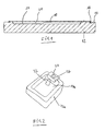
- Die Erfindung wird nachfolgend anhand einer Zeichnung näher erläutert.
- Figur 1
- zeigt einen Schnitt durch eine Leiterplatte mit Kühlkörper nach der Erfindung.
- Figur 2
- zeigt perspektivisch einen alternativen Kühlkörper mit einem schwammähnlichen Körper zwecks Volumenausgleich.
- In der Figur ist eine Leiterplatte 10 zu erkennen, die einzelne elektrische bzw. elektronische Bauelemente enthält, die jedoch nicht dargestellt sind. Bei den Bauelementen handelt es sich z. B. um Leistungsbauelemente. Daher kann die Leiterplatte z. B. die Leistungshalbleiter und ihre Steuerung für die Versorgung eines elektrischen Motors erheblich erwärmt werden. In jedem Falle erzeugen die Bauelemente in einer derartigen Leiterplatte eine große Verlustwärme. Diese wird in der Figur durch einen hier quaderförmig dargestellten Kühlkörper 12 aus gut wärmeleitendem Material abgeführt. Als Material dient z. B. Aluminium oder eine Aluminiumlegierung. Der Kühlkörper 10 kann mit Kühlrippen oder dergleichen versehen werden, um eine bessere Wärmeabfuhr an die Umgebung zu gewährleisten.
- Wie erkennbar, befindet sich im Kühlkörper 12 unterhalb der Leiterplatte 10 eine Ausnehmung 14. An der der Leiterplatte 10 zugekehrten Oberseite des Kühlkörpers 12 ist eine die Ausnehmung 14 umgebende Nut 16 eingeformt, welche ein Dichtelement 18 aufnimmt, z. B. ein O-Dichtring. Die Leiterplatte 10 wird mit geeigneten Mitteln am Kühlkörper 12 befestigt, beispielsweise durch Verschraubung. Nach der Anbringung der Leiterplatte 10 am Kühlkörper 12 ist der Raum, der durch die Ausnehmung 14 gebildet ist, gegenüber der Umgebung abgedichtet. Er ist mit einem geeigneten Kühlmedium 20 gefüllt. Das Kühlmedium ist z. B. ein Gas, eine Flüssigkeit oder ein Gel. Vorzugsweise wird ein flüssiges Kühlmittel auf Öl- oder Wasser-Glykol-Mischung-Basis verwendet.
- Das Kühlmedium 20 füllt alle Spalten zwischen Kühlkörper 12 und Leiterplatte 10 aus, wodurch ein guter Wärmeübergang von der Leiterplatte 10 zum Kühlkörper gewährleistet ist, wenn das Kühlmedium 20 selbst eine relativ gute Wärmeleiteigenschaft aufweist. Die beschriebene Flachbaugruppe wird so montiert, dass die Randebene zur Flachbaugruppeunterseite flüssigkeitsdicht ist. Dies kann z.B. auch durch vorheriges Kleben der Flachbaugruppe auf den Kühlkörper erfolgen oder durch Dichtlippen zwischen Flachbaugruppe und Kühlkörper, welche erst durch Montage des Deckels dicht gepresst wird. Bei der Montage ist das Ausgleichsvolumen bereits vorhanden und positioniert. Idealerweise wird der Kühlkörper mit montierter Flachbaugruppe aufgerichtet und vom höchsten Punkt aus befüllt mit Geliermittel und Kühlflüssigkeit. Der Gelierprozess findet während des Befiillens statt. So wird verhindert, dass unnötig Luft mit eingeschlossen wird. Sobald Flüssigkeit oben austritt, wird die Öffnung mit einem Schraub- oder Steckstopfen verschlossen.
- Weist die Unterseite der Platte 10 eine elektrische Verbindung auf, dann ist das Kühlmedium 20 elektrisch nicht leitend auszuführen.
- In
Figur 2 ist ein Kühlkörper 12a dargestellt mit einer Ausnehmung 14a ähnlich der Anordnung nachFigur 1 . In der Ausnehmung 14a ist ein Zapfen 22 angeordnet, der mit einer mittigen Bohrung 24 eines flachen schwammähnlichen Körpers 26 zusammenwirkt. Der schwammähnliche Körper 26 ist komprimierbar und dient somit als Ausgleichsvolumen bei Temperaturänderungen und damit Volumenänderungen der Kühlflüssigkeit.
Claims (9)
- Leiterplatte mit Kühlkörper, wobei der Kühlkörper mindestens eine von der Leiterplatte abgedeckte Ausnehmung aufweist für ein Kühlfluid, dadurch gekennzeichnet, dass die Leiterplatte (10) abgedichtet am Kühlkörper (12) befestigt und der so abgedichtete Raum der Ausnehmung (14) mit einem Kühlmedium (20) gefüllt ist.
- Leiterplatte mit Kühlkörper nach Anspruch 1, dadurch gekennzeichnet, dass das Kühlmedium ein Gas, eine Flüssigkeit oder ein Gel ist.
- Leiterplatte mit Kühlkörper nach Anspruch 2, dadurch gekennzeichnet, dass das Kühlmedium ein Öl oder eine Wasser-Glykol-Mischung ist.
- Leiterplatte mit Kühlkörper nach einem der Ansprüche 1 - 3, dadurch gekennzeichnet, dass das Kühlmedium (20) elektrisch nicht leitend ist.
- Leiterplatte mit Kühlkörper nach einem der Ansprüche 1 - 4, dadurch gekennzeichnet, dass im Kühlkörper ein mit der Ausnehmung verbundenes oder in der Ausnehmung angeordnetes Ausgleichsvolumen vorgesehen ist.
- Leiterplatte mit Kühlkörper nach Anspruch 6, dadurch gekennzeichnet, dass das Ausgleichsvolumen von einem komprimierbaren Körper (26) gebildet ist.
- Leiterplatte mit Kühlkörper nach Anspruch 6, dadurch gekennzeichnet, dass der komprimierbare Körper (26) eine Bohrung (24) aufweist, in die ein Stift (22) in der Ausnehmung (14a) eingreift.
- Leiterplatte mit Kühlkörper nach einem der Ansprüche 1 - 7, dadurch gekennzeichnet, dass zwischen Leiterplatte (10) und Kühlkörper (12) ein die Ausnehmung (14) umgebendes Dichtelement (18) angeordnet ist.
- Leiterplatte mit Kühlkörper nach Anspruch 8, dadurch gekennzeichnet, dass das Dichtelement (18) in einer Nut (16) des Kühlkörpers (20) angeordnet ist.
Applications Claiming Priority (1)
| Application Number | Priority Date | Filing Date | Title |
|---|---|---|---|
| DE102009010256A DE102009010256A1 (de) | 2009-02-24 | 2009-02-24 | Leiterplatte mit Kühlkörper |
Publications (2)
| Publication Number | Publication Date |
|---|---|
| EP2222150A1 true EP2222150A1 (de) | 2010-08-25 |
| EP2222150B1 EP2222150B1 (de) | 2015-10-14 |
Family
ID=42224770
Family Applications (1)
| Application Number | Title | Priority Date | Filing Date |
|---|---|---|---|
| EP10001380.4A Active EP2222150B1 (de) | 2009-02-24 | 2010-02-11 | Leiterplatte mit Kühlkörper |
Country Status (2)
| Country | Link |
|---|---|
| EP (1) | EP2222150B1 (de) |
| DE (1) | DE102009010256A1 (de) |
Cited By (1)
| Publication number | Priority date | Publication date | Assignee | Title |
|---|---|---|---|---|
| EP3525558A1 (de) * | 2018-02-12 | 2019-08-14 | IQ evolution GmbH | Leiterplatte |
Families Citing this family (5)
| Publication number | Priority date | Publication date | Assignee | Title |
|---|---|---|---|---|
| DE102014010373A1 (de) | 2014-07-12 | 2015-01-15 | Daimler Ag | Elektronisches Modul für ein Kraftfahrzeug |
| DE102014013036A1 (de) | 2014-09-02 | 2016-03-03 | Daimler Ag | Leistungsmodul für ein Kraftfahrzeug |
| EP3195711A4 (de) * | 2014-09-15 | 2018-08-29 | D'Onofrio, Nicholas, Michael | Leiterplatte mit flüssigkeitsgekühltem metallkern |
| DE102015003226A1 (de) | 2015-03-13 | 2015-12-03 | Daimler Ag | Leiterplattenanordnung für eine Wandlereinrichtung eines Kraftfahrzeugs und Bauelement mit einer Leiterplattenanordnung |
| DE102024125414A1 (de) * | 2024-09-05 | 2026-03-05 | Schaeffler Technologies AG & Co. KG | Elektronische Vorrichtung, die ein elektronisches Bauteil, eine Leiterplatte und wenigstens ein Kühlelement aufweist |
Citations (5)
| Publication number | Priority date | Publication date | Assignee | Title |
|---|---|---|---|---|
| DE69821779T2 (de) * | 1997-09-17 | 2004-12-09 | Advanced Energy's Voorhees Operations | Kühlmodul für elektronische bauelemente |
| US20050083652A1 (en) * | 2003-10-15 | 2005-04-21 | Visteon Global Technologies, Inc. | Liquid cooled semiconductor device |
| US7190581B1 (en) * | 2005-01-11 | 2007-03-13 | Midwest Research Institute | Low thermal resistance power module assembly |
| US20070215325A1 (en) * | 2004-11-24 | 2007-09-20 | General Electric Company | Double sided heat sink with microchannel cooling |
| EP1858313A1 (de) | 2006-04-27 | 2007-11-21 | Hitachi, Ltd. | Leistungsumrichter |
Family Cites Families (15)
| Publication number | Priority date | Publication date | Assignee | Title |
|---|---|---|---|---|
| US3764856A (en) * | 1972-05-17 | 1973-10-09 | Massachusetts Inst Technology | Heat transfer in electronic equipment |
| DE4010193C3 (de) * | 1990-03-30 | 1998-03-26 | Rheinmetall Ind Ag | Leiterkarte für eine Leistungs-Elektronikschaltung |
| CA2053055C (en) * | 1990-10-11 | 1997-02-25 | Tsukasa Mizuno | Liquid cooling system for lsi packages |
| DE4244721A1 (de) * | 1992-05-25 | 1994-04-21 | Mannesmann Ag | Elektrische Maschine mit fluidgekühlten Halbleiterelementen |
| DE4326207A1 (de) * | 1992-10-06 | 1994-04-07 | Hewlett Packard Co | Mechanisch schwimmendes Mehr-Chip-Substrat |
| JPH09121557A (ja) * | 1995-10-23 | 1997-05-06 | Hitachi Ltd | 回転機器の電子部品冷却構造及びその製作方法 |
| MY115676A (en) * | 1996-08-06 | 2003-08-30 | Advantest Corp | Printed circuit board with electronic devices mounted thereon |
| DE19852125C1 (de) * | 1998-11-12 | 2000-04-20 | Piller Gmbh | Vorrichtung zur unterbrechungsfreien Stromversorgung |
| DE10006215A1 (de) * | 2000-02-11 | 2001-08-16 | Abb Semiconductors Ag Baden | Kühlvorrichtung für ein Hochleistungs-Halbleitermodul |
| US20020162673A1 (en) * | 2001-05-03 | 2002-11-07 | Cook Derrick E. | Use of doped synthetic polymer materials for packaging of power electric assemblies for a liquid cooled module |
| JP3946018B2 (ja) * | 2001-09-18 | 2007-07-18 | 株式会社日立製作所 | 液冷却式回路装置 |
| DE10249436A1 (de) * | 2001-11-08 | 2003-05-22 | Tyco Electronics Amp Gmbh | Kühlkörper zur Kühlung eines Leistungsbauelements auf einer Platine |
| DE102006028675B4 (de) * | 2006-06-22 | 2008-08-21 | Siemens Ag | Kühlanordnung für auf einer Trägerplatte angeordnete elektrische Bauelemente |
| EP1887847B1 (de) * | 2006-08-10 | 2011-06-15 | Continental Automotive GmbH | Elektronikeinheit mit abgedichteter Kühlmittelpassage |
| DE102007014713B3 (de) * | 2007-03-23 | 2008-09-18 | Sew-Eurodrive Gmbh & Co. Kg | Kühlanordnung, Umrichter und elektrisches Antriebssystem |
-
2009
- 2009-02-24 DE DE102009010256A patent/DE102009010256A1/de not_active Withdrawn
-
2010
- 2010-02-11 EP EP10001380.4A patent/EP2222150B1/de active Active
Patent Citations (5)
| Publication number | Priority date | Publication date | Assignee | Title |
|---|---|---|---|---|
| DE69821779T2 (de) * | 1997-09-17 | 2004-12-09 | Advanced Energy's Voorhees Operations | Kühlmodul für elektronische bauelemente |
| US20050083652A1 (en) * | 2003-10-15 | 2005-04-21 | Visteon Global Technologies, Inc. | Liquid cooled semiconductor device |
| US20070215325A1 (en) * | 2004-11-24 | 2007-09-20 | General Electric Company | Double sided heat sink with microchannel cooling |
| US7190581B1 (en) * | 2005-01-11 | 2007-03-13 | Midwest Research Institute | Low thermal resistance power module assembly |
| EP1858313A1 (de) | 2006-04-27 | 2007-11-21 | Hitachi, Ltd. | Leistungsumrichter |
Cited By (1)
| Publication number | Priority date | Publication date | Assignee | Title |
|---|---|---|---|---|
| EP3525558A1 (de) * | 2018-02-12 | 2019-08-14 | IQ evolution GmbH | Leiterplatte |
Also Published As
| Publication number | Publication date |
|---|---|
| DE102009010256A1 (de) | 2010-08-26 |
| EP2222150B1 (de) | 2015-10-14 |
Similar Documents
| Publication | Publication Date | Title |
|---|---|---|
| EP2439774B1 (de) | Wärmeverteiler mit flexibel gelagertem Wärmerohr | |
| EP2222150B1 (de) | Leiterplatte mit Kühlkörper | |
| EP2334161A2 (de) | Steuergerät | |
| DE10250604A1 (de) | Integriertes Schaltungssystem mit Latentwärmespeichermodul | |
| EP1858079A2 (de) | Anordnung zur Kühlung von SMD-Leistungsbauelementen auf einer Leiterplatte | |
| DE19506664A1 (de) | Elektrisches Gerät | |
| DE102013102829B4 (de) | Leistungshalbleitermodul und Anordnung hiermit | |
| DE19855389A1 (de) | Elektronische Vorrichtung | |
| DE3735985C2 (de) | ||
| DE102005049872B4 (de) | IC-Bauelement mit Kühlanordnung | |
| WO2018145931A1 (de) | Leiterplatte mit einer kühlfunktion | |
| DE102005036299B4 (de) | Kühlanordnung | |
| DE10214363A1 (de) | Kühlanordnung und Elektrogerät mit einer Kühlanordnung | |
| DE202013002411U1 (de) | Wärmeverteiler mit Flachrohrkühlelement | |
| DE102006008807B4 (de) | Anordnung mit einem Leistungshalbleitermodul und einem Kühlbauteil | |
| DE4435510C1 (de) | Frequenzumrichtergespeistes Pumpenaggregat | |
| EP2439775A2 (de) | Wärmeverteiler mit mechanisch gesichertem Wärmekopplungselement | |
| EP1363485B1 (de) | Kühlelement | |
| AT411126B (de) | Halbleitermodul | |
| DE102014216170B3 (de) | Elektronikmodul | |
| EP2006910B1 (de) | Leistungselektronikmodul | |
| DE3219571A1 (de) | Gehaeuse fuer elektronische schaltungen | |
| DE112019002408T5 (de) | Schaltungsanordnung und elektrischer anschlusskasten | |
| EP3629687A1 (de) | Verfahren für eine montage eines elektrischen geräts | |
| DE102005053396B4 (de) | Schaltungseinrichtung, insbesondere Frequenzumrichter |
Legal Events
| Date | Code | Title | Description |
|---|---|---|---|
| PUAI | Public reference made under article 153(3) epc to a published international application that has entered the european phase |
Free format text: ORIGINAL CODE: 0009012 |
|
| AK | Designated contracting states |
Kind code of ref document: A1 Designated state(s): AT BE BG CH CY CZ DE DK EE ES FI FR GB GR HR HU IE IS IT LI LT LU LV MC MK MT NL NO PL PT RO SE SI SK SM TR |
|
| AX | Request for extension of the european patent |
Extension state: AL BA RS |
|
| 17P | Request for examination filed |
Effective date: 20101208 |
|
| 17Q | First examination report despatched |
Effective date: 20121102 |
|
| GRAP | Despatch of communication of intention to grant a patent |
Free format text: ORIGINAL CODE: EPIDOSNIGR1 |
|
| RIC1 | Information provided on ipc code assigned before grant |
Ipc: H01L 23/473 20060101ALI20150424BHEP Ipc: H01L 23/467 20060101ALI20150424BHEP Ipc: H05K 7/20 20060101AFI20150424BHEP |
|
| INTG | Intention to grant announced |
Effective date: 20150521 |
|
| GRAS | Grant fee paid |
Free format text: ORIGINAL CODE: EPIDOSNIGR3 |
|
| GRAA | (expected) grant |
Free format text: ORIGINAL CODE: 0009210 |
|
| AK | Designated contracting states |
Kind code of ref document: B1 Designated state(s): AT BE BG CH CY CZ DE DK EE ES FI FR GB GR HR HU IE IS IT LI LT LU LV MC MK MT NL NO PL PT RO SE SI SK SM TR |
|
| REG | Reference to a national code |
Ref country code: GB Ref legal event code: FG4D Free format text: NOT ENGLISH |
|
| REG | Reference to a national code |
Ref country code: AT Ref legal event code: REF Ref document number: 755916 Country of ref document: AT Kind code of ref document: T Effective date: 20151015 Ref country code: CH Ref legal event code: EP |
|
| REG | Reference to a national code |
Ref country code: IE Ref legal event code: FG4D Free format text: LANGUAGE OF EP DOCUMENT: GERMAN |
|
| REG | Reference to a national code |
Ref country code: DE Ref legal event code: R096 Ref document number: 502010010441 Country of ref document: DE |
|
| REG | Reference to a national code |
Ref country code: NL Ref legal event code: MP Effective date: 20151014 |
|
| REG | Reference to a national code |
Ref country code: LT Ref legal event code: MG4D |
|
| REG | Reference to a national code |
Ref country code: FR Ref legal event code: PLFP Year of fee payment: 7 |
|
| PG25 | Lapsed in a contracting state [announced via postgrant information from national office to epo] |
Ref country code: NL Free format text: LAPSE BECAUSE OF FAILURE TO SUBMIT A TRANSLATION OF THE DESCRIPTION OR TO PAY THE FEE WITHIN THE PRESCRIBED TIME-LIMIT Effective date: 20151014 Ref country code: LT Free format text: LAPSE BECAUSE OF FAILURE TO SUBMIT A TRANSLATION OF THE DESCRIPTION OR TO PAY THE FEE WITHIN THE PRESCRIBED TIME-LIMIT Effective date: 20151014 Ref country code: ES Free format text: LAPSE BECAUSE OF FAILURE TO SUBMIT A TRANSLATION OF THE DESCRIPTION OR TO PAY THE FEE WITHIN THE PRESCRIBED TIME-LIMIT Effective date: 20151014 Ref country code: IS Free format text: LAPSE BECAUSE OF FAILURE TO SUBMIT A TRANSLATION OF THE DESCRIPTION OR TO PAY THE FEE WITHIN THE PRESCRIBED TIME-LIMIT Effective date: 20160214 Ref country code: HR Free format text: LAPSE BECAUSE OF FAILURE TO SUBMIT A TRANSLATION OF THE DESCRIPTION OR TO PAY THE FEE WITHIN THE PRESCRIBED TIME-LIMIT Effective date: 20151014 Ref country code: IT Free format text: LAPSE BECAUSE OF FAILURE TO SUBMIT A TRANSLATION OF THE DESCRIPTION OR TO PAY THE FEE WITHIN THE PRESCRIBED TIME-LIMIT Effective date: 20151014 Ref country code: NO Free format text: LAPSE BECAUSE OF FAILURE TO SUBMIT A TRANSLATION OF THE DESCRIPTION OR TO PAY THE FEE WITHIN THE PRESCRIBED TIME-LIMIT Effective date: 20160114 |
|
| PG25 | Lapsed in a contracting state [announced via postgrant information from national office to epo] |
Ref country code: FI Free format text: LAPSE BECAUSE OF FAILURE TO SUBMIT A TRANSLATION OF THE DESCRIPTION OR TO PAY THE FEE WITHIN THE PRESCRIBED TIME-LIMIT Effective date: 20151014 Ref country code: PT Free format text: LAPSE BECAUSE OF FAILURE TO SUBMIT A TRANSLATION OF THE DESCRIPTION OR TO PAY THE FEE WITHIN THE PRESCRIBED TIME-LIMIT Effective date: 20160215 Ref country code: PL Free format text: LAPSE BECAUSE OF FAILURE TO SUBMIT A TRANSLATION OF THE DESCRIPTION OR TO PAY THE FEE WITHIN THE PRESCRIBED TIME-LIMIT Effective date: 20151014 Ref country code: BE Free format text: LAPSE BECAUSE OF NON-PAYMENT OF DUE FEES Effective date: 20160229 Ref country code: LV Free format text: LAPSE BECAUSE OF FAILURE TO SUBMIT A TRANSLATION OF THE DESCRIPTION OR TO PAY THE FEE WITHIN THE PRESCRIBED TIME-LIMIT Effective date: 20151014 Ref country code: GR Free format text: LAPSE BECAUSE OF FAILURE TO SUBMIT A TRANSLATION OF THE DESCRIPTION OR TO PAY THE FEE WITHIN THE PRESCRIBED TIME-LIMIT Effective date: 20160115 Ref country code: SE Free format text: LAPSE BECAUSE OF FAILURE TO SUBMIT A TRANSLATION OF THE DESCRIPTION OR TO PAY THE FEE WITHIN THE PRESCRIBED TIME-LIMIT Effective date: 20151014 |
|
| REG | Reference to a national code |
Ref country code: DE Ref legal event code: R097 Ref document number: 502010010441 Country of ref document: DE |
|
| PG25 | Lapsed in a contracting state [announced via postgrant information from national office to epo] |
Ref country code: CZ Free format text: LAPSE BECAUSE OF FAILURE TO SUBMIT A TRANSLATION OF THE DESCRIPTION OR TO PAY THE FEE WITHIN THE PRESCRIBED TIME-LIMIT Effective date: 20151014 |
|
| PLBE | No opposition filed within time limit |
Free format text: ORIGINAL CODE: 0009261 |
|
| STAA | Information on the status of an ep patent application or granted ep patent |
Free format text: STATUS: NO OPPOSITION FILED WITHIN TIME LIMIT |
|
| PG25 | Lapsed in a contracting state [announced via postgrant information from national office to epo] |
Ref country code: EE Free format text: LAPSE BECAUSE OF FAILURE TO SUBMIT A TRANSLATION OF THE DESCRIPTION OR TO PAY THE FEE WITHIN THE PRESCRIBED TIME-LIMIT Effective date: 20151014 Ref country code: DK Free format text: LAPSE BECAUSE OF FAILURE TO SUBMIT A TRANSLATION OF THE DESCRIPTION OR TO PAY THE FEE WITHIN THE PRESCRIBED TIME-LIMIT Effective date: 20151014 Ref country code: SK Free format text: LAPSE BECAUSE OF FAILURE TO SUBMIT A TRANSLATION OF THE DESCRIPTION OR TO PAY THE FEE WITHIN THE PRESCRIBED TIME-LIMIT Effective date: 20151014 Ref country code: RO Free format text: LAPSE BECAUSE OF FAILURE TO SUBMIT A TRANSLATION OF THE DESCRIPTION OR TO PAY THE FEE WITHIN THE PRESCRIBED TIME-LIMIT Effective date: 20151014 Ref country code: SM Free format text: LAPSE BECAUSE OF FAILURE TO SUBMIT A TRANSLATION OF THE DESCRIPTION OR TO PAY THE FEE WITHIN THE PRESCRIBED TIME-LIMIT Effective date: 20151014 |
|
| 26N | No opposition filed |
Effective date: 20160715 |
|
| PG25 | Lapsed in a contracting state [announced via postgrant information from national office to epo] |
Ref country code: MC Free format text: LAPSE BECAUSE OF FAILURE TO SUBMIT A TRANSLATION OF THE DESCRIPTION OR TO PAY THE FEE WITHIN THE PRESCRIBED TIME-LIMIT Effective date: 20151014 Ref country code: LU Free format text: LAPSE BECAUSE OF FAILURE TO SUBMIT A TRANSLATION OF THE DESCRIPTION OR TO PAY THE FEE WITHIN THE PRESCRIBED TIME-LIMIT Effective date: 20160211 |
|
| REG | Reference to a national code |
Ref country code: CH Ref legal event code: PL |
|
| PG25 | Lapsed in a contracting state [announced via postgrant information from national office to epo] |
Ref country code: LI Free format text: LAPSE BECAUSE OF NON-PAYMENT OF DUE FEES Effective date: 20160229 Ref country code: CH Free format text: LAPSE BECAUSE OF NON-PAYMENT OF DUE FEES Effective date: 20160229 |
|
| PG25 | Lapsed in a contracting state [announced via postgrant information from national office to epo] |
Ref country code: SI Free format text: LAPSE BECAUSE OF FAILURE TO SUBMIT A TRANSLATION OF THE DESCRIPTION OR TO PAY THE FEE WITHIN THE PRESCRIBED TIME-LIMIT Effective date: 20151014 |
|
| REG | Reference to a national code |
Ref country code: IE Ref legal event code: MM4A |
|
| PG25 | Lapsed in a contracting state [announced via postgrant information from national office to epo] |
Ref country code: IE Free format text: LAPSE BECAUSE OF NON-PAYMENT OF DUE FEES Effective date: 20160211 |
|
| REG | Reference to a national code |
Ref country code: FR Ref legal event code: PLFP Year of fee payment: 8 |
|
| REG | Reference to a national code |
Ref country code: AT Ref legal event code: MM01 Ref document number: 755916 Country of ref document: AT Kind code of ref document: T Effective date: 20160211 |
|
| PG25 | Lapsed in a contracting state [announced via postgrant information from national office to epo] |
Ref country code: AT Free format text: LAPSE BECAUSE OF NON-PAYMENT OF DUE FEES Effective date: 20160211 |
|
| PG25 | Lapsed in a contracting state [announced via postgrant information from national office to epo] |
Ref country code: MT Free format text: LAPSE BECAUSE OF FAILURE TO SUBMIT A TRANSLATION OF THE DESCRIPTION OR TO PAY THE FEE WITHIN THE PRESCRIBED TIME-LIMIT Effective date: 20151014 |
|
| REG | Reference to a national code |
Ref country code: FR Ref legal event code: PLFP Year of fee payment: 9 |
|
| PG25 | Lapsed in a contracting state [announced via postgrant information from national office to epo] |
Ref country code: HU Free format text: LAPSE BECAUSE OF FAILURE TO SUBMIT A TRANSLATION OF THE DESCRIPTION OR TO PAY THE FEE WITHIN THE PRESCRIBED TIME-LIMIT; INVALID AB INITIO Effective date: 20100211 Ref country code: CY Free format text: LAPSE BECAUSE OF FAILURE TO SUBMIT A TRANSLATION OF THE DESCRIPTION OR TO PAY THE FEE WITHIN THE PRESCRIBED TIME-LIMIT Effective date: 20151014 |
|
| PG25 | Lapsed in a contracting state [announced via postgrant information from national office to epo] |
Ref country code: MK Free format text: LAPSE BECAUSE OF FAILURE TO SUBMIT A TRANSLATION OF THE DESCRIPTION OR TO PAY THE FEE WITHIN THE PRESCRIBED TIME-LIMIT Effective date: 20151014 Ref country code: TR Free format text: LAPSE BECAUSE OF FAILURE TO SUBMIT A TRANSLATION OF THE DESCRIPTION OR TO PAY THE FEE WITHIN THE PRESCRIBED TIME-LIMIT Effective date: 20151014 |
|
| PG25 | Lapsed in a contracting state [announced via postgrant information from national office to epo] |
Ref country code: BG Free format text: LAPSE BECAUSE OF FAILURE TO SUBMIT A TRANSLATION OF THE DESCRIPTION OR TO PAY THE FEE WITHIN THE PRESCRIBED TIME-LIMIT Effective date: 20151014 |
|
| PGFP | Annual fee paid to national office [announced via postgrant information from national office to epo] |
Ref country code: GB Payment date: 20260219 Year of fee payment: 17 |
|
| PGFP | Annual fee paid to national office [announced via postgrant information from national office to epo] |
Ref country code: DE Payment date: 20260217 Year of fee payment: 17 |
|
| PGFP | Annual fee paid to national office [announced via postgrant information from national office to epo] |
Ref country code: FR Payment date: 20260223 Year of fee payment: 17 |