EP2222108A1 - Terminal device and feedback method - Google Patents
Terminal device and feedback method Download PDFInfo
- Publication number
- EP2222108A1 EP2222108A1 EP08856015A EP08856015A EP2222108A1 EP 2222108 A1 EP2222108 A1 EP 2222108A1 EP 08856015 A EP08856015 A EP 08856015A EP 08856015 A EP08856015 A EP 08856015A EP 2222108 A1 EP2222108 A1 EP 2222108A1
- Authority
- EP
- European Patent Office
- Prior art keywords
- threshold value
- reception quality
- pmi
- frequency bands
- base station
- Prior art date
- Legal status (The legal status is an assumption and is not a legal conclusion. Google has not performed a legal analysis and makes no representation as to the accuracy of the status listed.)
- Withdrawn
Links
- 238000000034 method Methods 0.000 title claims abstract description 41
- 238000004891 communication Methods 0.000 claims abstract description 83
- 238000005259 measurement Methods 0.000 claims abstract description 28
- 239000011159 matrix material Substances 0.000 claims description 52
- 238000012545 processing Methods 0.000 abstract description 31
- 230000005540 biological transmission Effects 0.000 description 24
- 230000007423 decrease Effects 0.000 description 8
- 238000005516 engineering process Methods 0.000 description 6
- 238000010586 diagram Methods 0.000 description 4
- 230000000694 effects Effects 0.000 description 4
- 230000014509 gene expression Effects 0.000 description 3
- 229920006934 PMI Polymers 0.000 description 2
- 230000003247 decreasing effect Effects 0.000 description 2
- 239000000284 extract Substances 0.000 description 2
- 230000008054 signal transmission Effects 0.000 description 2
- 230000007774 longterm Effects 0.000 description 1
- 238000012986 modification Methods 0.000 description 1
- 230000004048 modification Effects 0.000 description 1
Images



Classifications
-
- H—ELECTRICITY
- H04—ELECTRIC COMMUNICATION TECHNIQUE
- H04W—WIRELESS COMMUNICATION NETWORKS
- H04W24/00—Supervisory, monitoring or testing arrangements
- H04W24/10—Scheduling measurement reports ; Arrangements for measurement reports
Definitions
- the present invention relates to a terminal device and a feedback method, and more particularly to a terminal device and feedback method for carrying out wireless communication using a precoding technology.
- terminals In order to control wireless sources in frequency-selective channels in a wireless communication system that uses a multicarrier transmission mode such as OFDM (Orthogonal Frequency Division Multiplexing), terminals measure the reception quality of channels for each frequency band and report to the wireless base station a CQI (Channel Quality Indicator) that indicates this reception quality.
- a CQI Channel Quality Indicator
- Patent Document 1 JP-A-2007-166118
- a precoding technique is applied before signal transmission to reduce the occurrence of data errors by compensating for distortion (characteristic) of a channel according to the channel condition.
- the wireless base station multiplies the signal with a precoding matrix that indicates the inverse characteristics of the channel characteristics.
- the terminal carries out decoding after multiplying the signal that was received from the wireless base station with the inverse matrix of the precoding matrix. In this way, distortion of the channel can be compensated for and the occurrence of data errors can be reduced.
- the precoding matrix that is multiplied with the signal by the wireless base station is specified in the terminal. More specifically, the terminal calculates a PMI (Precoding Matrix Index) for specifying an appropriate precoding matrix based on the channel state of the subcarrier contained in the frequency band and a codebook that is prepared in advance.
- the codebook is information in which precoding matrices are placed in correspondence with each PMI.
- the terminal separately calculates PMI for each frequency band, whereby distortion of the channels can be compensated for each of channels having mutually differing characteristics and reception quality can be improved.
- the load is increased in this case because the terminal calculates PMI separately for each frequency band.
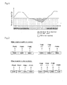
- a method is proposed whereby a terminal calculates PMI only for frequency bands for which a CQI is reported to the wireless base station, as shown in FIG. 1 .
- a Best-M individual scheme is used as the method of reporting CQI.
- a terminal successively reports a predetermined number of CQIs from a frequency band having good reception quality.
- the number of the PMI to be calculated can thus be reduced and the load of the terminal can thus be reduced.
- a method was further proposed in 3GPP TSG RAN WGI Meeting #49 bis R1-073082 in which a terminal alters the width of a frequency band for which PMI is calculated according to the reception quality, as shown in FIG. 2 .
- the terminal broadens frequency bands for which PMI is calculated as the reception quality increases.
- PMI is calculated individually for each frequency band even for frequency bands having good reception quality.
- reception quality is good
- efficiency of compensating for the channel characteristic is low even when individual precoding matrices are multiplied by the signal for each frequency band because the channel distortion is low from the start.
- the overhead expended in the PMI calculation process becomes high.
- PMI is calculated individually for each of the frequency bands even for frequency bands having inferior reception quality.
- reception quality is inferior, the possibility of assigning that frequency band during signal transmission is low.
- the possibility of using a precoding matrix that is specified by that PMI is low even if the PMI is calculated.
- the overhead expended in the PMI calculation process becomes high.
- the terminal device includes: a reception means for receiving a signal from a wireless base station; a measurement means for measuring, for each of frequency bands that have been determined in advance, reception quality of a signal received by the reception means; a judgment means for judging, for each of the frequency bands, whether the reception quality measured by the measurement means is greater than a first threshold value; a calculation means for individually calculating, for each frequency band in which the reception quality is equal to or less than the first threshold value, an individual PMI for specifying a precoding matrix for compensating for channel distortion of that frequency band, and further, calculating, for frequency bands in which the reception quality is greater than the first threshold value, a common PMI for specifying a precoding matrix for compensating for channel distortion common to these frequency bands; and a report means for reporting to the wireless base station the correspondence between the frequency bands and the individual PMI and common PMI that were calculated in the calculation means.
- the feedback method is a feedback method carried out by a terminal device that can connect with a wireless base station and includes: a reception step of receiving a signal from the wireless base station; a measurement step of measuring, for each of the frequency bands that have been determined in advance, the reception quality of the received signal; a judgment step of judging, for each of the frequency bands, whether the measured reception quality is greater than a first threshold value or not; an individual calculation step of individually calculating for each of the frequency bands in which the reception quality is no greater than the first threshold value individual PMI for specifying a precoding matrix for compensating for channel distortion of that frequency band; a common calculation step of calculating, for frequency bands in which the reception quality is greater than the first threshold value, a common PMI for specifying a precoding matrix for compensating for common channel distortion for the frequency bands; and a reporting step of reporting to the wireless base station the correspondence between the individual PMI and common PMI that were calculated and the frequency bands.
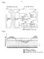
- FIG. 3 is a block diagram showing the wireless communication system of the first explanatory embodiment of the present invention.
- the wireless communication system includes wireless base station 10 and portable terminal 11. Wireless base station 10 and portable terminal 11 can connect with each other wirelessly.
- Wireless base station 10 includes communication processing unit 12.
- Communication processing unit 12 carries out processing relating to communication.
- communication processing unit 12 receives PMI report information for reporting PMI from portable terminal 11.
- the PMI report information is assumed to include band information indicating the frequency band and a PMI for specifying a precoding matrix for compensating for channel distortion of the frequency band.
- communication processing unit 12 sets a channel for each predetermined frequency band and uses this channel to transmit signals to portable terminal 11.
- communication processing unit 12 multiplies the signal with the precoding matrix specified in the PMI included in the PMI report information and then transmits the multiplied signal.
- Communication processing unit 12 is also assumed to use MIMO (Multiple Input Multiple Output) to transmit signals.
- MIMO is a technology for using a plurality of antennas to transmit and receive signals.
- Portable terminal 11 includes communication processing unit 13, reception quality measurement unit 14, reception quality judgment unit 15, and PMI calculation & report unit 16.
- Communication processing unit 13 is one example of the reception means and carries out processing relating to communication.
- communication processing unit 13 receives signals from wireless base station 10.
- Reception quality measurement unit 14 is one example of the measurement means. Reception quality measurement unit 14 measures, for each frequency band, the reception quality of the signal that is received by communication processing unit 13. In the present explanatory embodiment, the reception quality is the CQI. However, the reception quality can be altered as appropriate and is not limited to CQI. For example, the reception quality may be the SNR (Signal to Noise Ratio) or CNR (Carrier to Noise Ratio).
- Reception quality judgment unit 15 judges, for each frequency band, whether the reception quality measured in reception quality measurement unit 14 is greater than a first threshold value or not. Reception quality judgment unit 15 further determines, for each frequency band, whether the reception quality is greater than a second threshold value.
- the second threshold value is lower than the first threshold value.
- the first threshold value and the second threshold value are assumed to be fixed values.
- PMI calculation & report unit 16 calculates the PMI, and further, reports the correspondence of the PMI and frequency bands to wireless base station 10. More specifically, PMI calculation & report unit 16 includes calculation unit 16a and report unit 16b, and each unit carries out the processes described below.
- Calculation unit 16a calculates a PMI that is common to frequency bands for which the reception quality is determined in reception quality judgment unit 15 to be greater than the first threshold value and frequency bands for which the reception quality is determined by reception quality judgment unit 15 to be equal to or less than the second threshold value.
- This PMI is hereinbelow referred to as the common PMI.
- Calculation unit 16a further individually calculates a PMI for each of frequency bands for which reception quality is determined by reception quality judgment unit 15 to be equal to or less than the first threshold value, and moreover, greater than the second threshold value. These PMI are hereinbelow referred to as individual PMI.
- reception quality measurement unit 14 estimates the subcarrier channel states contained in all frequency bands, and calculation unit 16a calculates the common PMI based on the estimated channel states.
- calculation unit 16a When calculating the individual PMI, calculation unit 16a extracts the channel states of subcarriers contained in the frequency bands that correspond to the individual PMI from the channel states of subcarriers contained in all frequency bands and calculates individual PMI based on the extracted channel states.
- calculation unit 16a first uses Equation 1 to calculate a metric MSE(F i ) for each precoding matrix F i contained in a codebook that is held in advance.
- the codebook is information in which a precoding matrix is placed in correspondence with each PMI.
- MSE F i ⁇ M ⁇ I + ⁇ MN ⁇ F i * ⁇ H * ⁇ H ⁇ F i - 1
- H is a channel estimation matrix that indicates the channel state
- M is the number of transmission antennas of wireless base station 10
- ⁇ is the transmission power of wireless base station 10
- N is the noise power.
- ⁇ /N is the SN ratio. If it is assumed that I is the identity matrix of M ⁇ M and A is a matrix, then:
- a - 1 is the inverse matrix of A
- a * represents the conjugate transpose matrix of A.
- A represents a matrix.
- the channel estimation matrix is a matrix having as components a channel estimate value for each subcarrier that corresponds to each of M transmission antennas.
- Each channel estimate value is a value indicating the channel state of a particular subcarrier that was transmitted by a particular transmission antenna.
- calculation unit 16a uses, as the channel estimation matrix, a matrix having as components the channel estimate values of each subcarrier contained in all frequency bands for each of the transmission antennas.
- the channel estimation matrix is a matrix of: [the number of subcarriers contained in all frequency bands] x M.
- calculation unit 16a uses as the channel estimation matrix, a matrix having as components the channel estimate values of each subcarrier contained in the frequency band that corresponds to the individual PMI for each of the transmission antennas.
- the channel estimation matrix is a matrix of: [the number of subcarriers contained in the frequency band that corresponds to the individual PMI] x M.
- the channel estimate values, the number N of transmission antennas, transmission power ⁇ , and SN ratio are measured in reception quality measurement unit 14.
- Calculation unit 16a uses Equation 4 to calculate the PMI from within metric MSE(F i ).
- F arg min F i ⁇ F m MSE F i
- m(A) indicates the trace or the matrix expression of A.
- F indicates the set of precoding matrices contained in the codebook that is held in advance.
- calculation unit 16a finds, as the PMI, the precoding matrix F i that gives the minimum value among the traces or matrix expressions of metric MSE(F i ).
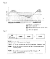
- FIG. 4 is an explanatory view showing an example of the frequency band for which the common PMI and individual PMI are reported.
- an individual PMI is individually calculated for each of the frequency bands for which the CQI is equal to or less than the first threshold value, and moreover, greater than the second threshold value.
- the common PMI takes the place of the PMI of the frequency bands and an individual PMI is not calculated.
- a common PMI is calculated that is common to these frequency bands.
- report unit 16b reports to wireless base station 10 the correspondence between the frequency bands and the individual PMI and common PMI that were calculated by calculation unit 16a.
- report unit 16b reports to wireless base station 10 PMI report information that contains the PMI that was computed by calculation unit 16a and band information that indicates the frequency bands that correspond to the PMI.
- FIG. 5 is a flow chart for explaining an example of the operation of portable terminal 11.
- Step S1 communication processing unit 13 receives a signal from communication processing unit 12 of wireless base station 10 and transmits this signal to reception quality measurement unit 14.
- Reception quality measurement unit 14 measures, for each frequency band, the reception quality of the signal that was received by communication processing unit 13. Reception quality measurement unit 14 generates quality information that places the reception quality in correspondence with each frequency band.
- reception quality measurement unit 14 finds computation information that is used in the computation of the PMI.
- the computation information includes a channel estimation matrix, the transmission antenna number, the transmission power, and the SN ratio.
- the channel estimation matrix is a matrix that has as components channel estimate values of each of the subcarriers that are included in all frequency bands corresponding to each of the transmission antennas.
- Reception quality measurement unit 14 further finds each channel estimate value based on pilot symbols contained in the signal from wireless base station 10 and pilot symbols that are unique to wireless base station 10.
- Reception quality measurement unit 14 transmits the quality information and computation information to reception quality judgment unit 15. Upon receiving the quality information and computation information, reception quality judgment unit 15 executes Step S2.
- Step S2 reception quality judgment unit 15 transmits the computation information to calculation unit 16a.
- Calculation unit 16a upon receiving the computation information, calculates the common PMI based on the computation information and the codebook.
- calculation unit 16a first substitutes into Equation 1 the channel estimation matrix, transmission antenna number, transmission power, and SN ratio in the computation information for each precoding matrix F i contained in the codebook and calculates metric MSE(F i ).
- Calculation unit 16a next uses Equation 4 to find, as the common PMI, precoding matrix F i that gives the minimum value among the traces or metric MSE(F i ).
- calculation unit 16a Upon calculating the common PMI, calculation unit 16a transmits a start request indicating the start of determination to reception quality judgment unit 15. Upon receiving the reception quality, reception quality judgment unit 15 executes Step S3.
- reception quality judgment unit 15 selects band information in the reception information, and determines whether the reception quality that was placed in correspondence with the band information is greater than the first threshold value.
- Reception quality judgment unit 15 here selects one item of band information from among the band information that has still not been selected.
- Reception quality judgment unit 15 executes Step S4 when the reception quality is greater than the first threshold value and executes Step S5 when the reception quality is equal to or less than the first threshold value.
- Step S4 reception quality judgment unit 15 transmits the band information that was selected and superior information indicating that reception quality is superior to calculation unit 16a.
- Calculation unit 16a having received the band information and superior information, generates PMI report information that includes the common PMI that was computed in Step S2 and the band information, and saves the PMI report information.
- Calculation unit 16a after completing Step S4, executes Step S8.
- reception quality judgment unit 15 determines whether the reception quality that was placed in correspondence with the band information that was selected in Step S3 is greater than the second threshold value. Reception quality judgment unit 15 executes Step S6 if the reception quality is greater than the second threshold value and executes Step S7 if the reception quality is equal to or less than the second threshold value.
- reception quality judgment unit 15 transmits to calculation unit 16a the selected band information and intermediate information indicating that the reception quality is intermediate.
- calculation unit 16a calculates individual PMI based on the computation information received in Step S2 and on the codebook.
- calculation unit 16a extracts from the channel estimation matrices in the computation information a partial matrix indicating the channel state of subcarriers contained in the frequency band that is indicated by the band information.
- Calculation unit 16a next substitutes into Equation 1 the extracted partial matrix and the transmission antenna number, transmission power, and SN ratio in the computation information for each precoding matrix F i contained in the codebook to calculate metric MSE(F i ).
- Calculation unit 16a here substitutes into Equation 1 the partial matrix as the channel estimation matrix.
- Calculation unit 16a then uses Equation 4 to find, as the PMI, precoding matrix Fi that gives the minimum value among the traces or matrix expressions of metric MSE(F i ).
- calculation unit 16a Upon computing the individual PMI, calculation unit 16a generates PMI report information that includes the individual PMI and band information and holds this PMI report information. After completing Step S6, calculation unit 16a executes Step S8.
- Step S7 reception quality judgment unit 15 transmits to calculation unit 16a the band information that was selected and inferior information indicating that the reception quality is inferior.
- Calculation unit 16a having received the band information and inferior information, generates PMI report information that includes the common PMI that was calculated in Step S2 and the band information, and holds the PMI report information.
- Step S8 calculation unit 16a executes Step S8.
- Step S8 calculation unit 16a transmits to reception quality judgment unit 15 computation completion information indicating that the PMI has been computed.
- reception quality judgment unit 15 determines whether or not all band information has been selected. Reception quality judgment unit 15 executes Step S9 if all band information has been selected and executes Step S3 if unselected band information remains.
- Step S9 reception quality judgment unit 15 transmits to calculation unit 16a report instructions indicating that PMI report information should be reported.
- calculation unit 16a Upon receiving the report instructions, calculation unit 16a transmits the PMI report information to report unit 16b.
- Report unit 16b having received the PMI report information, transmits the PMI report information to wireless base station 10 to complete the process.
- Steps S1 to S9 may be repeated while wireless base station 10 and portable terminal 11 are connected.
- reception quality measurement unit 14 measures the reception quality of a signal received by communication processing unit 13 for each block frequency band.
- Reception quality judgment unit 15 determines whether the reception quality is greater than a first threshold value for each block frequency band.
- Calculation unit 16a individually computes an individual PMI for each frequency band for which the reception quality is equal to or less than the first threshold value.
- Calculation unit 16a further computes, for frequency bands for which the reception quality is greater than the first threshold value, a common PMI that is shared among these frequency bands.
- Report unit 16b reports to the wireless base station the correspondence between the frequency bands and the individual PMI and common PMI that were computed.
- reception quality judgment unit 15 determines for each frequency band whether the reception quality is greater than a second threshold value that is lower than the first threshold value.
- Calculation unit 16a individually computes an individual PMI for each frequency band for which the reception quality is greater than the second threshold value.
- an individual PMI is individually computed for each frequency band for which the reception quality is greater than the second threshold value.
- Eliminating the need to individually compute a PMI for each frequency band for which the reception quality is inferior enables a reduction of the overhead expended in the PMI computation process.
- calculation unit 16a computes, for frequency bands in which the reception quality is greater than the first threshold value and frequency bands in which the reception quality is equal to or less than the second threshold value, a common PMI that is common to these frequency bands.
- a PMI can be computed for frequency bands in which the reception quality is inferior. Accordingly, a PMI can be computed for frequency bands in which the reception quality is inferior while reducing the overhead expended in the PMI computation process.
- calculation unit 16a computes PMI only for frequency bands for which reception quality judgment unit 15 has determined that reception quality is greater than the second threshold value.
- calculation unit 16a individually computes an individual PMI for each frequency band for which the reception quality is equal to or less than the first threshold value and for each frequency band for which the reception quality is greater than the second threshold value. For frequency bands for which the reception quality is greater than the first threshold value, calculation unit 16a computes a common PMI that is common to these frequency bands. Calculation unit 16a then does not compute PMI for frequency bands for which the reception quality is equal to or less than the second threshold value.
- FIG. 6 is an explanatory view showing an example of the frequency band for reporting the common PMI and individual PMI.
- an individual PMI is individually computed for each frequency band for which the reception quality is equal to or less than the first threshold value, and moreover, for which the reception quality is greater than the second threshold value.
- a common PMI that is common to these frequency bands is computed.
- a PMI is not computed in frequency bands for which the reception quality is equal to or less than the second threshold value.
- the need to individually compute PMI is eliminated for each frequency band in which the reception quality is inferior, and the overhead expended for the PMI computation process can therefore be reduced.
- report unit 16b reports the correspondence between the PMI and frequency bands by the following format.
- Report unit 16b transmits quality information, first threshold value, and second threshold value to wireless base station 10. Report unit 16b further transmits information in which the PMI are arranged in a predetermined order as PMI report information.
- FIG. 7 is an explanatory view showing an example of the PMI report information.
- the common PMI is set as the first PMI and, in the second and succeeding PMI, individual PMI are arranged in order from the frequency band having the lowest frequency.
- Communication processing unit 12 of wireless base station 10 upon receiving the quality information, first threshold value, second threshold value, and PMI report information, specifies the PMI of the frequency band for each frequency band based on the quality information, first threshold value, second threshold value, and PMI report information.
- communication processing unit 12 first determines for each frequency band whether the reception quality is greater than the first threshold value or not based on the quality information received from portable terminal 11.
- Communication processing unit 12 further determines for each frequency band whether the reception quality is greater than the second threshold value.
- Communication processing unit 12 specifies the first PMI of the PMI report information as the PMI of frequency bands for which the reception quality is greater than the first threshold value.
- Communication processing unit 12 further successively specifies, as the PMI for frequency bands for which the reception quality is equal to or less than the first threshold value and moreover, greater than the second threshold value, PMI in order of lower frequency from the second PMI of the PMI report information.
- the common PMI in all frequency bands need only be reported once, and the amount of PMI transmissions can therefore be reduced. As a result, interference can be reduced in all uplink lines.
- FIG. 8 is a flow chart for explaining an example of the operation of portable terminal 11 of the present explanatory embodiment.
- the same reference numbers are given to processes that are identical to FIG. 5 and redundant explanation of these processes is omitted.
- reception quality judgment unit 15 executes Step S8 when the reception quality is greater than the first threshold value and executes Step S5 when the reception quality is equal to or less than the first threshold value.
- reception quality judgment unit 15 executes Step S6' if the reception quality is greater than the second threshold value and executes Step S8 if the reception quality is equal to or less than the second threshold value.
- Step S6' reception quality judgment unit 15 transmits to calculation unit 16a the selected band information and intermediate information indicating that the reception quality is intermediate.
- Calculation unit 16a upon receiving the band information and intermediate information, computes the individual PMI based on the computation information received in Step S2 and the codebook. Calculation unit 16a holds this individual PMI and the band information in mutual correspondence. Upon completion of Step S6', calculation unit 16a executes Step S8.
- reception quality judgment unit 15 executes Step S9'.
- Step S9' reception quality judgment unit 15 transmits report instructions to calculation unit 16a.
- calculation unit 16a Upon receiving the report instructions, calculation unit 16a generates PMI report information based on the common PMI and PMI hold information. For example, calculation unit 16a first generates PMI report information that takes the common PMI computed in Step S2 as the first PMI. Calculation unit 16a next arranges the held individual PMI in order from the second item of PMI report information starting from the individual PMI that is placed in correspondence with band information that indicates the frequency band having the lowest frequency.
- calculation unit 16a When PMI report information has been generated, calculation unit 16a transmits the PMI report information to report unit 16b. Report unit 16b, having received the PMI report information, transmits the PMI report information to wireless base station 10.
- the first threshold value and second threshold value are fixed values, but in the present explanatory embodiment, these values are found based on communication volume information that relates to the amount of communication of wireless base station 10.
- communication processing unit 12 of wireless base station 10 transmits communication volume information to portable terminal 11.
- the communication volume information includes, for example, at least one of: the number of terminal devices connected to wireless base station 10 (hereinbelow also referred to as the number of connected users) and the information volume of signals that wireless base station 10 transmits to its own device (portable terminal 11) (hereinbelow also referred to as the amount of communication data).
- Communication processing unit 13 of portable terminal 11 receives the communication volume information from wireless base station 10.
- Reception quality judgment unit 15 finds the first threshold value or the second threshold value or both the first and second threshold value based on the communication volume information received by communication processing unit 13.
- reception quality judgment unit 15 decreases the first threshold value and increases the second threshold value as the number of connected users increases.
- reception quality judgment unit 15 decreases the first threshold value and increases the second threshold value as the amount of information decreases.
- reception quality judgment unit 15 may also find the first threshold value and second threshold value independently, for example, finding the first threshold value based on the number of connected users and finding the second threshold value based on the amount of communication data.
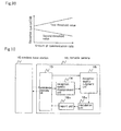
- FIG. 9 is an explanatory view showing an example of the relation between the communication volume information and threshold values. More specifically, FIG. 9A is an explanatory view showing an example of the relation between the number of connected users and the first threshold value and second threshold value. In FIG. 9A , the first threshold value decreases and the second threshold value increases as the number of connected users increases.
- FIG. 9B is an explanatory view showing an example of the relation between the amount of communication data and the first threshold value and second threshold value.
- the first threshold value decreases and the second threshold value increases as the amount of communication data decreases.
- communication processing unit 13 receives communication volume information relating to the amount of communication of wireless base station 10.
- Reception quality judgment unit 15 finds the first threshold value or the second threshold value or both the first and second threshold value based on the communication volume information received by communication processing unit 13.
- the first threshold value or the second threshold value or both the first and second threshold value are found based on the communication volume information.
- the PMI transmission volume can be adjusted according to the volume of communication of wireless base station 10.
- the communication volume information includes the number of terminal devices that are connected to the wireless base station 10 (number of connected users).
- the amount of PMI transmission of the entire wireless communication system increases and the interference of uplink lines increases as the number of connected users increases.
- the frequency bands for which individual PMI is individually computed decreases, whereby the amount of PMI transmission for the entire wireless communication system can be reduced and the interference of uplink lines can be reduced.
- the load placed upon portable terminal 11 can be reduced.
- the communication volume information includes the amount of information of signals transmitted by wireless base station 10 to the device in question (communication data volume).
- the computation of excessive PMI can be reduced when the amount of communication data is small, whereby the interference of uplink lines can be reduced.
- the load placed on portable terminal 11 can be reduced.
- FIG. 10 is a block diagram showing the configuration of the portable terminal of the present explanatory embodiment.
- portable terminal 11 includes: communication processing unit 13, reception quality measurement unit 14, reception quality judgment unit 15, calculation unit 16a, and report unit 16b.
- portable terminal 11 and wireless base station 10 can connect with each other.
- Communication processing unit 13 receives signals from wireless base station 10.
- Reception quality measurement unit 14 is an example of the measurement means. Reception quality measurement unit 14 measures reception quality of the signal received by communication processing unit 13 for each frequency band. The reception quality is, for example, a CQI.
- Reception quality judgment unit 15 determines, for each frequency band, whether the reception quality measured in reception quality measurement unit 14 is greater than a first threshold value.
- Calculation unit 16a computes a common PMI for frequency bands for which the reception quality has been determined in reception quality judgment unit 15 to be greater than the first threshold value. Calculation unit 16a further individually computes an individual PMI for each frequency band for which reception quality has been determined in reception quality judgment unit 15 to be equal to or less than the first threshold value.
- the PMI computation method is assumed to be identical to the first explanatory embodiment.
- FIG. 11 is an explanatory view showing an example of the frequency bands for which the common PMI and individual PMI are reported.
- an individual PMI is computed individually for each frequency band for which the reception quality is equal to or less than the first threshold value.
- a common PMI is computed that is common to these frequency bands.
- report unit 16b reports to wireless base station 10 the correspondence between frequency bands and the PMI that was computed by calculation unit 16a.
- report unit 16b reports to wireless base station 10 PMI report information that includes the PMI computed by calculation unit 16a and band information showing the frequency bands that correspond to these PMI numbers.
- reception quality judgment unit 15 executed Step S7 when the reception quality is equal to or less than the second threshold value in Step S5 of FIG. 5 .
- reception quality judgment unit 15 executes Step S8 when the reception quality is greater than the second threshold value.
- reception quality measurement unit 14 measures the reception quality of the signal received by communication processing unit 13 for each block frequency band.
- Reception quality judgment unit 15 determines for each block frequency band whether or not the reception quality is greater than the first threshold value or not.
- Calculation unit 16a individually computes an individual PMI for each frequency band for which the reception quality is equal to or less than the first threshold value. For frequency bands for which the reception quality is greater than the first threshold value, calculation unit 16a further computes a common PMI that is common to these frequency bands.
- Report unit 16b reports to the wireless base station the correspondence between the frequency bands and the individual PMI and common PMI that have been computed.
- the present invention can also be applied in wireless communication systems such as wireless LAN or portable telephone terminals such as portable telephones that employ FDM (Frequency Division Multiplexing) or OFDM in which precoding technology is applied.
- wireless communication systems such as wireless LAN or portable telephone terminals
- portable telephones such as portable telephones that employ FDM (Frequency Division Multiplexing) or OFDM in which precoding technology is applied.
- FDM Frequency Division Multiplexing
- OFDM Frequency Division Multiplexing
Landscapes
- Engineering & Computer Science (AREA)
- Computer Networks & Wireless Communication (AREA)
- Signal Processing (AREA)
- Mobile Radio Communication Systems (AREA)
Abstract
Description
- The present invention relates to a terminal device and a feedback method, and more particularly to a terminal device and feedback method for carrying out wireless communication using a precoding technology.
- In order to control wireless sources in frequency-selective channels in a wireless communication system that uses a multicarrier transmission mode such as OFDM (Orthogonal Frequency Division Multiplexing), terminals measure the reception quality of channels for each frequency band and report to the wireless base station a CQI (Channel Quality Indicator) that indicates this reception quality.
- When a terminal transmits a CQI for each frequency at this time, time is expended for the transmission of the CQI. The channel quality transmission method described in
Patent Document 1 is one technique for reducing the time expended in the transmission of CQI. - In this channel quality transmission method, the time taken for transmitting a CQI is reduced by collecting identical CQIs and transmitting them together.
Patent Document 1:JP-A-2007-166118 - In a wireless communication system such as LTE (Long Term Evolution), a precoding technique is applied before signal transmission to reduce the occurrence of data errors by compensating for distortion (characteristic) of a channel according to the channel condition.
- In the precoding technology, at the time of transmitting a signal to a terminal, the wireless base station multiplies the signal with a precoding matrix that indicates the inverse characteristics of the channel characteristics. The terminal carries out decoding after multiplying the signal that was received from the wireless base station with the inverse matrix of the precoding matrix. In this way, distortion of the channel can be compensated for and the occurrence of data errors can be reduced.
- The precoding matrix that is multiplied with the signal by the wireless base station is specified in the terminal. More specifically, the terminal calculates a PMI (Precoding Matrix Index) for specifying an appropriate precoding matrix based on the channel state of the subcarrier contained in the frequency band and a codebook that is prepared in advance. The codebook is information in which precoding matrices are placed in correspondence with each PMI.
- When a different precoding matrix is used for each frequency band in the precoding technology, the terminal separately calculates PMI for each frequency band, whereby distortion of the channels can be compensated for each of channels having mutually differing characteristics and reception quality can be improved.
- However, the load is increased in this case because the terminal calculates PMI separately for each frequency band.
- The following technology has been proposed for solving this problem.
- First, in 3GPP TSG RAN WGI Meeting #49 R1-072175, a method is proposed whereby a terminal calculates PMI only for frequency bands for which a CQI is reported to the wireless base station, as shown in
FIG. 1 . Here, a Best-M individual scheme is used as the method of reporting CQI. In the Best-M individual scheme, a terminal successively reports a predetermined number of CQIs from a frequency band having good reception quality. - The number of the PMI to be calculated can thus be reduced and the load of the terminal can thus be reduced.
- In addition to the above-described method, a method was further proposed in 3GPP TSG RAN WGI Meeting #49 bis R1-073082 in which a terminal alters the width of a frequency band for which PMI is calculated according to the reception quality, as shown in
FIG. 2 . For example, the terminal broadens frequency bands for which PMI is calculated as the reception quality increases. - In this way, the number of PMI to be calculated can be reduced, and the load of the terminal can thus be cut back.
- However, the two methods described above suffer from the problem of the large overhead expended in the process of calculating PMI. The reasons for this problem are next described.
- In the two methods described above, PMI is calculated individually for each frequency band even for frequency bands having good reception quality. When the reception quality is good, the efficiency of compensating for the channel characteristic is low even when individual precoding matrices are multiplied by the signal for each frequency band because the channel distortion is low from the start. As a result, the overhead expended in the PMI calculation process becomes high.
- In the method of 3GPP TSG RAN WGI Meeting #49 bis R1-073082, PMI is calculated individually for each of the frequency bands even for frequency bands having inferior reception quality. When the reception quality is inferior, the possibility of assigning that frequency band during signal transmission is low. As a result, the possibility of using a precoding matrix that is specified by that PMI is low even if the PMI is calculated. As a result, the overhead expended in the PMI calculation process becomes high.
- It is therefore an object of the present invention to provide a terminal device and feedback method that solves the above-described problem of increased overhead expended in the PMI calculation process.
- The terminal device according to the present invention includes: a reception means for receiving a signal from a wireless base station; a measurement means for measuring, for each of frequency bands that have been determined in advance, reception quality of a signal received by the reception means; a judgment means for judging, for each of the frequency bands, whether the reception quality measured by the measurement means is greater than a first threshold value; a calculation means for individually calculating, for each frequency band in which the reception quality is equal to or less than the first threshold value, an individual PMI for specifying a precoding matrix for compensating for channel distortion of that frequency band, and further, calculating, for frequency bands in which the reception quality is greater than the first threshold value, a common PMI for specifying a precoding matrix for compensating for channel distortion common to these frequency bands; and a report means for reporting to the wireless base station the correspondence between the frequency bands and the individual PMI and common PMI that were calculated in the calculation means.
- The feedback method according to the present invention is a feedback method carried out by a terminal device that can connect with a wireless base station and includes: a reception step of receiving a signal from the wireless base station; a measurement step of measuring, for each of the frequency bands that have been determined in advance, the reception quality of the received signal; a judgment step of judging, for each of the frequency bands, whether the measured reception quality is greater than a first threshold value or not; an individual calculation step of individually calculating for each of the frequency bands in which the reception quality is no greater than the first threshold value individual PMI for specifying a precoding matrix for compensating for channel distortion of that frequency band; a common calculation step of calculating, for frequency bands in which the reception quality is greater than the first threshold value, a common PMI for specifying a precoding matrix for compensating for common channel distortion for the frequency bands; and a reporting step of reporting to the wireless base station the correspondence between the individual PMI and common PMI that were calculated and the frequency bands.
- According to the present invention, overhead expended in the PMI calculation process can be reduced.
-
-
FIG. 1 is an explanatory view showing an example of frequency bands for which PMIs are reported; -
FIG. 2 is an explanatory view showing another example of frequency bands for which PMIs are reported; -
FIG. 3 is a block diagram showing the wireless communication system of the first explanatory embodiment of the present invention; -
FIG. 4 is an explanatory view showing an example of a frequency bands for which a common PMI and an individual PMI are reported; -
FIG. 5 is a flow chart for explaining an example of the operation ofportable terminal 11; -
FIG. 6 is an explanatory view showing another example of frequency bands for which a common PMI and individual PMI are reported; -
FIG. 7 is an explanatory view showing an example of PMI report information; -
FIG. 8 is a flow chart for explaining another example of the operation ofportable terminal 11; -
FIG. 9A is an explanatory view showing an example of the relation between the number of connected users and threshold values; -
FIG. 9B is an explanatory view showing an example of the relation between the amount of communication data and threshold values; -
FIG. 10 is a block diagram showing the configuration of a portable terminal of the fourth explanatory embodiment of the present invention; and -
FIG. 11 is an explanatory view showing another example of the frequency bands for which a common PMI and an individual PMI are reported. - An explanatory embodiment of the present invention is next described with reference to the accompanying figures.
-
FIG. 3 is a block diagram showing the wireless communication system of the first explanatory embodiment of the present invention. InFIG. 3 , the wireless communication system includeswireless base station 10 andportable terminal 11.Wireless base station 10 andportable terminal 11 can connect with each other wirelessly. -
Wireless base station 10 includescommunication processing unit 12. -
Communication processing unit 12 carries out processing relating to communication. - For example,
communication processing unit 12 receives PMI report information for reporting PMI fromportable terminal 11. In the present explanatory embodiment, the PMI report information is assumed to include band information indicating the frequency band and a PMI for specifying a precoding matrix for compensating for channel distortion of the frequency band. - In addition,
communication processing unit 12 sets a channel for each predetermined frequency band and uses this channel to transmit signals toportable terminal 11. - At this time, upon receiving PMI report information that includes band information that indicates the frequency band for transmitting the signal,
communication processing unit 12 multiplies the signal with the precoding matrix specified in the PMI included in the PMI report information and then transmits the multiplied signal. -
Communication processing unit 12 is also assumed to use MIMO (Multiple Input Multiple Output) to transmit signals. MIMO is a technology for using a plurality of antennas to transmit and receive signals. -
Portable terminal 11 includescommunication processing unit 13, reception quality measurement unit 14, receptionquality judgment unit 15, and PMI calculation &report unit 16. -
Communication processing unit 13 is one example of the reception means and carries out processing relating to communication. For example,communication processing unit 13 receives signals fromwireless base station 10. - Reception quality measurement unit 14 is one example of the measurement means. Reception quality measurement unit 14 measures, for each frequency band, the reception quality of the signal that is received by
communication processing unit 13. In the present explanatory embodiment, the reception quality is the CQI. However, the reception quality can be altered as appropriate and is not limited to CQI. For example, the reception quality may be the SNR (Signal to Noise Ratio) or CNR (Carrier to Noise Ratio). - Reception
quality judgment unit 15 judges, for each frequency band, whether the reception quality measured in reception quality measurement unit 14 is greater than a first threshold value or not. Receptionquality judgment unit 15 further determines, for each frequency band, whether the reception quality is greater than a second threshold value. Here, the second threshold value is lower than the first threshold value. In the present explanatory embodiment, the first threshold value and the second threshold value are assumed to be fixed values. - PMI calculation &
report unit 16 calculates the PMI, and further, reports the correspondence of the PMI and frequency bands towireless base station 10. More specifically, PMI calculation &report unit 16 includes calculation unit 16a andreport unit 16b, and each unit carries out the processes described below. - Calculation unit 16a calculates a PMI that is common to frequency bands for which the reception quality is determined in reception
quality judgment unit 15 to be greater than the first threshold value and frequency bands for which the reception quality is determined by receptionquality judgment unit 15 to be equal to or less than the second threshold value. This PMI is hereinbelow referred to as the common PMI. - Calculation unit 16a further individually calculates a PMI for each of frequency bands for which reception quality is determined by reception
quality judgment unit 15 to be equal to or less than the first threshold value, and moreover, greater than the second threshold value. These PMI are hereinbelow referred to as individual PMI. - More specifically, when the common PMI is calculated, reception quality measurement unit 14 estimates the subcarrier channel states contained in all frequency bands, and calculation unit 16a calculates the common PMI based on the estimated channel states.
- When calculating the individual PMI, calculation unit 16a extracts the channel states of subcarriers contained in the frequency bands that correspond to the individual PMI from the channel states of subcarriers contained in all frequency bands and calculates individual PMI based on the extracted channel states.
- More specifically, calculation unit 16a first uses
Equation 1 to calculate a metric MSE(Fi) for each precoding matrix Fi contained in a codebook that is held in advance. The codebook is information in which a precoding matrix is placed in correspondence with each PMI. -

Here, H is a channel estimation matrix that indicates the channel state, M is the number of transmission antennas ofwireless base station 10, ε is the transmission power ofwireless base station 10, and N is the noise power. In addition, ε/N is the SN ratio. If it is assumed that I is the identity matrix of M×M and A is a matrix, then: -

is the inverse matrix of A, and -

represents the conjugate transpose matrix of A. In addition, A represents a matrix. - The channel estimation matrix is a matrix having as components a channel estimate value for each subcarrier that corresponds to each of M transmission antennas. Each channel estimate value is a value indicating the channel state of a particular subcarrier that was transmitted by a particular transmission antenna.
- When calculating the common PMI, calculation unit 16a uses, as the channel estimation matrix, a matrix having as components the channel estimate values of each subcarrier contained in all frequency bands for each of the transmission antennas. As a result, the channel estimation matrix is a matrix of: [the number of subcarriers contained in all frequency bands] x M.
- In addition, when calculating an individual PMI, calculation unit 16a uses as the channel estimation matrix, a matrix having as components the channel estimate values of each subcarrier contained in the frequency band that corresponds to the individual PMI for each of the transmission antennas. As a result, the channel estimation matrix is a matrix of: [the number of subcarriers contained in the frequency band that corresponds to the individual PMI] x M.
- The channel estimate values, the number N of transmission antennas, transmission power ε, and SN ratio are measured in reception quality measurement unit 14.
- Calculation unit 16a uses
Equation 4 to calculate the PMI from within metric MSE(Fi). -

-
FIG. 4 is an explanatory view showing an example of the frequency band for which the common PMI and individual PMI are reported. InFIG. 4 , an individual PMI is individually calculated for each of the frequency bands for which the CQI is equal to or less than the first threshold value, and moreover, greater than the second threshold value. In addition, for the other frequency bands, the common PMI takes the place of the PMI of the frequency bands and an individual PMI is not calculated. A common PMI is calculated that is common to these frequency bands. - Returning to
FIG. 3 ,report unit 16b reports towireless base station 10 the correspondence between the frequency bands and the individual PMI and common PMI that were calculated by calculation unit 16a. For example,report unit 16b reports towireless base station 10 PMI report information that contains the PMI that was computed by calculation unit 16a and band information that indicates the frequency bands that correspond to the PMI. - The operation is next described.
-
FIG. 5 is a flow chart for explaining an example of the operation ofportable terminal 11. - In Step S1,
communication processing unit 13 receives a signal fromcommunication processing unit 12 ofwireless base station 10 and transmits this signal to reception quality measurement unit 14. - Reception quality measurement unit 14 measures, for each frequency band, the reception quality of the signal that was received by
communication processing unit 13. Reception quality measurement unit 14 generates quality information that places the reception quality in correspondence with each frequency band. - In addition, reception quality measurement unit 14 finds computation information that is used in the computation of the PMI. The computation information includes a channel estimation matrix, the transmission antenna number, the transmission power, and the SN ratio.
- Here, the channel estimation matrix is a matrix that has as components channel estimate values of each of the subcarriers that are included in all frequency bands corresponding to each of the transmission antennas. Reception quality measurement unit 14 further finds each channel estimate value based on pilot symbols contained in the signal from
wireless base station 10 and pilot symbols that are unique towireless base station 10. - Reception quality measurement unit 14 transmits the quality information and computation information to reception
quality judgment unit 15. Upon receiving the quality information and computation information, receptionquality judgment unit 15 executes Step S2. - In Step S2, reception
quality judgment unit 15 transmits the computation information to calculation unit 16a. - Calculation unit 16a, upon receiving the computation information, calculates the common PMI based on the computation information and the codebook.
- More specifically, calculation unit 16a first substitutes into
Equation 1 the channel estimation matrix, transmission antenna number, transmission power, and SN ratio in the computation information for each precoding matrix Fi contained in the codebook and calculates metric MSE(Fi). - Calculation unit 16a next uses
Equation 4 to find, as the common PMI, precoding matrix Fi that gives the minimum value among the traces or metric MSE(Fi). - Upon calculating the common PMI, calculation unit 16a transmits a start request indicating the start of determination to reception
quality judgment unit 15. Upon receiving the reception quality, receptionquality judgment unit 15 executes Step S3. - In Step S3, reception
quality judgment unit 15 selects band information in the reception information, and determines whether the reception quality that was placed in correspondence with the band information is greater than the first threshold value. Receptionquality judgment unit 15 here selects one item of band information from among the band information that has still not been selected. - Reception
quality judgment unit 15 executes Step S4 when the reception quality is greater than the first threshold value and executes Step S5 when the reception quality is equal to or less than the first threshold value. - In Step S4, reception
quality judgment unit 15 transmits the band information that was selected and superior information indicating that reception quality is superior to calculation unit 16a. Calculation unit 16a, having received the band information and superior information, generates PMI report information that includes the common PMI that was computed in Step S2 and the band information, and saves the PMI report information. Calculation unit 16a, after completing Step S4, executes Step S8. - Alternatively, in Step S5, reception
quality judgment unit 15 determines whether the reception quality that was placed in correspondence with the band information that was selected in Step S3 is greater than the second threshold value. Receptionquality judgment unit 15 executes Step S6 if the reception quality is greater than the second threshold value and executes Step S7 if the reception quality is equal to or less than the second threshold value. - In Step S6, reception
quality judgment unit 15 transmits to calculation unit 16a the selected band information and intermediate information indicating that the reception quality is intermediate. Upon receiving the band information and intermediate information, calculation unit 16a calculates individual PMI based on the computation information received in Step S2 and on the codebook. - More specifically, calculation unit 16a extracts from the channel estimation matrices in the computation information a partial matrix indicating the channel state of subcarriers contained in the frequency band that is indicated by the band information.
- Calculation unit 16a next substitutes into
Equation 1 the extracted partial matrix and the transmission antenna number, transmission power, and SN ratio in the computation information for each precoding matrix Fi contained in the codebook to calculate metric MSE(Fi). Calculation unit 16a here substitutes intoEquation 1 the partial matrix as the channel estimation matrix. - Calculation unit 16a then uses
Equation 4 to find, as the PMI, precoding matrix Fi that gives the minimum value among the traces or matrix expressions of metric MSE(Fi). - Upon computing the individual PMI, calculation unit 16a generates PMI report information that includes the individual PMI and band information and holds this PMI report information. After completing Step S6, calculation unit 16a executes Step S8.
- In Step S7, reception
quality judgment unit 15 transmits to calculation unit 16a the band information that was selected and inferior information indicating that the reception quality is inferior. Calculation unit 16a, having received the band information and inferior information, generates PMI report information that includes the common PMI that was calculated in Step S2 and the band information, and holds the PMI report information. After completing Step S7, calculation unit 16a executes Step S8. - In Step S8, calculation unit 16a transmits to reception
quality judgment unit 15 computation completion information indicating that the PMI has been computed. - Upon receiving the computation completion information, reception
quality judgment unit 15 determines whether or not all band information has been selected. Receptionquality judgment unit 15 executes Step S9 if all band information has been selected and executes Step S3 if unselected band information remains. - In Step S9, reception
quality judgment unit 15 transmits to calculation unit 16a report instructions indicating that PMI report information should be reported. - Upon receiving the report instructions, calculation unit 16a transmits the PMI report information to report
unit 16b.Report unit 16b, having received the PMI report information, transmits the PMI report information towireless base station 10 to complete the process. - In addition, Steps S1 to S9 may be repeated while
wireless base station 10 andportable terminal 11 are connected. - The effect is next described.
- In the present explanatory embodiment, reception quality measurement unit 14 measures the reception quality of a signal received by
communication processing unit 13 for each block frequency band. Receptionquality judgment unit 15 determines whether the reception quality is greater than a first threshold value for each block frequency band. Calculation unit 16a individually computes an individual PMI for each frequency band for which the reception quality is equal to or less than the first threshold value. Calculation unit 16a further computes, for frequency bands for which the reception quality is greater than the first threshold value, a common PMI that is shared among these frequency bands.Report unit 16b reports to the wireless base station the correspondence between the frequency bands and the individual PMI and common PMI that were computed. - In this case, for frequency bands in which the reception quality is greater than the first threshold value, a common PMI is computed that is shared among these frequency bands. The need for individually computing PMI for each of frequency bands in which reception quality is good is therefore eliminated, and the overhead expended for the PMI computation process can be reduced. Accordingly, the load upon
portable terminal 11 can be reduced, and, for example, the life of the power supply of portable terminal 11 can be extended. - In the present explanatory embodiment, reception
quality judgment unit 15 determines for each frequency band whether the reception quality is greater than a second threshold value that is lower than the first threshold value. Calculation unit 16a individually computes an individual PMI for each frequency band for which the reception quality is greater than the second threshold value. - In this case, an individual PMI is individually computed for each frequency band for which the reception quality is greater than the second threshold value.
- Eliminating the need to individually compute a PMI for each frequency band for which the reception quality is inferior enables a reduction of the overhead expended in the PMI computation process.
- In the present explanatory embodiment, calculation unit 16a computes, for frequency bands in which the reception quality is greater than the first threshold value and frequency bands in which the reception quality is equal to or less than the second threshold value, a common PMI that is common to these frequency bands.
- In this case, by computing only once a PMI that is common to frequency bands in which the reception quality is superior and to frequency bands in which the reception quality is inferior, a PMI can be computed for frequency bands in which the reception quality is inferior. Accordingly, a PMI can be computed for frequency bands in which the reception quality is inferior while reducing the overhead expended in the PMI computation process.
- The second explanatory embodiment is next described. The following explanation chiefly regards functions that differ from the first explanatory embodiment.
- In the present explanatory embodiment, calculation unit 16a computes PMI only for frequency bands for which reception
quality judgment unit 15 has determined that reception quality is greater than the second threshold value. - More specifically, calculation unit 16a individually computes an individual PMI for each frequency band for which the reception quality is equal to or less than the first threshold value and for each frequency band for which the reception quality is greater than the second threshold value. For frequency bands for which the reception quality is greater than the first threshold value, calculation unit 16a computes a common PMI that is common to these frequency bands. Calculation unit 16a then does not compute PMI for frequency bands for which the reception quality is equal to or less than the second threshold value.
-
FIG. 6 is an explanatory view showing an example of the frequency band for reporting the common PMI and individual PMI. InFIG. 6 , an individual PMI is individually computed for each frequency band for which the reception quality is equal to or less than the first threshold value, and moreover, for which the reception quality is greater than the second threshold value. For frequency bands for which the reception quality is greater than the first threshold value, a common PMI that is common to these frequency bands is computed. Finally, a PMI is not computed in frequency bands for which the reception quality is equal to or less than the second threshold value. - Accordingly, as in the first explanatory embodiment, the need to individually compute PMI is eliminated for each frequency band in which the reception quality is inferior, and the overhead expended for the PMI computation process can therefore be reduced.
- In the present explanatory embodiment,
report unit 16b reports the correspondence between the PMI and frequency bands by the following format. -
Report unit 16b transmits quality information, first threshold value, and second threshold value towireless base station 10.Report unit 16b further transmits information in which the PMI are arranged in a predetermined order as PMI report information. -
FIG. 7 is an explanatory view showing an example of the PMI report information. In the PMI report information inFIG. 7 , the common PMI is set as the first PMI and, in the second and succeeding PMI, individual PMI are arranged in order from the frequency band having the lowest frequency. -
Communication processing unit 12 ofwireless base station 10, upon receiving the quality information, first threshold value, second threshold value, and PMI report information, specifies the PMI of the frequency band for each frequency band based on the quality information, first threshold value, second threshold value, and PMI report information. - In the case of
FIG. 7 , for example,communication processing unit 12 first determines for each frequency band whether the reception quality is greater than the first threshold value or not based on the quality information received fromportable terminal 11.Communication processing unit 12 further determines for each frequency band whether the reception quality is greater than the second threshold value. -
Communication processing unit 12 then specifies the first PMI of the PMI report information as the PMI of frequency bands for which the reception quality is greater than the first threshold value.Communication processing unit 12 further successively specifies, as the PMI for frequency bands for which the reception quality is equal to or less than the first threshold value and moreover, greater than the second threshold value, PMI in order of lower frequency from the second PMI of the PMI report information. - Accordingly, the common PMI in all frequency bands need only be reported once, and the amount of PMI transmissions can therefore be reduced. As a result, interference can be reduced in all uplink lines.
- The operation is next described.
-
FIG. 8 is a flow chart for explaining an example of the operation ofportable terminal 11 of the present explanatory embodiment. InFIG. 8 , the same reference numbers are given to processes that are identical toFIG. 5 and redundant explanation of these processes is omitted. - In Step S3, reception
quality judgment unit 15 executes Step S8 when the reception quality is greater than the first threshold value and executes Step S5 when the reception quality is equal to or less than the first threshold value. - In Step S5, reception
quality judgment unit 15 executes Step S6' if the reception quality is greater than the second threshold value and executes Step S8 if the reception quality is equal to or less than the second threshold value. - In Step S6', reception
quality judgment unit 15 transmits to calculation unit 16a the selected band information and intermediate information indicating that the reception quality is intermediate. - Calculation unit 16a, upon receiving the band information and intermediate information, computes the individual PMI based on the computation information received in Step S2 and the codebook. Calculation unit 16a holds this individual PMI and the band information in mutual correspondence. Upon completion of Step S6', calculation unit 16a executes Step S8.
- Alternatively, when all band information has been selected in Step S8, reception
quality judgment unit 15 executes Step S9'. - In Step S9', reception
quality judgment unit 15 transmits report instructions to calculation unit 16a. - Upon receiving the report instructions, calculation unit 16a generates PMI report information based on the common PMI and PMI hold information. For example, calculation unit 16a first generates PMI report information that takes the common PMI computed in Step S2 as the first PMI. Calculation unit 16a next arranges the held individual PMI in order from the second item of PMI report information starting from the individual PMI that is placed in correspondence with band information that indicates the frequency band having the lowest frequency.
- When PMI report information has been generated, calculation unit 16a transmits the PMI report information to report
unit 16b.Report unit 16b, having received the PMI report information, transmits the PMI report information towireless base station 10. - The third explanatory embodiment is next described.
- In each of the above-described explanatory embodiments, the first threshold value and second threshold value are fixed values, but in the present explanatory embodiment, these values are found based on communication volume information that relates to the amount of communication of
wireless base station 10. - More specifically,
communication processing unit 12 ofwireless base station 10 transmits communication volume information toportable terminal 11. The communication volume information includes, for example, at least one of: the number of terminal devices connected to wireless base station 10 (hereinbelow also referred to as the number of connected users) and the information volume of signals thatwireless base station 10 transmits to its own device (portable terminal 11) (hereinbelow also referred to as the amount of communication data). -
Communication processing unit 13 ofportable terminal 11 receives the communication volume information fromwireless base station 10. - Reception
quality judgment unit 15 finds the first threshold value or the second threshold value or both the first and second threshold value based on the communication volume information received bycommunication processing unit 13. - For example, when the communication volume information is the number of connected users, reception
quality judgment unit 15 decreases the first threshold value and increases the second threshold value as the number of connected users increases. - If the communication volume information is the amount of communication data, reception
quality judgment unit 15 decreases the first threshold value and increases the second threshold value as the amount of information decreases. - Alternatively, reception
quality judgment unit 15 may also find the first threshold value and second threshold value independently, for example, finding the first threshold value based on the number of connected users and finding the second threshold value based on the amount of communication data. -
FIG. 9 is an explanatory view showing an example of the relation between the communication volume information and threshold values. More specifically,FIG. 9A is an explanatory view showing an example of the relation between the number of connected users and the first threshold value and second threshold value. InFIG. 9A , the first threshold value decreases and the second threshold value increases as the number of connected users increases. -
FIG. 9B is an explanatory view showing an example of the relation between the amount of communication data and the first threshold value and second threshold value. InFIG. 9A , the first threshold value decreases and the second threshold value increases as the amount of communication data decreases. - The effect is next described.
- In the present explanatory embodiment,
communication processing unit 13 receives communication volume information relating to the amount of communication ofwireless base station 10. Receptionquality judgment unit 15 finds the first threshold value or the second threshold value or both the first and second threshold value based on the communication volume information received bycommunication processing unit 13. - In this case, the first threshold value or the second threshold value or both the first and second threshold value are found based on the communication volume information. As a result, the PMI transmission volume can be adjusted according to the volume of communication of
wireless base station 10. - In the present explanatory embodiment, the communication volume information includes the number of terminal devices that are connected to the wireless base station 10 (number of connected users).
- Normally, the amount of PMI transmission of the entire wireless communication system increases and the interference of uplink lines increases as the number of connected users increases. In the present explanatory embodiment, if, for example, the first threshold value is decreased and the second threshold value is increased as the number of connected users increases, the frequency bands for which individual PMI is individually computed decreases, whereby the amount of PMI transmission for the entire wireless communication system can be reduced and the interference of uplink lines can be reduced. In addition, the load placed upon
portable terminal 11 can be reduced. - In the present explanatory embodiment, the communication volume information includes the amount of information of signals transmitted by
wireless base station 10 to the device in question (communication data volume). - In this case, if, for example, the first threshold value is decreased and the second threshold value is increased as the communication data volume decreases, the computation of excessive PMI can be reduced when the amount of communication data is small, whereby the interference of uplink lines can be reduced. In addition, the load placed on
portable terminal 11 can be reduced. - The fourth explanatory embodiment is next described.
- In the present explanatory embodiment, the simplest configuration of the portable terminal of the present invention is described.
-
FIG. 10 is a block diagram showing the configuration of the portable terminal of the present explanatory embodiment. InFIG. 10 ,portable terminal 11 includes:communication processing unit 13, reception quality measurement unit 14, receptionquality judgment unit 15, calculation unit 16a, andreport unit 16b. In addition,portable terminal 11 andwireless base station 10 can connect with each other. -
Communication processing unit 13 receives signals fromwireless base station 10. - Reception quality measurement unit 14 is an example of the measurement means. Reception quality measurement unit 14 measures reception quality of the signal received by
communication processing unit 13 for each frequency band. The reception quality is, for example, a CQI. - Reception
quality judgment unit 15 determines, for each frequency band, whether the reception quality measured in reception quality measurement unit 14 is greater than a first threshold value. - Calculation unit 16a computes a common PMI for frequency bands for which the reception quality has been determined in reception
quality judgment unit 15 to be greater than the first threshold value. Calculation unit 16a further individually computes an individual PMI for each frequency band for which reception quality has been determined in receptionquality judgment unit 15 to be equal to or less than the first threshold value. The PMI computation method is assumed to be identical to the first explanatory embodiment. -
FIG. 11 is an explanatory view showing an example of the frequency bands for which the common PMI and individual PMI are reported. InFIG. 11 , an individual PMI is computed individually for each frequency band for which the reception quality is equal to or less than the first threshold value. In addition, for frequency bands for which the reception quality is greater than the first threshold value, a common PMI is computed that is common to these frequency bands. - Returning to
FIG. 10 ,report unit 16b reports towireless base station 10 the correspondence between frequency bands and the PMI that was computed by calculation unit 16a. For example,report unit 16b reports towireless base station 10 PMI report information that includes the PMI computed by calculation unit 16a and band information showing the frequency bands that correspond to these PMI numbers. - Operation is next described.
- In the first explanatory embodiment, reception
quality judgment unit 15 executed Step S7 when the reception quality is equal to or less than the second threshold value in Step S5 ofFIG. 5 . In the present explanatory embodiment, receptionquality judgment unit 15 executes Step S8 when the reception quality is greater than the second threshold value. - The operations are otherwise identical to the first explanatory embodiment and further explanation is therefore omitted.
- The effect is next described.
- In the present explanatory embodiment, as in the first explanatory embodiment, reception quality measurement unit 14 measures the reception quality of the signal received by
communication processing unit 13 for each block frequency band. Receptionquality judgment unit 15 determines for each block frequency band whether or not the reception quality is greater than the first threshold value or not. Calculation unit 16a individually computes an individual PMI for each frequency band for which the reception quality is equal to or less than the first threshold value. For frequency bands for which the reception quality is greater than the first threshold value, calculation unit 16a further computes a common PMI that is common to these frequency bands.Report unit 16b reports to the wireless base station the correspondence between the frequency bands and the individual PMI and common PMI that have been computed. - As a result, the overhead expended for the PMI computation process can be reduced.
- Although the invention of the present application has been described above with reference to explanatory embodiments, the invention of the present application is not limited to the above-described explanatory embodiment. The configuration and details of invention of the present application are open to various modifications within the scope of the invention that will be understood by anyone of ordinary skill in the art.
- For example, although description regarded portable telephone terminals that use LTE in each of the explanatory embodiments, the present invention can also be applied in wireless communication systems such as wireless LAN or portable telephone terminals such as portable telephones that employ FDM (Frequency Division Multiplexing) or OFDM in which precoding technology is applied.
- This application claims priority based on
JP-2007-316054-A
Claims (16)
- A terminal device comprising:a reception means for receiving a signal from a wireless base station;a measurement means for measuring, for each of frequency bands that have been determined in advance, reception quality of the signal received by said reception means;a judgment means for determining, for each of said frequency bands, whether the reception quality measured by said measurement means is greater than a first threshold value;a calculation means for individually calculating, for each frequency band in which said reception quality is equal to or less than said first threshold value, an individual PMI for specifying a precoding matrix for compensating for channel distortion of that frequency band, and further, for frequency bands in which said reception quality is greater than said first threshold value, calculating a common PMI for specifying a precoding matrix for compensating for channel distortion common to those frequency bands; anda report means for reporting to said wireless base station the correspondence between said frequency bands and individual PMI and common PMI that were calculated in said calculation means.
- The terminal device as set forth in claim 1, wherein:said judgment means determines for each of said frequency bands whether reception quality measured by said measurement means is greater than a second threshold value that is less than said first threshold value; andsaid calculation means individually calculates said individual PMI for each frequency band wherein said reception quality is greater than said second threshold value.
- The terminal device as set forth in claim 2, wherein said calculation means calculates, for frequency bands in which said reception quality is greater than said first threshold value and for frequency bands in which where said reception quality is equal to or less than said second threshold value, said common PMI that is common to these frequency bands.
- The terminal device as set forth in any one of claims 1 to 3, wherein:said reception means receives from said wireless base station communication volume information that relates to the amount of communication of the wireless base station; andsaid judgment means finds said first threshold value based on said communication volume information.
- The terminal device as set forth in claim 2 or claim 3, wherein:said reception means receives from said wireless base station communication volume information relating to the amount of communication of said wireless base station; andsaid judgment means finds said second threshold value based on said communication volume information.
- The terminal device as set forth in claim 5, wherein said judgment means finds said first threshold value based on said communication volume information.
- The terminal device as set forth in any one of claims 4 to 6, wherein said communication volume information includes the number of terminal devices connected to said wireless base station.
- The terminal device as set forth in any one of claims 4 to 7, wherein said communication volume information includes the amount of information in signals transmitted by said wireless base station to the terminal device.
- A feedback method carried out by a terminal device that can connect to a wireless base station, comprising:a reception step of receiving a signal from said wireless base station;a measurement step of measuring, for each of frequency bands that have been determined in advance, the reception quality of said received signal;a judgment step of determining, for each of said frequency bands, whether or not said measured reception quality is greater than a first threshold value;an individual calculation step of individually calculating, for each of frequency bands in which said reception quality is equal to or less than said first threshold value, an individual PMI for specifying a precoding matrix for compensating for channel distortion of that frequency band;a common calculation step of calculating, for frequency bands, where said reception quality is greater than said first threshold value, a common PMI for specifying a precoding matrix for compensating for channel distortion common to those frequency bands; anda reporting step of reporting to said wireless base station the correspondence between said frequency bands and the individual PMI and common PMI that were calculated.
- The feedback method as set forth in claim 9, further comprising:a judgment step of determining, for each said frequency band, whether said measured reception quality is greater than a second threshold value that is smaller than said first threshold value;wherein, in said individual calculation step, said individual PMI is individually calculated for each frequency band where said reception quality is greater than said second threshold value.
- The feedback method as set forth in claim 10, wherein, in said common calculation step, said common PMI is calculated for frequency bands where said reception quality is greater than said first threshold value and is calculated for frequency bands where said reception quality is equal to or less than said second threshold value.
- The feedback method as set forth in any one of claims 9 to 11, further comprising:a reception step of receiving from said wireless base station communication volume information relating to the amount of communication of said wireless base station; anda first calculation step of finding said first threshold value based on said communication volume information.
- The feedback method as set forth in claim 10 or 11, further comprising:a reception step of receiving from said wireless base station communication volume information relating to the amount of communication of said wireless base station; anda second calculation step of finding said second threshold value based on said communication volume information.
- The feedback method as set forth in claim 13, further comprising a first calculation step of finding said first threshold value based on said communication volume information.
- The feedback method as set forth in any one of claims 12 to 14, wherein said communication volume information includes the number of terminal devices connected to said wireless base station.
- The feedback method as set forth in any one of claims 12 to 15, wherein said communication volume information includes the amount of information transmitted by said wireless base station to the terminal device.
Applications Claiming Priority (2)
| Application Number | Priority Date | Filing Date | Title |
|---|---|---|---|
| JP2007316054 | 2007-12-06 | ||
| PCT/JP2008/071286 WO2009072408A1 (en) | 2007-12-06 | 2008-11-25 | Terminal device and feedback method |
Publications (2)
| Publication Number | Publication Date |
|---|---|
| EP2222108A1 true EP2222108A1 (en) | 2010-08-25 |
| EP2222108A4 EP2222108A4 (en) | 2016-11-09 |
Family
ID=40717590
Family Applications (1)
| Application Number | Title | Priority Date | Filing Date |
|---|---|---|---|
| EP08856015.6A Withdrawn EP2222108A4 (en) | 2007-12-06 | 2008-11-25 | TERMINAL DEVICE AND FEEDBACK METHOD |
Country Status (5)
| Country | Link |
|---|---|
| US (1) | US8406186B2 (en) |
| EP (1) | EP2222108A4 (en) |
| JP (1) | JP5234007B2 (en) |
| CN (1) | CN101889460B (en) |
| WO (1) | WO2009072408A1 (en) |
Families Citing this family (7)
| Publication number | Priority date | Publication date | Assignee | Title |
|---|---|---|---|---|
| JP5381405B2 (en) * | 2009-06-30 | 2014-01-08 | 富士通株式会社 | Wireless communication system, wireless communication device, and control device |
| JP5489210B2 (en) * | 2009-10-26 | 2014-05-14 | 日本電気株式会社 | Receiving apparatus, receiving method, and program |
| US8374100B2 (en) * | 2009-12-24 | 2013-02-12 | Intel Corporation | Method and system for multiband rate scaling |
| CN107070507B (en) | 2010-01-08 | 2021-02-26 | 太阳专利信托公司 | Communication device and communication method |
| US20140086190A1 (en) * | 2011-05-10 | 2014-03-27 | Ntt Docomo, Inc. | Mobile station device, communication method, and computer program |
| CN116938401A (en) * | 2022-03-31 | 2023-10-24 | 华为技术有限公司 | Data transmission method and communication device |
| WO2025208422A1 (en) * | 2024-04-03 | 2025-10-09 | Oppo广东移动通信有限公司 | Measurement information sending method and apparatus, device, and storage medium |
Family Cites Families (9)
| Publication number | Priority date | Publication date | Assignee | Title |
|---|---|---|---|---|
| JP4173293B2 (en) * | 2001-08-28 | 2008-10-29 | 株式会社エヌ・ティ・ティ・ドコモ | Mobile communication system, base station, radio network controller, mobile station, and mobile station power consumption reduction method |
| JP2004140674A (en) | 2002-10-18 | 2004-05-13 | Fujitsu Ltd | Handoff control method and device in portable terminal |
| JP3963464B2 (en) | 2004-02-24 | 2007-08-22 | 株式会社東芝 | Wireless communication apparatus and frequency channel selection method |
| JP4663369B2 (en) * | 2004-05-20 | 2011-04-06 | パナソニック株式会社 | Wireless communication system, wireless communication method, base station apparatus, and terminal apparatus |
| BRPI0515173A (en) | 2004-09-08 | 2008-07-08 | Matsushita Electric Industrial Co Ltd | wireless transmission apparatus and method for pre-equalizing it |
| JP4684071B2 (en) * | 2005-05-20 | 2011-05-18 | 株式会社エヌ・ティ・ティ・ドコモ | Cell search control method and mobile device using the method |
| JP2007166118A (en) | 2005-12-12 | 2007-06-28 | Mitsubishi Electric Corp | Channel quality transmission method and terminal |
| EP2130308B1 (en) * | 2007-03-22 | 2018-12-19 | Marvell World Trade Ltd. | Variable codebook for mimo system |
| US20080268785A1 (en) * | 2007-04-30 | 2008-10-30 | Mccoy James W | UE-autonomous CFI reporting |
-
2008
- 2008-11-25 WO PCT/JP2008/071286 patent/WO2009072408A1/en not_active Ceased
- 2008-11-25 US US12/742,034 patent/US8406186B2/en active Active
- 2008-11-25 JP JP2009544633A patent/JP5234007B2/en active Active
- 2008-11-25 CN CN2008801196341A patent/CN101889460B/en not_active Expired - Fee Related
- 2008-11-25 EP EP08856015.6A patent/EP2222108A4/en not_active Withdrawn
Non-Patent Citations (1)
| Title |
|---|
| See references of WO2009072408A1 * |
Also Published As
| Publication number | Publication date |
|---|---|
| JP5234007B2 (en) | 2013-07-10 |
| JPWO2009072408A1 (en) | 2011-04-21 |
| WO2009072408A1 (en) | 2009-06-11 |
| EP2222108A4 (en) | 2016-11-09 |
| CN101889460B (en) | 2013-05-01 |
| CN101889460A (en) | 2010-11-17 |
| US8406186B2 (en) | 2013-03-26 |
| US20100265837A1 (en) | 2010-10-21 |
Similar Documents
| Publication | Publication Date | Title |
|---|---|---|
| EP2174428B1 (en) | Method and system for operating a multi-user multiple-input multiple-output (mu-mimo) wireless communications system | |
| US9100169B2 (en) | System and method for channel state information feedback in wireless communications systems | |
| EP2648445B1 (en) | Method and device for reporting channel state | |
| EP2692070B1 (en) | Method and user equipment of feeding back mu-cqi in a communication system | |
| EP2127222B1 (en) | Transmitting and receiving channel quality information- and precoding matrix index-feedback information | |
| US8406186B2 (en) | Terminal device and feedback method | |
| EP2410785B1 (en) | Method and device for estimating downlink channel quality | |
| EP2648443B1 (en) | Method for reporting channel quality information and device thereof | |
| EP2811661B1 (en) | Precoding in a MIMO communication system based on delayed PMI information | |
| EP2637435A1 (en) | Method and device for reporting channel quality information | |
| CN103580739B (en) | Channel quality indication (CQI) information reports and determines method and apparatus | |
| US20140301232A1 (en) | Apparatus and method for csi calculation and reporting | |
| EP2448137A1 (en) | Method and device for signal transmission in time-division duplex mimo system | |
| CN102546110A (en) | Channel state information transmission method and device | |
| US20100067616A1 (en) | Method of transmitting control information in multiple antenna system | |
| CN103580779B (en) | Channel quality instruction information reporting and determining method and equipment | |
| WO2012020312A2 (en) | A method and device for obtaining enhanced channel quality indicator | |
| CN102237955A (en) | Channel state information reporting method and device | |
| US9615280B2 (en) | Calculating and reporting channel characteristics | |
| CN104579544A (en) | CQI or RI selection method and system under LTE TM3 mode |
Legal Events
| Date | Code | Title | Description |
|---|---|---|---|
| PUAI | Public reference made under article 153(3) epc to a published international application that has entered the european phase |
Free format text: ORIGINAL CODE: 0009012 |
|
| 17P | Request for examination filed |
Effective date: 20100621 |
|
| AK | Designated contracting states |
Kind code of ref document: A1 Designated state(s): AT BE BG CH CY CZ DE DK EE ES FI FR GB GR HR HU IE IS IT LI LT LU LV MC MT NL NO PL PT RO SE SI SK TR |
|
| AX | Request for extension of the european patent |
Extension state: AL BA MK RS |
|
| DAX | Request for extension of the european patent (deleted) | ||
| RAP1 | Party data changed (applicant data changed or rights of an application transferred) |
Owner name: LENOVO INNOVATIONS LIMITED (HONG KONG) |
|
| RA4 | Supplementary search report drawn up and despatched (corrected) |
Effective date: 20161010 |
|
| RIC1 | Information provided on ipc code assigned before grant |
Ipc: H04J 99/00 20090101ALI20161004BHEP Ipc: H04W 88/02 20090101ALI20161004BHEP Ipc: H04W 24/10 20090101AFI20161004BHEP |
|
| STAA | Information on the status of an ep patent application or granted ep patent |
Free format text: STATUS: EXAMINATION IS IN PROGRESS |
|
| 17Q | First examination report despatched |
Effective date: 20180215 |
|
| STAA | Information on the status of an ep patent application or granted ep patent |
Free format text: STATUS: THE APPLICATION IS DEEMED TO BE WITHDRAWN |
|
| 18D | Application deemed to be withdrawn |
Effective date: 20180626 |