EP2222099B1 - Verfahren, einrichtung und system zur wiederherstellung nach desastern und handover-steuerung - Google Patents
Verfahren, einrichtung und system zur wiederherstellung nach desastern und handover-steuerung Download PDFInfo
- Publication number
- EP2222099B1 EP2222099B1 EP08851079A EP08851079A EP2222099B1 EP 2222099 B1 EP2222099 B1 EP 2222099B1 EP 08851079 A EP08851079 A EP 08851079A EP 08851079 A EP08851079 A EP 08851079A EP 2222099 B1 EP2222099 B1 EP 2222099B1
- Authority
- EP
- European Patent Office
- Prior art keywords
- disaster recovery
- switchover
- server
- threshold
- disaster
- Prior art date
- Legal status (The legal status is an assumption and is not a legal conclusion. Google has not performed a legal analysis and makes no representation as to the accuracy of the status listed.)
- Not-in-force
Links
Images




Classifications
-
- H—ELECTRICITY
- H04—ELECTRIC COMMUNICATION TECHNIQUE
- H04L—TRANSMISSION OF DIGITAL INFORMATION, e.g. TELEGRAPHIC COMMUNICATION
- H04L43/00—Arrangements for monitoring or testing data switching networks
- H04L43/16—Threshold monitoring
-
- H—ELECTRICITY
- H04—ELECTRIC COMMUNICATION TECHNIQUE
- H04L—TRANSMISSION OF DIGITAL INFORMATION, e.g. TELEGRAPHIC COMMUNICATION
- H04L41/00—Arrangements for maintenance, administration or management of data switching networks, e.g. of packet switching networks
- H04L41/06—Management of faults, events, alarms or notifications
- H04L41/0654—Management of faults, events, alarms or notifications using network fault recovery
- H04L41/0663—Performing the actions predefined by failover planning, e.g. switching to standby network elements
-
- H—ELECTRICITY
- H04—ELECTRIC COMMUNICATION TECHNIQUE
- H04L—TRANSMISSION OF DIGITAL INFORMATION, e.g. TELEGRAPHIC COMMUNICATION
- H04L67/00—Network arrangements or protocols for supporting network services or applications
- H04L67/01—Protocols
- H04L67/10—Protocols in which an application is distributed across nodes in the network
- H04L67/1001—Protocols in which an application is distributed across nodes in the network for accessing one among a plurality of replicated servers
-
- H—ELECTRICITY
- H04—ELECTRIC COMMUNICATION TECHNIQUE
- H04L—TRANSMISSION OF DIGITAL INFORMATION, e.g. TELEGRAPHIC COMMUNICATION
- H04L67/00—Network arrangements or protocols for supporting network services or applications
- H04L67/2866—Architectures; Arrangements
- H04L67/30—Profiles
-
- H—ELECTRICITY
- H04—ELECTRIC COMMUNICATION TECHNIQUE
- H04L—TRANSMISSION OF DIGITAL INFORMATION, e.g. TELEGRAPHIC COMMUNICATION
- H04L69/00—Network arrangements, protocols or services independent of the application payload and not provided for in the other groups of this subclass
- H04L69/40—Network arrangements, protocols or services independent of the application payload and not provided for in the other groups of this subclass for recovering from a failure of a protocol instance or entity, e.g. service redundancy protocols, protocol state redundancy or protocol service redirection
Definitions
- the present invention relates to communication technology, and in particular, to a method, system and device for processing disaster recovery switchover.
- Intelligent Network evolved from the telephone network which is composed of exchange nodes, Signal System #7 and service control computer, refers to an intelligent telephone network or an integrated service digital network. Its network intelligence configuration is distributed in computers among several Service Control Points (SCPs) in a whole network and more flexible network intelligence control is implemented by software.
- SCPs Service Control Points
- Intelligent Network is a service control network which is constructed over a switching network.
- SCP Service Control Points
- SSP Service triggering point
- Soft Switching Service Switching Points
- FIG. 1 is a schematic view of a conventional solution for processing disaster recovery switchover
- DRSCP Disaster Recovery Service Control Points
- production SCPs on a control layer are backed up in the DRSCP; when the production SCPs encounter a disaster, the SSP switches and connects to the DRSCP and sends signals to the DRSCP; SSP services are processed by the DRSCP to implement the disaster recovery processing of the SCP.
- the SSP detects on the switching layer whether the connection between the SSP and SCP is normal or not. If abnormal, the SSP forwards the signals to the DRSCP via standby signal points, Global Title (GT) translation and etc. Because in the network multiple SSPs are configured with one SCP, the SSPs are independent of each other, it is possible that one of the SSPs sends the signals to the DRSCP and others send the signals to the production SCP due to intermittent interruption of the link between the production SCP and SSP.
- GT Global Title
- the difference of network call traffic between busy state and idle state is great, and therefore upon receiving a signal message, the DRSCP needs to determine whether to perform the disaster recovery switchover according to the received SSP signals, so as to avoid the case that the SSPs send, due to the intermittent interruption of link between the SCP and one SSP in the case of busy network, the signals to the DRSCP to make the DRSCP inappropriately triggers the disaster recovery switchover.
- the issue that how the DRSCP makes a decision according to the signal message received from the SSP is the precondition of accurately performing the disaster recovery switchover.
- a conventional method of making the decision by the DRSCP is illustrated as follows in combination with Figure 2 .
- the DRSCP is provided with a disaster recovery detection module and a service control module of the DRSCP.
- the disaster recovery detection module analyzes the received signals and if it is detected that
- the signal address received is identical to that configured on the DRSCP, correct signals are received and then the service control module of the DRSCP is started to take over the services. Further, the service control module is started to process services of the SSPs.
- the disaster recovery detection module of the DRSCP triggers the disaster recovery switchover immediately upon receiving the signals from the SSPs, such condition for triggering the disaster recovery switchover is too sensitive. If the call traffic is large in the case of a busy network and the link between the SSPs and SCP is intermittently interrupted, the SSPs may send the signals to the DRSCP to trigger the disaster recovery switchover immediately, which is an inappropriately triggered disaster recovery switchover.
- a WO application ( WO 2006/120462 A1 ) discloses a controller for controlling the admit rate of messages passed to node in a communications system according to a control value that controls the maximum average admit rate, including the steps of periodically updating the control value in which the updated control value is the lesser of an increasing function of the previous control value; and an increasing function of the previous admit rate.
- a US application discloses a server.
- the server includes a scenario table in which object to-be-monitored information that indicates one or more network devices A, B, and C being objects for failure recovery, failure information for identifying contents of failures, countermeasure information against failures , and frequence information that indicates the number of times of the recoveries from the failures based on the countermeasure information are corresponding stored.
- the network device A detects the failure of the network device itself and transmits a failure event to the server.
- the server selects the countermeasure information item in descending order of the frequence information items, by reference to the scenario table, and transmits the selected countermeasure information item to the network device A.
- the server repeats the selections and transmissions of the pertinent information item until the reception of the failure event from the network device A stops.
- a US application discloses a communication state management system for managing a state of a communication using an intelligent network which provides a service to convert a predetermined number which is preregistered into a number identifying a terminal as a destination, comprising: a plurality of service switching points(SSPs), each of said SSPs accommodating one or more terminals; a service control point (SCP) for receiving a predetermined number which is preregistered and information identifying an SSP which outputs the predetermined number from at least one of said plurality of SSPs, storing a number identifying a terminal obtained from the received predetermined number, a communication state of the terminal, and the received information identifying the SSP in a communication state management table by making a correspondence between them, and controlling the communication state by using the communication state management table, wherein said SCP updates communication states for all of the terminals accommodated in the SSP of the communication state management table when trouble relating to one of said plurality of SSPs occurs.
- SSPs service switching points
- a US application discloses a method of real-time monitoring of operational status of an element of a communications network, comprising : receiving alarm or other operational status messages produced by the network element for a local log function, in real-time as the element generates the messages, via a streaming communication session, parsing each of the received messages to extract relevant operational data; populating fields of records in a database with the data extracted by the parsing; and providing a real-time display based on the received messages.
- a method for processing disaster recovery switchover includes:
- a device for processing disaster recovery switchover includes:
- An application server includes:
- a device for processing disaster recovery switchover includes:
- a disaster recovery server includes:
- a system for processing disaster recovery switchover includes:
- a method for processing disaster recovery switchover includes:
- the disaster recovery switchover may be provided with a reliable detection, decision processing by allowing the disaster recovery server to determine the disaster recovery switchover threshold and perform the disaster recovery switchover by use of the disaster recovery switchover threshold.
- a method for processing SCP disaster recovery switchover includes: determining, by a disaster recovery server, a disaster recovery switchover threshold; and performing disaster recovery switchover if the disaster recovery server determines to trigger the disaster recover switchover according to the number of signals sent by application triggering equipment and the determined disaster recovery switchover threshold.
- the process of determining the disaster recovery switchover threshold includes: determining the disaster recovery switchover threshold according to obtained processing capability information of an application server; or presetting a static disaster recovery switchover threshold.
- the disaster recovery server may determine the disaster recovery switchover threshold according to the obtained processing capability information of the application server in an Intelligent Network and a preset disaster recovery switchover threshold percentage. Particularly, a multiply product of the processing capability and the threshold percentage is the disaster recovery switchover threshold.
- the static disaster recovery switchover threshold may be set to the number of signals received per minute. When the number of the signals received by the disaster recovery server per minute reaches or exceeds the static disaster recovery switchover threshold, the disaster recovery switchover is triggered.
- An embodiment of the present invention provides a method for processing disaster recovery switchover for performing disaster recovery switchover in the case of fault of an application server in the network.
- the method includes:
- the disaster recovery processing may be performed by disposing a disaster recovery server 300.
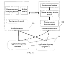
- the system for processing disaster recovery switchover as shown in Figure 3a includes an application server 310, application triggering equipment 320 and the disaster recovery server 300.
- the application triggering equipment 320 is configured to receive service signals sent by users, and send the service signals to the application server 310.
- the application server 310 is configured to provide related services according to the service signals.
- the application triggering equipment 320 may send the service signals to the disaster recovery server 300.
- the disaster recovery switchover may be performed if the disaster recovery server 300 determines, according to the number of the service signals and disaster disaster recovery switchover threshold, to trigger the disaster recovery switchover. In other words, related services are provided by the disaster recovery server 300.
- the application server 310 is further configured to obtain processing capability information of the application server 310, and send the processing capability information to the disaster recovery server 300.
- the application triggering equipment 320 is configured to send signals to the disaster recovery server 300.
- the disaster recovery server 300 is configured to receive the signals sent by the application triggering equipment 320, make statistics of the received signals, determine the disaster recovery switchover threshold according to the processing capability information of the application server 310, and perform the disaster recovery switchover if determining, according to the statistics result and the disaster recovery switchover threshold, to trigger the disaster recovery switchover.
- FIG. 5 a detailed structure of an apparatus which is disposed in the application server, for processing the disaster recovery switchover is illustrated as in Figure 5 .
- FIGs 6 and 7 A detailed structure of an apparatus which is disposed in the disaster recovery server, for processing the disaster recovery switchover is illustrated as in Figures 6 and 7 . These two structures are not repeated here again.
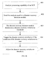
- the disaster recovery server may further include a switchover threshold adjustment module, and a detailed structure of an apparatus which is disposed in the disaster recovery server, for processing the disaster recovery switchover is illustrated as in Figure 9 .
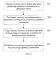
- FIG. 3b a flow chart for illustrating working principles of the system shown in Figure 3a is illustrated, in which the method for processing the disaster recovery switchover includes as follows:
- the method may further include the following step:
- step 302 above may be detailed as follows:
- a minimum switchover threshold is preset on the basis of the step 302. If the disaster recovery server 300 determines that the dynamic disaster recovery switchover threshold determined according to the processing capability information of the application server 310 is smaller than the preset minimum switchover threshold, the preset minimum switchover threshold is set to be an actual disaster recovery switchover threshold; otherwise, the dynamic disaster recovery switchover threshold is set to be an actual disaster recovery switchover threshold.
- the disaster recovery server performs disaster recovery switchover further when determining to trigger the disaster recovery switchover according to the number of signals received from the application triggering equipment and the minimum switchover threshold, which prevents inappropriate triggering of the disaster recovery switchover due to its sensitivity.
- the dynamic disaster recovery switchover threshold is set to be the actual disaster recovery switchover threshold
- the disaster recovery server performs disaster recovery switchover further when determining to trigger the disaster recovery switchover according to the number of signals received from the application triggering equipment and the dynamic disaster recovery switchover threshold.
- the application triggering equipment in this embodiment is SSP
- the application triggering equipment is SoftSwitch, SCP etc
- the disaster recovery process of this invention is the same as the case that the application triggering equipment is SSP.
- FIG. 4a a structural view of a system for processing disaster recovery switchover in an Intelligent Network is illustrated.
- an SSP 420 acting as application triggering equipment sends a signal to the production SCP 410, and a service control module 413 of the SCP processes the service.
- a disaster recovery analysis module 411 is added at the production SCP 410, and a disaster recovery decision module 401 is added at a DRSCP 400 acting as a disaster recovery server.
- a flow chart for illustrating working principles of the system shown in Figure 4a is illustrated. The method includes the following steps:
- the disaster recovery decision module 401 at the DRSCP 400 may also configure a minimum switchover threshold. If the disaster recovery switchover threshold determined dynamically by the disaster recovery decision module 401 according to the processing capability and the percentage of the switchover threshold current production SCP 410 is smaller than the minimum switchover threshold preset by the DRSCP 400, the minimum switchover threshold preset by the DRSCP 400 is taken as a threshold for triggering the disaster recovery switchover; otherwise, the disaster recovery switchover threshold dynamically determined is taken as a threshold for triggering the disaster recovery switchover.
- Such setting manner of the minimum switchover threshold may overcome the sensitivity of the disaster recovery switchover in the case of idle network, so as to avoid inappropriate triggering of the disaster recovery switchover.
- an apparatus for processing disaster recovery switchover is provided in an embodiment of the present invention.
- the apparatus may be arranged in an application server (310 or 410) in an Intelligent Network, or may be arranged separately from the application server (310 or 410).
- the apparatus includes a disaster recovery analysis module 500 and a sending module 510.
- the disaster recovery analysis module 500 is configured to obtain processing capability information of an application server. Specifically, the disaster recovery analysis module 500 may, periodically or irregularly analyzes the processing capability of the application server, and sends obtained processing capability information to a disaster recovery server via the sending module 510.
- the sending module is configured to send the processing capability information of the application server to the disaster recovery server.
- the application server (310 or 410) may further include a service control module, configured to receive service signals and provide the services.
- the apparatus may be arranged in a disaster recovery server (300 or 400) in an Intelligent Network, or may be arranged separately from the disaster recovery server (300 or 400).
- the apparatus includes a disaster recovery detection module 600 and a disaster recovery decision module 610.
- the disaster recovery detection module 600 is configured to receive signals sent by application triggering equipment, and make statistics of the number of the received signals.
- the application triggering equipment is connected with the application server and the disaster recovery server. When a fault occurs in the application server or the link between each application triggering equipment and the application server is faulty, the application triggering equipment may send signals to the disaster recovery server.
- the disaster recovery detection module 600 receives and makes statistics of the number of the signals sent from the application triggering equipment to obtain a statistics result, for example, the number of signals that the disaster recovery server receives per second in average.
- the disaster recovery decision module 610 is configured to determine a disaster recovery switchover threshold according to the processing capability information of the application server, and perform the disaster recovery switchover if determining, according to the statistics result (the number of the signals) from the disaster recovery detection module 600 and the disaster recovery switchover threshold, that the disaster recovery switchover needs to be triggered, for example, the statistics result reaches or exceeds the disaster recovery switchover threshold.
- the disaster recovery server (300 or 400) may further include a service control module, configured to provide services after the disaster recovery decision module determiners to trigger the disaster recovery switchover.
- a disaster recovery decision module 700 in the apparatus for processing disaster recovery switchover includes: a receiving sub-module 701, a decision sub-module 702, and a switching sub-module.
- the receiving sub-module 701 is configured to receive and store the processing capability information of the application server.
- the decision sub-module is configured to preset the static disaster recovery switchover threshold or determine the disaster recovery switchover threshold according to the processing capability information received by the receiving sub-module; and determine whether to trigger the disaster recovery switchover according to the number of the signals according to the statistics result from the disaster detection module and the determined disaster recovery switchover threshold.
- the switching sub-module is configured to perform the disaster recovery switchover according to the determination result from the decision sub-module.
- the apparatus for processing disaster recovery switchover as shown in Figure 6 further includes a switchover threshold adjustment module, configured to set the minimum switchover threshold to be the disaster recovery switchover threshold if the determined disaster recovery switchover threshold, for example, the disaster recovery switchover threshold obtained dynamically according to the processing capability information of the application server, is smaller than a minimum switchover threshold.
- a switchover threshold adjustment module configured to set the minimum switchover threshold to be the disaster recovery switchover threshold if the determined disaster recovery switchover threshold, for example, the disaster recovery switchover threshold obtained dynamically according to the processing capability information of the application server, is smaller than a minimum switchover threshold.
- a software product which may be stored in a computer-readable storage medium, such as a Read-Only Memory/Random Access Memory (ROM/RAM), a magnetic disk, and a compact disk.
- the software product includes a number of instructions that enable a computer device, which may be a personal computer, a server or a network device, to execute the method according to the embodiments of the invention or a certain part of an embodiment of the invention.
- the processing capability information is taken as a decision basis for the disaster recovery switchover to dynamically adjust the disaster recovery switchover threshold as the disaster recovery switchover threshold varies.
- This avoids the problems of inappropriate switchover in the case of busy network and no switchover in the case of idle network, and ensures the accuracy of triggering the disaster recovery switchover and prompt processing of related services.
- This method offers a reliable detection and decision mechanism for the disaster recovery switchover triggered by the signal so that the disaster recovery decision is not merely made depending on the static switchover threshold.
- the disaster recovery decision made in combination with the processing capability information of the production SCP so as to dynamically adjust the disaster recovery switchover threshold, thereby ensuring the accuracy and validity of the disaster recovery switchover.
Landscapes
- Engineering & Computer Science (AREA)
- Computer Networks & Wireless Communication (AREA)
- Signal Processing (AREA)
- Computer Security & Cryptography (AREA)
- Data Exchanges In Wide-Area Networks (AREA)
- Hardware Redundancy (AREA)
- Telephonic Communication Services (AREA)
- Mobile Radio Communication Systems (AREA)
Claims (6)
- Verfahren zum Verarbeiten eines Disaster-Recovery-Überwechsels, gekennzeichnet durch die folgenden Schritte:Empfangen und Speichern (301) der Verarbeitungsfähigkeitsinformationen eines Anwendungsservers durch einen Disaster-Recovery-Server;Bestimmen (302) einer Disaster-Recovery-Überwechselschwelle durch den Disaster-Recovery-Server; undDurchführen (303) eines Disaster-Recovery-Überwechsels, wenn der Disaster-Recovery-Server bestimmt, den Disaster-Recovery-Überwechsel zu triggern, um den Anwendungsserver zu ersetzen, um Dienste der Anwendungstriggergeräte gemäß der Anzahl der durch Anwendungstriggergeräte gesendeten Signale und der bestimmten Disaster-Recovery-Überwechselschwelle zu verarbeiten.
- Verfahren nach Anspruch 1, dadurch gekennzeichnet, dass der Prozess des Bestimmens der Disaster-Recovery-Überwechselschwelle Folgendes umfasst:Bestimmen der Disaster-Recovery-Überwechselschwelle gemäß erhaltenen Verarbeitungsfähigkeitsinformationen des Anwendungsservers; oderVoreinstellen einer statischen Disaster-Recovery-Überwechselschwelle.
- Verfahren nach einem der Ansprüche 1 bis 2, dadurch gekennzeichnet, dass der Prozess des Bestimmens einer Disaster-Recovery-Überwechselschwelle gemäß erhaltenen Verarbeitungsfähigkeitsinformationen eines Anwendungsservers Folgendes umfasst:Bestimmen der Disaster-Recovery-Überwechselschwelle durch den Disaster-Recovery-Server gemäß einem Produkt eines voreingestellten Schwellenprozentsatzes und den Verarbeitungsfähigkeitsinformationen des Anwendungsservers.
- Verfahren nach einem der Ansprüche 1 bis 3, dadurch gekennzeichnet, dass das Verfahren vor dem Prozess des Bestimmens, den Disaster-Recovery-Überwechsel zu triggern, ferner Folgendes umfasst:Setzen einer minimalen Überwechselschwelle als die Disaster-Recovery-Überwechselschwelle durch den Disaster-Recovery-Server, wenn die bestimmte Disaster-Recovery-Überwechselschwelle kleiner als die minimale Überwechselschwelle ist.
- Anwendungsserver, dadurch gekennzeichnet, dass er Folgendes umfasst:ein Serversteuermodul (413), das dafür ausgelegt ist, Signale von einem Anwendungstriggergerät zu empfangen und die Dienste bereitzustellen;ein Disaster-Recovery-Analysemodul (411, 500), das dafür ausgelegt ist,Verarbeitungsfähigkeitsinformationen eines Anwendungsservers zu erhalten, wobei die Verarbeitungsfähigkeitsinformationen des Anwendungsservers für ein Disaster-Recovery verwendet werden, um eine Disaster-Recovery-Überwechselschwelle zu bestimmen; undein Sendemodul (412, 510), das dafür ausgelegt ist, die Verarbeitungsfähigkeitsinformationen des Anwendungsservers zu dem Disaster-Recovery-Server zu senden.
- Disaster-Recovery-Server, dadurch gekennzeichnet, dass er Folgendes umfasst:ein Disaster-Recovery-Detektionsmodul, (402, 600, 710, 810, 910), das dafür ausgelegt ist, durch Anwendungstriggergeräte gesendete Signale zu empfangen und Statistiken der Anzahl der empfangenen Signale zu erstellen;ein Disaster-Recovery-Entscheidungsmodul (401, 610, 700, 800, 900), das dafür ausgelegt ist, eine statische Disaster-Recovery-Überwechselschwelle voreinzustellen oderdie Disaster-Recovery-Überwechselschwelle gemäß empfangenen Verarbeitungsfähigkeitsinformationen eines Anwendungsservers zu bestimmen; und den Disaster-Recovery-Überwechsel durchzuführen, wenn bestimmt wird, den Disaster-Recovery-Überwechsel zu triggern, um den Anwendungsserver zu ersetzen, um Dienste der Anwendungstriggergeräte gemäß dem Statistikergebnis von dem Disaster-Detektionsmodul (402, 600, 710, 810, 910) und der bestimmten Disaster-Recovery-Überwechselschwelle zu verarbeiten; undein Dienststeuermodul (403), das dafür ausgelegt ist, Dienste bereitzustellen, nachdem das Disaster-Recovery-Entscheidungsmodul (401, 610, 700, 800, 900) bestimmt, den Disaster-Recovery-Überwechsel zu triggern.
Applications Claiming Priority (2)
| Application Number | Priority Date | Filing Date | Title |
|---|---|---|---|
| CN200710177438.7A CN101437175B (zh) | 2007-11-15 | 2007-11-15 | 一种处理容灾切换的方法、装置及系统 |
| PCT/CN2008/072797 WO2009065338A1 (en) | 2007-11-15 | 2008-10-23 | A method, device and system of disaster recovery and handover control |
Publications (3)
| Publication Number | Publication Date |
|---|---|
| EP2222099A1 EP2222099A1 (de) | 2010-08-25 |
| EP2222099A4 EP2222099A4 (de) | 2011-01-05 |
| EP2222099B1 true EP2222099B1 (de) | 2012-06-20 |
Family
ID=40667127
Family Applications (1)
| Application Number | Title | Priority Date | Filing Date |
|---|---|---|---|
| EP08851079A Not-in-force EP2222099B1 (de) | 2007-11-15 | 2008-10-23 | Verfahren, einrichtung und system zur wiederherstellung nach desastern und handover-steuerung |
Country Status (4)
| Country | Link |
|---|---|
| EP (1) | EP2222099B1 (de) |
| CN (2) | CN101437175B (de) |
| ES (1) | ES2386927T3 (de) |
| WO (1) | WO2009065338A1 (de) |
Cited By (1)
| Publication number | Priority date | Publication date | Assignee | Title |
|---|---|---|---|---|
| US10205806B2 (en) | 2014-04-14 | 2019-02-12 | Huawei Technologies Co., Ltd. | Method and apparatus for configuring redundancy solution in cloud computing architecture |
Families Citing this family (9)
| Publication number | Priority date | Publication date | Assignee | Title |
|---|---|---|---|---|
| CN102056229A (zh) * | 2009-11-05 | 2011-05-11 | 中国移动通信集团山东有限公司 | 一种业务支撑系统的容灾切换方法和容灾切换服务器 |
| CN102081621B (zh) * | 2009-11-27 | 2012-08-15 | 中国移动通信集团浙江有限公司 | 一种确定数据库生产系统容灾切换的方法和装置 |
| US9282060B2 (en) * | 2010-12-15 | 2016-03-08 | Juniper Networks, Inc. | Methods and apparatus for dynamic resource management within a distributed control plane of a switch |
| CN102970700A (zh) * | 2012-11-13 | 2013-03-13 | 中兴通讯股份有限公司 | 根据注册网关数量进行双归属自动倒换判决方法及系统 |
| CN108154343B (zh) * | 2017-12-26 | 2022-01-14 | 国家电网公司 | 一种企业级信息系统的应急处理方法及系统 |
| CN112131050B (zh) * | 2020-09-29 | 2024-05-17 | 中国建设银行股份有限公司 | 一种灾备切换方法、装置、存储介质及计算机设备 |
| CN113849349A (zh) * | 2021-09-29 | 2021-12-28 | 中国船舶重工集团公司第七0七研究所 | 一种面向多用户实现双机冗余的方法 |
| CN113946474A (zh) * | 2021-10-29 | 2022-01-18 | 蜂巢科技(南通)有限公司 | 一种储存系统高效容灾保护方法及容灾处理系统 |
| CN114610530A (zh) * | 2021-12-30 | 2022-06-10 | 亚信科技(南京)有限公司 | 业务系统的容灾切换方法、装置、电子设备及存储介质 |
Family Cites Families (11)
| Publication number | Priority date | Publication date | Assignee | Title |
|---|---|---|---|---|
| JPH1013532A (ja) * | 1996-06-19 | 1998-01-16 | Fujitsu Ltd | インテリジェントネットワークにおける通信状態管理方式および方法 |
| US7292858B2 (en) * | 1999-06-14 | 2007-11-06 | Ascendent Telecommunications, Inc. | Method and apparatus for communicating with one of plural devices associated with a single telephone number during a disaster and disaster recovery |
| CN1201246C (zh) * | 2003-02-24 | 2005-05-11 | 武汉大学 | 一种集群服务器的动态负载均衡方法 |
| CN100388803C (zh) * | 2003-03-04 | 2008-05-14 | 中兴通讯股份有限公司 | 具有双网双平面结构的短消息中心系统 |
| US7526322B2 (en) * | 2004-08-18 | 2009-04-28 | Cellco Partnership | Real-time analyst program for processing log files from network elements |
| US8937871B2 (en) * | 2005-05-13 | 2015-01-20 | British Telecommunications Plc | Communication system |
| CN100488070C (zh) * | 2005-08-17 | 2009-05-13 | 上海华为技术有限公司 | 通信系统中链路切换装置及其方法 |
| JP4701148B2 (ja) * | 2006-03-02 | 2011-06-15 | アラクサラネットワークス株式会社 | 障害回復システム及びサーバ |
| WO2007111086A1 (ja) * | 2006-03-28 | 2007-10-04 | Tokyo Denki University | ディザスタリカバリ装置及びディザスタリカバリプログラム及びその記録媒体及びディザスタリカバリシステム |
| US20070245392A1 (en) * | 2006-03-31 | 2007-10-18 | Masstech Group Inc. | Disaster recovery |
| CN100461697C (zh) * | 2006-04-18 | 2009-02-11 | 华为技术有限公司 | 基于设备容灾的业务接管方法及备份机 |
-
2007
- 2007-11-15 CN CN200710177438.7A patent/CN101437175B/zh not_active Expired - Fee Related
-
2008
- 2008-10-23 WO PCT/CN2008/072797 patent/WO2009065338A1/zh not_active Ceased
- 2008-10-23 ES ES08851079T patent/ES2386927T3/es active Active
- 2008-10-23 EP EP08851079A patent/EP2222099B1/de not_active Not-in-force
- 2008-10-23 CN CN200880000370.8A patent/CN101543100A/zh active Pending
Cited By (1)
| Publication number | Priority date | Publication date | Assignee | Title |
|---|---|---|---|---|
| US10205806B2 (en) | 2014-04-14 | 2019-02-12 | Huawei Technologies Co., Ltd. | Method and apparatus for configuring redundancy solution in cloud computing architecture |
Also Published As
| Publication number | Publication date |
|---|---|
| EP2222099A4 (de) | 2011-01-05 |
| CN101543100A (zh) | 2009-09-23 |
| CN101437175A (zh) | 2009-05-20 |
| EP2222099A1 (de) | 2010-08-25 |
| CN101437175B (zh) | 2010-09-15 |
| WO2009065338A1 (en) | 2009-05-28 |
| ES2386927T3 (es) | 2012-09-06 |
Similar Documents
| Publication | Publication Date | Title |
|---|---|---|
| EP2222099A1 (de) | Verfahren, einrichtung und system zur wiederherstellung nach desastern und handover-steuerung | |
| CN101401135B (zh) | 根据实时服务降级动态区分网络故障优先次序的方法和装置 | |
| US7430688B2 (en) | Network monitoring method and apparatus | |
| CN114296979A (zh) | 一种检测物联网设备异常状态的方法及装置 | |
| US20080086562A1 (en) | Management support method, management support system, management support apparatus and recording medium | |
| CN111585797A (zh) | 以太网链路切换方法、装置、设备及计算机可读存储介质 | |
| JPH09172435A (ja) | 分散管理システム | |
| FI104032B (fi) | Menetelmä televerkon vianhallintaan ja telejärjestelmä | |
| US20050066221A1 (en) | Providing protection switching via failure prediction | |
| US6792558B2 (en) | Backup system for operation system in communications system | |
| CN110290019B (zh) | 监测方法及系统 | |
| EP3139536A1 (de) | Alarmmeldeverfahren und -vorrichtung | |
| CN113824595B (zh) | 链路切换控制方法、装置和网关设备 | |
| CN118487924A (zh) | 一种事件日志管理方法、装置、设备及可读存储介质 | |
| CN107294758A (zh) | 一种单板保护倒换的方法、装置及系统 | |
| CN101453754B (zh) | 一种数据备份的方法和装置 | |
| WO2017012654A1 (en) | Predictive procedure handling | |
| US7159148B2 (en) | Method for performance and fault management in a telecommunication network | |
| CN116582618B (zh) | 电销高可用的实现方法、装置、机房管理平台和计算机 | |
| CN111064609A (zh) | 消息系统的主从切换方法、装置、电子设备及存储介质 | |
| US20020146017A1 (en) | System and method for managing a plurality of calls | |
| KR20020042214A (ko) | 인터넷용 서버의 자동복구시스템 | |
| HK40013105A (en) | Service processing method and device and electronic equipment | |
| CN101006710A (zh) | 分布式通信系统中的自动阻断及自动探索 | |
| CN121664711A (zh) | 一种运行状态监控方法、装置、电子设备及存储介质 |
Legal Events
| Date | Code | Title | Description |
|---|---|---|---|
| PUAI | Public reference made under article 153(3) epc to a published international application that has entered the european phase |
Free format text: ORIGINAL CODE: 0009012 |
|
| 17P | Request for examination filed |
Effective date: 20100614 |
|
| AK | Designated contracting states |
Kind code of ref document: A1 Designated state(s): AT BE BG CH CY CZ DE DK EE ES FI FR GB GR HR HU IE IS IT LI LT LU LV MC MT NL NO PL PT RO SE SI SK TR |
|
| AX | Request for extension of the european patent |
Extension state: AL BA MK RS |
|
| A4 | Supplementary search report drawn up and despatched |
Effective date: 20101203 |
|
| RIC1 | Information provided on ipc code assigned before grant |
Ipc: H04L 12/24 20060101ALI20101129BHEP Ipc: H04W 4/00 20090101AFI20090612BHEP |
|
| DAX | Request for extension of the european patent (deleted) | ||
| REG | Reference to a national code |
Ref country code: DE Ref legal event code: R079 Ref document number: 602008016594 Country of ref document: DE Free format text: PREVIOUS MAIN CLASS: H04W0004000000 Ipc: H04L0012240000 |
|
| RIC1 | Information provided on ipc code assigned before grant |
Ipc: H04L 29/14 20060101ALI20111020BHEP Ipc: H04L 12/24 20060101AFI20111020BHEP Ipc: H04L 12/26 20060101ALI20111020BHEP Ipc: H04L 29/08 20060101ALI20111020BHEP |
|
| GRAP | Despatch of communication of intention to grant a patent |
Free format text: ORIGINAL CODE: EPIDOSNIGR1 |
|
| GRAS | Grant fee paid |
Free format text: ORIGINAL CODE: EPIDOSNIGR3 |
|
| GRAA | (expected) grant |
Free format text: ORIGINAL CODE: 0009210 |
|
| AK | Designated contracting states |
Kind code of ref document: B1 Designated state(s): AT BE BG CH CY CZ DE DK EE ES FI FR GB GR HR HU IE IS IT LI LT LU LV MC MT NL NO PL PT RO SE SI SK TR |
|
| REG | Reference to a national code |
Ref country code: GB Ref legal event code: FG4D |
|
| REG | Reference to a national code |
Ref country code: CH Ref legal event code: EP |
|
| REG | Reference to a national code |
Ref country code: AT Ref legal event code: REF Ref document number: 563556 Country of ref document: AT Kind code of ref document: T Effective date: 20120715 |
|
| REG | Reference to a national code |
Ref country code: IE Ref legal event code: FG4D |
|
| REG | Reference to a national code |
Ref country code: RO Ref legal event code: EPE |
|
| REG | Reference to a national code |
Ref country code: DE Ref legal event code: R096 Ref document number: 602008016594 Country of ref document: DE Effective date: 20120816 |
|
| REG | Reference to a national code |
Ref country code: ES Ref legal event code: FG2A Ref document number: 2386927 Country of ref document: ES Kind code of ref document: T3 Effective date: 20120906 |
|
| REG | Reference to a national code |
Ref country code: NO Ref legal event code: T2 Effective date: 20120620 |
|
| PG25 | Lapsed in a contracting state [announced via postgrant information from national office to epo] |
Ref country code: LT Free format text: LAPSE BECAUSE OF FAILURE TO SUBMIT A TRANSLATION OF THE DESCRIPTION OR TO PAY THE FEE WITHIN THE PRESCRIBED TIME-LIMIT Effective date: 20120620 Ref country code: SE Free format text: LAPSE BECAUSE OF FAILURE TO SUBMIT A TRANSLATION OF THE DESCRIPTION OR TO PAY THE FEE WITHIN THE PRESCRIBED TIME-LIMIT Effective date: 20120620 Ref country code: FI Free format text: LAPSE BECAUSE OF FAILURE TO SUBMIT A TRANSLATION OF THE DESCRIPTION OR TO PAY THE FEE WITHIN THE PRESCRIBED TIME-LIMIT Effective date: 20120620 |
|
| REG | Reference to a national code |
Ref country code: NL Ref legal event code: VDEP Effective date: 20120620 |
|
| REG | Reference to a national code |
Ref country code: AT Ref legal event code: MK05 Ref document number: 563556 Country of ref document: AT Kind code of ref document: T Effective date: 20120620 |
|
| REG | Reference to a national code |
Ref country code: LT Ref legal event code: MG4D Effective date: 20120620 |
|
| PG25 | Lapsed in a contracting state [announced via postgrant information from national office to epo] |
Ref country code: GR Free format text: LAPSE BECAUSE OF FAILURE TO SUBMIT A TRANSLATION OF THE DESCRIPTION OR TO PAY THE FEE WITHIN THE PRESCRIBED TIME-LIMIT Effective date: 20120921 Ref country code: SI Free format text: LAPSE BECAUSE OF FAILURE TO SUBMIT A TRANSLATION OF THE DESCRIPTION OR TO PAY THE FEE WITHIN THE PRESCRIBED TIME-LIMIT Effective date: 20120620 Ref country code: HR Free format text: LAPSE BECAUSE OF FAILURE TO SUBMIT A TRANSLATION OF THE DESCRIPTION OR TO PAY THE FEE WITHIN THE PRESCRIBED TIME-LIMIT Effective date: 20120620 Ref country code: LV Free format text: LAPSE BECAUSE OF FAILURE TO SUBMIT A TRANSLATION OF THE DESCRIPTION OR TO PAY THE FEE WITHIN THE PRESCRIBED TIME-LIMIT Effective date: 20120620 |
|
| PG25 | Lapsed in a contracting state [announced via postgrant information from national office to epo] |
Ref country code: BE Free format text: LAPSE BECAUSE OF FAILURE TO SUBMIT A TRANSLATION OF THE DESCRIPTION OR TO PAY THE FEE WITHIN THE PRESCRIBED TIME-LIMIT Effective date: 20120620 Ref country code: CY Free format text: LAPSE BECAUSE OF FAILURE TO SUBMIT A TRANSLATION OF THE DESCRIPTION OR TO PAY THE FEE WITHIN THE PRESCRIBED TIME-LIMIT Effective date: 20120620 Ref country code: IS Free format text: LAPSE BECAUSE OF FAILURE TO SUBMIT A TRANSLATION OF THE DESCRIPTION OR TO PAY THE FEE WITHIN THE PRESCRIBED TIME-LIMIT Effective date: 20121020 Ref country code: EE Free format text: LAPSE BECAUSE OF FAILURE TO SUBMIT A TRANSLATION OF THE DESCRIPTION OR TO PAY THE FEE WITHIN THE PRESCRIBED TIME-LIMIT Effective date: 20120620 Ref country code: AT Free format text: LAPSE BECAUSE OF FAILURE TO SUBMIT A TRANSLATION OF THE DESCRIPTION OR TO PAY THE FEE WITHIN THE PRESCRIBED TIME-LIMIT Effective date: 20120620 Ref country code: SK Free format text: LAPSE BECAUSE OF FAILURE TO SUBMIT A TRANSLATION OF THE DESCRIPTION OR TO PAY THE FEE WITHIN THE PRESCRIBED TIME-LIMIT Effective date: 20120620 |
|
| PG25 | Lapsed in a contracting state [announced via postgrant information from national office to epo] |
Ref country code: PT Free format text: LAPSE BECAUSE OF FAILURE TO SUBMIT A TRANSLATION OF THE DESCRIPTION OR TO PAY THE FEE WITHIN THE PRESCRIBED TIME-LIMIT Effective date: 20121022 Ref country code: PL Free format text: LAPSE BECAUSE OF FAILURE TO SUBMIT A TRANSLATION OF THE DESCRIPTION OR TO PAY THE FEE WITHIN THE PRESCRIBED TIME-LIMIT Effective date: 20120620 |
|
| PG25 | Lapsed in a contracting state [announced via postgrant information from national office to epo] |
Ref country code: NL Free format text: LAPSE BECAUSE OF FAILURE TO SUBMIT A TRANSLATION OF THE DESCRIPTION OR TO PAY THE FEE WITHIN THE PRESCRIBED TIME-LIMIT Effective date: 20120620 |
|
| PLBE | No opposition filed within time limit |
Free format text: ORIGINAL CODE: 0009261 |
|
| STAA | Information on the status of an ep patent application or granted ep patent |
Free format text: STATUS: NO OPPOSITION FILED WITHIN TIME LIMIT |
|
| PG25 | Lapsed in a contracting state [announced via postgrant information from national office to epo] |
Ref country code: DK Free format text: LAPSE BECAUSE OF FAILURE TO SUBMIT A TRANSLATION OF THE DESCRIPTION OR TO PAY THE FEE WITHIN THE PRESCRIBED TIME-LIMIT Effective date: 20120620 |
|
| 26N | No opposition filed |
Effective date: 20130321 |
|
| PG25 | Lapsed in a contracting state [announced via postgrant information from national office to epo] |
Ref country code: MC Free format text: LAPSE BECAUSE OF NON-PAYMENT OF DUE FEES Effective date: 20121031 |
|
| REG | Reference to a national code |
Ref country code: CH Ref legal event code: PL |
|
| REG | Reference to a national code |
Ref country code: DE Ref legal event code: R097 Ref document number: 602008016594 Country of ref document: DE Effective date: 20130321 |
|
| REG | Reference to a national code |
Ref country code: IE Ref legal event code: MM4A |
|
| PG25 | Lapsed in a contracting state [announced via postgrant information from national office to epo] |
Ref country code: BG Free format text: LAPSE BECAUSE OF FAILURE TO SUBMIT A TRANSLATION OF THE DESCRIPTION OR TO PAY THE FEE WITHIN THE PRESCRIBED TIME-LIMIT Effective date: 20120920 Ref country code: IE Free format text: LAPSE BECAUSE OF NON-PAYMENT OF DUE FEES Effective date: 20121023 Ref country code: CH Free format text: LAPSE BECAUSE OF NON-PAYMENT OF DUE FEES Effective date: 20121031 Ref country code: LI Free format text: LAPSE BECAUSE OF NON-PAYMENT OF DUE FEES Effective date: 20121031 |
|
| PG25 | Lapsed in a contracting state [announced via postgrant information from national office to epo] |
Ref country code: MT Free format text: LAPSE BECAUSE OF FAILURE TO SUBMIT A TRANSLATION OF THE DESCRIPTION OR TO PAY THE FEE WITHIN THE PRESCRIBED TIME-LIMIT Effective date: 20120620 |
|
| PG25 | Lapsed in a contracting state [announced via postgrant information from national office to epo] |
Ref country code: TR Free format text: LAPSE BECAUSE OF FAILURE TO SUBMIT A TRANSLATION OF THE DESCRIPTION OR TO PAY THE FEE WITHIN THE PRESCRIBED TIME-LIMIT Effective date: 20120620 |
|
| PG25 | Lapsed in a contracting state [announced via postgrant information from national office to epo] |
Ref country code: LU Free format text: LAPSE BECAUSE OF NON-PAYMENT OF DUE FEES Effective date: 20121023 |
|
| PG25 | Lapsed in a contracting state [announced via postgrant information from national office to epo] |
Ref country code: HU Free format text: LAPSE BECAUSE OF FAILURE TO SUBMIT A TRANSLATION OF THE DESCRIPTION OR TO PAY THE FEE WITHIN THE PRESCRIBED TIME-LIMIT Effective date: 20081023 |
|
| REG | Reference to a national code |
Ref country code: FR Ref legal event code: PLFP Year of fee payment: 9 |
|
| REG | Reference to a national code |
Ref country code: FR Ref legal event code: PLFP Year of fee payment: 10 |
|
| REG | Reference to a national code |
Ref country code: FR Ref legal event code: PLFP Year of fee payment: 11 |
|
| REG | Reference to a national code |
Ref country code: DE Ref legal event code: R079 Ref document number: 602008016594 Country of ref document: DE Free format text: PREVIOUS MAIN CLASS: H04L0012240000 Ipc: H04L0041000000 |
|
| PGFP | Annual fee paid to national office [announced via postgrant information from national office to epo] |
Ref country code: RO Payment date: 20230925 Year of fee payment: 16 Ref country code: IT Payment date: 20230913 Year of fee payment: 16 Ref country code: GB Payment date: 20230831 Year of fee payment: 16 |
|
| PGFP | Annual fee paid to national office [announced via postgrant information from national office to epo] |
Ref country code: FR Payment date: 20230911 Year of fee payment: 16 |
|
| PGFP | Annual fee paid to national office [announced via postgrant information from national office to epo] |
Ref country code: ES Payment date: 20231106 Year of fee payment: 16 |
|
| PGFP | Annual fee paid to national office [announced via postgrant information from national office to epo] |
Ref country code: NO Payment date: 20231010 Year of fee payment: 16 Ref country code: DE Payment date: 20230830 Year of fee payment: 16 Ref country code: CZ Payment date: 20231003 Year of fee payment: 16 |
|
| REG | Reference to a national code |
Ref country code: DE Ref legal event code: R119 Ref document number: 602008016594 Country of ref document: DE |
|
| GBPC | Gb: european patent ceased through non-payment of renewal fee |
Effective date: 20241023 |
|
| PG25 | Lapsed in a contracting state [announced via postgrant information from national office to epo] |
Ref country code: DE Free format text: LAPSE BECAUSE OF NON-PAYMENT OF DUE FEES Effective date: 20250501 |
|
| PG25 | Lapsed in a contracting state [announced via postgrant information from national office to epo] |
Ref country code: GB Free format text: LAPSE BECAUSE OF NON-PAYMENT OF DUE FEES Effective date: 20241023 |
|
| PG25 | Lapsed in a contracting state [announced via postgrant information from national office to epo] |
Ref country code: NO Free format text: LAPSE BECAUSE OF NON-PAYMENT OF DUE FEES Effective date: 20241031 |
|
| PG25 | Lapsed in a contracting state [announced via postgrant information from national office to epo] |
Ref country code: FR Free format text: LAPSE BECAUSE OF NON-PAYMENT OF DUE FEES Effective date: 20241031 |
|
| PG25 | Lapsed in a contracting state [announced via postgrant information from national office to epo] |
Ref country code: RO Free format text: LAPSE BECAUSE OF NON-PAYMENT OF DUE FEES Effective date: 20241023 |
|
| PG25 | Lapsed in a contracting state [announced via postgrant information from national office to epo] |
Ref country code: CZ Free format text: LAPSE BECAUSE OF NON-PAYMENT OF DUE FEES Effective date: 20241023 |
|
| PG25 | Lapsed in a contracting state [announced via postgrant information from national office to epo] |
Ref country code: IT Free format text: LAPSE BECAUSE OF NON-PAYMENT OF DUE FEES Effective date: 20241023 |
|
| REG | Reference to a national code |
Ref country code: ES Ref legal event code: FD2A Effective date: 20251202 |
|
| PG25 | Lapsed in a contracting state [announced via postgrant information from national office to epo] |
Ref country code: ES Free format text: LAPSE BECAUSE OF NON-PAYMENT OF DUE FEES Effective date: 20241024 |