EP2221996A1 - Method for remote-controlled interrupting of an optical date line and line unit therefor - Google Patents
Method for remote-controlled interrupting of an optical date line and line unit therefor Download PDFInfo
- Publication number
- EP2221996A1 EP2221996A1 EP09153207A EP09153207A EP2221996A1 EP 2221996 A1 EP2221996 A1 EP 2221996A1 EP 09153207 A EP09153207 A EP 09153207A EP 09153207 A EP09153207 A EP 09153207A EP 2221996 A1 EP2221996 A1 EP 2221996A1
- Authority
- EP
- European Patent Office
- Prior art keywords
- optical
- line
- remote
- interrupting
- line unit
- Prior art date
- Legal status (The legal status is an assumption and is not a legal conclusion. Google has not performed a legal analysis and makes no representation as to the accuracy of the status listed.)
- Granted
Links
- 230000003287 optical effect Effects 0.000 title claims abstract description 18
- 238000000034 method Methods 0.000 title claims abstract description 6
- 230000001960 triggered effect Effects 0.000 claims abstract 2
- 238000010438 heat treatment Methods 0.000 claims description 11
- 239000013307 optical fiber Substances 0.000 claims description 4
- 230000004913 activation Effects 0.000 claims 2
- 239000000835 fiber Substances 0.000 description 10
- 230000007257 malfunction Effects 0.000 description 2
- 238000012544 monitoring process Methods 0.000 description 2
- 230000000903 blocking effect Effects 0.000 description 1
- 238000001311 chemical methods and process Methods 0.000 description 1
- 239000011888 foil Substances 0.000 description 1
- 230000001939 inductive effect Effects 0.000 description 1
- 230000000977 initiatory effect Effects 0.000 description 1
- 230000002045 lasting effect Effects 0.000 description 1
- 239000000126 substance Substances 0.000 description 1
- 239000000758 substrate Substances 0.000 description 1
Images
Classifications
-
- H—ELECTRICITY
- H04—ELECTRIC COMMUNICATION TECHNIQUE
- H04B—TRANSMISSION
- H04B10/00—Transmission systems employing electromagnetic waves other than radio-waves, e.g. infrared, visible or ultraviolet light, or employing corpuscular radiation, e.g. quantum communication
- H04B10/80—Optical aspects relating to the use of optical transmission for specific applications, not provided for in groups H04B10/03 - H04B10/70, e.g. optical power feeding or optical transmission through water
- H04B10/85—Protection from unauthorised access, e.g. eavesdrop protection
-
- H—ELECTRICITY
- H04—ELECTRIC COMMUNICATION TECHNIQUE
- H04B—TRANSMISSION
- H04B10/00—Transmission systems employing electromagnetic waves other than radio-waves, e.g. infrared, visible or ultraviolet light, or employing corpuscular radiation, e.g. quantum communication
- H04B10/07—Arrangements for monitoring or testing transmission systems; Arrangements for fault measurement of transmission systems
Definitions
- the invention relates to a method for remote-controlled interrupting of an optical data line according to the preamble of claim 1, and to a line unit according to the preamble of claim 2.
- Devices foreseen for acting as such remote stations should be able to detect such malfunction and to switch off. But in case the device cannot detect such malfunction or a user injects light on purpose in a malicious way, the operator of such communication's system needs to have some means to disconnect that respective device from the network.
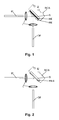
- Figure 1 shows an incoming fiber IF, an outgoing fiber OF, two lenses L and a reflecting element RE.
- the reflecting element RE is applied on a resistive element acting as a heating element HE applied on a substrate S.
- Incoming fiber IF, outgoing fiber OF, lenses L and reflecting element RE are adjusted such that light coming from the incoming fiber IF is output via the outgoing fiber OF, and, of course, vice-versa.
- the heating element HE is shown as part of an electric circuit further including a power source U and a remotely controllable switch RCS.
- the arrangement shown in figure 1 is suited for establishing an optical two-way data connection between the incoming fiber IF and the outgoing fiber OF.
- the power source U may be for example a remote power supply from the central station, a local power supply from the local subscriber's premises or a battery locally charged under normal operation. In case it is a mere power supply from the local subscriber's premises, abuse of the kind as mentioned above can not be hindered.
- the remotely controllable switch RCS is to be controlled from the central station, for example using control data sent to a "demarcation point" as mentioned above, in which such arrangement is contained.
- control data sent to a "demarcation point" as mentioned above, in which such arrangement is contained.
- the power source U is really a remote power supply from the central station, no such remotely controllable switch RCS is necessary within the remote line unit.
- Figure 2 shows the situation after the arrangement shown in figure 1 has been used to interrupt the optical two-way data connection.
- this element turned to a burned heating element HEB.
- Such burning has destroyed or removed the reflecting element RE of figure 1 depending of the kind of such reflecting element.
- a vapor deposited reflecting layer is likely to be destroyed; a reflecting foil glued on the heating element HE is likely to be removed.
- the remotely controllable switch RCS is now shown in figure 2 in a closed state.
- this switch RCS really is part of the remote line unit, then it is likely that it is no longer usable after having been activated. But the whole arrangement anyway is no longer workable and has to be replaced.
- optical fibers are complicated components with very specific optical properties. Such properties are very sensitive to improper surroundings like heat or aggressive air and thus their properties can easily be destroyed by electrically applied heat or by electrically activated chemicals.
Landscapes
- Engineering & Computer Science (AREA)
- Physics & Mathematics (AREA)
- Electromagnetism (AREA)
- Computer Networks & Wireless Communication (AREA)
- Signal Processing (AREA)
- Computer Security & Cryptography (AREA)
- Optical Communication System (AREA)
Abstract
Description
- The invention relates to a method for remote-controlled interrupting of an optical data line according to the preamble of claim 1, and to a line unit according to the preamble of claim 2.
- In all point-to-multi-point optical communication's systems, normally with a central station and a multiple of remote stations, devices at the multi-point side have to observe strict specifications, especially with respect to transmit times. If they do not observe such specifications, the whole communication's system will be severely affected.
- Devices foreseen for acting as such remote stations should be able to detect such malfunction and to switch off. But in case the device cannot detect such malfunction or a user injects light on purpose in a malicious way, the operator of such communication's system needs to have some means to disconnect that respective device from the network.
- For the purpose of monitoring the network part of such telecommunication's systems it is known to introduce so-called demarcation points as fiber network interfaces between the operator's network part and the user's network part or device. Patent application
EP 1 986 350 A1 (internal docket 801286) shows an example of such "demarcation point". For monitoring the line an optical MEMS switch (MEMS = Micro Electromechanical System) can be remotely activated to interrupt the line and terminate it with a mirror. This feature of course could be used also for cutting off the malfunctioning device. - The major drawback of such solution is the fact, that they involve moving elements. Since this function is rarely activated, if at all, the mechanically moving parts may be stuck in their position, just when they should be moved.
- It is the object of the invention to overcome this problem.
- This problem according to the invention is solved by a method according to the teaching of claim 1, and by a line unit according to the teaching of claim 2.
- It is easier and more reliable to irreversibly destroy whatever element in a remote device by means of electrically heating or electrically inducing a chemical process than to mechanically move it. In order to avoid a longer lasting blocking of the whole system an operator normally will accept that as a consequence the field service has to be engaged.
- Further embodiments of the invention are to be found in the subclaims and in the accompanying description.
- In the following the invention will be described with the aid of the accompanying drawing:
-
Figure 1 shows the use of a mirror with a reflecting element on a resistive layer in a line unit according to an exemplary embodiment of the invention. -
Figure 2 shows the situation offigure 1 after having applied the method according to the invention. -
Figure 1 shows an incoming fiber IF, an outgoing fiber OF, two lenses L and a reflecting element RE. The reflecting element RE is applied on a resistive element acting as a heating element HE applied on a substrate S. Incoming fiber IF, outgoing fiber OF, lenses L and reflecting element RE are adjusted such that light coming from the incoming fiber IF is output via the outgoing fiber OF, and, of course, vice-versa. The heating element HE is shown as part of an electric circuit further including a power source U and a remotely controllable switch RCS. - The arrangement shown in
figure 1 is suited for establishing an optical two-way data connection between the incoming fiber IF and the outgoing fiber OF. The two lenses L together with the reflecting element RE according to the teaching of claim such that the both fiber ends are mapped onto one another. - The power source U may be for example a remote power supply from the central station, a local power supply from the local subscriber's premises or a battery locally charged under normal operation. In case it is a mere power supply from the local subscriber's premises, abuse of the kind as mentioned above can not be hindered.
- The remotely controllable switch RCS is to be controlled from the central station, for example using control data sent to a "demarcation point" as mentioned above, in which such arrangement is contained. In case the power source U is really a remote power supply from the central station, no such remotely controllable switch RCS is necessary within the remote line unit.
-
Figure 2 shows the situation after the arrangement shown infigure 1 has been used to interrupt the optical two-way data connection. In applying power to the heating element HE offigure 1 this element turned to a burned heating element HEB. Such burning has destroyed or removed the reflecting element RE offigure 1 depending of the kind of such reflecting element. A vapor deposited reflecting layer is likely to be destroyed; a reflecting foil glued on the heating element HE is likely to be removed. - The remotely controllable switch RCS is now shown in
figure 2 in a closed state. When this switch RCS really is part of the remote line unit, then it is likely that it is no longer usable after having been activated. But the whole arrangement anyway is no longer workable and has to be replaced. - It is clear that here only the principle is shown. Instead of using a mirror one could also for example foresee to destroy the optical properties of an optical fiber. Optical fibers are complicated components with very specific optical properties. Such properties are very sensitive to improper surroundings like heat or aggressive air and thus their properties can easily be destroyed by electrically applied heat or by electrically activated chemicals.
- As it is very easy to destroy something, there are lots of possibilities to enable the invention. One needs only to take care that nothing else but the means for the optical data connection is destroyed (and of course that initiating the interrupting really can be done only on purpose).
Claims (4)
- Method for remote-controlled interrupting of an optical data line (IF, OF), characterized in, that means (HE) for irreversibly interrupting the data line (IF, OF) are triggered electrically (U, RCS).
- Line unit for establishing an optical data connection (IF, OF) between a device equipped with an optical data transmitter or data receiver and an optical data line, including means for interrupting the optical data connection by remote control (U, RCS), characterized in, that the means (HE, RE) are built such that the data connection (IF, OF) is irreversibly interrupted.
- Line unit according to claim 2, characterized in, that an optical reflecting layer (RE) is provided with an electrical heating (HE), the activation (U, RCS) of which destroys or removes the optical reflecting layer (RE).
- Line unit according to claim 2, characterized in, that an optical fiber is provided with an electrical heating, the activation of which destroys properties of the optical fiber.
Priority Applications (1)
| Application Number | Priority Date | Filing Date | Title |
|---|---|---|---|
| EP20090153207 EP2221996B1 (en) | 2009-02-19 | 2009-02-19 | Method for remote-controlled interrupting of an optical date line and line unit therefor |
Applications Claiming Priority (1)
| Application Number | Priority Date | Filing Date | Title |
|---|---|---|---|
| EP20090153207 EP2221996B1 (en) | 2009-02-19 | 2009-02-19 | Method for remote-controlled interrupting of an optical date line and line unit therefor |
Publications (2)
| Publication Number | Publication Date |
|---|---|
| EP2221996A1 true EP2221996A1 (en) | 2010-08-25 |
| EP2221996B1 EP2221996B1 (en) | 2013-01-09 |
Family
ID=40838950
Family Applications (1)
| Application Number | Title | Priority Date | Filing Date |
|---|---|---|---|
| EP20090153207 Not-in-force EP2221996B1 (en) | 2009-02-19 | 2009-02-19 | Method for remote-controlled interrupting of an optical date line and line unit therefor |
Country Status (1)
| Country | Link |
|---|---|
| EP (1) | EP2221996B1 (en) |
Cited By (1)
| Publication number | Priority date | Publication date | Assignee | Title |
|---|---|---|---|---|
| US9264150B2 (en) | 2012-03-28 | 2016-02-16 | Globalfoundries Inc. | Reactive metal optical security device and methods of fabrication and use |
Citations (2)
| Publication number | Priority date | Publication date | Assignee | Title |
|---|---|---|---|---|
| EP0499519A1 (en) * | 1991-02-12 | 1992-08-19 | Commissariat A L'energie Atomique | Optical cable with a destruction device for the optical fibres of the cable |
| JP2001308795A (en) | 2000-04-18 | 2001-11-02 | Oki Electric Ind Co Ltd | Optical fuse system |
-
2009
- 2009-02-19 EP EP20090153207 patent/EP2221996B1/en not_active Not-in-force
Patent Citations (2)
| Publication number | Priority date | Publication date | Assignee | Title |
|---|---|---|---|---|
| EP0499519A1 (en) * | 1991-02-12 | 1992-08-19 | Commissariat A L'energie Atomique | Optical cable with a destruction device for the optical fibres of the cable |
| JP2001308795A (en) | 2000-04-18 | 2001-11-02 | Oki Electric Ind Co Ltd | Optical fuse system |
Non-Patent Citations (1)
| Title |
|---|
| SHING-WA WONG; WEI-TAO SHAW; DAS, S.; KAZOVSKY, L.G.: "OPNO 1- 6: Enabling Security Countermeasure and Service Restoration in Passive Optical Networks", GLOBAL TELECOMMUNICATIONS CONFERENCE, 2006. GLOBECOM '06. IEEE, 27 November 2006 (2006-11-27), pages 1 - 5 |
Cited By (1)
| Publication number | Priority date | Publication date | Assignee | Title |
|---|---|---|---|---|
| US9264150B2 (en) | 2012-03-28 | 2016-02-16 | Globalfoundries Inc. | Reactive metal optical security device and methods of fabrication and use |
Also Published As
| Publication number | Publication date |
|---|---|
| EP2221996B1 (en) | 2013-01-09 |
Similar Documents
| Publication | Publication Date | Title |
|---|---|---|
| CN101912326B (en) | Control of automatic darkening filter | |
| RU2007129901A (en) | SYSTEM AND METHOD FOR MANAGING DEVICES CONNECTED TO A NETWORK BY AN OPEN FIELD BUS | |
| WO2006046247A3 (en) | Networked device control architecture | |
| WO2014093524A1 (en) | Security panel communication system | |
| EP3037902B1 (en) | Diagnostics and enhanced functionality for single-wire safety communication | |
| EP3442836A1 (en) | Gateway-based anti-theft security system and method | |
| EP2797283B1 (en) | Communication apparatus and method for communication | |
| WO2006075334A3 (en) | Iconic communication | |
| WO2007138393A3 (en) | Camera based control | |
| WO2008156019A1 (en) | Path setting method, access network switching method, access network switching device, mobile device, and proxy access network switching device | |
| WO2008156988A3 (en) | Docsis compatible pon architecture | |
| JP2008271553A5 (en) | ||
| SI2095519T1 (en) | A system for controlling electrical and/or electronic devices and equipments distributed in an environment, particularly a domestic environment | |
| ES2578737T3 (en) | Procedure and relay to communicate a parameter value from a source to be monitored | |
| EP2221996A1 (en) | Method for remote-controlled interrupting of an optical date line and line unit therefor | |
| EP3226486A1 (en) | Communication connection device and communication system | |
| FR2920142B1 (en) | DEVICE AND METHOD FOR CONTROLLING THE SUPPLY OF AT LEAST ONE MAINTENANCE ACTUATOR OF AN AIRCRAFT | |
| WO2008078819A1 (en) | Optical access network, remote device, optical communication method, and optical communication program | |
| CN102202055A (en) | Isolation gateway | |
| WO2009016684A1 (en) | Portable terminal device initialization method | |
| WO2005022953A1 (en) | Electric heating system | |
| EP3291121B1 (en) | Restore of headless electronic device | |
| KR100885809B1 (en) | Optical Ethernet Device with Remote Control Function | |
| EP2893495B1 (en) | Communication gateway and communication system including said communication gateway | |
| AU2014200963A1 (en) | Remote Control System |
Legal Events
| Date | Code | Title | Description |
|---|---|---|---|
| PUAI | Public reference made under article 153(3) epc to a published international application that has entered the european phase |
Free format text: ORIGINAL CODE: 0009012 |
|
| 17P | Request for examination filed |
Effective date: 20100118 |
|
| AK | Designated contracting states |
Kind code of ref document: A1 Designated state(s): AT BE BG CH CY CZ DE DK EE ES FI FR GB GR HR HU IE IS IT LI LT LU LV MC MK MT NL NO PL PT RO SE SI SK TR |
|
| AX | Request for extension of the european patent |
Extension state: AL BA RS |
|
| AKX | Designation fees paid |
Designated state(s): AT BE BG CH CY CZ DE DK EE ES FI FR GB GR HR HU IE IS IT LI LT LU LV MC MK MT NL NO PL PT RO SE SI SK TR |
|
| 17Q | First examination report despatched |
Effective date: 20120117 |
|
| RAP1 | Party data changed (applicant data changed or rights of an application transferred) |
Owner name: ALCATEL LUCENT |
|
| GRAJ | Information related to disapproval of communication of intention to grant by the applicant or resumption of examination proceedings by the epo deleted |
Free format text: ORIGINAL CODE: EPIDOSDIGR1 |
|
| GRAP | Despatch of communication of intention to grant a patent |
Free format text: ORIGINAL CODE: EPIDOSNIGR1 |
|
| GRAP | Despatch of communication of intention to grant a patent |
Free format text: ORIGINAL CODE: EPIDOSNIGR1 |
|
| GRAS | Grant fee paid |
Free format text: ORIGINAL CODE: EPIDOSNIGR3 |
|
| REG | Reference to a national code |
Ref country code: DE Ref legal event code: R079 Ref document number: 602009012595 Country of ref document: DE Free format text: PREVIOUS MAIN CLASS: H04B0010080000 Ipc: H04B0010070000 |
|
| GRAA | (expected) grant |
Free format text: ORIGINAL CODE: 0009210 |
|
| AK | Designated contracting states |
Kind code of ref document: B1 Designated state(s): AT BE BG CH CY CZ DE DK EE ES FI FR GB GR HR HU IE IS IT LI LT LU LV MC MK MT NL NO PL PT RO SE SI SK TR |
|
| REG | Reference to a national code |
Ref country code: GB Ref legal event code: FG4D |
|
| RIC1 | Information provided on ipc code assigned before grant |
Ipc: H04B 10/07 20130101AFI20121204BHEP |
|
| REG | Reference to a national code |
Ref country code: AT Ref legal event code: REF Ref document number: 593258 Country of ref document: AT Kind code of ref document: T Effective date: 20130115 Ref country code: CH Ref legal event code: EP |
|
| REG | Reference to a national code |
Ref country code: IE Ref legal event code: FG4D |
|
| REG | Reference to a national code |
Ref country code: DE Ref legal event code: R096 Ref document number: 602009012595 Country of ref document: DE Effective date: 20130314 |
|
| PG25 | Lapsed in a contracting state [announced via postgrant information from national office to epo] |
Ref country code: SI Free format text: LAPSE BECAUSE OF FAILURE TO SUBMIT A TRANSLATION OF THE DESCRIPTION OR TO PAY THE FEE WITHIN THE PRESCRIBED TIME-LIMIT Effective date: 20130109 |
|
| REG | Reference to a national code |
Ref country code: NL Ref legal event code: VDEP Effective date: 20130109 |
|
| REG | Reference to a national code |
Ref country code: AT Ref legal event code: MK05 Ref document number: 593258 Country of ref document: AT Kind code of ref document: T Effective date: 20130109 |
|
| REG | Reference to a national code |
Ref country code: LT Ref legal event code: MG4D |
|
| PG25 | Lapsed in a contracting state [announced via postgrant information from national office to epo] |
Ref country code: AT Free format text: LAPSE BECAUSE OF FAILURE TO SUBMIT A TRANSLATION OF THE DESCRIPTION OR TO PAY THE FEE WITHIN THE PRESCRIBED TIME-LIMIT Effective date: 20130109 Ref country code: BG Free format text: LAPSE BECAUSE OF FAILURE TO SUBMIT A TRANSLATION OF THE DESCRIPTION OR TO PAY THE FEE WITHIN THE PRESCRIBED TIME-LIMIT Effective date: 20130409 Ref country code: NO Free format text: LAPSE BECAUSE OF FAILURE TO SUBMIT A TRANSLATION OF THE DESCRIPTION OR TO PAY THE FEE WITHIN THE PRESCRIBED TIME-LIMIT Effective date: 20130409 Ref country code: ES Free format text: LAPSE BECAUSE OF FAILURE TO SUBMIT A TRANSLATION OF THE DESCRIPTION OR TO PAY THE FEE WITHIN THE PRESCRIBED TIME-LIMIT Effective date: 20130420 Ref country code: LT Free format text: LAPSE BECAUSE OF FAILURE TO SUBMIT A TRANSLATION OF THE DESCRIPTION OR TO PAY THE FEE WITHIN THE PRESCRIBED TIME-LIMIT Effective date: 20130109 Ref country code: BE Free format text: LAPSE BECAUSE OF FAILURE TO SUBMIT A TRANSLATION OF THE DESCRIPTION OR TO PAY THE FEE WITHIN THE PRESCRIBED TIME-LIMIT Effective date: 20130109 Ref country code: SE Free format text: LAPSE BECAUSE OF FAILURE TO SUBMIT A TRANSLATION OF THE DESCRIPTION OR TO PAY THE FEE WITHIN THE PRESCRIBED TIME-LIMIT Effective date: 20130109 Ref country code: IS Free format text: LAPSE BECAUSE OF FAILURE TO SUBMIT A TRANSLATION OF THE DESCRIPTION OR TO PAY THE FEE WITHIN THE PRESCRIBED TIME-LIMIT Effective date: 20130509 |
|
| PG25 | Lapsed in a contracting state [announced via postgrant information from national office to epo] |
Ref country code: PL Free format text: LAPSE BECAUSE OF FAILURE TO SUBMIT A TRANSLATION OF THE DESCRIPTION OR TO PAY THE FEE WITHIN THE PRESCRIBED TIME-LIMIT Effective date: 20130109 Ref country code: NL Free format text: LAPSE BECAUSE OF FAILURE TO SUBMIT A TRANSLATION OF THE DESCRIPTION OR TO PAY THE FEE WITHIN THE PRESCRIBED TIME-LIMIT Effective date: 20130109 Ref country code: GR Free format text: LAPSE BECAUSE OF FAILURE TO SUBMIT A TRANSLATION OF THE DESCRIPTION OR TO PAY THE FEE WITHIN THE PRESCRIBED TIME-LIMIT Effective date: 20130410 Ref country code: LV Free format text: LAPSE BECAUSE OF FAILURE TO SUBMIT A TRANSLATION OF THE DESCRIPTION OR TO PAY THE FEE WITHIN THE PRESCRIBED TIME-LIMIT Effective date: 20130109 Ref country code: PT Free format text: LAPSE BECAUSE OF FAILURE TO SUBMIT A TRANSLATION OF THE DESCRIPTION OR TO PAY THE FEE WITHIN THE PRESCRIBED TIME-LIMIT Effective date: 20130509 Ref country code: FI Free format text: LAPSE BECAUSE OF FAILURE TO SUBMIT A TRANSLATION OF THE DESCRIPTION OR TO PAY THE FEE WITHIN THE PRESCRIBED TIME-LIMIT Effective date: 20130109 |
|
| PG25 | Lapsed in a contracting state [announced via postgrant information from national office to epo] |
Ref country code: HR Free format text: LAPSE BECAUSE OF FAILURE TO SUBMIT A TRANSLATION OF THE DESCRIPTION OR TO PAY THE FEE WITHIN THE PRESCRIBED TIME-LIMIT Effective date: 20130109 Ref country code: MC Free format text: LAPSE BECAUSE OF NON-PAYMENT OF DUE FEES Effective date: 20130228 |
|
| REG | Reference to a national code |
Ref country code: CH Ref legal event code: PL |
|
| PG25 | Lapsed in a contracting state [announced via postgrant information from national office to epo] |
Ref country code: CZ Free format text: LAPSE BECAUSE OF FAILURE TO SUBMIT A TRANSLATION OF THE DESCRIPTION OR TO PAY THE FEE WITHIN THE PRESCRIBED TIME-LIMIT Effective date: 20130109 Ref country code: EE Free format text: LAPSE BECAUSE OF FAILURE TO SUBMIT A TRANSLATION OF THE DESCRIPTION OR TO PAY THE FEE WITHIN THE PRESCRIBED TIME-LIMIT Effective date: 20130109 Ref country code: LI Free format text: LAPSE BECAUSE OF NON-PAYMENT OF DUE FEES Effective date: 20130228 Ref country code: RO Free format text: LAPSE BECAUSE OF FAILURE TO SUBMIT A TRANSLATION OF THE DESCRIPTION OR TO PAY THE FEE WITHIN THE PRESCRIBED TIME-LIMIT Effective date: 20130109 Ref country code: SK Free format text: LAPSE BECAUSE OF FAILURE TO SUBMIT A TRANSLATION OF THE DESCRIPTION OR TO PAY THE FEE WITHIN THE PRESCRIBED TIME-LIMIT Effective date: 20130109 Ref country code: DK Free format text: LAPSE BECAUSE OF FAILURE TO SUBMIT A TRANSLATION OF THE DESCRIPTION OR TO PAY THE FEE WITHIN THE PRESCRIBED TIME-LIMIT Effective date: 20130109 Ref country code: CH Free format text: LAPSE BECAUSE OF NON-PAYMENT OF DUE FEES Effective date: 20130228 |
|
| PLBE | No opposition filed within time limit |
Free format text: ORIGINAL CODE: 0009261 |
|
| STAA | Information on the status of an ep patent application or granted ep patent |
Free format text: STATUS: NO OPPOSITION FILED WITHIN TIME LIMIT |
|
| REG | Reference to a national code |
Ref country code: FR Ref legal event code: GC Effective date: 20131018 |
|
| PG25 | Lapsed in a contracting state [announced via postgrant information from national office to epo] |
Ref country code: CY Free format text: LAPSE BECAUSE OF FAILURE TO SUBMIT A TRANSLATION OF THE DESCRIPTION OR TO PAY THE FEE WITHIN THE PRESCRIBED TIME-LIMIT Effective date: 20130109 |
|
| REG | Reference to a national code |
Ref country code: IE Ref legal event code: MM4A |
|
| 26N | No opposition filed |
Effective date: 20131010 |
|
| PG25 | Lapsed in a contracting state [announced via postgrant information from national office to epo] |
Ref country code: IT Free format text: LAPSE BECAUSE OF FAILURE TO SUBMIT A TRANSLATION OF THE DESCRIPTION OR TO PAY THE FEE WITHIN THE PRESCRIBED TIME-LIMIT Effective date: 20130109 |
|
| REG | Reference to a national code |
Ref country code: DE Ref legal event code: R097 Ref document number: 602009012595 Country of ref document: DE Effective date: 20131010 |
|
| PG25 | Lapsed in a contracting state [announced via postgrant information from national office to epo] |
Ref country code: IE Free format text: LAPSE BECAUSE OF NON-PAYMENT OF DUE FEES Effective date: 20130219 |
|
| PG25 | Lapsed in a contracting state [announced via postgrant information from national office to epo] |
Ref country code: MT Free format text: LAPSE BECAUSE OF FAILURE TO SUBMIT A TRANSLATION OF THE DESCRIPTION OR TO PAY THE FEE WITHIN THE PRESCRIBED TIME-LIMIT Effective date: 20130109 |
|
| REG | Reference to a national code |
Ref country code: FR Ref legal event code: RG Effective date: 20141016 |
|
| REG | Reference to a national code |
Ref country code: FR Ref legal event code: PLFP Year of fee payment: 7 |
|
| PG25 | Lapsed in a contracting state [announced via postgrant information from national office to epo] |
Ref country code: TR Free format text: LAPSE BECAUSE OF FAILURE TO SUBMIT A TRANSLATION OF THE DESCRIPTION OR TO PAY THE FEE WITHIN THE PRESCRIBED TIME-LIMIT Effective date: 20130109 |
|
| PG25 | Lapsed in a contracting state [announced via postgrant information from national office to epo] |
Ref country code: LU Free format text: LAPSE BECAUSE OF NON-PAYMENT OF DUE FEES Effective date: 20130219 Ref country code: MK Free format text: LAPSE BECAUSE OF FAILURE TO SUBMIT A TRANSLATION OF THE DESCRIPTION OR TO PAY THE FEE WITHIN THE PRESCRIBED TIME-LIMIT Effective date: 20130109 Ref country code: HU Free format text: LAPSE BECAUSE OF FAILURE TO SUBMIT A TRANSLATION OF THE DESCRIPTION OR TO PAY THE FEE WITHIN THE PRESCRIBED TIME-LIMIT; INVALID AB INITIO Effective date: 20090219 |
|
| REG | Reference to a national code |
Ref country code: FR Ref legal event code: PLFP Year of fee payment: 8 |
|
| REG | Reference to a national code |
Ref country code: FR Ref legal event code: PLFP Year of fee payment: 9 |
|
| REG | Reference to a national code |
Ref country code: FR Ref legal event code: PLFP Year of fee payment: 10 |
|
| PGFP | Annual fee paid to national office [announced via postgrant information from national office to epo] |
Ref country code: FR Payment date: 20190111 Year of fee payment: 11 Ref country code: GB Payment date: 20190213 Year of fee payment: 11 Ref country code: DE Payment date: 20190205 Year of fee payment: 11 |
|
| REG | Reference to a national code |
Ref country code: DE Ref legal event code: R119 Ref document number: 602009012595 Country of ref document: DE |
|
| GBPC | Gb: european patent ceased through non-payment of renewal fee |
Effective date: 20200219 |
|
| PG25 | Lapsed in a contracting state [announced via postgrant information from national office to epo] |
Ref country code: GB Free format text: LAPSE BECAUSE OF NON-PAYMENT OF DUE FEES Effective date: 20200219 Ref country code: DE Free format text: LAPSE BECAUSE OF NON-PAYMENT OF DUE FEES Effective date: 20200901 Ref country code: FR Free format text: LAPSE BECAUSE OF NON-PAYMENT OF DUE FEES Effective date: 20200229 |