EP2221946A2 - Stator bar with end arm aligned with stator core slot - Google Patents
Stator bar with end arm aligned with stator core slot Download PDFInfo
- Publication number
- EP2221946A2 EP2221946A2 EP10152877A EP10152877A EP2221946A2 EP 2221946 A2 EP2221946 A2 EP 2221946A2 EP 10152877 A EP10152877 A EP 10152877A EP 10152877 A EP10152877 A EP 10152877A EP 2221946 A2 EP2221946 A2 EP 2221946A2
- Authority
- EP
- European Patent Office
- Prior art keywords
- stator
- stator bar
- slot
- bar
- end arm
- Prior art date
- Legal status (The legal status is an assumption and is not a legal conclusion. Google has not performed a legal analysis and makes no representation as to the accuracy of the status listed.)
- Withdrawn
Links
- 239000011343 solid material Substances 0.000 claims description 3
- 238000004804 winding Methods 0.000 description 4
- 239000002184 metal Substances 0.000 description 3
- 229910052751 metal Inorganic materials 0.000 description 3
- RYGMFSIKBFXOCR-UHFFFAOYSA-N Copper Chemical compound [Cu] RYGMFSIKBFXOCR-UHFFFAOYSA-N 0.000 description 2
- 229910052802 copper Inorganic materials 0.000 description 2
- 239000010949 copper Substances 0.000 description 2
- 238000010276 construction Methods 0.000 description 1
- 239000011152 fibreglass Substances 0.000 description 1
- 230000002452 interceptive effect Effects 0.000 description 1
- 238000012423 maintenance Methods 0.000 description 1
- 239000000463 material Substances 0.000 description 1
- 238000005259 measurement Methods 0.000 description 1
- 150000002739 metals Chemical class 0.000 description 1
- 238000000034 method Methods 0.000 description 1
- 239000010445 mica Substances 0.000 description 1
- 229910052618 mica group Inorganic materials 0.000 description 1
- 238000012986 modification Methods 0.000 description 1
- 230000004048 modification Effects 0.000 description 1
- 239000003607 modifier Substances 0.000 description 1
- 238000004080 punching Methods 0.000 description 1
- 238000012360 testing method Methods 0.000 description 1
Images




Classifications
-
- H—ELECTRICITY
- H02—GENERATION; CONVERSION OR DISTRIBUTION OF ELECTRIC POWER
- H02K—DYNAMO-ELECTRIC MACHINES
- H02K3/00—Details of windings
- H02K3/04—Windings characterised by the conductor shape, form or construction, e.g. with bar conductors
- H02K3/12—Windings characterised by the conductor shape, form or construction, e.g. with bar conductors arranged in slots
Definitions
- the invention relates generally to dynamoelectric devices such as generators and large motors. More particularly, the invention relates to a dynamoelectric device having a stator bar with an end arm involute portion substantially aligned with a stator core slot and a related method.
- Rotor 102 may include any now known or later developed rotor structure.
- Stator 100 includes a stator core 110 including a plurality of layered punchings 112.
- stator core 110 includes a number of circumferentially arranged slots 114 that extend in a radial direction relative to an axis Z of stator 100.
- Each slot 114 has a pair of stator bars 120 positioned radially therein.
- Stator bars 120 are conductive, metal bars that are covered with a dielectric, and are coupled together so as to create an electrical winding circuit.
- Each stator bar 120 includes a linear portion 122 for positioning in a slot 114 of stator core 110 and an end arm portion 130 that extends outwardly past stator core 110 and slots 114 to form an endwinding region 128.
- each stator bar 120 has an elongated cross-section, e.g., substantially rectangular, or oblong, etc.
- each end arm portion 130 includes an involute-on-cone bend 132 relative to linear portion 122.
- the involute portion is typically represented by an equivalent radius. That is, end arm portion 130 extends outwardly so as to form a cone shape (actually frusto-conical shape) when juxtaposed with other end arm portions, and extends circumferentially in one direction so as to form an involute portion relative to linear portion 122.
- Bend 132 is provided such that an end 140 of a stator bar 120 is positioned, for example, approximately 60 to 80 degrees away from slot 114 ( FIG. 1 ), which permits connection of stator bar 120 ( FIG. 1 ) to a radially adjacent stator bar 142 so as to continue the electrical winding circuit.
- each stator bar 120 ( FIG. 1 ) is positioned relative to adjacent stator bar(s) by radially moving it into a slot 114 ( FIG. 1 ).
- sides of end arm portions 130 interfere with adjacent end arm portions 130 in involute-on-cone bend 132 during assembly.
- assemblers must flex and stress end arm portions 130, which some times leads to dielectric test failures that require replacement of the failed stator bar.
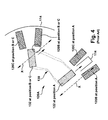
- FIGS. 3-5 illustrate the problem at four locations A-D along an end arm portion 130 of a stator bar 120A to be positioned relative to an end arm portion 130 of an already positioned stator bar 120B (120B and 120C in FIG. 4 ).
- FIG. 4 shows how a linear portion 122 of a stator bar 120 ( FIG. 1 ) is positioned to slide into slot 114, while involute-on-cone bend 132 at positions B or C, as shown in FIG. 3 , are positioned so as to be perpendicular to a cone shape 144 (shown as line in FIG. 4 ) formed by end arm portions 130.
- FIG. 5 shows a schematic cross-sectional view of a pair of end arms 120A, 120B at all locations A-D as denoted in FIG. 3 .
- the initial position of stator bar 120A to be positioned is shown in phantom, while the final position is shown in solid line.
- position A near linear portion 122, as in FIG.
- stator bar 120A to be positioned relative to an already positioned stator bar 120B can be easily positioned into slot 114 (not shown) without interfering with stator bar 120B.
- stator bar 120A interferes with already positioned stator bar 120B (in circles) as the stator bar moves along radial direction of travel X.
- no interference may be present or is less of a concern due to increased allowable flex.
- a first aspect of the disclosure provides a stator bar for a stator of a dynamoelectric device, the stator bar comprising: a linear portion for positioning in a slot of a stator core, the slot extending in a radial direction relative to an axis of the stator; and an end arm portion having an involute-on-cone bend relative to the linear portion and an elongated cross-section that is substantially aligned with the radial direction of the slot.
- a second aspect of the disclosure provides a dynamoelectric device comprising: a rotor; a stator including a stator bar for a stator of the dynamoelectric device, the stator bar including: a linear portion for positioning in a slot of a stator core, the slot extending in a radial direction relative to an axis of the stator; and an end arm portion having an involute-on-cone bend relative to the linear portion and an elongated cross-section that is substantially aligned with the radial direction of the slot.
- FIGS. 6-8 a stator bar 220 according to embodiments of the invention is illustrated. Although embodiments of the invention are illustrated relative to a dynamoelectric device in the form of a generator, it is understood that the teachings are equally applicable to other dynamoelectric devices such as large motors.
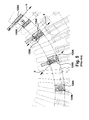
- FIGS. 6 and 8 illustrate stator bar 220 at locations A-D along an end arm portion 230 of a stator bar 220A to be positioned relative to an end arm portion 230 of an already positioned stator bar 220B (220B and 220C in FIG. 7).
- FIG. 7 shows cross-sectional views of end arm portion 230 at the stator slot position A and at a location along the involute portion of end arm portion 230.
- stator bar 220 may include a solid material such as copper with an insulative layer of fiberglass and mica adhered to the copper, and may have a radial height (H) ( FIG. 7 ) in the range of 1.5 to 4.5 inches with an aspect ratio in the range of 1 to 6.
- H radial height
- stator bar 220 includes a linear portion 222 for positioning in slot 114 of stator core 110 ( FIG. 1 ).
- slot 114 extends in a radial direction relative to an axis Z of stator 100 ( FIG. 1 ).
- an end arm portion 230 includes an involute-on-cone bend 232 relative to linear portion 222 and an elongated cross-section that is substantially aligned with the radial direction of slot 114. That is, involute-on-cone bend 232 is positioned so as not to be perpendicular to a cone shape 244 (shown as line in FIG.
- each stator bar 220 is positioned relative to adjacent stator bar(s) 220B, 220C by radially moving it into a slot 114.
- sides of end arm portions 230 interference with adjacent end arm portions 230 in involute-on-cone bend 232 is minimized because the bend is substantially aligned (i.e., aligned or offset so as to be substantially parallel) with the radial direction of travel upon which it must move.
- stator bars 220B, 220C are similarly angled, the amount of flex and stress that assemblers must exert on end arm portions 230 may be drastically reduced or eliminated.
- the alignment allows for a reduced spacing between adjacent stator bars 220, for example, to approximately 0.125 inches.
- Bend 232 may be provided such that an end 240 of stator bar 220 is positioned, for example, approximately 60 to 80 degrees away from slot 114, which permits connection of stator bar 220 to a radially adjacent stator bar so as to continue the electrical winding circuit.
- FIG. 8 shows a schematic cross-sectional view of a pair of end arms 220A, 220B at all locations A-D as denoted in FIG. 6 .
- the initial position of stator bar 220A to be positioned is shown in phantom, while the final position is shown in solid line.
- stator bar 220A can be easily positioned with little or no interference as stator bar 220A moves along radial direction of travel X. This is the case regardless of whether positioning of stator bar 220A into slot 114 (not shown) is observed at position A, along bend 232 at positions B or C, or at an end 240 at position D.
- stator bar 220 can move into or out of the stator core 110 ( FIG. 1 ) by moving linear portion 222 into or out of slot 114, respectively, along a radial direction of travel, and end arm portion 230 will move parallel to the direction of travel X so as to be positioned between adjacent end arm portions.
- first,” “second,” and the like, herein do not denote any order, quantity, or importance, but rather are used to distinguish one element from another, and the terms “a” and “an” herein do not denote a limitation of quantity, but rather denote the presence of at least one of the referenced item.
- the modifier “about” used in connection with a quantity is inclusive of the stated value and has the meaning dictated by the context, (e.g., includes the degree of error associated with measurement of the particular quantity).
- suffix "(s)” as used herein is intended to include both the singular and the plural of the term that it modifies, thereby including one or more of that term (e.g., the metal(s) includes one or more metals).
- Ranges disclosed herein are inclusive and independently combinable (e.g., ranges of "up to about 25 wt%, or, more specifically, about 5 wt% to about 20 wt %", is inclusive of the endpoints and all intermediate values of the ranges of "about 5 wt% to about 25 wt%,” etc).
Landscapes
- Engineering & Computer Science (AREA)
- Power Engineering (AREA)
- Manufacture Of Motors, Generators (AREA)
- Windings For Motors And Generators (AREA)
Abstract
Dynamoelectric device and stator bar (220) therefor, where the stator bar (220) includes a linear portion (222) for positioning in a slot (114) of a stator core, the slot (114) extending in a radial direction relative to an axis of the stator, and an end arm portion (230) having an involute-on-cone bend (232) relative to the linear portion (222) and an elongated cross-section that is substantially aligned with the radial direction of the slot (114).
Description
- The invention relates generally to dynamoelectric devices such as generators and large motors. More particularly, the invention relates to a dynamoelectric device having a stator bar with an end arm involute portion substantially aligned with a stator core slot and a related method.
- Referring to
FIG. 1 , portions of astator 100 and arotor 102 of a conventional dynamoelectric device in the form of agenerator 104 are illustrated.Rotor 102 may include any now known or later developed rotor structure.Stator 100 includes astator core 110 including a plurality oflayered punchings 112. As known in the art,stator core 110 includes a number of circumferentially arrangedslots 114 that extend in a radial direction relative to an axis Z ofstator 100. Eachslot 114 has a pair ofstator bars 120 positioned radially therein.Stator bars 120 are conductive, metal bars that are covered with a dielectric, and are coupled together so as to create an electrical winding circuit. Eachstator bar 120 includes alinear portion 122 for positioning in aslot 114 ofstator core 110 and anend arm portion 130 that extends outwardlypast stator core 110 andslots 114 to form anendwinding region 128. - Referring to
FIGS. 2-3 , enlarged perspective views ofend winding region 128 of generator 104 (FIG. 1 ) are illustrated. As shown, each stator bar 120 (FIG. 1 ) has an elongated cross-section, e.g., substantially rectangular, or oblong, etc. Further, eachend arm portion 130 includes an involute-on-cone bend 132 relative tolinear portion 122. The involute portion is typically represented by an equivalent radius. That is,end arm portion 130 extends outwardly so as to form a cone shape (actually frusto-conical shape) when juxtaposed with other end arm portions, and extends circumferentially in one direction so as to form an involute portion relative tolinear portion 122.Bend 132 is provided such that anend 140 of astator bar 120 is positioned, for example, approximately 60 to 80 degrees away from slot 114 (FIG. 1 ), which permits connection of stator bar 120 (FIG. 1 ) to a radiallyadjacent stator bar 142 so as to continue the electrical winding circuit. - During assembly, each stator bar 120 (
FIG. 1 ) is positioned relative to adjacent stator bar(s) by radially moving it into a slot 114 (FIG. 1 ). However, where previous stator bars have been positioned, sides ofend arm portions 130 interfere with adjacentend arm portions 130 in involute-on-cone bend 132 during assembly. In order to address this issue, assemblers must flex and stressend arm portions 130, which some times leads to dielectric test failures that require replacement of the failed stator bar. -
FIGS. 3-5 illustrate the problem at four locations A-D along anend arm portion 130 of astator bar 120A to be positioned relative to anend arm portion 130 of an already positionedstator bar 120B (120B and 120C inFIG. 4 ). In particular,FIG. 4 shows how alinear portion 122 of a stator bar 120 (FIG. 1 ) is positioned to slide intoslot 114, while involute-on-cone bend 132 at positions B or C, as shown inFIG. 3 , are positioned so as to be perpendicular to a cone shape 144 (shown as line inFIG. 4 ) formed byend arm portions 130. Asstator bar 120A moves along radial direction of travel X atlinear portion 122 at position A so as to slide intoslot 114, involute-on-cone bend 132 at position B or C interferes withadjacent stator bar 120B (in circle).FIG. 5 shows a schematic cross-sectional view of a pair ofend arms FIG. 3 . InFIG. 5 , the initial position ofstator bar 120A to be positioned is shown in phantom, while the final position is shown in solid line. At position A, nearlinear portion 122, as inFIG. 4 ,stator bar 120A to be positioned relative to an already positionedstator bar 120B can be easily positioned into slot 114 (not shown) without interfering withstator bar 120B. At positions B and C, however,stator bar 120A interferes with already positionedstator bar 120B (in circles) as the stator bar moves along radial direction of travel X. At position D, no interference may be present or is less of a concern due to increased allowable flex. - A first aspect of the disclosure provides a stator bar for a stator of a dynamoelectric device, the stator bar comprising: a linear portion for positioning in a slot of a stator core, the slot extending in a radial direction relative to an axis of the stator; and an end arm portion having an involute-on-cone bend relative to the linear portion and an elongated cross-section that is substantially aligned with the radial direction of the slot.
- A second aspect of the disclosure provides a dynamoelectric device comprising: a rotor; a stator including a stator bar for a stator of the dynamoelectric device, the stator bar including: a linear portion for positioning in a slot of a stator core, the slot extending in a radial direction relative to an axis of the stator; and an end arm portion having an involute-on-cone bend relative to the linear portion and an elongated cross-section that is substantially aligned with the radial direction of the slot.
- There follows a detailed description of embodiments of the invention by way of example only with reference to the accompanying drawings, in which:
-
FIG. 1 shows a partial cross-sectional view of a conventional generator near an end thereof; -
FIG. 2 shows a perspective view of an end arm portion of the conventional generator ofFIG. 1 ; -
FIG. 3 shows an enlarged perspective view of an involute-on-cone portion of the end arm portion ofFIG. 2 ; -
FIG. 4 shows cross-sectional views of the end arm portion at the stator slot position and at location(s) along the involute portion of the end arm for a conventional generator; -
FIG. 5 shows a schematic cross-sectional view of a pair of end arms at locations A-D as denoted inFIG. 3 ; -
FIG. 6 shows an enlarged perspective view of an involute-on-cone portion of the end arm portion according to embodiments of the invention; -
FIG. 7 shows cross-sectional views of the end arm portion at the stator slot position and at a location along the involute portion of the end arm portion according to embodiments of the invention; and -
FIG. 8 shows a schematic cross-sectional view of a pair of end arm portions at locations A-D as denoted inFIG. 6 . - Referring to
FIGS. 6-8 , astator bar 220 according to embodiments of the invention is illustrated. Although embodiments of the invention are illustrated relative to a dynamoelectric device in the form of a generator, it is understood that the teachings are equally applicable to other dynamoelectric devices such as large motors.FIGS. 6 and8 illustrate stator bar 220 at locations A-D along anend arm portion 230 of astator bar 220A to be positioned relative to anend arm portion 230 of an already positionedstator bar 220B (220B and 220C inFIG. 7). FIG. 7 shows cross-sectional views ofend arm portion 230 at the stator slot position A and at a location along the involute portion ofend arm portion 230. In one embodiment,stator bar 220 may include a solid material such as copper with an insulative layer of fiberglass and mica adhered to the copper, and may have a radial height (H) (FIG. 7 ) in the range of 1.5 to 4.5 inches with an aspect ratio in the range of 1 to 6. - In one embodiment,
stator bar 220 includes alinear portion 222 for positioning inslot 114 of stator core 110 (FIG. 1 ). As noted herein, and as shown inFIG. 7 ,slot 114 extends in a radial direction relative to an axis Z of stator 100 (FIG. 1 ). As shown best inFIGS. 6 and7 , in contrast to conventional stator bars, anend arm portion 230 includes an involute-on-cone bend 232 relative tolinear portion 222 and an elongated cross-section that is substantially aligned with the radial direction ofslot 114. That is, involute-on-cone bend 232 is positioned so as not to be perpendicular to a cone shape 244 (shown as line inFIG. 7 ) formed byend arm portions 230, but parallel tolinear portion 222. Consequently, as shown best inFIG. 7 , during assembly, eachstator bar 220 is positioned relative to adjacent stator bar(s) 220B, 220C by radially moving it into aslot 114. Where previous stator bars have been positioned, sides ofend arm portions 230 interference with adjacentend arm portions 230 in involute-on-cone bend 232 is minimized because the bend is substantially aligned (i.e., aligned or offset so as to be substantially parallel) with the radial direction of travel upon which it must move. Sinceadjacent stator bars end arm portions 230 may be drastically reduced or eliminated. In addition, in one embodiment, the alignment allows for a reduced spacing betweenadjacent stator bars 220, for example, to approximately 0.125 inches.Bend 232 may be provided such that anend 240 ofstator bar 220 is positioned, for example, approximately 60 to 80 degrees away fromslot 114, which permits connection ofstator bar 220 to a radially adjacent stator bar so as to continue the electrical winding circuit. -
FIG. 8 shows a schematic cross-sectional view of a pair ofend arms FIG. 6 . InFIG. 8 , the initial position ofstator bar 220A to be positioned is shown in phantom, while the final position is shown in solid line. In contrast to conventional stator bar 120 (FIGS. 1-5 ), at all positions A-D,stator bar 220A can be easily positioned with little or no interference asstator bar 220A moves along radial direction of travel X. This is the case regardless of whether positioning ofstator bar 220A into slot 114 (not shown) is observed at position A, alongbend 232 at positions B or C, or at anend 240 at position D. Furthermore, this is the case regardless of whetherstator bar 220 is being initially placed during construction of generator 104 (FIG. 1 ) orstator bar 220 is being removed for maintenance or replacement. That is,stator bar 220 can move into or out of the stator core 110 (FIG. 1 ) by movinglinear portion 222 into or out ofslot 114, respectively, along a radial direction of travel, andend arm portion 230 will move parallel to the direction of travel X so as to be positioned between adjacent end arm portions. - The terms "first," "second," and the like, herein do not denote any order, quantity, or importance, but rather are used to distinguish one element from another, and the terms "a" and "an" herein do not denote a limitation of quantity, but rather denote the presence of at least one of the referenced item. The modifier "about" used in connection with a quantity is inclusive of the stated value and has the meaning dictated by the context, (e.g., includes the degree of error associated with measurement of the particular quantity). The suffix "(s)" as used herein is intended to include both the singular and the plural of the term that it modifies, thereby including one or more of that term (e.g., the metal(s) includes one or more metals). Ranges disclosed herein are inclusive and independently combinable (e.g., ranges of "up to about 25 wt%, or, more specifically, about 5 wt% to about 20 wt %", is inclusive of the endpoints and all intermediate values of the ranges of "about 5 wt% to about 25 wt%," etc).
- While various embodiments are described herein, it will be appreciated from the specification that various combinations of elements, variations or improvements therein may be made by those skilled in the art, and are within the scope of the invention. In addition, many modifications may be made to adapt a particular situation or material to the teachings of the invention without departing from essential scope thereof. Therefore, it is intended that the invention not be limited to the particular embodiment disclosed as the best mode contemplated for carrying out this invention, but that the invention will include all embodiments falling within the scope of the appended claims.
Claims (13)
- A stator bar (220) for a stator of a dynamoelectric device, the stator bar (220) comprising:a linear portion for positioning in a slot (114) of a stator core, the slot (114) extending in a radial direction relative to an axis of the stator; andan end arm portion (230) having an involute-on-cone bend (232) relative to the linear portion and an elongated cross-section that is substantially aligned with the radial direction of the slot (114).
- The stator bar of claim 1, wherein the elongated cross-section is substantially rectangular.
- The stator bar of claim 1 or 2, wherein the stator bar (220) includes a solid material.
- The stator bar of claim 3, wherein the elongated cross-section has a radial height in a range of approximately 1.5 to 4.5 inches.
- The stator bar of claim 4, wherein the elongated cross-section has an aspect ratio of approximately 1 to 6.
- The stator bar of any of the preceding claims, wherein the involute-on-cone bend (232) is angled relative to the linear portion in a range of approximately 60 to 80 degrees.
- A dynamoelectric device comprising:a rotor;a stator including a stator bar (220) for a stator of the dynamoelectric device, the stator bar (220) including:a linear portion for positioning in a slot (114) of a stator core, the slot (114) extending in a radial direction relative to an axis of the stator; andan end arm portion (230) having an involute-on-cone bend (232) relative to the linear portion and an elongated cross-section that is substantially aligned with the radial direction of the slot (114).
- The dynamoelectric device of claim 7, wherein the elongated cross-section is substantially rectangular.
- The dynamoelectric device of claim 7 or 8, wherein the stator bar (220) includes a solid material.
- The dynamoelectric device of any of claims 7 to 9, wherein the elongated cross-section has a radial height in a range of approximately 1.5 to 4.5 inches.
- The dynamoelectric device of claim 10, wherein the elongated cross-section has an aspect ratio of approximately 1 to 6.
- The dynamoelectric device of any of claims 7 to 11, wherein the involute-on-cone bend (232) is angled relative to the linear portion in a range of approximately 60 to 80 degrees.
- The dynamoelectric device of any of claims 7 to 12, further comprising a plurality of adjacent stator bars (220), wherein a spacing between adjacent stator bars (120, 220) is approximately 0.125 inches.
Applications Claiming Priority (1)
| Application Number | Priority Date | Filing Date | Title |
|---|---|---|---|
| US12/388,687 US7928625B2 (en) | 2009-02-19 | 2009-02-19 | Stator bar with end arm involute-on-cone bend substantially aligned with stator core slot |
Publications (1)
| Publication Number | Publication Date |
|---|---|
| EP2221946A2 true EP2221946A2 (en) | 2010-08-25 |
Family
ID=41682712
Family Applications (1)
| Application Number | Title | Priority Date | Filing Date |
|---|---|---|---|
| EP10152877A Withdrawn EP2221946A2 (en) | 2009-02-19 | 2010-02-08 | Stator bar with end arm aligned with stator core slot |
Country Status (4)
| Country | Link |
|---|---|
| US (2) | US7928625B2 (en) |
| EP (1) | EP2221946A2 (en) |
| JP (1) | JP2010193708A (en) |
| KR (1) | KR20100094958A (en) |
Cited By (1)
| Publication number | Priority date | Publication date | Assignee | Title |
|---|---|---|---|---|
| EP2784910A1 (en) * | 2013-03-26 | 2014-10-01 | Siemens Aktiengesellschaft | An insulator assembly and a method of making the insulator assembly |
Families Citing this family (6)
| Publication number | Priority date | Publication date | Assignee | Title |
|---|---|---|---|---|
| JP5389109B2 (en) * | 2011-07-21 | 2014-01-15 | 本田技研工業株式会社 | Rotating electric machine stator |
| JP5395130B2 (en) * | 2011-07-21 | 2014-01-22 | 本田技研工業株式会社 | Manufacturing method of stator of rotating electric machine |
| CN102790483B (en) * | 2012-08-30 | 2014-07-09 | 哈尔滨电机厂有限责任公司 | Three-dimensional parametric modeling and solid forming manufacture method of steam turbine generator stator bar |
| CN108880141B (en) * | 2018-09-05 | 2023-12-15 | 中国长江动力集团有限公司 | Verification device for simulating stator tool and stator bar |
| CN115224885A (en) * | 2022-07-21 | 2022-10-21 | 山东齐鲁电机制造有限公司 | Generator stator bar end bending equipment |
| CN118630992B (en) * | 2024-06-07 | 2026-01-23 | 中国长江电力股份有限公司 | Ejector device and ejector method for stator bar of hydroelectric generating set |
Family Cites Families (6)
| Publication number | Priority date | Publication date | Assignee | Title |
|---|---|---|---|---|
| US1238280A (en) * | 1913-08-02 | 1917-08-28 | Westinghouse Electric & Mfg Co | Coil-support. |
| US2602829A (en) * | 1950-09-02 | 1952-07-08 | Westinghouse Electric Corp | Inorganic rope impregnated with resin and coils blocked therewith |
| US3348085A (en) * | 1965-07-20 | 1967-10-17 | Gen Electric | Spring tightened generator end turn support construction |
| JPS6051344B2 (en) * | 1977-07-25 | 1985-11-13 | 株式会社日立製作所 | Ventilation cooling system for vertical turbine generator |
| US4278905A (en) * | 1977-12-27 | 1981-07-14 | Electric Power Research Institute | Apparatus for supporting a stator winding in a superconductive generator |
| US7216796B2 (en) * | 2004-05-10 | 2007-05-15 | General Electric, Company | Crevice corrosion-resistant liquid-cooled armature bar clip-to-strand connection and related method |
-
2009
- 2009-02-19 US US12/388,687 patent/US7928625B2/en not_active Expired - Fee Related
-
2010
- 2010-02-08 EP EP10152877A patent/EP2221946A2/en not_active Withdrawn
- 2010-02-16 JP JP2010030786A patent/JP2010193708A/en not_active Withdrawn
- 2010-02-18 KR KR1020100014652A patent/KR20100094958A/en not_active Withdrawn
-
2011
- 2011-02-28 US US13/036,621 patent/US8134274B2/en not_active Expired - Fee Related
Non-Patent Citations (1)
| Title |
|---|
| None |
Cited By (1)
| Publication number | Priority date | Publication date | Assignee | Title |
|---|---|---|---|---|
| EP2784910A1 (en) * | 2013-03-26 | 2014-10-01 | Siemens Aktiengesellschaft | An insulator assembly and a method of making the insulator assembly |
Also Published As
| Publication number | Publication date |
|---|---|
| US7928625B2 (en) | 2011-04-19 |
| JP2010193708A (en) | 2010-09-02 |
| US8134274B2 (en) | 2012-03-13 |
| KR20100094958A (en) | 2010-08-27 |
| US20110148242A1 (en) | 2011-06-23 |
| US20100207481A1 (en) | 2010-08-19 |
Similar Documents
| Publication | Publication Date | Title |
|---|---|---|
| US8134274B2 (en) | Stator bar with end arm involute-on-cone bend substantially aligned with stator core slot | |
| CN110474462B (en) | Stator for electric motor and method of manufacture | |
| US8492948B2 (en) | End caps for stator segments of segmented stator assemblies | |
| US8736129B2 (en) | End caps for stator segments of segmented stator assemblies | |
| JP6288266B2 (en) | Stator assembly method and stator assembly apparatus | |
| JP5333996B2 (en) | Stator and rotating electric machine using the same | |
| US11355982B2 (en) | Stator and electric motor having an insulating sheet arranged between coils | |
| EP3637599B1 (en) | Motor stator and forming method thereof | |
| US10491056B2 (en) | Stator formed by winding stator coils, rotary electric machine using said stator, method for manufacturing stator formed by winding stator coils, and method for manufacturing rotary electric machine | |
| US7126247B2 (en) | Concentrated winding stator coil for an electric rotary machine | |
| EP3694085B1 (en) | Armature | |
| US20100102681A1 (en) | Rotating electrical machine | |
| US20050236921A1 (en) | Concentrated winding stator coil for an electric rotary machine | |
| US20140015359A1 (en) | Buss bar assembly having printed buss bar plates | |
| WO2014069191A1 (en) | Dynamo-electric machine | |
| KR20140115266A (en) | Coil, rotary electric machine and method of manufacturing rotary electric machine | |
| KR20210134941A (en) | Interconnect Assemblies and Stators for Electrical Machines | |
| EP3039772A2 (en) | Stator for rotary electric machine | |
| US20210351651A1 (en) | Electrical machine | |
| JP2014100006A (en) | Stator winding wire and manufacturing method of stator winding wire | |
| US9705374B2 (en) | Rotary electric machine and a manufacturing method thereof | |
| JP2017112749A (en) | Stator assembly method and stator | |
| US7148593B2 (en) | Concentrated winding stator coil for an electric rotary machine | |
| US20110241462A1 (en) | Stator for electric rotating machine | |
| US20150028716A1 (en) | Insulation component for an electric machine and method of assembly |
Legal Events
| Date | Code | Title | Description |
|---|---|---|---|
| PUAI | Public reference made under article 153(3) epc to a published international application that has entered the european phase |
Free format text: ORIGINAL CODE: 0009012 |
|
| AK | Designated contracting states |
Kind code of ref document: A2 Designated state(s): AT BE BG CH CY CZ DE DK EE ES FI FR GB GR HR HU IE IS IT LI LT LU LV MC MK MT NL NO PL PT RO SE SI SK SM TR |
|
| AX | Request for extension of the european patent |
Extension state: AL BA RS |
|
| STAA | Information on the status of an ep patent application or granted ep patent |
Free format text: STATUS: THE APPLICATION IS DEEMED TO BE WITHDRAWN |
|
| 18D | Application deemed to be withdrawn |
Effective date: 20140902 |