EP2221878A2 - Device to determine the voltage and currents delivered by a photovoltaic panel, installation equipped with such a device and method of adaptation of the impedance from such a device - Google Patents
Device to determine the voltage and currents delivered by a photovoltaic panel, installation equipped with such a device and method of adaptation of the impedance from such a device Download PDFInfo
- Publication number
- EP2221878A2 EP2221878A2 EP09163739A EP09163739A EP2221878A2 EP 2221878 A2 EP2221878 A2 EP 2221878A2 EP 09163739 A EP09163739 A EP 09163739A EP 09163739 A EP09163739 A EP 09163739A EP 2221878 A2 EP2221878 A2 EP 2221878A2
- Authority
- EP
- European Patent Office
- Prior art keywords
- terminal
- panel
- voltage
- photovoltaic
- photovoltaic panel
- Prior art date
- Legal status (The legal status is an assumption and is not a legal conclusion. Google has not performed a legal analysis and makes no representation as to the accuracy of the status listed.)
- Withdrawn
Links
Images

Classifications
-
- H—ELECTRICITY
- H02—GENERATION; CONVERSION OR DISTRIBUTION OF ELECTRIC POWER
- H02S—GENERATION OF ELECTRIC POWER BY CONVERSION OF INFRARED RADIATION, VISIBLE LIGHT OR ULTRAVIOLET LIGHT, e.g. USING PHOTOVOLTAIC [PV] MODULES
- H02S50/00—Monitoring or testing of PV systems, e.g. load balancing or fault identification
- H02S50/10—Testing of PV devices, e.g. of PV modules or single PV cells
-
- H—ELECTRICITY
- H02—GENERATION; CONVERSION OR DISTRIBUTION OF ELECTRIC POWER
- H02J—ELECTRIC POWER NETWORKS; CIRCUIT ARRANGEMENTS OR SYSTEMS FOR SUPPLYING OR DISTRIBUTING ELECTRIC POWER; SYSTEMS FOR STORING ELECTRIC ENERGY
- H02J3/00—Circuit arrangements for AC mains or AC distribution networks
- H02J3/38—Arrangements for feeding a single network from two or more generators or sources in parallel; Arrangements for feeding already energised networks from additional generators or sources in parallel
- H02J3/46—Controlling the sharing of generated power between the generators, sources or networks
-
- H—ELECTRICITY
- H02—GENERATION; CONVERSION OR DISTRIBUTION OF ELECTRIC POWER
- H02J—ELECTRIC POWER NETWORKS; CIRCUIT ARRANGEMENTS OR SYSTEMS FOR SUPPLYING OR DISTRIBUTING ELECTRIC POWER; SYSTEMS FOR STORING ELECTRIC ENERGY
- H02J2101/00—Supply or distribution of decentralised, dispersed or local electric power generation
- H02J2101/20—Dispersed power generation using renewable energy sources
- H02J2101/22—Solar energy
- H02J2101/24—Photovoltaics
-
- H—ELECTRICITY
- H02—GENERATION; CONVERSION OR DISTRIBUTION OF ELECTRIC POWER
- H02J—ELECTRIC POWER NETWORKS; CIRCUIT ARRANGEMENTS OR SYSTEMS FOR SUPPLYING OR DISTRIBUTING ELECTRIC POWER; SYSTEMS FOR STORING ELECTRIC ENERGY
- H02J3/00—Circuit arrangements for AC mains or AC distribution networks
- H02J3/38—Arrangements for feeding a single network from two or more generators or sources in parallel; Arrangements for feeding already energised networks from additional generators or sources in parallel
- H02J3/381—Dispersed generators
-
- Y—GENERAL TAGGING OF NEW TECHNOLOGICAL DEVELOPMENTS; GENERAL TAGGING OF CROSS-SECTIONAL TECHNOLOGIES SPANNING OVER SEVERAL SECTIONS OF THE IPC; TECHNICAL SUBJECTS COVERED BY FORMER USPC CROSS-REFERENCE ART COLLECTIONS [XRACs] AND DIGESTS
- Y02—TECHNOLOGIES OR APPLICATIONS FOR MITIGATION OR ADAPTATION AGAINST CLIMATE CHANGE
- Y02E—REDUCTION OF GREENHOUSE GAS [GHG] EMISSIONS, RELATED TO ENERGY GENERATION, TRANSMISSION OR DISTRIBUTION
- Y02E10/00—Energy generation through renewable energy sources
- Y02E10/50—Photovoltaic [PV] energy
-
- Y—GENERAL TAGGING OF NEW TECHNOLOGICAL DEVELOPMENTS; GENERAL TAGGING OF CROSS-SECTIONAL TECHNOLOGIES SPANNING OVER SEVERAL SECTIONS OF THE IPC; TECHNICAL SUBJECTS COVERED BY FORMER USPC CROSS-REFERENCE ART COLLECTIONS [XRACs] AND DIGESTS
- Y02—TECHNOLOGIES OR APPLICATIONS FOR MITIGATION OR ADAPTATION AGAINST CLIMATE CHANGE
- Y02E—REDUCTION OF GREENHOUSE GAS [GHG] EMISSIONS, RELATED TO ENERGY GENERATION, TRANSMISSION OR DISTRIBUTION
- Y02E10/00—Energy generation through renewable energy sources
- Y02E10/50—Photovoltaic [PV] energy
- Y02E10/56—Power conversion systems, e.g. maximum power point trackers
Definitions
- the present invention relates to a device to determine the voltage and currents delivered by a photovoltaic panel, which makes it possible to perform a real-time adaptation of the impedance to maximize the power delivered by the installation whereto the panel belongs, and all in conditions of safety. Likewise, it relates to an installation equipped with such a device and to a method of adaptation of the impedance from such a device.
- the operating conditions are strongly influenced by different environmental conditions such as solar irradiation, temperature and solar speed, and by the variation in electrical characteristics of the different electrical components over time.
- a conventional measurement device may be sufficient.
- Panel manufacturers guarantee a peak power in certain circumstances and provide details on the possible deviations thereof. They also define a long-term degradation of the panels as percentage at the end of a period of between 10 and 20 years.
- panels are connected in series, to reach the indicated working voltages, and these series are connected in parallel to reach the powers chosen for the inverters.
- the present invention proposes a device to determine the voltage in terminals of a first photovoltaic panel and of the current delivered thereby, equipped with:
- the third terminal and the fourth terminal are coupled male/female or coupled female/male respectively and more preferably the first terminal and the third terminal are coupled male/female or coupled female/male respectively and even more preferably, the third terminal and the fourth terminal are coupled male/female or coupled female/male respectively, so that it is possible to connect devices in panels in series using a minimum number of connections.
- the invention relates to an installation for producing photovoltaic solar power equipped with a plurality of photovoltaic panels connected in series, which comprises a device like that described above, with its variants, connected between two consecutive panels. Due to the simplicity of the device of the invention and to its ease of connection, it is possible to connect a plurality of these to an array of photovoltaic panels which form an installation.
- this installation comprises a device such as that described above, with its variants, connected between the input of the array and the first panel and between the last panel and the output of the array, so that it is possible to know the electrical operating parameters of the end panels of a branch.
- the invention relates to a method of adaptation of the impedance of an installation of photovoltaic panels connected in series, which comprises the steps consisting of:
- the invention relates to devices 1 to determine the voltage V in terminals 2a and 2b of a first photovoltaic panel 2 and of the current I delivered thereby.
- these devices comprise:
- the device of the invention is characterized, with respect to said state of the art, in that it comprises:
- the remote sending means can be of any type by radiofrequency, or by GPRS or by any means suitable for sending information in real time. They can also be optical couplings in combination with data transmission cables, or a proximity reading system.
- the third terminal 1c and the fourth terminal 1d are coupled male/female or coupled female/male respectively
- the first terminal 1a and the third terminal are coupled male/female or coupled female/male respectively
- the third terminal 13 and the fourth terminal 1d are coupled male/female or coupled female/male respectively.
- the device of the invention finds an especially advantageous application in photovoltaic solar power production installations, in particular in installations equipped with a plurality of photovoltaic panels connected in series, whether they are combined with arrangements in parallel or not.
- the device can be connected between adjacent panels or on the first or last panels, in this case substituting the connection with a panel by the connection with the input or output of the circuit of panels in series.
- the device also constitutes the base to carry out on the installation described a method of adaptation of the impedance of each one of the photovoltaic panels connected in series, by the following steps:
- Figure 2 illustrates a particular embodiment of the device of the invention, wherein an ARISTON CA 402 N box and male type Tyco 6-1394461, and female type 5-1394462-5 connectors have been used.
Landscapes
- Engineering & Computer Science (AREA)
- Power Engineering (AREA)
- Photovoltaic Devices (AREA)
Abstract
Description
- The present invention relates to a device to determine the voltage and currents delivered by a photovoltaic panel, which makes it possible to perform a real-time adaptation of the impedance to maximize the power delivered by the installation whereto the panel belongs, and all in conditions of safety. Likewise, it relates to an installation equipped with such a device and to a method of adaptation of the impedance from such a device.
- It is known that the operating conditions of one or more panels of a photovoltaic installation can considerably harm the power delivered, i.e. the overall efficiency of the installation.
- Specifically, the operating conditions are strongly influenced by different environmental conditions such as solar irradiation, temperature and solar speed, and by the variation in electrical characteristics of the different electrical components over time.
- This situation, which is very typical, seriously harms the return on investment of photovoltaic installations, wherein continuously operating at an operating point of maximum power is crucial.
- To remedy this, measurement of the individual current and voltage of each panel by multimeters or suitable commercial instrumentation is known.
- However, there are currently no suitable field-strength measurement systems which can give an objective result of the output of the photovoltaic panels included in an electrical energy generation system.
- Before the installation, calculations are made which approximate the final result, starting from the conventional field-strength measurements which have been previously made. These calculations record as losses some circuits which could be recorded as less profitable and not as losses. To analyse profitability and, if applicable, the feasibility of a power improvement in solar installations, it is necessary to start from data acquired in real time.
- In a photovoltaic system with accumulation of electrical energy or small systems, a conventional measurement device may be sufficient.
- But the individual measurement of the electrical operating parameters of each panel is made very difficult and even impossible when the panels form part of a series / parallel array which places them at a high potential, which causes less measurement precision due to a full scale much higher than the range of measurements sought.
- Panel manufacturers guarantee a peak power in certain circumstances and provide details on the possible deviations thereof. They also define a long-term degradation of the panels as percentage at the end of a period of between 10 and 20 years.
- Obviously, the degradation process does not have to be uniform throughout said period. Therefore, over time, variable power dispersions occur which are frequently higher than those estimated.
- This state of the art has been based on the photovoltaic systems currently installed connected to the grid in the European Union.
- In most known installations, working voltages of 300 to 900 V DC are used, in order to minimize wiring costs and static to AC power inverters.
- Consequently, panels are connected in series, to reach the indicated working voltages, and these series are connected in parallel to reach the powers chosen for the inverters.
- Most flat panels have an individual nominal voltage between 20 and 40 V DC. In Thin Film technologies this range of voltages rises until exceeding 100 V DC. The concentration systems have various architectures and their voltages are positioned between 80 and 100 V DC.
- Once the specific needs of adaptation of impedances of a plant has been determined, currently no circuits exist to perform this correction dynamically and with a cost which makes it profitable for a photovoltaic generation plant connected to the grid.
- Therefore, the need to have a device which resolves said drawbacks in the state of the art is evident, i.e. which makes it possible to measure with accuracy and in real time, and in conditions of safety, the electrical operating parameters of the individual panels, and use them for dynamically adapting the impedance of each individual panel to maximize the power delivered by the installation.
- Therefore, the present invention proposes a device to determine the voltage in terminals of a first photovoltaic panel and of the current delivered thereby, equipped with:
- measuring means of said current,
- measuring means of said voltage,
- a first connection terminal adapted to be connected to the input terminal of the first photovoltaic panel,
- a second connection terminal adapted to be connected to the output terminal of the first photovoltaic panel,
- a third connection terminal adapted to be connected to the output terminal of a second photovoltaic panel,
- a fourth connection terminal in parallel with the second connection terminal and adapted to be connected to a third photovoltaic panel,
- the measuring means of said current being connected to said first and third terminals and the measuring means of said voltage between the first and second terminals,
- wireless sending means of the instantaneous current and voltage measured by said measuring means of the current and of the voltage,
- With the device described, the problems of the state of the art are solved since:
- The connection system and the capacity to remotely send data make it possible to know, without the need to measure voltages in high voltage conditions, the current and the voltage of an individual panel.
- The connections are especially devised to be connected easily and in minimum time to an already existing installation, therefore, it is applicable to an existing installation.
- When reduced voltages are measured, the full scale is reduced and the precision increases.
- Preferably, the third terminal and the fourth terminal are coupled male/female or coupled female/male respectively and more preferably the first terminal and the third terminal are coupled male/female or coupled female/male respectively and even more preferably, the third terminal and the fourth terminal are coupled male/female or coupled female/male respectively, so that it is possible to connect devices in panels in series using a minimum number of connections.
- Likewise, the invention relates to an installation for producing photovoltaic solar power equipped with a plurality of photovoltaic panels connected in series, which comprises a device like that described above, with its variants, connected between two consecutive panels. Due to the simplicity of the device of the invention and to its ease of connection, it is possible to connect a plurality of these to an array of photovoltaic panels which form an installation.
- Preferably, this installation comprises a device such as that described above, with its variants, connected between the input of the array and the first panel and between the last panel and the output of the array, so that it is possible to know the electrical operating parameters of the end panels of a branch.
- Finally, the invention relates to a method of adaptation of the impedance of an installation of photovoltaic panels connected in series, which comprises the steps consisting of:
- Remotely obtaining in real time the operating point of each panel using the device of the invention,
- Adapting the impedance of each panel to obtain the maximum power delivered by the installation.
- For a better understanding of the foregoing, two drawings are attached wherein, schematically and only by way of non-limitative example, a case is represented of a practical embodiment.
-
Figure 1 is a schematic representation of the device of the invention and of the connection topology between panels connected in series. -
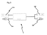
Figure 2 is a plan view of the device of the invention. - As can be schematically observed in
figure 1 , in general the invention relates todevices 1 to determine the voltage V interminals 2a and 2b of a firstphotovoltaic panel 2 and of the current I delivered thereby. - Specifically, and in a manner already known, these devices comprise:
- measuring means 4 of the current I,
- measuring means 5 of the voltage V,
- a first connection terminal 1a adapted to be connected to the
input terminal 2a of the firstphotovoltaic panel 2 and - a
second connection terminal 1b adapted to be connected to the output terminal 2b of the firstphotovoltaic panel 2, - Specifically, the device of the invention is characterized, with respect to said state of the art, in that it comprises:
- a
third connection terminal 1c adapted to be connected to the output terminal of a secondphotovoltaic panel 6, - a
fourth connection terminal 1d in parallel with thesecond connection terminal 1b and adapted to be connected to a thirdphotovoltaic panel 7, - the measuring means 4 of said current I being connected to said first and third terminals and the measuring means 5 of said voltage between the first and second terminals and
- wireless sending means 8 of the instantaneous current and voltage measured by said measuring means 4, 5 of the current and of the voltage.
- With these characteristics, it is possible to remotely know the operating point of a
photovoltaic panel 2 disposed in series with another twophotovoltaic panels - The remote sending means can be of any type by radiofrequency, or by GPRS or by any means suitable for sending information in real time. They can also be optical couplings in combination with data transmission cables, or a proximity reading system.
- As can be observed in
figure 2 , according to a preferred embodiment of the invention, thethird terminal 1c and thefourth terminal 1d are coupled male/female or coupled female/male respectively, the first terminal 1a and the third terminal are coupled male/female or coupled female/male respectively and the third terminal 13 and thefourth terminal 1d are coupled male/female or coupled female/male respectively. - In this way, a device is provided already prepared to be connected to an existing installation and which further permits its fast and easy interconnection with another device, as illustrated by the broken lines of
figure 1 . - As already mentioned, the device of the invention finds an especially advantageous application in photovoltaic solar power production installations, in particular in installations equipped with a plurality of photovoltaic panels connected in series, whether they are combined with arrangements in parallel or not.
- Thanks to its connections system, the device can be connected between adjacent panels or on the first or last panels, in this case substituting the connection with a panel by the connection with the input or output of the circuit of panels in series.
- The device also constitutes the base to carry out on the installation described a method of adaptation of the impedance of each one of the photovoltaic panels connected in series, by the following steps:
- Remotely obtaining the operating point of each panel using a device as claimed in
claims 1 to 4, - Dynamically adapting the impedance of each panel to obtain the maximum power delivered by the installation.
-
Figure 2 illustrates a particular embodiment of the device of the invention, wherein an ARISTON CA 402 N box and male type Tyco 6-1394461, and female type 5-1394462-5 connectors have been used.
Claims (7)
- Device (1) to determine the voltage (V) in terminals (2a, 2b) of a first photovoltaic panel (2) and of the current (I) delivered by it, equipped with- measuring means (4) of said current (I),- measuring means (5) of said voltage,- a first connection terminal (1a) adapted to be connected to the input terminal (2a) of the first photovoltaic panel (2),- a second connection terminal (1b) adapted to be connected to the output terminal (2b) of the first photovoltaic panel (2),characterized in that it comprises- a third connection terminal (1c) adapted to be connected to the output terminal of a second photovoltaic panel (6),- a fourth connection terminal (1d) in parallel with the second connection terminal (1b) and adapted to be connected to a third photovoltaic panel (7),- the measuring means (4) of said current (I) being connected to said first and third terminals and the measuring means (5) of said voltage between the first and second terminals,- wireless sending means (8) of the instantaneous current and voltage measured by said measuring means (4, 5) of the current and of the voltage,so that it is possible to remotely know the operating point of a photovoltaic panel (2) disposed in series with another two photovoltaic panels (6, 7).
- Device (1) according to the preceding claim wherein the third terminal (1c) and the fourth terminal (1d) are coupled male/female or coupled female/male respectively.
- Device (1) according to any of the preceding claims, wherein the first terminal (1a) and the third terminal are coupled male/female or coupled female/male respectively.
- Device (1) according to any of the preceding claims, wherein the third terminal (13) and the fourth terminal (1d) are coupled male/female or coupled female/male respectively.
- Installation for producing photovoltaic solar power equipped with a plurality of photovoltaic panels connected in series, which comprises a device according to any of claims 1 to 4 connected between two consecutive panels.
- Installation according to the preceding claim, which comprises a device according to any of claims 1 to 4 connected between the input of the array and the first panel and between the last panel and the output of the array.
- Method of adaptation of the impedance of an installation of photovoltaic panels connected in series, characterized in that the steps consist of:- Remotely obtaining the operating point of each panel using a device according to any of claims 1 to 4,- Adapting the impedance of each panel to obtain the maximum power delivered by the installation.
Applications Claiming Priority (1)
| Application Number | Priority Date | Filing Date | Title |
|---|---|---|---|
| ES200900449A ES2374462B1 (en) | 2009-02-18 | 2009-02-18 | DEVICE FOR DETERMINATION OF VOLTAGE AND CURRENTS DELIVERED BY A PHOTOVOLTAIC PANEL, PROVISIONED INSTALLATION OF SUCH DEVICE AND PROCEDURE FOR ADAPTATION OF IMPEDANCE FROM SUCH DEVICE. |
Publications (2)
| Publication Number | Publication Date |
|---|---|
| EP2221878A2 true EP2221878A2 (en) | 2010-08-25 |
| EP2221878A3 EP2221878A3 (en) | 2012-08-15 |
Family
ID=42334035
Family Applications (1)
| Application Number | Title | Priority Date | Filing Date |
|---|---|---|---|
| EP09163739A Withdrawn EP2221878A3 (en) | 2009-02-18 | 2009-06-25 | Device to determine the voltage and currents delivered by a photovoltaic panel, installation equipped with such a device and method of adaptation of the impedance from such a device |
Country Status (2)
| Country | Link |
|---|---|
| EP (1) | EP2221878A3 (en) |
| ES (1) | ES2374462B1 (en) |
Cited By (3)
| Publication number | Priority date | Publication date | Assignee | Title |
|---|---|---|---|---|
| CN102117076A (en) * | 2011-03-03 | 2011-07-06 | 北京天瑞星真空技术开发有限公司 | Solar tracking device |
| ITAN20120117A1 (en) * | 2012-09-21 | 2014-03-22 | Federico Cacciani | SENSOR FOR PHOTOVOLTAIC SYSTEMS. |
| CN104737028A (en) * | 2012-11-07 | 2015-06-24 | 伊顿公司 | Electrical joint monitoring device and system |
Family Cites Families (9)
| Publication number | Priority date | Publication date | Assignee | Title |
|---|---|---|---|---|
| DE19828560C2 (en) * | 1998-06-26 | 2000-05-25 | Fraunhofer Ges Forschung | Device for checking autonomous solar systems |
| JP3469807B2 (en) * | 1999-03-24 | 2003-11-25 | 鐘淵化学工業株式会社 | Solar cell power generation device, wiring device for the device, and wiring structure |
| US20030122558A1 (en) * | 2001-12-28 | 2003-07-03 | Hacke Peter L. | System and method for measuring photovoltaic cell conductive layer quality and net resistance |
| DE102005028513B4 (en) * | 2005-06-17 | 2020-01-16 | Sma Solar Technology Ag | Method for determining an interconnection type of at least two electrical devices and system with several electrical devices |
| JP5162737B2 (en) * | 2006-05-17 | 2013-03-13 | 英弘精機株式会社 | Solar cell characteristics evaluation system |
| US8013474B2 (en) * | 2006-11-27 | 2011-09-06 | Xslent Energy Technologies, Llc | System and apparatuses with multiple power extractors coupled to different power sources |
| WO2008124144A1 (en) * | 2007-04-06 | 2008-10-16 | Sunovia Energy Technologies, Inc. | Modular ac solar panel system |
| US20080306700A1 (en) * | 2007-06-07 | 2008-12-11 | Ekla-Tek L.L.C | Photvoltaic solar array health monitor |
| ES1066887Y (en) * | 2007-12-31 | 2008-06-16 | Helios Energy Europ S L | PHOTOVOLTAIC PANEL |
-
2009
- 2009-02-18 ES ES200900449A patent/ES2374462B1/en not_active Expired - Fee Related
- 2009-06-25 EP EP09163739A patent/EP2221878A3/en not_active Withdrawn
Cited By (4)
| Publication number | Priority date | Publication date | Assignee | Title |
|---|---|---|---|---|
| CN102117076A (en) * | 2011-03-03 | 2011-07-06 | 北京天瑞星真空技术开发有限公司 | Solar tracking device |
| CN102117076B (en) * | 2011-03-03 | 2012-09-05 | 北京天瑞星光热技术有限公司 | Solar tracking device |
| ITAN20120117A1 (en) * | 2012-09-21 | 2014-03-22 | Federico Cacciani | SENSOR FOR PHOTOVOLTAIC SYSTEMS. |
| CN104737028A (en) * | 2012-11-07 | 2015-06-24 | 伊顿公司 | Electrical joint monitoring device and system |
Also Published As
| Publication number | Publication date |
|---|---|
| EP2221878A3 (en) | 2012-08-15 |
| ES2374462B1 (en) | 2012-09-27 |
| ES2374462A1 (en) | 2012-02-17 |
Similar Documents
| Publication | Publication Date | Title |
|---|---|---|
| US10431988B2 (en) | Alternative source module array characterization | |
| US9105765B2 (en) | Smart junction box for a photovoltaic system | |
| US6339538B1 (en) | Inverter circuit and method of operation | |
| US11774473B2 (en) | Systems for electrically connecting metering devices and distributed energy resource devices | |
| US8446042B2 (en) | Photovoltaic array systems, methods, and devices with improved diagnostics and monitoring | |
| US20120049879A1 (en) | Active and passive monitoring system for installed photovoltaic strings, substrings, and modules | |
| CN101253665B (en) | Method for determining the type of connection of at least two electrical devices and system comprising several electric devices | |
| CN102400849A (en) | Frequency conversion wind power equipment | |
| US20130274946A1 (en) | Methods and systems for controlling a power plant | |
| US20110224839A1 (en) | Power Point Tracking | |
| US9267973B2 (en) | Power generating component connectivity resistance | |
| CN107064648B (en) | The detection device and method of the lightning-arrest lead resistance value of blower fan pylon based on leakage cable | |
| US20130234516A1 (en) | Electricity generation controller, electricity generation control system, and electricity generation control method | |
| CN109307851B (en) | Online calibration device for voltage transformer error | |
| EP2221878A2 (en) | Device to determine the voltage and currents delivered by a photovoltaic panel, installation equipped with such a device and method of adaptation of the impedance from such a device | |
| CN102640008B (en) | Method and device for calculating the input voltage of a distribution station of an electrical network | |
| US20200162023A1 (en) | Active and passive monitoring system for installed photovoltaic strings, substrings, and modules | |
| CN207866954U (en) | Electric cable failure detector | |
| EP3486665B1 (en) | Remote measurement of electrical active power | |
| JP2013038345A (en) | Photovoltaic power generation system | |
| CN219394799U (en) | Photovoltaic module generating capacity measurement system under sea surface floating environment | |
| KR101516344B1 (en) | Apparatus of the performance verification for renewable energy module by a unit module and method thereof | |
| KR20150033469A (en) | multi channel measuring system employing wireless communication terminal housing of solar power generation apparatus | |
| CN113949097B (en) | A photovoltaic power station energy efficiency analysis system | |
| CN109555652B (en) | Data monitoring system for wind generating set |
Legal Events
| Date | Code | Title | Description |
|---|---|---|---|
| PUAI | Public reference made under article 153(3) epc to a published international application that has entered the european phase |
Free format text: ORIGINAL CODE: 0009012 |
|
| AK | Designated contracting states |
Kind code of ref document: A2 Designated state(s): AT BE BG CH CY CZ DE DK EE ES FI FR GB GR HR HU IE IS IT LI LT LU LV MC MK MT NL NO PL PT RO SE SI SK TR |
|
| AX | Request for extension of the european patent |
Extension state: AL BA RS |
|
| PUAL | Search report despatched |
Free format text: ORIGINAL CODE: 0009013 |
|
| RIC1 | Information provided on ipc code assigned before grant |
Ipc: H01L 31/042 20060101AFI20120705BHEP Ipc: G01R 31/40 20060101ALI20120705BHEP |
|
| AK | Designated contracting states |
Kind code of ref document: A3 Designated state(s): AT BE BG CH CY CZ DE DK EE ES FI FR GB GR HR HU IE IS IT LI LT LU LV MC MK MT NL NO PL PT RO SE SI SK TR |
|
| AX | Request for extension of the european patent |
Extension state: AL BA RS |
|
| 17P | Request for examination filed |
Effective date: 20130215 |
|
| 17Q | First examination report despatched |
Effective date: 20160916 |
|
| STAA | Information on the status of an ep patent application or granted ep patent |
Free format text: STATUS: EXAMINATION IS IN PROGRESS |
|
| STAA | Information on the status of an ep patent application or granted ep patent |
Free format text: STATUS: THE APPLICATION IS DEEMED TO BE WITHDRAWN |
|
| 18D | Application deemed to be withdrawn |
Effective date: 20170328 |