EP2221650A1 - Optical fibre distribution cabinet - Google Patents
Optical fibre distribution cabinet Download PDFInfo
- Publication number
- EP2221650A1 EP2221650A1 EP10154381A EP10154381A EP2221650A1 EP 2221650 A1 EP2221650 A1 EP 2221650A1 EP 10154381 A EP10154381 A EP 10154381A EP 10154381 A EP10154381 A EP 10154381A EP 2221650 A1 EP2221650 A1 EP 2221650A1
- Authority
- EP
- European Patent Office
- Prior art keywords
- distribution cabinet
- splice
- optical waveguide
- module
- cabinet according
- Prior art date
- Legal status (The legal status is an assumption and is not a legal conclusion. Google has not performed a legal analysis and makes no representation as to the accuracy of the status listed.)
- Withdrawn
Links
- 239000013307 optical fiber Substances 0.000 title description 19
- 239000000835 fiber Substances 0.000 claims abstract description 41
- 230000003287 optical effect Effects 0.000 claims description 34
- 239000002184 metal Substances 0.000 claims description 2
- 239000007769 metal material Substances 0.000 claims description 2
- 239000000843 powder Substances 0.000 claims description 2
- 239000002516 radical scavenger Substances 0.000 claims 1
- 238000009434 installation Methods 0.000 description 6
- 238000005452 bending Methods 0.000 description 5
- 238000011161 development Methods 0.000 description 3
- 230000018109 developmental process Effects 0.000 description 3
- 238000003780 insertion Methods 0.000 description 3
- 230000037431 insertion Effects 0.000 description 3
- 238000012856 packing Methods 0.000 description 3
- 230000008878 coupling Effects 0.000 description 2
- 238000010168 coupling process Methods 0.000 description 2
- 238000005859 coupling reaction Methods 0.000 description 2
- RYGMFSIKBFXOCR-UHFFFAOYSA-N Copper Chemical compound [Cu] RYGMFSIKBFXOCR-UHFFFAOYSA-N 0.000 description 1
- 230000000712 assembly Effects 0.000 description 1
- 238000000429 assembly Methods 0.000 description 1
- 239000003086 colorant Substances 0.000 description 1
- 210000001520 comb Anatomy 0.000 description 1
- 230000002349 favourable effect Effects 0.000 description 1
- 239000003365 glass fiber Substances 0.000 description 1
- 238000012423 maintenance Methods 0.000 description 1
- 238000005259 measurement Methods 0.000 description 1
- 238000000034 method Methods 0.000 description 1
- 230000035515 penetration Effects 0.000 description 1
- 229920001296 polysiloxane Polymers 0.000 description 1
- 239000007921 spray Substances 0.000 description 1
Images

Classifications
-
- G—PHYSICS
- G02—OPTICS
- G02B—OPTICAL ELEMENTS, SYSTEMS OR APPARATUS
- G02B6/00—Light guides; Structural details of arrangements comprising light guides and other optical elements, e.g. couplings
- G02B6/44—Mechanical structures for providing tensile strength and external protection for fibres, e.g. optical transmission cables
- G02B6/4439—Auxiliary devices
- G02B6/444—Systems or boxes with surplus lengths
- G02B6/4453—Cassettes
- G02B6/4455—Cassettes characterised by the way of extraction or insertion of the cassette in the distribution frame, e.g. pivoting, sliding, rotating or gliding
-
- G—PHYSICS
- G02—OPTICS
- G02B—OPTICAL ELEMENTS, SYSTEMS OR APPARATUS
- G02B6/00—Light guides; Structural details of arrangements comprising light guides and other optical elements, e.g. couplings
- G02B6/44—Mechanical structures for providing tensile strength and external protection for fibres, e.g. optical transmission cables
- G02B6/4439—Auxiliary devices
- G02B6/444—Systems or boxes with surplus lengths
- G02B6/4452—Distribution frames
- G02B6/44524—Distribution frames with frame parts or auxiliary devices mounted on the frame and collectively not covering a whole width of the frame or rack
-
- G—PHYSICS
- G02—OPTICS
- G02B—OPTICAL ELEMENTS, SYSTEMS OR APPARATUS
- G02B6/00—Light guides; Structural details of arrangements comprising light guides and other optical elements, e.g. couplings
- G02B6/44—Mechanical structures for providing tensile strength and external protection for fibres, e.g. optical transmission cables
- G02B6/4439—Auxiliary devices
- G02B6/444—Systems or boxes with surplus lengths
- G02B6/44528—Patch-cords; Connector arrangements in the system or in the box
Definitions
- the invention relates to an optical waveguide distribution cabinet according to the preamble of claim 1.
- Fiber optic (LWL) distribution systems usually consist of splice boxes, cable trunking and cable gripping rails, which are arranged in a distributor housing.
- the receiving chambers referred to as splice boxes, serve for separating the installed parts into input and output-side subregions.
- the height of the splice boxes for distributing a plurality of optical waveguides determines the overall height of the entire distribution system.
- a splice splitter for fiber optic (FO) fiber optic splicing combs known in which the fiber optic fibers are distributed from incoming fiber optic cables or fiber optic bundles and can be connected to outgoing fiber optic single fibers.
- the outdoor cables, the fiber optic bundles and the individual fiber optic fibers can be arranged strain-relieved in a housing.
- a compact unit is formed from a base carrier plate, a plurality of carrier plates, each with at least one optical fiber splice distributor and a lid, which are stacked on a small mounting surface.
- the carrier plates offer the possibility of a strain-relieved supply of fiber optic outdoor cables, consisting of fiber optic bundles with a variety of individual fibers.
- an optical fiber splice box designed as forward and top open fiber splice extract. This is installed with two-part telescopic extensions in an open to the front rack.
- a front panel with fiber optic couplings is hinged in the region of the front lower edge of the splice extract and can be locked by means of releasable closure elements in the closed position on the splice extractor.
- FO splice cassettes are arranged one above the other on an intermediate floor of the splice extractor. In the bottom area of the splice tray is below the splice cassettes a storage compartment for jumper lines or the like is formed.
- DE 102 10 778 B4 a housing or frame with a cable management device for fiber optic cable with at least one guide lug with rounded deflection, which is attached to a support body of this with its axis of curvature perpendicularly projecting.
- the support body is a substantially rectangular horizontal support plate. In the direction of a glass fiber to be placed corresponding deflecting units are arranged.
- the support plate for attachment to frame legs or mounting rails of the housing or frame has attachment portions and is provided with downwardly bent further deflection sections. Such a deflection is favorable, for example, when fiber optic cables are connected to a front side or rear side of a horizontally arranged installation housing and then to be guided upwards or downwards.
- the invention includes an optical fiber distribution cabinet with splice modules arranged in a housing, wherein a splice module stack is formed from a number of splice modules arranged vertically one above the other and at least one splice module can be swung outwardly out of the splice module stack via a vertical axis.
- the solution according to the invention is an optical waveguide distribution cabinet, also referred to as ODF from the English-speaking world ( o ptical d istribution f rame).
- the housing of a distribution cabinet designed as a cupboard, includes a cover in the bottom and lid area, optionally side panels.
- a front front door is either one-piece or multi-part designed to ensure easier access to frequently frequented areas in the distribution cabinet. Most such distribution cabinets are operated from the front. Further designed is an insertion cable channel for optical fibers to ensure a separate management of the incoming and outgoing cables.
- all splice modules can also be designed to swing outward over a vertical axis.
- a vertical axis usually viewed from the front side, arranged on the right or left side hinges.
- module stacks in which the respective splicing modules in the stack can be pivoted alternately about a vertical axis.
- the splice modules may be rotatable individually or as whole stacking parts in the package alternately on the left and right sides. When folded, locking devices on the splicing module can also ensure a defined closed position.
- a splice module is easily swung out of the splice module stack, thereby facilitating access to the splice cassettes usually mounted on the bottom plate of the splice module.
- the wiring of the splice module in particular the connection of the fiber optic couplings, is easily possible in this way.
- the post-wiring further distribution by means of so-called patch cables or jumper lines is also carried out advantageously, since these can also be stored in stock on the guide elements.
- a particular advantage of the solution according to the invention is that the optical waveguide distribution cabinet due to The stacked units have a high packing density and ease of use. Since each splice module can be swung out for itself, a clear sub-unit of a subrack is created in the large number of cables to be laid. A quick and easy installation of the individual optical fibers is guaranteed.
- the solution according to the invention thus comes with a pivoting process, in which the distances traveled are limited so that compared to conventional splice distributors must be worked with little or no cable excess length.
- the cables also do not need to be tracked during installation due to their smaller distances.
- each splice module can have a half height unit.
- One height unit as a standardized unit of measurement for the height of an electronics housing corresponds to 13 ⁇ 4 inches.
- Each splice module can store up to 24 fibers via connectors. As a result, a particularly compact unit is formed with a very high packing density.
- the splice module can be made of a metallic material, dip primed and powder coated.
- a cable interception plate may be arranged below the splice modules. about The cable interception plate are guided on the input side cable bundles and prepared accordingly for further distribution. Such Jardinabfangplatten edge can also be designed according bent to accommodate the cable tangential as possible on the plate and forward without kinks. The optical waveguides are guided on the input side as well as for further distribution of the bundles on the output side over the intercepting plate over allowed bending radii. This supports an orderly and clear cable routing in the fiber optic distribution cabinet.
- a catch device for fiber central elements can be arranged on the cable interception plate.
- the cable bundles are fixed in the open state for strain relief.
- the central elements of the cables can be attached to clamps as a cable clamp, which are arranged on the cable clamp plate.
- the cables may be routed along the splice module stacks in guide tubes.
- unique assignable cable guides are created starting from the cable clamp.
- a module can be addressed in each of the guide tubes and distinguishable on the input side.
- Such guide tubes can be, for example, so-called mini-flex hoses, each of which addresses a specific module and is color-coded on the introduction side. In this way, the deflection radius of the fibers and the permissible bending radii are maintained.
- up to 24 fibers can be connected in one splice module.
- two splice cassettes can be arranged for every 12 fibers.
- Another advantage may result if two splice cassettes for every 12 fibers are arranged in a splice module.
- guide elements can be arranged laterally on the splice module stack along one of the side walls of the housing, via which patch cables can be guided to the respective splice module.
- Such barrel-shaped guide or deflecting elements are designed so that the Cable can be deflected without kinks in an adequate radius and guided in the distribution cabinet.
- the excess lengths of the cables are deposited on such guide elements due to the different lengths of connections.
- 72 splice modules can be arranged. This corresponds to a splice module stack having a height of 63 inches or about 160 cm. As a result, up to 1728 optical fiber fibers can be stored in the distribution cabinet. In addition, it is also conceivable to arrange 78 or 84 splice modules in the splice module stack.
- the guide tubes may be mounted in a comb-like structure on a side wall of the manifold, thereby providing the easy way to remove the guide tubes from the structure. This is further facilitated by the fact that the guide tubes are laid without crossing in the comb-like structure.
- the vertical axis is arranged in such a way that it runs between the rear wall of the distribution cabinet and the patch cables connected to the splicing module.
- the described arrangement of the vertical axis, the connection cable or the optical waveguide are more accessible without the arrangement of the vertical axis interferes, for example, during maintenance or splicing.
- the optical waveguide distribution cabinet according to the invention is equipped with a module holder, in particular for the attachment of splitter modules.
- This module holder can be arranged for example on the upper end side of the optical waveguide distribution cabinet and be formed of a suitably shaped sheet metal part optionally with studs for screwing modules such as splitter modules.
- the module holder can be arranged hanging from the upper end side of the distribution cabinet according to the invention or standing on this standing.
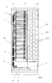
- Fig. 1 schematically shows a front view of an optical fiber distribution cabinet 1.
- the housing 2 of the distribution cabinet 1 is designed as a free-standing cabinet with a bottom cover 21 and a cover cover 22 and provided with vertical side panels 24.
- the distribution cabinet 1 is accessible from the front, which can optionally be closed with a front door.
- the connection and outgoing cables are passed through, not shown in the figure, cable penetrations centrally via recesses on the housing 2.
- connection cables are routed to a cable interception plate 3 for the cable clamp 31.
- the opened cable bundles are inserted into mini flex hoses 41 as guide tubes.
- Each cable bundle is advanced in the mini flex hose 41 to the respective splice module 7.
- the drawer of the splice module 7 is swung out and pulled the cable bundle in compliance with the allowable bending radius, until the bundle on the cable clamp plate 3 is pulled smoothly.
- the loop in the splice tray requires about 160 cm of cable to connect.
- the optical fibers are inserted in a splice cassette 72 of a splice module 7.
- the loose tubes must be opened and cleaned with a suitable tool in order to prepare them for splicing.
- the splicing modules 7, which are pivotable about a vertical axis A from the splice module stack 8, ensure easy access when laying and connecting the optical fibers.
- guide elements 6 are arranged for the forwarding of the individual fiber optic fibers.
- guide elements 6 is a guide comb 61 and two rows of drums 62 on which the excess lengths of the patch cables can be stored.
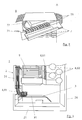
- Fig. 2 shows a schematic representation of a splice module stack 8 with pivotable splice modules 7.
- the top splice module 7 is opened from the splice module stack 8 for storing the loose tubes.
- a splicing module 7 is pivoted out about the vertical axis A by means of a rotary joint. Via a cable feed 73, the incoming loose tubes can be routed to splice module 7 with a given radius.
- two mini-flex hoses each lead two bundles of cables to form a splicing module 7.
- the splicing module typically contains two splice cassettes 72 in order to connect 2 ⁇ 12 optical fibers or patch cords to the connectors 71. For cable routing between the splice cassettes 72 guide tubes not shown in the figures are used.
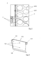
- Fig. 3 shows a schematic detail view of an optical waveguide distribution cabinet 1 in the region of an arranged in the housing 2 input side cable interceptor 3rd
- connection cables are routed to a cable interception plate 3 for the cable clamp 31.
- the fiber optic cables are opened and their central fiber elements for strain relief, for example with a cable clamp, fixed accordingly.
- the cable clamp plate 3 is bent to the bottom cover 21 out with a sufficiently large bending radius as bending control to avoid kinks in the connection cable.
- each bundle of cables in the mini flex hose 41 is inserted as far as the respective splicing module 7 until it strikes the splicing module 7.
- the splice module stack 8 is located above the cable interceptor plate 3.
- a guide comb 61 and a part of the drums 62 are shown as guide elements 6 for the forwarding of the individual fiber optic fibers from the lower region of the splice module stack 8.
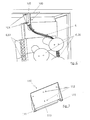
- FIG. 4 shows a schematic detail view of an optical waveguide distribution cabinet 1 in the region of the output-side guide elements 6.
- the output side connected optical waveguide 5 are shown. These are bundled over the guide comb 61 and fed to the drums 62. On these drums 62 also over a storage scheme ordered overlengths of the connection or patch cables are stored. It is particularly advantageous that the in FIG. 4 not shown rotary axis A behind the optical waveguides or behind the patch cables runs, so that the insertion of the patch cable is substantially facilitated by the fact that they do not have to be passed behind the axis of rotation A, but can be performed in the splice tray.
- Fig. 5 shows an embodiment of a module holder 100 in a perspective view, in which it is provided for hanging installation.
- the module holder 100 shows the mounting tabs 101 for Screwing, for example, with the frame of the manifold and the holes 102 for performing, for example, in FIG. 5 Stud bolts 104, not shown, for bolting a module such as a splitter module (in Fig. 6 not shown).
- the curved end section 103 of the module holder 100 serves to predetermine a setpoint radius for optical waveguides led out, for example, from splitter modules.
- Fig. 6 shows a partial view of the upper portion of an optical waveguide distribution cabinet according to the invention, in which the module holder 100 from Fig. 5 is arranged hanging in the upper area.
- Well recognizable in Fig. 6 is the splitter module 105 arranged on the stud bolt 104 and the optical waveguide guided along the end portion 103.
- Fig. 7 shows an embodiment of the module holder 110 for standing attachment to an optical waveguide distribution cabinet according to the invention.
- the stationary module holder 110 shows bores 112 and fastening tabs 111.
- module holder 110 has a bent portion 113 for guiding optical fibers.
- Fig. 8 is the in Fig. 7 shown variant to illustrate the installation situation standing on a fiber optic distribution cabinet 1 shown.
Abstract
Description
Die Erfindung betrifft einen Lichtwellenleiter-Verteilerschrank gemäß dem Oberbegriff des Anspruchs 1.The invention relates to an optical waveguide distribution cabinet according to the preamble of
Verteilersysteme von Lichtwellenleitern (LWL) bestehen zumeist aus Spleißboxen, Kabelführungskanälen und Kabelabfangschienen, die in einem Verteilergehäuse angeordnet sind. Bei den bekannten Lichtwellenleiter-Verteilern dienen die als Spleißboxen bezeichneten Aufnahmekammern zur Trennung der eingebauten Teile in eingangs- und ausgangsseitige Teilbereiche. Die Höhe der Spleißboxen zur Verteilung einer Vielzahl von Lichtwellenleitern bestimmt unter anderem die Bauhöhe des gesamten Verteilersystems.Fiber optic (LWL) distribution systems usually consist of splice boxes, cable trunking and cable gripping rails, which are arranged in a distributor housing. In the known optical waveguide distributors, the receiving chambers, referred to as splice boxes, serve for separating the installed parts into input and output-side subregions. Among other things, the height of the splice boxes for distributing a plurality of optical waveguides determines the overall height of the entire distribution system.
Aus der
Des Weiteren ist aus der
Auch bekannt sind aus
Es ist Aufgabe der Erfindung, einen Lichtwellenleiter-Verteilerschrank mit hoher Packungsdichte zu schaffen, bei dem Spleißmodule leicht zugänglich sind und alle erforderlichen Zu- und Abführleitungen übersichtlich untergebracht werden können.It is an object of the invention to provide a fiber optic distribution cabinet with high packing density, in which splice modules are easily accessible and all required supply and discharge lines can be clearly arranged.
Erfindungsgemäß wird diese Aufgabe mit den in Anspruch 1 genannten Merkmalen gelöst. Die weiteren rückbezogenen Ansprüche betreffen vorteilhafte Aus- und Weiterbildungen der Erfindung.According to the invention this object is achieved with the features mentioned in
Die Erfindung schließt einen Lichtwellenleiter-Verteilerschrank ein, mit in einem Gehäuse angeordneten Spleißmodulen, wobei aus einer Anzahl von vertikal übereinander angeordneten Spleißmodulen ein Spleißmodulstapel ausgebildet ist und zumindest ein Spleißmodul über eine vertikale Achse aus dem Spleißmodulstapel nach außen ausschwenkbar ist.The invention includes an optical fiber distribution cabinet with splice modules arranged in a housing, wherein a splice module stack is formed from a number of splice modules arranged vertically one above the other and at least one splice module can be swung outwardly out of the splice module stack via a vertical axis.
Bei der erfindungsgemäßen Lösung handelt es sich um einen Lichtwellenleiter-Verteilerschrank, aus dem englischen Sprachraum übernommen auch als ODF bezeichnet (optical distribution frame).The solution according to the invention is an optical waveguide distribution cabinet, also referred to as ODF from the English-speaking world ( o ptical d istribution f rame).
Das Gehäuse eines Verteilerschranks, ausgeführt als Standschrank, umfasst eine Abdeckung im Boden- und Deckelbereich, optional auch Seitenteile. Eine vordere Fronttüre ist entweder einteilig oder auch mehrteilig ausgeführt, um einen erleichterten Zugang zu öfter frequentierten Teilbereichen im Verteilerschrank zu gewährleisten. Meist werden derartige Verteilerschränke von der Frontseite aus bedient. Weiter ausgebildet ist ein Einführungskabelkanal für Lichtwellenleiter, um eine getrennte Führung der ankommenden und abgehenden Kabel zu gewährleisten.The housing of a distribution cabinet, designed as a cupboard, includes a cover in the bottom and lid area, optionally side panels. A front front door is either one-piece or multi-part designed to ensure easier access to frequently frequented areas in the distribution cabinet. Most such distribution cabinets are operated from the front. Further designed is an insertion cable channel for optical fibers to ensure a separate management of the incoming and outgoing cables.
In einem Modulstapel können auch alle Spleißmodule über eine vertikale Achse nach außen ausschwenkbar ausgeführt sein. Hierzu sind meist, von der Frontseite aus betrachtet, auf der rechten oder linken Seite Drehgelenke angeordnet. Denkbar sind allerdings auch Modulstapel, bei denen die jeweiligen Spleißmodule im Stapel alternierend um eine vertikale Achse schwenkbar sind. Mit anderen Worten, die Spleißmodule können im Spleißmodulstapel, von der Frontseite her betrachtet, einzeln oder als ganze Stapelteile im Paket wechselseitig auf der linken bzw. rechten Seite drehbar ausgeführt sein. Im eingeklappten Zustand können auch Arretierungseinrichtungen am Spleißmodul für eine definierte Schließstellung sorgen.In a module stack, all splice modules can also be designed to swing outward over a vertical axis. For this purpose, usually viewed from the front side, arranged on the right or left side hinges. Also conceivable, however, are module stacks in which the respective splicing modules in the stack can be pivoted alternately about a vertical axis. In other words, in the splice module stack, as viewed from the front side, the splice modules may be rotatable individually or as whole stacking parts in the package alternately on the left and right sides. When folded, locking devices on the splicing module can also ensure a defined closed position.
Ein Spleißmodul ist leicht aus dem Spleißmodulstapel ausschwenkbar, wodurch der Zugang zu den üblicherweise auf dem Bodenblech des Spleißmoduls befestigten Spleißkassetten erleichtert wird. Die Verdrahtung des Spleißmoduls, insbesondere der Anschluss der LWL-Kupplungen, ist auf diese Weise einfach möglich. Die nach der Verdrahtung erfolgende weitere Verteilung mit Hilfe von sogenannten Patchkabeln oder Rangierleitungen ist ebenfalls vorteilhaft ausgeführt, da diese auf den Führungselementen auch vorrätig abgelegt werden können.A splice module is easily swung out of the splice module stack, thereby facilitating access to the splice cassettes usually mounted on the bottom plate of the splice module. The wiring of the splice module, in particular the connection of the fiber optic couplings, is easily possible in this way. The post-wiring further distribution by means of so-called patch cables or jumper lines is also carried out advantageously, since these can also be stored in stock on the guide elements.
Ein besonderer Vorteil der erfindungsgemäßen Lösung ist, dass der Lichtwellenleiter-Verteilerschrank aufgrund der gestapelten Baueinheiten eine hohe Packungsdichte und Bedienerfreundlichkeit aufweist. Da jedes Spleißmodul für sich ausschwenkbar ist, wird bei der Vielzahl der zu verlegenden Kabel eine übersichtliche Untereinheit eines Baugruppenträgers geschaffen. Ein schneller und einfacher Einbau der einzelnen Lichtwellenleiter ist dadurch gewährleistet.A particular advantage of the solution according to the invention is that the optical waveguide distribution cabinet due to The stacked units have a high packing density and ease of use. Since each splice module can be swung out for itself, a clear sub-unit of a subrack is created in the large number of cables to be laid. A quick and easy installation of the individual optical fibers is guaranteed.
Die erfindungsgemäße Lösung kommt also mit einem Schwenkvorgang aus, bei dem die zurückgelegten Wegstrecken so begrenzt sind, dass gegenüber herkömmlichen Spleißverteilern nur mit geringer oder gar keiner Kabelüberlänge gearbeitet werden muss. Die Kabel müssen durch geringere Wegstecken beim Verlegen auch nicht nachgeführt werden.The solution according to the invention thus comes with a pivoting process, in which the distances traveled are limited so that compared to conventional splice distributors must be worked with little or no cable excess length. The cables also do not need to be tracked during installation due to their smaller distances.
In besonders bevorzugter Ausführungsform kann jedes Spleißmodul eine halbe Höheneinheit aufweisen. Eine Höheneinheit als standardisierte Maßeinheit für die Höhe eines Elektronikgehäuses entspricht 1¾ Zoll. In jedem Spleißmodul können hierbei über Stecker bis zu 24 Fasern abgelegt werden. Hierdurch wird eine besonders kompakte Einheit mit sehr hoher Packungsdichte gebildet. Das Spleißmodul kann dabei aus einem metallischen Werkstoff hergestellt, tauchgrundiert und pulverbeschichtet sein.In a particularly preferred embodiment, each splice module can have a half height unit. One height unit as a standardized unit of measurement for the height of an electronics housing corresponds to 1¾ inches. Each splice module can store up to 24 fibers via connectors. As a result, a particularly compact unit is formed with a very high packing density. The splice module can be made of a metallic material, dip primed and powder coated.
In bevorzugter Ausführungsform kann eine Kabelabfangplatte unterhalb der Spleißmodule angeordnet sein. Über die Kabelabfangplatte werden die eingangsseitigen Kabelbündel geführt und entsprechend zur weiteren Verteilung vorbereitet. Derartige Kabelabfangplatten können randseitig auch entsprechend gebogen ausgeführt sein, um die Kabel auf der Platte möglichst tangential aufzunehmen und ohne Knickstellen weiterzuleiten. Die Lichtwellenleiter werden so über erlaubte Biegeradien sowohl eingangsseitig als auch zur weiteren Verteilung der Bündel ausgangsseitig über die Abfangplatte geführt. Hierdurch wird eine geordnete und übersichtliche Kabelführung im LWL-Verteilerschrank unterstützt.In a preferred embodiment, a cable interception plate may be arranged below the splice modules. about The cable interception plate are guided on the input side cable bundles and prepared accordingly for further distribution. Such Kabelabfangplatten edge can also be designed according bent to accommodate the cable tangential as possible on the plate and forward without kinks. The optical waveguides are guided on the input side as well as for further distribution of the bundles on the output side over the intercepting plate over allowed bending radii. This supports an orderly and clear cable routing in the fiber optic distribution cabinet.
Vorteilhafterweise kann auf der Kabelabfangplatte eine Abfangeinrichtung für Faser-Zentralelemente angeordnet sein. So werden die Kabelbündel im geöffneten Zustand zur Zugentlastung fixiert. Hierzu können die Zentralelemente der Kabel an Schellen als Kabelabfangung befestigt werden, die auf der Kabelabfangplatte angeordnet sind.Advantageously, a catch device for fiber central elements can be arranged on the cable interception plate. Thus, the cable bundles are fixed in the open state for strain relief. For this purpose, the central elements of the cables can be attached to clamps as a cable clamp, which are arranged on the cable clamp plate.
In einer vorteilhaften Ausgestaltung der Erfindung können im Anschluss an die Kabelabfangplatte die Kabel in Führungsschläuchen am Spleißmodulstapel entlang geführt sein. Hierdurch werden ausgehend von der Kabelabfangplatte eindeutig zuordenbare Kabelführungen angelegt.In an advantageous embodiment of the invention, following the cable interception plate, the cables may be routed along the splice module stacks in guide tubes. As a result, unique assignable cable guides are created starting from the cable clamp.
In einer weiteren vorteilhaften Ausführungsform kann in jeden der Führungsschläuche ein Modul adressiert und auf der Eingangsseite unterscheidbar gekennzeichnet sein. Zur Unterscheidbarkeit können unterschiedliche Farbgebungen verwendet werden. Derartige Führungsschläuche können beispielsweise sogenannte Miniflexschläuche sein, von denen jedes einzelne ein bestimmtes Modul adressiert und auf der Einführungsseite farblich gekennzeichnet ist. Auf diese Weise werden bei der Umlenkung der Fasern auch die zulässigen Biegeradien eingehalten.In a further advantageous embodiment, a module can be addressed in each of the guide tubes and distinguishable on the input side. For distinctness different colors can be used. Such guide tubes can be, for example, so-called mini-flex hoses, each of which addresses a specific module and is color-coded on the introduction side. In this way, the deflection radius of the fibers and the permissible bending radii are maintained.
Vorteilhafterweise können in einem Spleißmodul bis zu 24 Fasern angeschlossen sein. In einem Modul können zwei Spleißkassetten für jeweils 12 Fasern angeordnet sein. Derartige kleine Baugruppen gewährleisten eine übersichtliche Handhabung beim Anschließen der Lichtwellenleiter aus Kabelbündeln an der Frontseite eines Spleißmodulstapels. Hierdurch werden Montagezeiten wesentlich reduziert.Advantageously, up to 24 fibers can be connected in one splice module. In one module, two splice cassettes can be arranged for every 12 fibers. Such small assemblies ensure a clear handling when connecting the optical fibers from cable bundles on the front of a splice module stack. As a result, assembly times are significantly reduced.
Ein weiterer Vorteil kann resultieren, wenn in einem Spleißmodul zwei Spleißkassetten für jeweils 12 Fasern angeordnet sind.Another advantage may result if two splice cassettes for every 12 fibers are arranged in a splice module.
In einer vorteilhaften Weiterbildung der Erfindung können seitlich am Spleißmodulstapel Führungselemente entlang einer der Seitenwände des Gehäuses angeordnet sein, über die Patchkabel zum jeweiligen Spleißmodul geführt werden können. Derartige tonnenförmige Führungs- oder Umlenkelemente sind so gestaltet, dass die Kabel ohne Knickstellen in ausreichendem Radius umgelenkt und im Verteilerschrank geführt werden können. Insbesondere bei einheitlich langen Patchkabeln werden aufgrund der unterschiedlich langen Anschlüsse die Überlängen der Kabel auf derartigen Führungselementen abgelegt.In an advantageous development of the invention, guide elements can be arranged laterally on the splice module stack along one of the side walls of the housing, via which patch cables can be guided to the respective splice module. Such barrel-shaped guide or deflecting elements are designed so that the Cable can be deflected without kinks in an adequate radius and guided in the distribution cabinet. Especially with uniformly long patch cables, the excess lengths of the cables are deposited on such guide elements due to the different lengths of connections.
Vorteilhafterweise können 72 Spleißmodule angeordnet sein. Dies entspricht einem Spleißmodulstapel mit einer Höhe von 63 Zoll bzw. ungefähr 160 cm. Hierdurch können im Verteilerschrank bis zu 1728 Lichtwellenleiterfasern abgelegt werden. Daneben ist es auch denkbar, 78 oder 84 Spleißmodule in dem Spleißmodulstapel anzuordnen.Advantageously, 72 splice modules can be arranged. This corresponds to a splice module stack having a height of 63 inches or about 160 cm. As a result, up to 1728 optical fiber fibers can be stored in the distribution cabinet. In addition, it is also conceivable to arrange 78 or 84 splice modules in the splice module stack.
Die Führungsschläuche können in einer kammartigen Struktur an einer Seitenwand des Verteilerschranks gehaltert sein, wodurch sich die einfache Möglichkeit ergibt, die Führungsschläuche aus der Struktur zu entnehmen. Dies wird dadurch weiter erleichtert, dass die Führungsschläuche in der kammartigen Struktur kreuzungsfrei verlegt sind.The guide tubes may be mounted in a comb-like structure on a side wall of the manifold, thereby providing the easy way to remove the guide tubes from the structure. This is further facilitated by the fact that the guide tubes are laid without crossing in the comb-like structure.
Hierdurch wird die Möglichkeit geschaffen, ein Spleißmodul aus dem Spleißmodulstapel vollständig herauszunehmen, was insbesondere durch die leichte Entnehmbarkeit der Führungsschläuche aus der kammartigen Struktur und ihre kreuzungsfreie Führung erleichtert wird.In this way, the possibility is created to completely remove a splice module from the splice module stack, which is facilitated in particular by the easy removability of the guide tubes from the comb-like structure and their crossing-free guidance.
Daneben ist es von Vorteil, wenn die vertikale Achse in der Weise angeordnet ist, dass sie zwischen der Rückwand des Verteilerschrankes und den an das Spleißmodul angeschlossenen Patchkabeln verläuft. Durch die beschriebene Anordnung der vertikalen Achse werden die Anschlusskabel bzw. die Lichtwellenleiter besser zugänglich, ohne dass sich die Anordnung der vertikalen Achse störend beispielsweise bei Wartungs- oder Spleißarbeiten auswirkt.In addition, it is advantageous if the vertical axis is arranged in such a way that it runs between the rear wall of the distribution cabinet and the patch cables connected to the splicing module. The described arrangement of the vertical axis, the connection cable or the optical waveguide are more accessible without the arrangement of the vertical axis interferes, for example, during maintenance or splicing.
In einer weiteren vorteilhaften Ausführungsform der Erfindung ist der erfindungsgemäße Lichtwellenleiter-Verteilerschrank mit einer Modulhalterung insbesondere zur Anbringung von Splittermodulen ausgestattet. Diese Modulhalterung kann beispielsweise an der oberen Stirnseite des Lichtwellenleiter-Verteilerschranks angeordnet sein und aus einem geeignet geformten Blechteil gegebenenfalls mit Stehbolzen zur Verschraubung von Modulen wie beispielsweise Splittermodulen ausgebildet sein. Die Modulhalterung kann von der oberen Stirnseite des erfindungsgemäßen Verteilerschranks nach innen hängend oder auch auf dieser stehend angeordnet sein. Vorteilhaft dabei ist, dass beispielsweise Splittermodule oder weitere Baugruppen in einfacher Weise an dem Verteilerschrank angebracht werden können.In a further advantageous embodiment of the invention, the optical waveguide distribution cabinet according to the invention is equipped with a module holder, in particular for the attachment of splitter modules. This module holder can be arranged for example on the upper end side of the optical waveguide distribution cabinet and be formed of a suitably shaped sheet metal part optionally with studs for screwing modules such as splitter modules. The module holder can be arranged hanging from the upper end side of the distribution cabinet according to the invention or standing on this standing. The advantage here is that, for example, splitter modules or other modules can be mounted in a simple manner to the distribution cabinet.
Weitere vorteilhafte Weiterbildungen und Ausgestaltungen der Erfindung ergeben sich aus den nachfolgend anhand der Zeichnungen prinzipmäßig beschriebenen Ausführungsbeispielen.Further advantageous developments and refinements of the invention will become apparent from the following the drawings embodiments described in principle.
Es zeigt:
- Fig. 1
- schematisch eine Frontansicht eines Lichtwellenleiter-Verteilerschranks;
- Fig. 2
- eine schematische Darstellung eines Spleißmodulstapels;
- Fig. 3
- eine schematische Detailansicht eines Lichtwellenleiter-Verteilerschranks im Bereich einer eingangsseitigen Kabelabfangplatte;
- Fig. 4
- eine schematische Detailansicht eines Lichtwellenleiter-Verteilerschranks im Bereich der ausgangsseitigen Führungselemente;
- Fig. 5
- eine Ausführungsform einer Modulhalterung in einer perspektivischen Ansicht, bei der diese zum hängenden Einbau vorgesehen ist;
- Fig. 6
- eine ausschnittsweise Darstellung des oberen Bereichs eines erfindungsgemäßen Lichtwellenleiter-Verteilerschranks, bei welchem die Modulhalterung aus
Fig. 5 hängend im oberen Bereich angeordnet ist; - Fig. 7
- eine Ausführungsform der Modulhalterung zum stehenden Anbringen an einem erfindungsgemäßen Lichtwellenleiter-Verteilerschrank; und
- Fig. 8
- die in
Fig. 7 gezeigte Modulhalterung stehend an der Oberseite eines Lichtwellen-Verteilerschranks angeordnet.
- Fig. 1
- schematically a front view of an optical fiber distribution cabinet;
- Fig. 2
- a schematic representation of a splice module stack;
- Fig. 3
- a schematic detail view of an optical fiber distribution cabinet in the region of an input-side Kabelabfangplatte;
- Fig. 4
- a schematic detail view of an optical fiber distribution cabinet in the region of the output-side guide elements;
- Fig. 5
- an embodiment of a module holder in a perspective view, in which it is provided for hanging installation;
- Fig. 6
- a fragmentary view of the upper portion of an optical fiber distribution cabinet according to the invention, in which the module holder from
Fig. 5 is arranged hanging in the upper area; - Fig. 7
- an embodiment of the module holder for standing attachment to an optical waveguide distribution cabinet according to the invention; and
- Fig. 8
- in the
Fig. 7 Module holder shown standing at the top of a light-wave distribution cabinet arranged.
Eingangsseitig werden die Anschlusskabel auf eine Kabelabfangplatte 3 zur Kabelabfangung 31 geführt. Über den Einführungskabelkanal 4 werden die geöffneten Kabelbündel in Miniflexschläuche 41 als Führungsschläuche eingebracht. Jedes Kabelbündel wird im Miniflexschlauch 41 bis zum jeweiligen Spleißmodul 7 vorgeschoben. Nachfolgend wird die Schublade des Spleißmoduls 7 herausgeschwenkt und das Kabelbündel unter Einhaltung des zulässigen Biegradius eingezogen, bis das Bündel an der Kabelabfangplatte 3 glatt gezogen ist. Insgesamt werden für den Loop in der Spleißkassette bis zum Anschließen ungefähr 160 cm Kabel benötigt. Nach dem Einschieben einer Bündelader eines Kabelbündels, die beispielsweise aus 12 Lichtwellenleitern besteht, werden die Lichtwellenleiter in einer Spleißkassette 72 eines Spleißmoduls 7 eingelegt. Bevor die einzelnen Lichtwellenleiter an Steckern angeschlossen werden können, müssen die Bündeladern mit einem geeigneten Werkzeug geöffnet und gereinigt werden, um diese zum Spleißen vorzubereiten. Die um eine vertikale Achse A aus dem Spleißmodulstapel 8 schwenkbaren Spleißmodule 7 gewährleisten einen leichten Zugang beim Verlegen und Anschließen der Lichtwellenleiter.On the input side, the connection cables are routed to a
Ausgangsseitig sind Führungselemente 6 für die Weiterleitung der einzelnen LWL-Fasern angeordnet. Bei den in
Eingangsseitig werden die Anschlusskabel auf eine Kabelabfangplatte 3 zur Kabelabfangung 31 geführt. Hier werden die LWL-Kabel geöffnet und deren Faser-Zentralelemente zur Zugentlastung, beispielsweise mit einer Kabelschelle, entsprechend fixiert. Die Kabelabfangplatte 3 ist zur Bodenabdeckung 21 hin mit einem ausreichend großen Biegeradius als Biegekontrolle umgebogen, um Knickstellen im Anschlusskabel zu vermeiden. Über den Einführungskabelkanal 4 wird jedes Kabelbündel im Miniflexschlauch 41 bis zum jeweiligen Spleißmodul 7 eingeschoben, bis dieses am Spleißmodul 7 anstößt. Mit Hilfe eines Silikonsprays kann eine bessere Gleitfähigkeit für das Einschieben eines Kabelbündels erzielt werden. Der Spleißmodulstapel 8 befindet sich über der Kabelabfangplatte 3.On the input side, the connection cables are routed to a
Ausgangsseitig sind ein Führungskamm 61 sowie ein Teil der Trommeln 62 als Führungselemente 6 für die Weiterleitung der einzelnen LWL-Fasern aus dem unteren Bereich des Spleißmodulstapels 8 dargestellt.On the output side, a guide comb 61 and a part of the drums 62 are shown as guide elements 6 for the forwarding of the individual fiber optic fibers from the lower region of the
In
Bezugszeichenliste:
- 1
- Lichtwellenleiter-Verteilerschrank
- 2
- Gehäuse
- 21
- Bodenabdeckung
- 22
- Deckelabdeckung
- 24
- Seitenteil
- 3
- Kabelabfangplatte
- 31
- Kabelabfangung
- 4
- Einführungskabelkanal
- 41
- Führungsschläuche, Miniflexschläuche
- 5
- Lichtwellenleiter
- 6
- Führungselemente,
- 61
- Führungskamm
- 62
- Trommel
- 7
- Spleißmodule
- 71
- Stecker
- 72
- Spleißkassette
- 73
- Kabelzuführung
- 8
- Spleißmodulstapel
- A
- Vertikalachse
- 1
- Optical waveguide distribution cabinet
- 2
- casing
- 21
- ground cover
- 22
- lid cover
- 24
- side panel
- 3
- cable attachment plate
- 31
- cable clamp
- 4
- Introduction cable channel
- 41
- Guide hoses, mini flex hoses
- 5
- optical fiber
- 6
- Guide elements,
- 61
- guide comb
- 62
- drum
- 7
- Splice
- 71
- plug
- 72
- splice tray
- 73
- cable entry
- 8th
- Spleißmodulstapel
- A
- vertical axis
Claims (16)
dadurch gekennzeichnet,
characterized,
dadurch gekennzeichnet, dass
jedes Spleißmodul (7) eine halbe Höheneinheit aufweist und insbesondere aus einem metallischen Werkstoff hergestellt, tauchgrundiert und pulverbeschichtet ist.Optical waveguide distribution cabinet, according to claim 1,
characterized in that
each splice module (7) has half a height unit and in particular of a metallic Material prepared, dip primed and powder coated.
dadurch gekennzeichnet dass
eine Kabelabfangplatte (3) unterhalb der Spleißmodule (7) angeordnet ist.Optical waveguide distribution cabinet, according to claim 1 or 2,
characterized in that
a cable interceptor plate (3) is disposed below the splice modules (7).
dadurch gekennzeichnet, dass
auf der Kabelabfangplatte (3) eine Abfangeinrichtung für Faser-Zentralelemente angeordnet ist.Optical waveguide distribution cabinet according to one of claims 1 to 3,
characterized in that
on the cable clamp plate (3) a scavenger for fiber-center elements is arranged.
dadurch gekennzeichnet, dass
im Anschluss an die Kabelabfangplatte (3) die Kabel (5) in Führungsschläuchen (41) am Spleißmodulstapel (8) entlang geführt sind.Optical waveguide distribution cabinet according to one of claims 1 to 4,
characterized in that
following the cable interception plate (3), the cables (5) are guided in guide tubes (41) along the splice module stack (8).
dadurch gekennzeichnet, dass
in jeden der Führungsschläuche (41) ein Modul adressiert und auf der Eingangsseite unterscheidbar gekennzeichnet ist.Fiber optic distribution cabinet according to claim 5,
characterized in that
in each of the guide tubes (41) a module is addressed and marked distinguishable on the input side.
dadurch gekennzeichnet, dass
in einem Spleißmodul (7) bis zu 24 Fasern angeschlossen sind.Optical waveguide distribution cabinet according to one of claims 1 to 6,
characterized in that
in a splice module (7) up to 24 fibers are connected.
dadurch gekennzeichnet, dass
in einem Spleißmodul (7) zwei Spleißkassetten (72) für jeweils 12 Fasern angeordnet sind.Fiber optic distribution cabinet according to claim 7,
characterized in that
in a splice module (7) two splice cassettes (72) are arranged for each 12 fibers.
dadurch gekennzeichnet, dass
seitlich am Spleißmodulstapel (8) Führungselemente (6) entlang einer der Seitenwände (24) des Gehäuses (2)angeordnet sind, über die Patchkabel zum jeweiligen Spleißmodul (7) geführt werden können.Optical waveguide distribution cabinet according to one of claims 1 to 8,
characterized in that
Guiding elements (6) are arranged along one of the side walls (24) of the housing (2) on the side of the splice module stack (8), via which patch cables can be guided to the respective splicing module (7).
dadurch gekennzeichnet, dass
72, 78 oder 84 Spleißmodule (7) angeordnet sind.Optical waveguide distribution cabinet according to one of claims 1 to 9,
characterized in that
72, 78 or 84 splicing modules (7) are arranged.
dadurch gekennzeichnet, dass
die Führungsschläuche (41) in einer kammartigen Struktur an einer Seitenwand (24) des Verteilerschranks gehaltert sind.Optical waveguide distribution cabinet according to one of claims 5 or 6,
characterized in that
the guide tubes (41) are supported in a comb-like structure on a side wall (24) of the distribution cabinet.
dadurch gekennzeichnet, dass
die Führungsschläuche (41) in der kammartigen Struktur kreuzungsfrei verlegt sind.Optical waveguide distribution cabinet according to claim 11,
characterized in that
the guide tubes (41) are laid without crossing in the comb-like structure.
dadurch gekennzeichnet, dass
mindestens ein Spleißmodul (7) aus dem Spleißmodulstapel herausnehmbar ausgeführt ist.Optical waveguide distribution cabinet according to one of claims 12 or 13,
characterized in that
at least one splice module (7) is made removable from the splice module stack.
dadurch gekennzeichnet, dass
die vertikale Achse (A) in der Weise angeordnet ist, dass sie zwischen der Rückwand des Verteilerschrankes und den an das Spleißmodul angeschlossenen Patchkabeln verläuft.Optical waveguide distribution cabinet according to one of the preceding claims,
characterized in that
the vertical axis (A) is arranged to extend between the rear wall of the distribution cabinet and the patch cables connected to the splice module.
dadurch gekennzeichnet, dass
an dem Lichtwellen-Verteilerschrank (1) eine Modulhalterung (100,110) zur Anbringung einer Baugruppe, wie beispielsweise eines Splittermoduls (105), angeordnet ist.Optical waveguide distribution cabinet according to one of the preceding claims,
characterized in that
on the lightwave distribution cabinet (1) a module holder (100, 110) for mounting an assembly, such as a splitter module (105) is arranged.
dadurch gekennzeichnet, dass
die Modulhalterung (100,110) als stehend oder hängend an der oberen Stirnseite des Verteilerschranks (1) angeordnetes Blechformteil ausgebildet ist.Optical waveguide distribution cabinet according to claim 15,
characterized in that
the module holder (100, 110) is designed as a standing or hanging sheet metal part arranged on the upper front side of the distribution cabinet (1).
Applications Claiming Priority (1)
| Application Number | Priority Date | Filing Date | Title |
|---|---|---|---|
| DE202009002488U DE202009002488U1 (en) | 2009-02-23 | 2009-02-23 | Optical waveguide distribution cabinet |
Publications (1)
| Publication Number | Publication Date |
|---|---|
| EP2221650A1 true EP2221650A1 (en) | 2010-08-25 |
Family
ID=40586377
Family Applications (1)
| Application Number | Title | Priority Date | Filing Date |
|---|---|---|---|
| EP10154381A Withdrawn EP2221650A1 (en) | 2009-02-23 | 2010-02-23 | Optical fibre distribution cabinet |
Country Status (2)
| Country | Link |
|---|---|
| EP (1) | EP2221650A1 (en) |
| DE (1) | DE202009002488U1 (en) |
Cited By (22)
| Publication number | Priority date | Publication date | Assignee | Title |
|---|---|---|---|---|
| CN102841417A (en) * | 2011-06-24 | 2012-12-26 | 昆山市大唐通讯设备有限公司 | Double light split optical cable cross-connecting box |
| EP2657741A1 (en) * | 2012-04-24 | 2013-10-30 | VV-Hammer GmbH | Fibre optic distributor cabinet |
| EP2669726A1 (en) | 2012-05-29 | 2013-12-04 | VV-Hammer GmbH | Splice module, component holder and fibre optic cable distributor cabinet |
| CN107632354A (en) * | 2017-09-29 | 2018-01-26 | 宁波隆兴电信设备制造有限公司 | A kind of high-capacity optical fiber distribution cabinet |
| DE202018000138U1 (en) | 2018-01-11 | 2019-04-12 | Zweicom-Hauff Gmbh | Splice module with cable relief |
| CN109799582A (en) * | 2018-12-30 | 2019-05-24 | 宁波隆兴电信设备制造有限公司 | A kind of high density fiber cable cross connection box |
| EP3511753A1 (en) | 2018-01-11 | 2019-07-17 | ZweiCom-Hauff GmbH | Splice module with cable relief |
| US10895695B2 (en) | 2017-10-17 | 2021-01-19 | Corning Research & Development Corporation | Enclosure for splicing of optical fibers |
| CN113155364A (en) * | 2021-03-09 | 2021-07-23 | 潘群连 | Waterproof detection device of power distribution cabinet |
| DE202020002391U1 (en) | 2020-05-29 | 2021-08-31 | Zweicom-Hauff Gmbh | Splice module stack with improved cable management |
| DE202020002394U1 (en) | 2020-05-29 | 2021-08-31 | Zweicom-Hauff Gmbh | Splice module stack with guide for patch cables |
| DE202020002392U1 (en) | 2020-05-29 | 2021-08-31 | Zweicom-Hauff Gmbh | Swivel module device for fiber optic cables with cover plate |
| DE202020002390U1 (en) | 2020-05-29 | 2021-08-31 | Zweicom-Hauff Gmbh | Inclined support for swivel module |
| DE202020002393U1 (en) | 2020-05-29 | 2021-08-31 | Zweicom-Hauff Gmbh | Patch module |
| DE202020002395U1 (en) | 2020-05-29 | 2021-08-31 | Zweicom-Hauff Gmbh | Cable puller for fiber optic cables |
| EP3916454A1 (en) | 2020-05-29 | 2021-12-01 | ZweiCom-Hauff GmbH | Patch module |
| EP3916451A1 (en) | 2020-05-29 | 2021-12-01 | ZweiCom-Hauff GmbH | Pivoting module device for optical fibre cable with a cover plate |
| EP3916452A1 (en) | 2020-05-29 | 2021-12-01 | ZweiCom-Hauff GmbH | Inclined support for swivel module |
| EP3916450A1 (en) | 2020-05-29 | 2021-12-01 | ZweiCom-Hauff GmbH | Splice module with guide for patch cable |
| EP3916453A1 (en) | 2020-05-29 | 2021-12-01 | ZweiCom-Hauff GmbH | Cable tension interception element for optical fibre cable |
| EP3916449A1 (en) | 2020-05-29 | 2021-12-01 | ZweiCom-Hauff GmbH | Splice module stack with improved cable guide |
| DE202023103333U1 (en) | 2023-06-16 | 2023-07-03 | Rittal Gmbh & Co. Kg | Locking arrangement for a distribution cabinet |
Families Citing this family (1)
| Publication number | Priority date | Publication date | Assignee | Title |
|---|---|---|---|---|
| CN112904504B (en) * | 2019-12-04 | 2022-09-30 | 烽火通信科技股份有限公司 | Preformed end type extension splicing box |
Citations (9)
| Publication number | Priority date | Publication date | Assignee | Title |
|---|---|---|---|---|
| DE4008840C1 (en) | 1990-03-20 | 1991-08-29 | Rittal-Werk Rudolf Loh Gmbh & Co Kg, 6348 Herborn, De | Optical fibre splice distributor - has chambers on carrier plate having bowed fixing flaps on narrow side |
| DE4107228C2 (en) | 1990-03-20 | 1992-05-14 | Rittal-Werk Rudolf Loh Gmbh & Co Kg, 6348 Herborn, De | |
| DE4329184A1 (en) * | 1993-08-30 | 1995-03-02 | Siemens Ag | Optical-fibre distribution rack |
| FR2711250A1 (en) * | 1993-10-12 | 1995-04-21 | Valorisation Fibre Optique | Multipurpose optical cross-connection terminal (cable distribution head) for optical cables and fibres |
| WO1995023991A1 (en) * | 1994-03-01 | 1995-09-08 | Minnesota Mining And Manufacturing Company | Fiber distribution frame system |
| EP0712018A1 (en) * | 1994-11-14 | 1996-05-15 | France Telecom | Cassette for housing and protection of an optical fibre and storage system for these cassettes |
| DE10210778B4 (en) | 2002-03-12 | 2004-06-09 | Rittal Gmbh & Co. Kg | Housing or frame with a cable routing device |
| WO2004049029A1 (en) * | 2002-11-22 | 2004-06-10 | Krone Gmbh | Distributor system and method for fibre optic cables |
| WO2008078058A1 (en) * | 2006-12-27 | 2008-07-03 | Prysmian Cables & Systems Limited | Optical fibre management system |
-
2009
- 2009-02-23 DE DE202009002488U patent/DE202009002488U1/en not_active Expired - Lifetime
-
2010
- 2010-02-23 EP EP10154381A patent/EP2221650A1/en not_active Withdrawn
Patent Citations (9)
| Publication number | Priority date | Publication date | Assignee | Title |
|---|---|---|---|---|
| DE4008840C1 (en) | 1990-03-20 | 1991-08-29 | Rittal-Werk Rudolf Loh Gmbh & Co Kg, 6348 Herborn, De | Optical fibre splice distributor - has chambers on carrier plate having bowed fixing flaps on narrow side |
| DE4107228C2 (en) | 1990-03-20 | 1992-05-14 | Rittal-Werk Rudolf Loh Gmbh & Co Kg, 6348 Herborn, De | |
| DE4329184A1 (en) * | 1993-08-30 | 1995-03-02 | Siemens Ag | Optical-fibre distribution rack |
| FR2711250A1 (en) * | 1993-10-12 | 1995-04-21 | Valorisation Fibre Optique | Multipurpose optical cross-connection terminal (cable distribution head) for optical cables and fibres |
| WO1995023991A1 (en) * | 1994-03-01 | 1995-09-08 | Minnesota Mining And Manufacturing Company | Fiber distribution frame system |
| EP0712018A1 (en) * | 1994-11-14 | 1996-05-15 | France Telecom | Cassette for housing and protection of an optical fibre and storage system for these cassettes |
| DE10210778B4 (en) | 2002-03-12 | 2004-06-09 | Rittal Gmbh & Co. Kg | Housing or frame with a cable routing device |
| WO2004049029A1 (en) * | 2002-11-22 | 2004-06-10 | Krone Gmbh | Distributor system and method for fibre optic cables |
| WO2008078058A1 (en) * | 2006-12-27 | 2008-07-03 | Prysmian Cables & Systems Limited | Optical fibre management system |
Cited By (25)
| Publication number | Priority date | Publication date | Assignee | Title |
|---|---|---|---|---|
| CN102841417A (en) * | 2011-06-24 | 2012-12-26 | 昆山市大唐通讯设备有限公司 | Double light split optical cable cross-connecting box |
| CN102841417B (en) * | 2011-06-24 | 2014-07-02 | 昆山市大唐通讯设备有限公司 | Double light split optical cable cross-connecting box |
| EP2657741A1 (en) * | 2012-04-24 | 2013-10-30 | VV-Hammer GmbH | Fibre optic distributor cabinet |
| EP2669726A1 (en) | 2012-05-29 | 2013-12-04 | VV-Hammer GmbH | Splice module, component holder and fibre optic cable distributor cabinet |
| CN107632354A (en) * | 2017-09-29 | 2018-01-26 | 宁波隆兴电信设备制造有限公司 | A kind of high-capacity optical fiber distribution cabinet |
| US10895695B2 (en) | 2017-10-17 | 2021-01-19 | Corning Research & Development Corporation | Enclosure for splicing of optical fibers |
| DE202018000138U1 (en) | 2018-01-11 | 2019-04-12 | Zweicom-Hauff Gmbh | Splice module with cable relief |
| EP3511753A1 (en) | 2018-01-11 | 2019-07-17 | ZweiCom-Hauff GmbH | Splice module with cable relief |
| WO2019137687A1 (en) | 2018-01-11 | 2019-07-18 | Zweicom-Hauff Gmbh | Splicing module having a cable load reduction means |
| CN109799582A (en) * | 2018-12-30 | 2019-05-24 | 宁波隆兴电信设备制造有限公司 | A kind of high density fiber cable cross connection box |
| DE202020002394U1 (en) | 2020-05-29 | 2021-08-31 | Zweicom-Hauff Gmbh | Splice module stack with guide for patch cables |
| EP3916454A1 (en) | 2020-05-29 | 2021-12-01 | ZweiCom-Hauff GmbH | Patch module |
| DE102020003259A1 (en) | 2020-05-29 | 2021-12-02 | Zweicom-Hauff Gmbh | Patch module |
| DE202020002392U1 (en) | 2020-05-29 | 2021-08-31 | Zweicom-Hauff Gmbh | Swivel module device for fiber optic cables with cover plate |
| DE202020002390U1 (en) | 2020-05-29 | 2021-08-31 | Zweicom-Hauff Gmbh | Inclined support for swivel module |
| DE202020002393U1 (en) | 2020-05-29 | 2021-08-31 | Zweicom-Hauff Gmbh | Patch module |
| DE202020002395U1 (en) | 2020-05-29 | 2021-08-31 | Zweicom-Hauff Gmbh | Cable puller for fiber optic cables |
| DE202020002391U1 (en) | 2020-05-29 | 2021-08-31 | Zweicom-Hauff Gmbh | Splice module stack with improved cable management |
| EP3916451A1 (en) | 2020-05-29 | 2021-12-01 | ZweiCom-Hauff GmbH | Pivoting module device for optical fibre cable with a cover plate |
| EP3916452A1 (en) | 2020-05-29 | 2021-12-01 | ZweiCom-Hauff GmbH | Inclined support for swivel module |
| EP3916450A1 (en) | 2020-05-29 | 2021-12-01 | ZweiCom-Hauff GmbH | Splice module with guide for patch cable |
| EP3916453A1 (en) | 2020-05-29 | 2021-12-01 | ZweiCom-Hauff GmbH | Cable tension interception element for optical fibre cable |
| EP3916449A1 (en) | 2020-05-29 | 2021-12-01 | ZweiCom-Hauff GmbH | Splice module stack with improved cable guide |
| CN113155364A (en) * | 2021-03-09 | 2021-07-23 | 潘群连 | Waterproof detection device of power distribution cabinet |
| DE202023103333U1 (en) | 2023-06-16 | 2023-07-03 | Rittal Gmbh & Co. Kg | Locking arrangement for a distribution cabinet |
Also Published As
| Publication number | Publication date |
|---|---|
| DE202009002488U1 (en) | 2009-04-30 |
Similar Documents
| Publication | Publication Date | Title |
|---|---|---|
| EP2221650A1 (en) | Optical fibre distribution cabinet | |
| DE60006791T2 (en) | OPTICAL DISTRIBUTION CABINET WITH SWIVEL CONNECTOR DOORS | |
| DE102005052882B4 (en) | Method and device for coupling optical waveguides | |
| EP0536496B1 (en) | Switching device for glass fibre cables of the telecommunication and data technology | |
| DE10317620B4 (en) | Fiber Coupler | |
| DE60131184T2 (en) | HIGH DENSITY FIBER DISTRIBUTION MOUNTING SYSTEM | |
| EP3511753B1 (en) | Splice module with cable relief | |
| EP3528023B1 (en) | Splice module with patch unit | |
| EP2290418B1 (en) | Device for storage and handling of lightguides | |
| DE4229510A1 (en) | Distribution box for optical fibre network - has central wiring region with plug panels and splicing region with distributor modules having pivoted cassette holders | |
| DE202013012809U1 (en) | Splice module, subrack and fiber optic distribution cabinet | |
| DE10005294A1 (en) | Cable guide for connecting distribution boxes with glass fiber patch cables has patch cable leadthrough devices on distribution box housing walls, cable channel between housings | |
| DE4107228C2 (en) | ||
| EP1921472B1 (en) | Optical fibre distributor | |
| DE202013102267U1 (en) | Installation element for a junction box and junction box with such a mounting element | |
| DE102012206743A1 (en) | Optical waveguide distribution cabinet | |
| EP2749921B1 (en) | Distributor device for fibre optic cables | |
| DE202009001709U1 (en) | Support frame for on-demand recording of connection and / or distribution devices for signal transmission cable, rack and swivel cassette for this and angle adapter | |
| EP3916450B1 (en) | Splice module with guide for patch cable | |
| DE10353768B4 (en) | Cartridge assembly for accommodating a stock of length and splices of optical cables | |
| EP0626599B1 (en) | Junction box cabinet | |
| EP3528022A1 (en) | Splice module with patch unit | |
| EP3304158B1 (en) | Splice module with integrated overlength management and assembly comprising such splice modules | |
| DE202013010110U1 (en) | Device for vertical guidance of fiber optic cables and for vertical storage of excess lengths of the optical fiber cables | |
| DE202018000742U1 (en) | Splice module with patch unit |
Legal Events
| Date | Code | Title | Description |
|---|---|---|---|
| PUAI | Public reference made under article 153(3) epc to a published international application that has entered the european phase |
Free format text: ORIGINAL CODE: 0009012 |
|
| AK | Designated contracting states |
Kind code of ref document: A1 Designated state(s): AT BE BG CH CY CZ DE DK EE ES FI FR GB GR HR HU IE IS IT LI LT LU LV MC MK MT NL NO PL PT RO SE SI SK SM TR |
|
| AX | Request for extension of the european patent |
Extension state: AL BA RS |
|
| STAA | Information on the status of an ep patent application or granted ep patent |
Free format text: STATUS: THE APPLICATION IS DEEMED TO BE WITHDRAWN |
|
| 18D | Application deemed to be withdrawn |
Effective date: 20110301 |