EP2221613A1 - An apparatus and a method for estimating the air humidity within an oven cavity - Google Patents
An apparatus and a method for estimating the air humidity within an oven cavity Download PDFInfo
- Publication number
- EP2221613A1 EP2221613A1 EP09002306A EP09002306A EP2221613A1 EP 2221613 A1 EP2221613 A1 EP 2221613A1 EP 09002306 A EP09002306 A EP 09002306A EP 09002306 A EP09002306 A EP 09002306A EP 2221613 A1 EP2221613 A1 EP 2221613A1
- Authority
- EP
- European Patent Office
- Prior art keywords
- ultrasound
- frequency
- receiver
- oven cavity
- transmitter
- Prior art date
- Legal status (The legal status is an assumption and is not a legal conclusion. Google has not performed a legal analysis and makes no representation as to the accuracy of the status listed.)
- Withdrawn
Links
- 238000000034 method Methods 0.000 title claims abstract description 27
- 238000002604 ultrasonography Methods 0.000 claims abstract description 204
- 238000011156 evaluation Methods 0.000 claims abstract description 5
- 238000004590 computer program Methods 0.000 claims description 5
- 238000010411 cooking Methods 0.000 claims description 5
- 238000010586 diagram Methods 0.000 description 11
- 238000004364 calculation method Methods 0.000 description 5
- XLYOFNOQVPJJNP-UHFFFAOYSA-N water Substances O XLYOFNOQVPJJNP-UHFFFAOYSA-N 0.000 description 5
- 238000001228 spectrum Methods 0.000 description 3
- CURLTUGMZLYLDI-UHFFFAOYSA-N Carbon dioxide Chemical compound O=C=O CURLTUGMZLYLDI-UHFFFAOYSA-N 0.000 description 2
- 230000014509 gene expression Effects 0.000 description 2
- 238000012986 modification Methods 0.000 description 2
- 230000004048 modification Effects 0.000 description 2
- 229910002092 carbon dioxide Inorganic materials 0.000 description 1
- 239000001569 carbon dioxide Substances 0.000 description 1
- 238000004140 cleaning Methods 0.000 description 1
- 230000003247 decreasing effect Effects 0.000 description 1
- 238000001514 detection method Methods 0.000 description 1
- 238000005259 measurement Methods 0.000 description 1
- 239000000203 mixture Substances 0.000 description 1
- 239000000126 substance Substances 0.000 description 1
Images


Classifications
-
- G—PHYSICS
- G01—MEASURING; TESTING
- G01N—INVESTIGATING OR ANALYSING MATERIALS BY DETERMINING THEIR CHEMICAL OR PHYSICAL PROPERTIES
- G01N29/00—Investigating or analysing materials by the use of ultrasonic, sonic or infrasonic waves; Visualisation of the interior of objects by transmitting ultrasonic or sonic waves through the object
- G01N29/02—Analysing fluids
- G01N29/024—Analysing fluids by measuring propagation velocity or propagation time of acoustic waves
-
- G—PHYSICS
- G01—MEASURING; TESTING
- G01N—INVESTIGATING OR ANALYSING MATERIALS BY DETERMINING THEIR CHEMICAL OR PHYSICAL PROPERTIES
- G01N29/00—Investigating or analysing materials by the use of ultrasonic, sonic or infrasonic waves; Visualisation of the interior of objects by transmitting ultrasonic or sonic waves through the object
- G01N29/34—Generating the ultrasonic, sonic or infrasonic waves, e.g. electronic circuits specially adapted therefor
- G01N29/348—Generating the ultrasonic, sonic or infrasonic waves, e.g. electronic circuits specially adapted therefor with frequency characteristics, e.g. single frequency signals, chirp signals
-
- G—PHYSICS
- G01—MEASURING; TESTING
- G01N—INVESTIGATING OR ANALYSING MATERIALS BY DETERMINING THEIR CHEMICAL OR PHYSICAL PROPERTIES
- G01N2291/00—Indexing codes associated with group G01N29/00
- G01N2291/02—Indexing codes associated with the analysed material
- G01N2291/021—Gases
- G01N2291/0215—Mixtures of three or more gases, e.g. air
-
- G—PHYSICS
- G01—MEASURING; TESTING
- G01N—INVESTIGATING OR ANALYSING MATERIALS BY DETERMINING THEIR CHEMICAL OR PHYSICAL PROPERTIES
- G01N2291/00—Indexing codes associated with group G01N29/00
- G01N2291/02—Indexing codes associated with the analysed material
- G01N2291/028—Material parameters
- G01N2291/02845—Humidity, wetness
Definitions
- the present invention relates to an apparatus for estimating the air humidity within an oven cavity according to claim 1. Further the present invention relates to a method for estimating the air humidity within an oven cavity according to claim 7. In particular, the present invention relates to an apparatus and a method for estimating the air humidity within the oven cavity of an electric oven.
- the temperature within the oven cavity is the most important parameter. Another important parameter is the humidity of the air within the oven cavity.
- An ordinary humidity sensor is appropriate only for temperatures up to 200°C. However, in conventional ovens the temperature during the cooking process may be 250°C. During a pyrolytic cleaning the temperature may be even higher.
- Another method for estimating the humidity within a space is the detection of the velocity of sound or ultrasound through this space.
- the velocity of sound and ultrasound depends on the humidity and temperature, but not on the ambient pressure. Since the temperature in the oven cavity is known, the humidity can be determined by the velocity of the sound or ultrasound.
- the document US 5,689,060 discloses a humidity measuring device for a heat cooker.
- the phase difference between received sonic waves through reference air and through tested air is measured.
- the phase difference may not exceed 1 ⁇ 4 of the wavelength.
- the frequency of the sonic wave must be about 4 kHz.
- the sonic wave with the frequency of 4 kHz is audible, so that the user hears the sound.
- a gas concentration measuring instrument using ultrasound waves is disclosed.
- the gas concentration measuring instrument is provided for measuring the concentration of carbon dioxide.
- the measuring instrument comprises an ultrasound transmitter and receiver.
- this measuring instrument is not suitable for high temperatures.
- the document DE 101 43 841 A1 discloses a cooking oven with a device for detecting the humidity.
- Said device comprises a sound or ultrasound transmitter, a sound or ultrasound receiver, a temperature sensor and means for measuring the runtime of the sound or ultrasound waves. On the basis of the runtime the velocity of the sound or ultrasound waves can be calculated.
- the humidity can be estimated from the temperature and the velocity of the sound or ultrasound waves.
- the apparatus for estimating the air humidity within an oven cavity by using ultrasound waves with at least two different frequencies comprises:
- the main idea of the present invention is the use of two different frequencies. This allows the calculation of the velocity of the ultrasound waves by the two frequencies and the two corresponding phases.
- the humidity can be estimated on the basis of the velocity and the temperature.
- the maximum error of the estimated specific humidity is about 9%.
- the ultrasound transmitter and/or the ultrasound receiver are arranged at or within opposite walls of the oven cavity. This allows a distance between ultrasound transmitter and the ultrasound receiver, which is as big as possible.
- the ultrasound transmitter and/or the ultrasound receiver are arranged in front or rear portions of side walls of the oven cavity. In those positions there is always a direct connection between the ultrasound transmitter and the ultrasound receiver.
- the temperature sensor may be arranged between the ultrasound transmitter and the ultrasound receiver.
- the temperature and the velocity of the ultrasound waves relates to the same region.
- the evaluation unit is provided for calculating the velocity on the basis of the distance between the ultrasound transmitter and the ultrasound receiver.
- the distance between the ultrasound transmitter and the ultrasound receiver is a given size and need not to be measured.
- the apparatus is provided for an electric oven.
- the object of the present invention is further achieved by the method according to claim 7.
- the method for estimating the air humidity within an oven cavity comprises the steps of:
- the main idea of the present invention is the use of two different frequencies. This allows the calculation of the velocity of the ultrasound waves by the two frequencies and the two corresponding phases.
- the humidity can be estimated on the basis of the velocity and the temperature.
- the maximum error of the estimated specific humidity is about 9%.
- a first frequency is marginally bigger and a second frequency is marginally smaller than a resonance frequency of an ultrasound transducer formed by the ultrasound transmitter and the ultrasound receiver. This is a contribution to the accuracy of the inventive method.
- the velocity of the ultrasound waves may be estimated by the distance between the ultrasound transmitter and the ultrasound receiver.
- the distance between the ultrasound transmitter and the ultrasound receiver is a given size and need not to be measured.
- the value of ⁇ is positive in any case.
- f 1 is the first frequency
- f 2 is the second frequency
- ⁇ 1 is the phase corresponding with the first frequency f 1
- ⁇ 2 is the phase corresponding with the second frequency f 2
- L is the distance between the ultrasound transmitter and the ultrasound receiver.
- the temperature is detected within a space between the ultrasound transmitter and the ultrasound receiver.
- the measured temperature and the calculated velocity of the ultrasound waves relate to the same region.
- the frequencies are generated by dividing a predetermined clock frequency.
- the frequencies are generated by a common generator.
- the estimated humidity may be used for a cooking program in order to optimize the cooking process.
- a computer program product is provided.
- Said computer program product is stored on a computer usable medium, comprising computer readable program means for causing a computer to perform the method described above.
- FIG 1 illustrates a schematic diagram of a frequency spectrum of an ultrasound transducer according to a preferred embodiment of the present invention.
- the frequency spectrum comprises a peak at a resonance frequency f 0 .
- a first frequency f 1 and a second frequency f 2 are provided for measuring the velocity of the ultrasound waves.
- the first frequency f 1 and the second frequency f 2 surround the resonance frequency f 0 .
- the first frequency f 1 is marginally bigger than the resonance frequency f 0 .
- the second frequency f 2 is marginally smaller than the resonance frequency f 0 .
- FIG 2 illustrates a schematic diagram of two ultrasound waves with different wavelengths ⁇ 1 and ⁇ 2 between an ultrasound transmitter 10 and an ultrasound receiver 12 according to the preferred embodiment of the present invention.
- the ultrasound transmitter 10 and the ultrasound receiver 12 form the ultrasound transducer.
- the first ultrasound wave has the first frequency f 1 and the first wavelength ⁇ 1 .
- the second ultrasound wave has the second frequency f 2 and the second wavelength ⁇ 2 .
- Between the ultrasound transmitter 10 and the ultrasound receiver 12 is the distance L.
- L n 1 ⁇ ⁇ 1 + ⁇ 1 ⁇ ⁇ 1 / 2 ⁇ ⁇ , wherein n 1 is the number of the complete first wavelengths ⁇ 1 within the distance L and ⁇ 1 is the phase of the first ultrasound wave at the ultrasound receiver 12 relative to the first ultrasound wave at the ultrasound transmitter 10.
- L n 2 ⁇ ⁇ 2 + ⁇ 2 ⁇ ⁇ 2 / 2 ⁇ ⁇ , wherein n 2 is the number of the complete second wavelengths ⁇ 2 within the distance L and ⁇ 2 is the phase of the second ultrasound wave at the ultrasound receiver 12 relative to the second ultrasound wave at the ultrasound transmitter 10.
- the first frequency f 1 and the second frequency f 2 may be generated by a common frequency generator with a given clock frequency f c .
- L is the distance between the ultrasound transmitter 10 and the ultrasound receiver 12
- ⁇ L is the variation range of L
- ⁇ is the phase difference
- V min is the minimal possible velocity of the ultrasound waves
- ⁇ ( ⁇ f) is the variation range of the frequency difference ⁇ f.
- phase difference ⁇ ⁇ 1 - ⁇ 2 .
- phase difference ⁇ s ⁇ 1 - ⁇ 2 + 2n.
- the distance L between the ultrasound transmitter 10 and the ultrasound receiver 12 must be L ⁇ 684 mm.
- the compressibility factor Z depends on the temperature T, the molar fraction X V and the pressure P. However, in this case the compressibility factor Z is about one.
- SH m V ⁇ 100 % / m A - m V , wherein m V is the weight of the water vapour part and m A is the weight of the dry air part. Said water vapour part and said dry air part form a real air-vapour mixture filling the same volume.
- RH P ⁇ M A ⁇ SH ⁇ 100 % / P VS T ⁇ M V + M A - M V ⁇ SH , wherein P VS (T) is the saturation vapour pressure of water at a given temperature T.
- FIG 3 illustrates a schematic diagram of a perspective front view of the inner space of an oven cavity 14 according to a first embodiment of the present invention.
- the oven cavity 14 is bordered by a top wall 16, a bottom wall 18, a left side wall 20, a right side wall 22 and a rear wall 24.
- the rear wall 24 includes a fan 26 comprising a propeller 28.
- a number of side grids 30 are pair-wise arranged on the inner sides of the side walls 20 and 22.
- the side grids 30 of each pair are arranged at the same level.
- the side grids 30 extend horizontally along the inner sides of the side walls 20 and 22.
- the pair of side grids 30 is provided to support a tray or a grid.
- the ultrasound transmitter 10 is arranged in a front portion of the left side wall 20.
- the ultrasound transmitter 10 is arranged between the two lowest side grids 30.
- the ultrasound receiver 12 is arranged in a front portion of the right side wall 22 between the two lowest side grids 30, so that the ultrasound transmitter 10 and the ultrasound receiver 12 are ordered symmetrically.
- the ultrasound transmitter 10 and the ultrasound receiver 12 are located in such positions, that the space between them is free from any matter. Thus, the propagation of the ultrasound waves from the ultrasound transmitter 10 and to the ultrasound receiver 12 is undisturbed. There is a direct geometric connection between the ultrasound transmitter 10 and the ultrasound receiver 12.
- the distance L between the ultrasound transmitter 10 and the ultrasound receiver 12 is equal to the inner width of the oven cavity 14.
- FIG 4 illustrates a schematic diagram of a perspective front view of the inner space of the oven cavity 14 according to a second embodiment of the present invention.
- the oven cavity 14 is bordered by the top wall 16, the bottom wall 18, the left side wall 20, the right side wall 22 and the rear wall 24.
- the rear wall 24 includes the fan 26 with the propeller 28.
- the number of side grids 30 is pair-wise arranged on the inner sides of the side walls 20 and 22.
- the side grids 30 of each pair are arranged at the same level.
- the side grids 30 extend horizontally along the inner sides of the side walls 20 and 22.
- the pair of side grids 30 is provided to support the tray or the grid.
- the ultrasound transmitter 10 is arranged in a rear portion of the left side wall 20.
- the ultrasound transmitter 10 is arranged between the two upper side grids 30.
- the ultrasound receiver 12 is arranged in a rear portion of the right side wall 22 between the two upper side grids 30, so that the ultrasound transmitter 10 and the ultrasound receiver 12 are ordered symmetrically.
- the ultrasound transmitter 10 and the ultrasound receiver 12 are located in such positions, that the space between them is free from any matter. Thus, the propagation of the ultrasound waves from the ultrasound transmitter 10 and to the ultrasound receiver 12 is undisturbed. There is also a direct geometric connection between the ultrasound transmitter 10 and the ultrasound receiver 12.
- a temperature sensor 32 is arranged at the rear wall 24. Said temperature sensor 32 is located in the region between the ultrasound transmitter 10 and the ultrasound receiver 12. Thus, the temperature can be detected in the same region, where the velocity of the ultrasound is estimated. Since the calculation of the humidity bases on the actual value of the temperature, the arrangement contributes to the accuracy of the calculation of the humidity.
- the distance L between the ultrasound transmitter 10 and the ultrasound receiver 12 is equal to the inner width of the oven cavity 14.
- FIG 5 illustrates a schematic diagram of the velocity V of the ultrasound waves as a function of the specific humidity SH according to the preferred embodiment of the present invention.
- the velocity of the ultrasound wave increases marginally with a decreasing pressure for high humidity values. Further, the velocity of the ultrasound wave increases clearly with an increasing temperature for all humidity values.
- the humidity SH can be estimated accurately by the knowledge of the velocity V of the ultrasound waves and the temperature T within the oven cavity.
- the accuracy for estimating the humidity can be improved by calibration on the basis of the above mentioned theoretical expressions.
- the calibration should be performed in the whole range of humidity between 0% and 100% for all possible temperatures up to 350°C inside the oven.
- the calibration is advantageous, if the ultrasound waves do not form a narrow beam, so that the ultrasound waves may be reflected at the inner walls 16, 18, 20, 22 and 24 of the oven cavity 14. Then the ultrasound receiver 12 will receive the direct ultrasound waves from the ultrasound transmitter 10 as well as the reflected ultrasound waves. The reflected ultrasound waves may cause an error in the estimation of the velocity of the ultrasound waves. Said error may be compensated by the above calibration.
- the present invention allows the estimation of the average humidity among the whole cavity, but not any localized humidity around a sensor.
- the present invention allows a very fast estimation of the humidity. Several repeated measurements and a subsequent calculation of an average value can improve the accuracy.
- the ultrasound transmitter 10 and the ultrasound receiver 12 can be used for other purposes.
- an open oven door may be detected. Further, it can be detected, if the oven cavity 14 is loaded or not.
- the present invention can also be embedded in a computer program product, which comprises all the features enabling the implementation of the method described herein. Further, when loaded in a computer system, said computer program product is able to carry out these methods.
Landscapes
- Physics & Mathematics (AREA)
- Health & Medical Sciences (AREA)
- Life Sciences & Earth Sciences (AREA)
- Chemical & Material Sciences (AREA)
- Analytical Chemistry (AREA)
- Biochemistry (AREA)
- General Health & Medical Sciences (AREA)
- General Physics & Mathematics (AREA)
- Immunology (AREA)
- Pathology (AREA)
- Acoustics & Sound (AREA)
- Investigating Or Analyzing Materials By The Use Of Ultrasonic Waves (AREA)
- Measuring Temperature Or Quantity Of Heat (AREA)
Abstract
Description
- The present invention relates to an apparatus for estimating the air humidity within an oven cavity according to claim 1. Further the present invention relates to a method for estimating the air humidity within an oven cavity according to claim 7. In particular, the present invention relates to an apparatus and a method for estimating the air humidity within the oven cavity of an electric oven.
- During a cooking process the temperature within the oven cavity is the most important parameter. Another important parameter is the humidity of the air within the oven cavity. An ordinary humidity sensor is appropriate only for temperatures up to 200°C. However, in conventional ovens the temperature during the cooking process may be 250°C. During a pyrolytic cleaning the temperature may be even higher.
- Another method for estimating the humidity within a space is the detection of the velocity of sound or ultrasound through this space. The velocity of sound and ultrasound depends on the humidity and temperature, but not on the ambient pressure. Since the temperature in the oven cavity is known, the humidity can be determined by the velocity of the sound or ultrasound.
- The document
US 5,689,060 discloses a humidity measuring device for a heat cooker. The phase difference between received sonic waves through reference air and through tested air is measured. However, the phase difference may not exceed ¼ of the wavelength. Thus, the frequency of the sonic wave must be about 4 kHz. The sonic wave with the frequency of 4 kHz is audible, so that the user hears the sound. - In the
document EP 0 174 627 B1 a gas concentration measuring instrument using ultrasound waves is disclosed. In particular, the gas concentration measuring instrument is provided for measuring the concentration of carbon dioxide. The measuring instrument comprises an ultrasound transmitter and receiver. However, this measuring instrument is not suitable for high temperatures. - The document
DE 101 43 841 A1 discloses a cooking oven with a device for detecting the humidity. Said device comprises a sound or ultrasound transmitter, a sound or ultrasound receiver, a temperature sensor and means for measuring the runtime of the sound or ultrasound waves. On the basis of the runtime the velocity of the sound or ultrasound waves can be calculated. The humidity can be estimated from the temperature and the velocity of the sound or ultrasound waves. - It is an object of the present invention to provide an apparatus and a method for estimating the air humidity within an oven cavity with an improved accuracy, wherein the complexity of said apparatus and method is relative low.
- This object of the present invention is achieved by the apparatus according to claim 1.
- According to the present invention the apparatus for estimating the air humidity within an oven cavity by using ultrasound waves with at least two different frequencies comprises:
- at least one ultrasound transmitter for generating the ultrasound waves,
- at least one ultrasound receiver for receiving the ultrasound waves,
- at least one phase detecting device for detecting the phase of the ultrasound wave at the ultrasound receiver relative to the same ultrasound wave with the same frequency at the ultrasound transmitter,
- at least one evaluation unit for calculating the velocity of the ultrasound waves on the basis of the phases and frequencies of the ultrasound waves with the two different frequencies,
- at least one temperature sensor for detecting the temperature in the oven cavity, and
- at least one estimation unit for estimating the humidity in the oven cavity on the basis of the temperature in the oven cavity and the velocity of the ultrasound waves.
- The main idea of the present invention is the use of two different frequencies. This allows the calculation of the velocity of the ultrasound waves by the two frequencies and the two corresponding phases. The humidity can be estimated on the basis of the velocity and the temperature. The maximum error of the estimated specific humidity is about 9%.
- In a preferred embodiment of the present invention the ultrasound transmitter and/or the ultrasound receiver are arranged at or within opposite walls of the oven cavity. This allows a distance between ultrasound transmitter and the ultrasound receiver, which is as big as possible.
- In particular, the ultrasound transmitter and/or the ultrasound receiver are arranged in front or rear portions of side walls of the oven cavity. In those positions there is always a direct connection between the ultrasound transmitter and the ultrasound receiver.
- Further, the temperature sensor may be arranged between the ultrasound transmitter and the ultrasound receiver. Thus, the temperature and the velocity of the ultrasound waves relates to the same region.
- Preferably, the evaluation unit is provided for calculating the velocity on the basis of the distance between the ultrasound transmitter and the ultrasound receiver. The distance between the ultrasound transmitter and the ultrasound receiver is a given size and need not to be measured.
- According to the preferred embodiment of the present invention the apparatus is provided for an electric oven.
- The object of the present invention is further achieved by the method according to claim 7.
- According to the present invention the method for estimating the air humidity within an oven cavity comprises the steps of:
- generating ultrasound waves with at least two different frequencies,
- receiving the ultrasound waves with the at least two different frequencies,
- detecting the phase of the ultrasound wave with a first frequency at the ultrasound receiver relative to the same ultrasound wave with the first frequency at the ultrasound transmitter,
- detecting the phase of the ultrasound wave with a second frequency at the ultrasound receiver relative to the same ultrasound wave with the second frequency at the ultrasound transmitter,
- calculating the velocity of the ultrasound waves on the basis of the phases and frequencies of the ultrasound waves with the two different frequencies,
- detecting the temperature within the oven cavity, and
- estimating the humidity in the oven cavity on the basis of the temperature and the velocity of the ultrasound waves.
- The main idea of the present invention is the use of two different frequencies. This allows the calculation of the velocity of the ultrasound waves by the two frequencies and the two corresponding phases. The humidity can be estimated on the basis of the velocity and the temperature. The maximum error of the estimated specific humidity is about 9%.
- In a preferred embodiment of the present invention a first frequency is marginally bigger and a second frequency is marginally smaller than a resonance frequency of an ultrasound transducer formed by the ultrasound transmitter and the ultrasound receiver. This is a contribution to the accuracy of the inventive method.
- Further, the velocity of the ultrasound waves may be estimated by the distance between the ultrasound transmitter and the ultrasound receiver. The distance between the ultrasound transmitter and the ultrasound receiver is a given size and need not to be measured.
- In particular, the velocity of the ultrasound waves is estimated by V=[2π·L·(f1-f2)]/Δϕ, wherein Δϕ=ϕ1-ϕ2, if ϕ1>ϕ2, and Δϕ=ϕ1-ϕ2+2π, if ϕ1<ϕ2. Thus, the value of Δϕ is positive in any case. The above-mentioned formula is valid, if L<[Vmin/(f1-f2+Δ(Δf))-ΔL], wherein Vmin = 331 m/s is the minimal possible sound speed, Δ(Δf) is the possible variation of f1-f2 and ΔL is the possible variation of L. Further f1 is the first frequency, f2 is the second frequency, ϕ1 is the phase corresponding with the first frequency f1, ϕ2 is the phase corresponding with the second frequency f2 and L is the distance between the ultrasound transmitter and the ultrasound receiver.
- Preferably, the temperature is detected within a space between the ultrasound transmitter and the ultrasound receiver. Thus, the measured temperature and the calculated velocity of the ultrasound waves relate to the same region.
- For example, the frequencies are generated by dividing a predetermined clock frequency. In particular, the frequencies are generated by a common generator.
- The estimated humidity may be used for a cooking program in order to optimize the cooking process.
- At last, a computer program product is provided. Said computer program product is stored on a computer usable medium, comprising computer readable program means for causing a computer to perform the method described above.
- The novel and inventive features believed to be the characteristic of the present invention are set forth in the appended claims.
- The invention will be described in further detail with reference to the accompanied drawings, in which
- FIG 1
- illustrates a schematic diagram of a frequency spectrum of an ultrasound transducer according to a preferred embodiment of the present invention;
- FIG 2
- illustrates a schematic diagram of two ultrasound waves with different wavelengths between an ultrasound transmitter and an ultrasound receiver according to the preferred embodiment of the present invention;
- FIG 3
- illustrates a schematic diagram of a perspective front view of the inner space of an oven cavity according to a first embodiment of the present invention;
- FIG 4
- illustrates a schematic diagram of a perspective front view of the inner space of the oven cavity according to a second embodiment of the present invention; and
- FIG 5
- illustrates a schematic diagram of the velocity of the ultrasound waves as a function of the specific humidity according to the preferred embodiment of the present invention.
-
FIG 1 illustrates a schematic diagram of a frequency spectrum of an ultrasound transducer according to a preferred embodiment of the present invention. The frequency spectrum comprises a peak at a resonance frequency f0. A first frequency f1 and a second frequency f2 are provided for measuring the velocity of the ultrasound waves. The first frequency f1 and the second frequency f2 surround the resonance frequency f0. The first frequency f1 is marginally bigger than the resonance frequency f0. The second frequency f2 is marginally smaller than the resonance frequency f0. -
FIG 2 illustrates a schematic diagram of two ultrasound waves with different wavelengths λ1 and λ2 between anultrasound transmitter 10 and anultrasound receiver 12 according to the preferred embodiment of the present invention. Theultrasound transmitter 10 and theultrasound receiver 12 form the ultrasound transducer. - The first ultrasound wave has the first frequency f1 and the first wavelength λ1. The second ultrasound wave has the second frequency f2 and the second wavelength λ2. Between the
ultrasound transmitter 10 and theultrasound receiver 12 is the distance L. - The relationship between the distance L and the first wavelength λ1 is given by
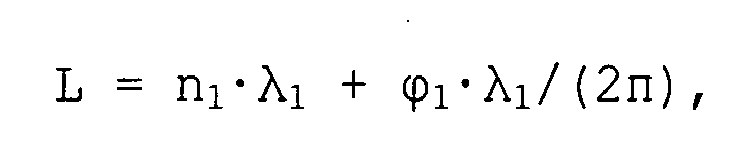
wherein n1 is the number of the complete first wavelengths λ1 within the distance L and ϕ1 is the phase of the first ultrasound wave at theultrasound receiver 12 relative to the first ultrasound wave at theultrasound transmitter 10. - In a similar way, the relationship between the distance L and the second wavelength λ2 is given by

wherein n2 is the number of the complete second wavelengths λ2 within the distance L and ϕ2 is the phase of the second ultrasound wave at theultrasound receiver 12 relative to the second ultrasound wave at theultrasound transmitter 10. - The first frequency f1 and the second frequency f2 may be generated by a common frequency generator with a given clock frequency fc. The first frequency f1 and the second frequency f2 are obtained by division of the clock frequency fc by a divisor N1 and N2, respectively:

- The resulting velocity of the ultrasound waves is given by

wherein the frequency difference
must be positive and the side condition
must be satisfied. If said side condition is satisfied, then the phases ϕ1 and ϕ2 are never equal to each other. Thus, the value of Δϕ is always positive. Thereby L is the distance between theultrasound transmitter 10 and theultrasound receiver 12, ΔL is the variation range of L, Δϕ is the phase difference, Vmin is the minimal possible velocity of the ultrasound waves and Δ(Δf) is the variation range of the frequency difference Δf. - If ϕ1 ≥ ϕ2, then the phase difference Δϕ is given by Δϕ = ϕ1 - ϕ2. Else, if ϕ1 < ϕ2, then the phase difference Δϕ s given by Δϕ = ϕ1 - ϕ2 + 2n. The variation range Δ(Δf) of the frequency difference Δf is given by

wherein δfc is the relative error of the clock frequency fc. - The minimal possible velocity Vmin of the ultrasound waves is Vmin = 331.244 m/s for dry air at a temperature of T = 0°C and a pressure of P = 1 atm.
- By using realistic values, i.e. fc = 20 MHz, δfc = 0.5%, ΔL = 3 mm, N1 = 497 and N2 = 503, the distance L between the
ultrasound transmitter 10 and theultrasound receiver 12 must be L < 684 mm. - The velocity of the ultrasound waves depends on temperature and humidity by the expression:

wherein T is the temperature, MA is the molar mass of dry air, MV is the molar mass of water vapour, R is the molar ideal gas constant and Z is the compressibility factor. The numerical values of the constants are given by


- The compressibility factor Z depends on the temperature T, the molar fraction XV and the pressure P. However, in this case the compressibility factor Z is about one.
- The molar fraction XV of water vapour in the air is determined by the specific humidity SH

- The specific humidity SH is defined by

wherein mV is the weight of the water vapour part and mA is the weight of the dry air part. Said water vapour part and said dry air part form a real air-vapour mixture filling the same volume. - For realistic accuracies ΔV ± 6.27 m/s, ΔT ± 5°C and ΔP ± 300 mm/Hg, in the worst case the absolute error of the specific humidity is ΔSH ± 9%.
- If the specific humidity SH, the temperature T and the pressure P are known, then the relative humidity can be calculated

wherein PVS(T) is the saturation vapour pressure of water at a given temperature T. -
FIG 3 illustrates a schematic diagram of a perspective front view of the inner space of anoven cavity 14 according to a first embodiment of the present invention. Theoven cavity 14 is bordered by atop wall 16, abottom wall 18, aleft side wall 20, aright side wall 22 and arear wall 24. Therear wall 24 includes afan 26 comprising apropeller 28. - A number of
side grids 30 are pair-wise arranged on the inner sides of theside walls side grids 30 of each pair are arranged at the same level. Theside grids 30 extend horizontally along the inner sides of theside walls side grids 30 is provided to support a tray or a grid. - In this embodiment the
ultrasound transmitter 10 is arranged in a front portion of theleft side wall 20. Theultrasound transmitter 10 is arranged between the twolowest side grids 30. In a similar way theultrasound receiver 12 is arranged in a front portion of theright side wall 22 between the twolowest side grids 30, so that theultrasound transmitter 10 and theultrasound receiver 12 are ordered symmetrically. - The
ultrasound transmitter 10 and theultrasound receiver 12 are located in such positions, that the space between them is free from any matter. Thus, the propagation of the ultrasound waves from theultrasound transmitter 10 and to theultrasound receiver 12 is undisturbed. There is a direct geometric connection between theultrasound transmitter 10 and theultrasound receiver 12. - The distance L between the
ultrasound transmitter 10 and theultrasound receiver 12 is equal to the inner width of theoven cavity 14. A typical value of the inner width of theoven cavity 14 is L = 440 mm. Said typical inner width of L = 440 mm fortunately satisfies the above side condition L < 684 mm. -
FIG 4 illustrates a schematic diagram of a perspective front view of the inner space of theoven cavity 14 according to a second embodiment of the present invention. Theoven cavity 14 is bordered by thetop wall 16, thebottom wall 18, theleft side wall 20, theright side wall 22 and therear wall 24. Therear wall 24 includes thefan 26 with thepropeller 28. - The number of
side grids 30 is pair-wise arranged on the inner sides of theside walls side grids 30 of each pair are arranged at the same level. Theside grids 30 extend horizontally along the inner sides of theside walls side grids 30 is provided to support the tray or the grid. - In this embodiment the
ultrasound transmitter 10 is arranged in a rear portion of theleft side wall 20. Theultrasound transmitter 10 is arranged between the twoupper side grids 30. In a similar way theultrasound receiver 12 is arranged in a rear portion of theright side wall 22 between the twoupper side grids 30, so that theultrasound transmitter 10 and theultrasound receiver 12 are ordered symmetrically. - Also in this embodiment the
ultrasound transmitter 10 and theultrasound receiver 12 are located in such positions, that the space between them is free from any matter. Thus, the propagation of the ultrasound waves from theultrasound transmitter 10 and to theultrasound receiver 12 is undisturbed. There is also a direct geometric connection between theultrasound transmitter 10 and theultrasound receiver 12. - A
temperature sensor 32 is arranged at therear wall 24. Saidtemperature sensor 32 is located in the region between theultrasound transmitter 10 and theultrasound receiver 12. Thus, the temperature can be detected in the same region, where the velocity of the ultrasound is estimated. Since the calculation of the humidity bases on the actual value of the temperature, the arrangement contributes to the accuracy of the calculation of the humidity. - Also in this embodiment the distance L between the
ultrasound transmitter 10 and theultrasound receiver 12 is equal to the inner width of theoven cavity 14. The typical value is L = 440 mm, which fortunately satisfies the above side condition of L < 684 mm. -
FIG 5 illustrates a schematic diagram of the velocity V of the ultrasound waves as a function of the specific humidity SH according to the preferred embodiment of the present invention. - The diagram shows twelve functions for three different pressures P = 0.5 atm, P = 1.0 atm and P = 1.5 atm and four different temperatures T = 100°C, T = 200°C, T = 300°C and T = 400°C. The pressure P = 0.5 atm is represented by dotted lines, the pressure P = 1.0 atm by solid lines and the pressure P = 1.5 atm by dashed lines.
- The velocity of the ultrasound wave increases marginally with a decreasing pressure for high humidity values. Further, the velocity of the ultrasound wave increases clearly with an increasing temperature for all humidity values.
- With the function in
FIG 5 the humidity SH can be estimated accurately by the knowledge of the velocity V of the ultrasound waves and the temperature T within the oven cavity. - The accuracy for estimating the humidity can be improved by calibration on the basis of the above mentioned theoretical expressions. The calibration should be performed in the whole range of humidity between 0% and 100% for all possible temperatures up to 350°C inside the oven. In particular, the calibration is advantageous, if the ultrasound waves do not form a narrow beam, so that the ultrasound waves may be reflected at the
inner walls oven cavity 14. Then theultrasound receiver 12 will receive the direct ultrasound waves from theultrasound transmitter 10 as well as the reflected ultrasound waves. The reflected ultrasound waves may cause an error in the estimation of the velocity of the ultrasound waves. Said error may be compensated by the above calibration. - The present invention allows the estimation of the average humidity among the whole cavity, but not any localized humidity around a sensor. The present invention allows a very fast estimation of the humidity. Several repeated measurements and a subsequent calculation of an average value can improve the accuracy.
-
Appropriate ultrasound transmitters 10 andultrasound receivers 12 with sufficient temperature and chemical resistance are available. - The
ultrasound transmitter 10 and theultrasound receiver 12 can be used for other purposes. For example, an open oven door may be detected. Further, it can be detected, if theoven cavity 14 is loaded or not. - The present invention can also be embedded in a computer program product, which comprises all the features enabling the implementation of the method described herein. Further, when loaded in a computer system, said computer program product is able to carry out these methods.
- Although illustrative embodiments of the present invention have been described herein with reference to the accompanying drawing, it is to be understood that the present invention is not limited to those precise embodiments, and that various other changes and modifications may be affected therein by one skilled in the art without departing from the scope or spirit of the invention. All such changes and modifications are intended to be included within the scope of the invention as defined by the appended claims.
-
- 10
- ultrasound transmitter
- 12
- ultrasound receiver
- 14
- oven cavity
- 16
- top wall
- 18
- bottom wall
- 20
- left side wall
- 22
- right side wall
- 24
- rear wall
- 26
- fan
- 28
- propeller
- 30
- side grid
- 32
- temperature sensor
- f0
- resonance frequency
- f1
- first frequency
- f2
- second frequency
- fc
- clock frequency
- N1
- divisor of the first frequency f1
- N2
- divisor of the second frequency f2
- Δf
- difference frequency between f1 and f2
- Δ(Δf)
- variation of the difference frequency Δf
- λ1
- first wavelength
- λ2
- second wavelength
- L
- distance between
transmitter 10 andreceiver 12 - ΔL
- variation of the distance L
- n1
- number of complete first wavelengths λ1
- n2
- number of complete second wavelengths λ2
Claims (15)
- An apparatus for estimating the air humidity within an oven cavity (14) by using ultrasound waves with at least two different frequencies (f1, f2), wherein said apparatus comprises:- at least one ultrasound transmitter (10) for generating the ultrasound waves,- at least one ultrasound receiver (12) for receiving the ultrasound waves,- at least one phase detecting device for detecting the phase (ϕ1, ϕ2) of the ultrasound wave at the ultrasound receiver (12) relative to the same ultrasound wave with the same frequency (f1, f2) at the ultrasound transmitter (10),- at least one evaluation unit for calculating the velocity (V) of the ultrasound waves on the basis of the phases (ϕ1, ϕ2) and frequencies (f1, f2) of the ultrasound waves with the two different frequencies (f1, f2),- at least one temperature sensor (32) for detecting the temperature (T) in the oven cavity (14), and- at least one estimation unit for estimating the humidity in the oven cavity (14) on the basis of the temperature (T) in the oven cavity (14) and the velocity (V) of the ultrasound waves.
- The apparatus according to claim 1,
characterized in, that
the ultrasound transmitter (10) and/or the ultrasound receiver (12) are arranged at or within opposite walls (20, 22) of the oven cavity (14). - The apparatus according to claim 1 or 2,
characterized in, that
the ultrasound transmitter (10) and/or the ultrasound receiver (12) are arranged in front or rear portions of side walls (20, 22) of the oven cavity (14). - The apparatus according to any one of the preceding claims,
characterized in, that
the temperature sensor (32) is arranged between the ultrasound transmitter (10) and the ultrasound receiver (12). - The apparatus according to any one of the preceding claims,
characterized in, that
the evaluation unit is provided for calculating the velocity (V) on the basis of the distance (L) between the ultrasound transmitter (10) and the ultrasound receiver (12) . - The apparatus according to any one of the preceding claims,
characterized in, that
the apparatus is provided for an electric oven. - A method for estimating the air humidity within an oven cavity, wherein said method comprises the steps of:- generating ultrasound waves with at least two different frequencies (f1, f2),- receiving the ultrasound waves with the at least two different frequencies (f1, f2),- detecting the phase (ϕ1) of the ultrasound wave with a first frequency (f1) at the ultrasound receiver (12) relative to the same ultrasound wave with the first frequency (f1) at the ultrasound transmitter (10),- detecting the phase (ϕ2) of the ultrasound wave with a second frequency (f2) at the ultrasound receiver (12) relative to the same ultrasound wave with the second frequency (f2) at the ultrasound transmitter (10),- calculating the velocity (V) of the ultrasound waves on the basis of the phases (ϕ1, ϕ2) and frequencies (f1, f2) of the ultrasound waves with the two different frequencies (f1, f2),- detecting the temperature (T) within the oven cavity (14), and- estimating the humidity in the oven cavity (14) on the basis of the temperature (T) and the velocity (V) of the ultrasound waves.
- The method according to claim 7,
characterized in, that
a first frequency (f1) is marginally bigger and a second frequency (f2) is marginally smaller than a resonance frequency (f0) of an ultrasound transducer formed by the ultrasound transmitter (10) and the ultrasound receiver (12). - The method according to claim 7 or 8,
characterized in, that
the velocity (V) of the ultrasound waves is estimated by the distance (L) between the ultrasound transmitter (10) and the ultrasound receiver (12). - The method according to any one of the claims 7 to 9,
characterized in, that
the velocity (V) of the ultrasound waves is estimated by V=[2π·L·(f1-f2)]/Δϕ, wherein Δϕ=ϕ1-ϕ2, if ϕ1>ϕ2, and Δϕ=ϕ1-ϕ2+2π, if ϕ1<ϕ2, and wherein f1 is the first frequency, f2 is the second frequency, ϕ1 is the phase corresponding with the first frequency f1, ϕ2 is the phase corresponding with the second frequency f2 and L is the distance between the ultrasound transmitter (10) and the ultrasound receiver (12). - The method according to any one of the claims 7 to 10,
characterized in, that
the temperature (T) is detected within a space between the ultrasound transmitter (10) and the ultrasound receiver (12). - The method according to any one of the claims 7 to 11,
characterized in, that
the frequencies (f1, f2) are generated by dividing a predetermined clock frequency (fC). - The method according to any one of the claims 7 to 12,
characterized in, that the frequencies (f1, f2) are generated by a common generator. - The method according to any one of the claims 7 to 13,
characterized in, that
the estimated humidity is used for a cooking program in order to optimize the cooking process. - A computer program product stored on a computer usable medium, comprising computer readable program means for causing a computer to realize a method according to any one of the preceding claims 7 to 14.
Priority Applications (7)
| Application Number | Priority Date | Filing Date | Title |
|---|---|---|---|
| EP09002306A EP2221613A1 (en) | 2009-02-19 | 2009-02-19 | An apparatus and a method for estimating the air humidity within an oven cavity |
| US13/147,435 US8652552B2 (en) | 2009-02-19 | 2010-02-18 | Apparatus and a method for estimating the air humidity within an oven cavity |
| AU2010214844A AU2010214844C1 (en) | 2009-02-19 | 2010-02-18 | An apparatus and a method for estimating the air humidity within an oven cavity |
| PCT/EP2010/001004 WO2010094473A1 (en) | 2009-02-19 | 2010-02-18 | An apparatus and a method for estimating the air humidity within an oven cavity |
| EP10705551A EP2399122A1 (en) | 2009-02-19 | 2010-02-18 | An apparatus and a method for estimating the air humidity within an oven cavity |
| CA2752627A CA2752627A1 (en) | 2009-02-19 | 2010-02-18 | An apparatus and a method for estimating the air humidity within an oven cavity |
| CN201080007827.5A CN102317769B (en) | 2009-02-19 | 2010-02-18 | An apparatus and a method for estimating the air humidity within an oven cavity |
Applications Claiming Priority (1)
| Application Number | Priority Date | Filing Date | Title |
|---|---|---|---|
| EP09002306A EP2221613A1 (en) | 2009-02-19 | 2009-02-19 | An apparatus and a method for estimating the air humidity within an oven cavity |
Publications (1)
| Publication Number | Publication Date |
|---|---|
| EP2221613A1 true EP2221613A1 (en) | 2010-08-25 |
Family
ID=40811198
Family Applications (2)
| Application Number | Title | Priority Date | Filing Date |
|---|---|---|---|
| EP09002306A Withdrawn EP2221613A1 (en) | 2009-02-19 | 2009-02-19 | An apparatus and a method for estimating the air humidity within an oven cavity |
| EP10705551A Withdrawn EP2399122A1 (en) | 2009-02-19 | 2010-02-18 | An apparatus and a method for estimating the air humidity within an oven cavity |
Family Applications After (1)
| Application Number | Title | Priority Date | Filing Date |
|---|---|---|---|
| EP10705551A Withdrawn EP2399122A1 (en) | 2009-02-19 | 2010-02-18 | An apparatus and a method for estimating the air humidity within an oven cavity |
Country Status (6)
| Country | Link |
|---|---|
| US (1) | US8652552B2 (en) |
| EP (2) | EP2221613A1 (en) |
| CN (1) | CN102317769B (en) |
| AU (1) | AU2010214844C1 (en) |
| CA (1) | CA2752627A1 (en) |
| WO (1) | WO2010094473A1 (en) |
Cited By (1)
| Publication number | Priority date | Publication date | Assignee | Title |
|---|---|---|---|---|
| CN116725379A (en) * | 2023-07-26 | 2023-09-12 | 宁波方太厨具有限公司 | Cooking equipment, control method thereof and humidity detection device |
Families Citing this family (9)
| Publication number | Priority date | Publication date | Assignee | Title |
|---|---|---|---|---|
| DE102011016963A1 (en) * | 2011-04-13 | 2012-10-18 | Hydrometer Gmbh | Method for measuring flow rates on the principle of ultrasonic transit time difference |
| CN102980941B (en) * | 2012-11-26 | 2015-12-02 | 华南理工大学 | A kind of ultrasonic gas relative humidity detection method and device utilizing sonic velocity change |
| JP2016520839A (en) * | 2013-05-31 | 2016-07-14 | ネステク ソシエテ アノニム | System and method for detecting a water / product interface during food processing |
| US9919582B2 (en) | 2016-01-26 | 2018-03-20 | Ford Global Technologies, Llc | Humidity estimation |
| DE102016112683B4 (en) * | 2016-07-11 | 2025-08-21 | Rational Aktiengesellschaft | Method for determining the humidity within a cooking chamber of a cooking appliance and cooking appliance |
| KR102184733B1 (en) * | 2016-08-05 | 2020-12-01 | 한국전자기술연구원 | Ultrasonic Flow Meter and Method for Flow Speed Measuring |
| CN106370711A (en) * | 2016-08-29 | 2017-02-01 | 安徽华菱西厨装备股份有限公司 | Quick detection device and quick detection method for humidity of inner chamber of steam oven |
| CN109187738A (en) * | 2018-10-15 | 2019-01-11 | 江苏久创电气科技有限公司 | A kind of sulfur hexafluoride gas detection device based on ultrasonic wave principle |
| WO2021224954A1 (en) * | 2020-05-07 | 2021-11-11 | 三菱電機株式会社 | Humidity sensor and air conditioner |
Citations (4)
| Publication number | Priority date | Publication date | Assignee | Title |
|---|---|---|---|---|
| EP0174627B1 (en) | 1984-09-10 | 1993-06-23 | Sumitomo Bakelite Company Limited | Measuring instrument for concentration of gas |
| US5689060A (en) | 1992-03-06 | 1997-11-18 | Matsushita Electric Industrial Co., Ltd. | Humidity measuring device and a heat cooker employing the device |
| DE19841154A1 (en) * | 1998-09-09 | 2000-04-06 | Holger Loehmer | Measurement of propagation time of sound waves; involves measuring phase shift between transmitted and received signals at two different frequencies |
| DE10143841A1 (en) | 2001-09-06 | 2003-04-03 | Neubauer Kurt Maschf | A food cooking oven has moisture sensing means as well as temperature sensing to determine the process of the cooking. |
Family Cites Families (12)
| Publication number | Priority date | Publication date | Assignee | Title |
|---|---|---|---|---|
| FI54977C (en) * | 1978-02-10 | 1979-04-10 | Ilkka Markus Leino | MAINTENANCE FOR FUNCTIONAL OPERATING ACTIVITIES WITH ENTRY |
| US4876889A (en) * | 1988-07-05 | 1989-10-31 | Parthasarathy Shakkottai | Acoustic humidity sensor |
| US5365039A (en) * | 1992-07-21 | 1994-11-15 | Hatco Corporation | Humidity controlled food warmer |
| JPH06258298A (en) * | 1993-03-03 | 1994-09-16 | Matsushita Electric Ind Co Ltd | Humidity measuring device and cooking appliance using it |
| US6178827B1 (en) * | 1999-04-22 | 2001-01-30 | Murray F. Feller | Ultrasonic flow sensor |
| US6422093B2 (en) * | 1999-12-10 | 2002-07-23 | Murray Feller | Burst mode ultrasonic flow sensor |
| US6370963B1 (en) * | 2000-06-13 | 2002-04-16 | Murray F. Feller | Ultrasonic transit time flow sensor and method |
| US6575044B1 (en) * | 2002-05-06 | 2003-06-10 | Murray F. Feller | Transit-time flow sensor combining high resolution and wide dynamic range |
| CA2496396A1 (en) * | 2002-08-21 | 2004-03-04 | The University Of Manitoba | Ultrasonic evaluation of the strength of flour doughs |
| AT6511U3 (en) * | 2003-07-16 | 2004-09-27 | Avl List Gmbh | ULTRASONIC GAS FLOW SENSOR AND DEVICE FOR MEASURING EXHAUST GAS FLOWS FROM COMBUSTION ENGINES AND A METHOD FOR DETERMINING THE FLOW OF GASES |
| CN100365432C (en) * | 2005-10-11 | 2008-01-30 | 汪柏年 | Method and device for measuring displacement/distance based on supersonic wave or sonic continuous sound-field phase-demodulating principle |
| DE102005051669B3 (en) * | 2005-10-28 | 2007-04-26 | Mib Gmbh Messtechnik Und Industrieberatung | Flow measurement method |
-
2009
- 2009-02-19 EP EP09002306A patent/EP2221613A1/en not_active Withdrawn
-
2010
- 2010-02-18 US US13/147,435 patent/US8652552B2/en not_active Expired - Fee Related
- 2010-02-18 AU AU2010214844A patent/AU2010214844C1/en not_active Ceased
- 2010-02-18 CN CN201080007827.5A patent/CN102317769B/en not_active Expired - Fee Related
- 2010-02-18 WO PCT/EP2010/001004 patent/WO2010094473A1/en not_active Ceased
- 2010-02-18 CA CA2752627A patent/CA2752627A1/en not_active Abandoned
- 2010-02-18 EP EP10705551A patent/EP2399122A1/en not_active Withdrawn
Patent Citations (4)
| Publication number | Priority date | Publication date | Assignee | Title |
|---|---|---|---|---|
| EP0174627B1 (en) | 1984-09-10 | 1993-06-23 | Sumitomo Bakelite Company Limited | Measuring instrument for concentration of gas |
| US5689060A (en) | 1992-03-06 | 1997-11-18 | Matsushita Electric Industrial Co., Ltd. | Humidity measuring device and a heat cooker employing the device |
| DE19841154A1 (en) * | 1998-09-09 | 2000-04-06 | Holger Loehmer | Measurement of propagation time of sound waves; involves measuring phase shift between transmitted and received signals at two different frequencies |
| DE10143841A1 (en) | 2001-09-06 | 2003-04-03 | Neubauer Kurt Maschf | A food cooking oven has moisture sensing means as well as temperature sensing to determine the process of the cooking. |
Cited By (1)
| Publication number | Priority date | Publication date | Assignee | Title |
|---|---|---|---|---|
| CN116725379A (en) * | 2023-07-26 | 2023-09-12 | 宁波方太厨具有限公司 | Cooking equipment, control method thereof and humidity detection device |
Also Published As
| Publication number | Publication date |
|---|---|
| US20120225179A1 (en) | 2012-09-06 |
| CN102317769A (en) | 2012-01-11 |
| AU2010214844A1 (en) | 2011-07-28 |
| CA2752627A1 (en) | 2010-08-26 |
| AU2010214844B2 (en) | 2014-11-13 |
| EP2399122A1 (en) | 2011-12-28 |
| US8652552B2 (en) | 2014-02-18 |
| CN102317769B (en) | 2014-08-06 |
| WO2010094473A1 (en) | 2010-08-26 |
| AU2010214844C1 (en) | 2015-04-16 |
Similar Documents
| Publication | Publication Date | Title |
|---|---|---|
| US8652552B2 (en) | Apparatus and a method for estimating the air humidity within an oven cavity | |
| Huang et al. | Multiple-frequency ultrasonic distance measurement using direct digital frequency synthesizers | |
| AU2015235436B2 (en) | Method for measuring internal temperature of object to be frozen and device for measuring internal temperature of object to be frozen | |
| JP5163857B2 (en) | Concrete structure quality inspection method and concrete structure quality inspection apparatus | |
| JP5932746B2 (en) | Media boundary position measurement system | |
| JP6909697B2 (en) | Propagation time measuring device, gas concentration measuring device, and propagation time measuring program | |
| US7098645B1 (en) | Method and device for cable length measurement based on reflected phase shifts | |
| EP3822613B1 (en) | Measurement system for determining liquid properties in a vessel | |
| KR20240107126A (en) | Waveform shaping device and gas concentration measuring device | |
| JP3877591B2 (en) | Packing detection method and apparatus | |
| JP6472566B1 (en) | Composition ratio estimation device, composition ratio estimation method, composition ratio estimation program, and liquid level gauge | |
| KR20240095426A (en) | gas concentration measuring device | |
| HK1161641A (en) | An apparatus and a method for estimating the air humidity within an oven cavity | |
| JP2009109296A (en) | Ultrasonic liquid level meter | |
| JP2019066423A (en) | Ultrasonic transmitter, propagation time measuring device, gas concentration measuring device and propagation time measuring program | |
| JP2008309779A (en) | Relative permittivity / conductivity measuring apparatus and measuring method thereof | |
| Hart et al. | Optical measurement of the speed of sound in air over the temperature range 300–650 K | |
| Barrera-Figueroa et al. | On experimental determination of the free-field correction of laboratory standard microphones at normal incidence | |
| RU2350899C1 (en) | Method for detection of dielectric coat thickness | |
| JP2002062198A (en) | Acoustic gas temperature measurement method and acoustic gas thermometer | |
| US9958309B2 (en) | Method for measuring level of material level measuring apparatus | |
| US20150027230A1 (en) | Pressure measuring device | |
| JP2010217046A (en) | Method and device for measurement of temperature using ultrasonic wave | |
| Schulthes | A new technique to determine the complex modulus in accordance with ISO 6721 | |
| JP2007121199A (en) | Density measuring apparatus and density measuring method |
Legal Events
| Date | Code | Title | Description |
|---|---|---|---|
| PUAI | Public reference made under article 153(3) epc to a published international application that has entered the european phase |
Free format text: ORIGINAL CODE: 0009012 |
|
| 17P | Request for examination filed |
Effective date: 20090812 |
|
| AK | Designated contracting states |
Kind code of ref document: A1 Designated state(s): AT BE BG CH CY CZ DE DK EE ES FI FR GB GR HR HU IE IS IT LI LT LU LV MC MK MT NL NO PL PT RO SE SI SK TR |
|
| AX | Request for extension of the european patent |
Extension state: AL BA RS |
|
| RAP1 | Party data changed (applicant data changed or rights of an application transferred) |
Owner name: ELECTROLUX HOME PRODUCTS CORPORATION N.V. |
|
| AKX | Designation fees paid |
Designated state(s): AT BE BG CH CY CZ DE DK EE ES FI FR GB GR HR HU IE IS IT LI LT LU LV MC MK MT NL NO PL PT RO SE SI SK TR |
|
| RAP1 | Party data changed (applicant data changed or rights of an application transferred) |
Owner name: ELECTROLUX HOME PRODUCTS CORPORATION N.V. |
|
| GRAP | Despatch of communication of intention to grant a patent |
Free format text: ORIGINAL CODE: EPIDOSNIGR1 |
|
| RIC1 | Information provided on ipc code assigned before grant |
Ipc: G01N 29/34 20060101AFI20151214BHEP Ipc: G01N 29/024 20060101ALI20151214BHEP |
|
| INTG | Intention to grant announced |
Effective date: 20160108 |
|
| STAA | Information on the status of an ep patent application or granted ep patent |
Free format text: STATUS: THE APPLICATION IS DEEMED TO BE WITHDRAWN |
|
| 18D | Application deemed to be withdrawn |
Effective date: 20160519 |