EP2221514B1 - Method of manufacture of compliant plate seals - Google Patents
Method of manufacture of compliant plate seals Download PDFInfo
- Publication number
- EP2221514B1 EP2221514B1 EP10153023.6A EP10153023A EP2221514B1 EP 2221514 B1 EP2221514 B1 EP 2221514B1 EP 10153023 A EP10153023 A EP 10153023A EP 2221514 B1 EP2221514 B1 EP 2221514B1
- Authority
- EP
- European Patent Office
- Prior art keywords
- shims
- top plate
- shim pack
- plate
- spacer
- Prior art date
- Legal status (The legal status is an assumption and is not a legal conclusion. Google has not performed a legal analysis and makes no representation as to the accuracy of the status listed.)
- Not-in-force
Links
Images


Classifications
-
- F—MECHANICAL ENGINEERING; LIGHTING; HEATING; WEAPONS; BLASTING
- F16—ENGINEERING ELEMENTS AND UNITS; GENERAL MEASURES FOR PRODUCING AND MAINTAINING EFFECTIVE FUNCTIONING OF MACHINES OR INSTALLATIONS; THERMAL INSULATION IN GENERAL
- F16J—PISTONS; CYLINDERS; SEALINGS
- F16J15/00—Sealings
- F16J15/16—Sealings between relatively-moving surfaces
- F16J15/32—Sealings between relatively-moving surfaces with elastic sealings, e.g. O-rings
- F16J15/3284—Sealings between relatively-moving surfaces with elastic sealings, e.g. O-rings characterised by their structure; Selection of materials
- F16J15/3292—Lamellar structures
-
- Y—GENERAL TAGGING OF NEW TECHNOLOGICAL DEVELOPMENTS; GENERAL TAGGING OF CROSS-SECTIONAL TECHNOLOGIES SPANNING OVER SEVERAL SECTIONS OF THE IPC; TECHNICAL SUBJECTS COVERED BY FORMER USPC CROSS-REFERENCE ART COLLECTIONS [XRACs] AND DIGESTS
- Y10—TECHNICAL SUBJECTS COVERED BY FORMER USPC
- Y10T—TECHNICAL SUBJECTS COVERED BY FORMER US CLASSIFICATION
- Y10T29/00—Metal working
- Y10T29/49—Method of mechanical manufacture
- Y10T29/49229—Prime mover or fluid pump making
- Y10T29/49297—Seal or packing making
-
- Y—GENERAL TAGGING OF NEW TECHNOLOGICAL DEVELOPMENTS; GENERAL TAGGING OF CROSS-SECTIONAL TECHNOLOGIES SPANNING OVER SEVERAL SECTIONS OF THE IPC; TECHNICAL SUBJECTS COVERED BY FORMER USPC CROSS-REFERENCE ART COLLECTIONS [XRACs] AND DIGESTS
- Y10—TECHNICAL SUBJECTS COVERED BY FORMER USPC
- Y10T—TECHNICAL SUBJECTS COVERED BY FORMER US CLASSIFICATION
- Y10T29/00—Metal working
- Y10T29/49—Method of mechanical manufacture
- Y10T29/49718—Repairing
- Y10T29/49719—Seal or element thereof
-
- Y—GENERAL TAGGING OF NEW TECHNOLOGICAL DEVELOPMENTS; GENERAL TAGGING OF CROSS-SECTIONAL TECHNOLOGIES SPANNING OVER SEVERAL SECTIONS OF THE IPC; TECHNICAL SUBJECTS COVERED BY FORMER USPC CROSS-REFERENCE ART COLLECTIONS [XRACs] AND DIGESTS
- Y10—TECHNICAL SUBJECTS COVERED BY FORMER USPC
- Y10T—TECHNICAL SUBJECTS COVERED BY FORMER US CLASSIFICATION
- Y10T29/00—Metal working
- Y10T29/49—Method of mechanical manufacture
- Y10T29/49718—Repairing
- Y10T29/49721—Repairing with disassembling
- Y10T29/49723—Repairing with disassembling including reconditioning of part
- Y10T29/49725—Repairing with disassembling including reconditioning of part by shaping
- Y10T29/49726—Removing material
- Y10T29/49728—Removing material and by a metallurgical operation, e.g., welding, diffusion bonding, casting
-
- Y—GENERAL TAGGING OF NEW TECHNOLOGICAL DEVELOPMENTS; GENERAL TAGGING OF CROSS-SECTIONAL TECHNOLOGIES SPANNING OVER SEVERAL SECTIONS OF THE IPC; TECHNICAL SUBJECTS COVERED BY FORMER USPC CROSS-REFERENCE ART COLLECTIONS [XRACs] AND DIGESTS
- Y10—TECHNICAL SUBJECTS COVERED BY FORMER USPC
- Y10T—TECHNICAL SUBJECTS COVERED BY FORMER US CLASSIFICATION
- Y10T29/00—Metal working
- Y10T29/49—Method of mechanical manufacture
- Y10T29/49826—Assembling or joining
- Y10T29/49895—Associating parts by use of aligning means [e.g., use of a drift pin or a "fixture"]
Definitions
- the subject matter disclosed herein relates to a sealing structure between a rotating component and a static component and, more particularly, to a compliant plate seal arrangement manufacturing method.
- Dynamic sealing between a rotor (e.g., rotating shaft) and a stator (e.g., static shell or casing) is an important concern in turbomachinery.
- a rotor e.g., rotating shaft
- stator e.g., static shell or casing
- seal members such as compliant plate seals.
- Known brush seals include tightly-packed, generally cylindrical bristles that are arranged in a staggered arrangement to reduce leakage.
- the bristles have a low radial stiffness that allows them to move in the event of a rotor excursion while maintaining a tight clearance during steady state operations.
- Brush seals are generally effective only below a limited pressure differential across the seal. Because of the generally cylindrical geometry of the bristles, the brush seals tend to have a low stiffness in the axial direction, which limits the maximum operable pressure differential in known brush seals to generally less than 400 psi.
- Compliant plate seals have plate-like elements that have a significantly higher axial stiffness for a comparable radial stiffness and therefore such seals have the capability of being used with larger pressure differentials than known brush seals.
- Compliant plate seals often including thin plate like elements assembled together as a pack, are welded to a housing that supports the plates relative to a rotor (e.g., a rotating shaft).
- a rotor e.g., a rotating shaft.
- One method of joining is by welding.
- the joined region of the compliant members can shrink which causes distortion and wrinkling of the compliant plate elements, which can affect the radial stiffness of and the force distribution on the compliant plates, which can lead to several problems including increased axial leakage and rotor heating.
- US 2008/169614 describes a shaft seal assembly between a rotating shaft and a static shell, the shaft seal assembly including a seal housing in mechanical contact with the static shell, at least two rigid members of the seal housing, and a plurality of compliant plate members defining a sealing ring between the static shell and the rotating shaft.
- the plurality of compliant plate members is disposed between the at least two rigid members and retained within the seal housing by a compressive force between the at least two rigid members.
- US 2008/169614 discloses a compliant plate seal manufacturing method, comprising: assembling a plurality of t-shims and a plurality of spacer shims packed into a weld fixture at a prescribed angle, thereby forming a shim pack having a front and rear end and sides; welding the sides of the shim pack; removing a portion of the weld fixture [implicit from welding method]; removing the plurality of spacer shims; and shaping the shim pack into a target diameter" the shim pack includes a radial cutout region.
- a seal assembly comprising: a top plate; a shim pack welded to the top plate, wherein the shim pack includes alternately arranged t-shims and spacer shims at an angle to the top plate in which a lower portion of the spacer shims have been removed; and a radial flow plate coupled to the top plate; wherein the top plate and
- a compliant plate seal manufacturing method a compliant plate seal assembly manufactured according to the method and a weld fixture assembly configured to accommodate the compliant plate seal assembly during manufacture according to the method.
- Exemplary embodiments include a compliant seal manufacturing method that reduces distortion, deformity, differential shrinkage and other associated problems with welding across gaps between compliant plate seals as is typical in current manufacturing processes.
- compliant plate seals are joined in a straight form and then later bent to a diameter suitable for use in sealing opposite a rotor.
- alternating spacer shims and T-shims are stacked in a straight fixture against angle blocks and compressed to eliminate any gaps.
- the spacer shims include a pocket that permits a later machining operation that removes a lower portion of the spacer. A top edge of the compressed shim pack is aligned against a top plate.
- a top flat surface of the shim pack is welded to the bottom surface of the top plate implementing a deep narrow electron beam or laser weld. A weld is performed on each side of the top plate.
- the left and right sides of the upper welded shim pack are machined to allow the lower portion of the spacer shims to be removed. After removal of the lower portion of the spacer shims, the top surface and the bottom left and right faces of the top plate are used to bend the seal into an arcuate segment of some prescribed diameter suitable for the final application in a turbomachine. After the bend, a center portion of the top plate is removed to permit assembly of a machined arcuate housing with a radial flow restrictor plate.
- the top housing is mechanically assembled or welded to the T-plate pack.
- the tips of the T-shims are machined to a final rotor diameter.
- the left and right sides of the assembly are machined off at an angle coplanar to the T-shim pack and at the required sealing segment chord length. There can be several segments per 360-degree seal.
- T-shims can be fully joined to the top plate by welding with a metallurgical bond, using a method of fixturing, which packs the shims very tightly. Therefore, when welded, the impact of weld shrinkage causing T-plate distortion is minimized. T-plate spacing is held very accurate with this method. This method also minimizes T-shim stress and leakage. Joining the leaves in a straight configuration minimizes costs associated with custom weld fixturing for each seal diameter. Seals of any diameter can be bent from the straight stock. An appropriate size spacer shim is chosen for the range of diameters being bent. The straight fixture allows precise axial positioning of thousands of shims to within several tenths of a mil or less.
- Accurate and repeatable spacing between compliant members is important to achieving minimum compliant plate stress during operation as well as minimized seal leakage.
- a straight method of stacking with alternating spacer shim and T-shims lends itself to a machine-based automated shim stack process, further reducing hand or manual stacking operations for assembling shims. This is a cost and cycle advantage over arcuate housings, which are assembled more manually.
- the improved compliant plate seal manufacturing method described herein provides a structure that prevents distortion, deformity, differential shrinkage and other associated problems with welding across gaps between compliant plate seals.
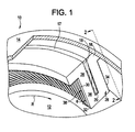
- FIG. 1 is a perspective view of an exemplary compliant plate seal assembly 10 as manufactured in accordance with exemplary embodiments described herein.
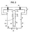
- FIG. 2 is a cross-sectional view of seal assembly 10 taken along line 2-2. More specifically, in FIG. 2 , seal assembly 10 is illustrated in a radially outward or retracted position, as described herein.
- FIG. 6 is a cross-sectional view of seal assembly 10 shown in FIG. 2 , with the presence of a rotor 12.
- the compliant plate seal assembly 10 facilitates reducing axial leakage between rotor 12, such as a rotating shaft, and the housing 14. More specifically, the housing 14 is coupled to a turbine static shell or stator such that rotor 12 rotates relative to housing 14. In exemplary embodiments, the housing 14 may be coupled within the stator.
- FIG. 2 illustrates set screws 40 as coupling the housing 14 to the joined complaints plate members 16.
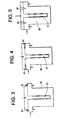
- FIGS. 3-5 illustrate alternate housing configurations and welds 41 as coupling the housing configurations to the compliant plate members. It is appreciated that any suitable housing configuration, coupling technique, and fastening technique can be implemented, which enables seal assembly 10 to function as described herein.
- the shaft seal assembly 10 is provided with a plurality of compliant plate elements 16 secured at their roots 26, in a facing relation (i.e., face-to-face).
- facing relation refers an orientation in which a first side surface 28 of one compliant plate element 16 is adjacent to a second side surface 30 of an immediate adjacent compliant plate element 16.
- Each side surface 28 and 30 extends from a leading surface 32 at a high pressure side 33 to a trailing surface 34 at a low pressure side 35 of each compliant plate element, and from a root 26 to a tip 36 of each compliant plate element 16. It is appreciated that the leading surfaces 32 and/or trailing surfaces 34 of elements 16 may be exposed at high pressure side 33 and/or low pressure side 35, respectively.
- each compliant plate element 16 is substantially planar, or flat, along each side surface 28 and 30.
- a gap 38 is defined between adjacent compliant plate elements 16 such that gap 38 is wider at an outer portion 42 than at an inner portion 44.
- the gap is pre-defined accordingly by the presence of spacer shims (not shown) alternately positioned between adjacent compliant plate elements 16 and selectively removed. Accordingly, gap 38 tapers from outer portion 42 towards inner portion 44.
- roots 26 of plate members 16 may be considered to be “loosely packed,” and tips 36 may be considered to be “tightly packed.”
- the term “tightly packed,” as used herein, refers to an orientation in which adjacent plate tips 36 are not in contact with each other but are closely spaced.
- the compliant plate elements 16 are coupled to housing 14 such that each plate element 16 is oriented at an angle ⁇ (also referred to herein as a "cant angle") relative to a respective tangent plane 48 of rotor 12.
- the tangent plane 48 is defmed at a line 50 on rotor 12 that is proximate to plate tip 36. More specifically, at least one of the side surfaces 28 and/or 30 is oriented at angle ⁇ relative to tangent plane 48.
- the cant angle ⁇ is less than 90°.
- cant angle ⁇ is selected to be some specific prescribed value between approximately 20° and approximately 70°.
- the cant angle ⁇ is selected to ensure that plate elements 16 are angled away from a direction R of rotation of rotor 12 such that the cant angle ⁇ facilitates rotation of rotor 12 within seal assembly 10.
- an axial flow resistance member 17 extends at least partially through compliant plate elements 16 via a slot 20 and facilitates preventing axial leakage flow between gaps 38. More specifically, in the exemplary embodiment, resistance member 17 extends circumferentially about housing 14, and extends radially inward from housing 14 towards rotor 12.
- the slot 20 and the axial flow resistance member 17 has a substantially constant width W 1 , W 2 , respectively.
- the axial flow resistance member 17 can include an upper portion 18 having width W 3 , which can be substantially equal to the width W 1 of the slot 20.
- widths W 1 , W 2 , W 3 may be of any size that enables seal assembly 10 to function as described herein.
- a gap 58 is defined between the axial flow resistance member 17 and the slot 20.
- the gap 58 includes a front section 62, a bridge section 63, and a back section 64. In FIG.
- the slot 20 of compliant plate 16 and axial flow resistance member 17 of housing 14 are shown in the center of compliant plate member 16.
- the axial flow resistance member 17 and the slot 20 of the compliant plate may be offset in the axial direction from the center of housing 14.
- dimensions of the gap 58 are selected based on predetermined hydrostatic lift and/or hydrostatic blowdown conditions.
- the front section 62 may decrease while back section 64 increases.
- Such a gap configuration may cause hydrostatic blowdown.
- the term "blowdown" refers to a radially inward deflection of compliant plate elements 16 under a pressure loading.
- the front section 62 may be larger than back section 64.
- Such a gap configuration may cause lift on plate elements 16.
- the compliant plate elements 16 experience an effective blowdown force near front section 62 and an effective lift force near back section 64, wherein front and back sections 62 and 64 are closer to each other as compared to known compliant plate seal assemblies.
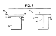
- FIG. 7 illustrates a spacer shim 70 and T-shim 75 prior to manufacturing into the seal assembly 10 in accordance with exemplary embodiments.
- alternating rows of spacer shims 70 and T-shims 75 are tightly packed as a first step in forming the compliant plate members 16.
- the spacer shim 70 is implemented to provide the required spacing between each of the T-shims 75 in the alternately packed arrangement.
- the spacer shims 70 include a cut out region 71 within an upper T-region 72 of the spacer shim.
- ears 73 of the upper T-region 72 are later machined off on the left and right and then a portion 74 of the spacer shim 70 below the cut out region 71 drops out of the seal assembly 10.
- Thickness of the spacer shim 70 can be selected as some thickness value generally within the range 0.0005" to 0.004" to define the gap 38.
- the T-shims 75 are the shims or plates that include the flexible part of the seal assembly and are a portion of the complaint plate member 16.
- a center cutout 76 later defines the slot 20 that includes the radially oriented axial flow resistance member 17.
- the T-shims 75 further includes an upper T-region 77 that includes ears 78 that are machined off later along with the ears 73 of the spacer shims 70.
- the thickness of the T-shim 75 is selected as some thickness value generally within the range .002" to .030" as labeled T in FIG. 6 . This manufacturing technique does not limit the spacer thickness and can work for any practical thickness larger or smaller than the specified range.
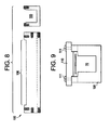
- FIGS. 8 & 9 illustrates a side and front view of a weld fixture body 100 into which the spacer shims 70 and the T-shims 75 are alternately packed along a straight line as described above.
- the spacer shims 70 and the T-shims 75 are alternately packed within a channel 105 defined within the fixture body 100.
- the weld fixture body further includes a cut-out region 106, which defines a window for welding as further described herein.
- FIG. 9 illustrates a front view of the weld fixture body 100 assembled with the alternately spaced spacer shims 70 and T-shims 75. A spacer shim 70 is shown.
- FIG. 9 further illustrates a top plate 110 mechanically affixed to the weld fixture body. In exemplary embodiments, bolts 111 mechanically affix the top plate 110 to the weld fixture body 100.
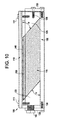
- FIG. 10 illustrates a side section view of an assembled weld fixture assembly 180.
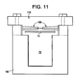
- FIG. 11 illustrates a front section view of the welded compliant plate seal still within the weld fixture assembly 180.
- the weld fixture assembly 180 includes the weld fixture body 100 and the top plate 110 as described above.
- the weld fixture assembly 180 further includes the alternating spacer shims 70 and T-shims, now referred to as the shim pack 115.
- Left and right angle blocks 120, 125 are inserted into the channel 105 of the weld fixture body 100 on opposite ends of the shim pack 115.
- the angle blocks 120, 125 establish a fixture block angle ⁇ of the shim pack 115 with respect to the top plate 110.
- the fixture block angle ⁇ is selected to correspond with a desired angle of the shim pack 115 welded to the top plate 110.
- the angle ⁇ can be selected as 45 degrees.
- a left and right end plate 130, 135 are further mechanically affixed to the weld fixture body 100.
- the end plates 130, 135 can be mechanically affixed to the weld fixture body 100 via bolts 136.
- the end plates 130, 135 retain the angle blocks 120, 125 within the channel and against the shim pack 115.
- Loading screws 140 can be adjusted to push the end block and sliding it to compress the shim pack 115 to minimize any spaces in a weld region 145 of the shim pack 115.
- the weld region 145 of the shim pack 115 is exposed through the weld fixture body 100 through a window 150 defined between the top plate 110 and the cut out region 106 as described above.
- a weld beam is focused into the window 150 along the weld region 145 in order to weld the shim pack 115 to the top plate 110.
- the weld beam can be an electron beam, which provides a thin and narrow beam to minimize heating of the top plate 110 as well as a deep weld along the top plate 110 and shim pack 115.
- FIG. 11 illustrates welds 155 along the weld region 145 defined between the top plate 110 and the shim pack 115.
- the welds 155 runs to a depth that is past the cut out regions of both the spacer shims 70 and T-shims 75. In an alternate exemplary embodiment, the welds 155 do not extend past the cut out regions of the both the spacer shims 70 and T-shims 75.
- the end plates 130, 135 are removed from the weld fixture body 100.
- the angle blocks 120, 125 are also removed from the weld fixture body 100.
- the top plate 110 and the shim pack 115 are now welded together and are also removed as a joined assembly from the weld fixture body 100.
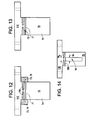
- FIGS. 12-14 illustrate machining steps for removal of the ears 73, 78 of the spacer shims 70 and T-shims 75, respectively.
- the ears 73, 78 are removed over the full length of the shim pack.
- FIG. 13 illustrates the welded top plate 110 and shim pack 115 with the ears 73, 78 removed from the shim pack.
- any current machining techniques can be implemented to remove the ears 73, 78, including but not limited to grinding, electrical discharge machining (EDM), and milling.
- FIG. 14 illustrates the welded top plate 110 and shim pack 115, now with the lower portions 74 of the spacer shims 70 removed, exposing the remaining T-shims 75. It is appreciated that the cutout 76 defines the slot 20 as described above.
- the cutout 76 and the slot 20 share the same width W 1 .
- the cutouts 76 of all the T-shims 75 are aligned along the shim pack 115.
- the depth of each of the welds 150 is such that a width W 4 of the remaining non-welded portions of the top plate 110 and the shim pack is less than the width W 1 of the cut out 76.
- the welds 150 do not extend past the cutout region but to a sufficient depth in order to secure the T-shims 75 and spacer shims 70 to the top plate, W4> W1.
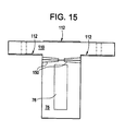
- FIG. 15 illustrates a front view of the top plate 110 and shim pack 115 combination.
- the top plate 110 defmes bend regions 112 such that the top plate 110 and shim pack 115 combination can be bent to a target diameter for the seal assembly as discussed above.
- the end regions 112 can be engaged by any current bending devices such as computer numerical control (CNC) rollers and custom dies or a press break and custom dies. It is appreciated that any current bending technique and apparatus can be implemented to create the target diameter and that the bend regions 112 provide a large enough surface area to accommodate the bending techniques and apparatuses.
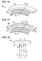
- FIG. 16 illustrates a perspective side view of a top plate 110 and shim pack 115 combination bent in accordance with exemplary embodiments.
- the top plate 110 and shim pack 115 combination is now referred to as an arcuate segment 160.
- FIG. 17 illustrates a perspective side view of the arcuate segment 160 with a central portion 161 of the top plate 110 machined out. Segment end ligaments 162, 163 of the arcuate segment 160 remain intact after the machining process to maintain proper registration and alignment of left and right portions of shims so that they are in the right location for subsequent operations.
- FIG. 18 illustrates a front view of the arcuate segment 160 of FIG. 17. FIG. 18 shows that the cut out section 76 and the central portion 161 are continuous forming the slot 76 of width W 1 .
- the weld 150 covers the entire length L of the top plate 110 and the T-shim 75 therefore providing a complete weld between the top plate 110 and each T-shim 75.
- FIG. 19 illustrates an arcuate segment 160 having an arcuate radial flow plate housing 170.
- the arcuate radial flow plate housing 170 is affixed to the arcuate segment via mechanical fasteners or welding as described above.
- the arcuate radial flow plate housing 170 is then machined to remove ends (including the ligaments 162, 163), generally shown as chord cuts 171, which are coplanar with the T-shim 70 at the chord cut 171.
- FIGS. 3-5 illustrate the implementation of welds 41 to affix the arcuate radial flow plate housing 170 to the arcuate segment.
- FIG. 2 illustrates a mechanically affixed arcuate radial flow plate housing 170.
- FIG. 20 illustrates an exemplary mechanically affixed arcuate radial flow plate housing 170.
- the arcuate segment 160 is machined as described above. The end cuts are made co-planar to the T-shims 70 as described.
- the arcuate radial flow plate housing 170 is then mechanically assembled to the arcuate segment 160.
- the exemplary manufacturing methods described herein provide a method suitable for automation in which machine-stacked alternating spacer and T-shim stampings are loaded into cartridges and the cartridges are slid into the electron beam weld fixture. This automated process minimizes manual assembly over the alternative, which is hand assembly to arcuate housings. Since all seals diameters are assembled and welded on the straight, no complex diameter dependant fixturing is required, which provides significant cost savings over one-off diameter dependant weld or braze fixtures.
- the manufacturing methods described herein further provide a cycle advantage, which facilitates manufacturing straight shim stock and bending it to the required diameter once an order is placed. With CNC roll bending die cost for different diameters if minimal.
- T-shims Full depth welds along the entire edges of T-shims can be made to fully join them to the top.
- Alternating spacer and T-shims are packed tightly in the straight weld body fixture at the required angle prescribed by the end fixture angle blocks. They are pressed tightly together utilizing the load screws on the end plates. This tight packing minimizes or eliminates gaps between welded shims. Therefore, when welded, the impact of weld shrinkage causing T-plate distortion is minimized. T-plate spacing is held very accurately, which minimizes T-shim stress and seal leakage on the finished product. Joining the shims in a straight configuration minimizes costs associated with custom fixturing for each seal diameter. Seals of any diameter can be bent from the straight stock.
Landscapes
- Engineering & Computer Science (AREA)
- General Engineering & Computer Science (AREA)
- Mechanical Engineering (AREA)
- Gasket Seals (AREA)
- Sealing Using Fluids, Sealing Without Contact, And Removal Of Oil (AREA)
- Sealing Devices (AREA)
- Turbine Rotor Nozzle Sealing (AREA)
- Sealing Battery Cases Or Jackets (AREA)
Description
- The subject matter disclosed herein relates to a sealing structure between a rotating component and a static component and, more particularly, to a compliant plate seal arrangement manufacturing method.
- Dynamic sealing between a rotor (e.g., rotating shaft) and a stator (e.g., static shell or casing) is an important concern in turbomachinery. Several methods of sealing have been used. In particular, sealing based on flexible members has been used that include seal members such as compliant plate seals.
- Known brush seals include tightly-packed, generally cylindrical bristles that are arranged in a staggered arrangement to reduce leakage. The bristles have a low radial stiffness that allows them to move in the event of a rotor excursion while maintaining a tight clearance during steady state operations. Brush seals, however, are generally effective only below a limited pressure differential across the seal. Because of the generally cylindrical geometry of the bristles, the brush seals tend to have a low stiffness in the axial direction, which limits the maximum operable pressure differential in known brush seals to generally less than 400 psi.
- Compliant plate seals have plate-like elements that have a significantly higher axial stiffness for a comparable radial stiffness and therefore such seals have the capability of being used with larger pressure differentials than known brush seals.
- Compliant plate seals, often including thin plate like elements assembled together as a pack, are welded to a housing that supports the plates relative to a rotor (e.g., a rotating shaft). One method of joining is by welding. During the welding process, the joined region of the compliant members can shrink which causes distortion and wrinkling of the compliant plate elements, which can affect the radial stiffness of and the force distribution on the compliant plates, which can lead to several problems including increased axial leakage and rotor heating.
-
US 2008/169614 describes a shaft seal assembly between a rotating shaft and a static shell, the shaft seal assembly including a seal housing in mechanical contact with the static shell, at least two rigid members of the seal housing, and a plurality of compliant plate members defining a sealing ring between the static shell and the rotating shaft. The plurality of compliant plate members is disposed between the at least two rigid members and retained within the seal housing by a compressive force between the at least two rigid members. -
US 2008/169614 discloses a compliant plate seal manufacturing method, comprising: assembling a plurality of t-shims and a plurality of spacer shims packed into a weld fixture at a prescribed angle, thereby forming a shim pack having a front and rear end and sides; welding the sides of the shim pack; removing a portion of the weld fixture [implicit from welding method]; removing the plurality of spacer shims; and shaping the shim pack into a target diameter" the shim pack includes a radial cutout region.Moreover,US 2008/169614 discloses a seal assembly, comprising: a top plate; a shim pack welded to the top plate, wherein the shim pack includes alternately arranged t-shims and spacer shims at an angle to the top plate in which a lower portion of the spacer shims have been removed; and a radial flow plate coupled to the top plate; wherein the top plate and shim pack assembly is bent into an arcuate segment to a prescribed diameter wherein the top plate includes a central portion machined to join a cut out on each of the t-shims, wherein ends of the arcuate seal segments are finished to a specified chord length and a finish cut is parallel to the plane of the t-shims and wherein tips of the t-shims are machined to a finished diameter. - According to the invention, there is provided a compliant plate seal manufacturing method, a compliant plate seal assembly manufactured according to the method and a weld fixture assembly configured to accommodate the compliant plate seal assembly during manufacture according to the method.
- These and other advantages and features will become more apparent from the following description taken in conjunction with the drawings.
- There follows a detailed description of embodiments of the invention by way of example only with reference to the accompanying drawings, in which:
-
FIG. 1 is a perspective view of an exemplary compliantplate seal assembly 10 as manufactured in accordance with exemplary embodiments; -
FIG. 2 is a cross-sectional view ofseal assembly 10 inFIG. 1 ; -
FIG. 3 is another cross-sectional view ofseal assembly 10 inFIG. 1 ; -
FIG. 4 is another cross-sectional view ofseal assembly 10 inFIG. 1 ; -
FIG. 5 is another cross-sectional view ofseal assembly 10 inFIG. 1 ; -
FIG. 6 is a cross-sectional view ofseal assembly 10 shown inFIG. 2 ; -
FIG. 7 illustrates a spacer shim and a T-shim in accordance with exemplary embodiments; -
FIG. 8 further illustrates a side view and a front view of the weld body fixture; -
FIG. 9 illustrates a front view of a top plate mechanically affixed to the weld fixture body with an assembled spacer shim; -
FIG. 10 illustrates a side section view of an assembled weld fixture assembly; -
FIG. 11 illustrates a front section view of the welded compliant plate seal still within the weld fixture illustrating welds along a weld region defined between a top plate and a shim pack; -
FIG. 12 illustrates the region of removal of the ears of the spacer shims and T-shims, implemented to drop out the bottom portion of the spacer shims; -
FIG. 13 illustrates the compliant plate seal after removal of ears of spacer shims and T-shims; -
FIG. 14 illustrates the compliant plate seal after removal of the bottom of the spacer shims below the joined region. -
FIG. 15 illustrates a front view of a top plate and a shim pack combination showing regions, which are the reaction points for the radial bending operation; -
FIG. 16 illustrates a perspective side view of a top plate and a shim pack combination after radial bend in accordance with exemplary embodiments; -
FIG. 17 illustrates a perspective side view of an arcuate segment with a central portion of a top plate machined out; -
FIG. 18 illustrates a front section view of the arcuate segment ofFIG. 17 ; -
FIG. 19 illustrates an arcuate segment having an arcuate radial flow plate housing; and -
FIG. 20 illustrates an exemplary mechanically affixed arcuate radial flow plate housing. - Exemplary embodiments include a compliant seal manufacturing method that reduces distortion, deformity, differential shrinkage and other associated problems with welding across gaps between compliant plate seals as is typical in current manufacturing processes. In exemplary embodiments, compliant plate seals are joined in a straight form and then later bent to a diameter suitable for use in sealing opposite a rotor. In exemplary embodiments, alternating spacer shims and T-shims are stacked in a straight fixture against angle blocks and compressed to eliminate any gaps. The spacer shims include a pocket that permits a later machining operation that removes a lower portion of the spacer. A top edge of the compressed shim pack is aligned against a top plate. A top flat surface of the shim pack is welded to the bottom surface of the top plate implementing a deep narrow electron beam or laser weld. A weld is performed on each side of the top plate. The left and right sides of the upper welded shim pack are machined to allow the lower portion of the spacer shims to be removed. After removal of the lower portion of the spacer shims, the top surface and the bottom left and right faces of the top plate are used to bend the seal into an arcuate segment of some prescribed diameter suitable for the final application in a turbomachine. After the bend, a center portion of the top plate is removed to permit assembly of a machined arcuate housing with a radial flow restrictor plate. The top housing is mechanically assembled or welded to the T-plate pack. The tips of the T-shims are machined to a final rotor diameter. The left and right sides of the assembly are machined off at an angle coplanar to the T-shim pack and at the required sealing segment chord length. There can be several segments per 360-degree seal.
- The entire edge of T-shims can be fully joined to the top plate by welding with a metallurgical bond, using a method of fixturing, which packs the shims very tightly. Therefore, when welded, the impact of weld shrinkage causing T-plate distortion is minimized. T-plate spacing is held very accurate with this method. This method also minimizes T-shim stress and leakage. Joining the leaves in a straight configuration minimizes costs associated with custom weld fixturing for each seal diameter. Seals of any diameter can be bent from the straight stock. An appropriate size spacer shim is chosen for the range of diameters being bent. The straight fixture allows precise axial positioning of thousands of shims to within several tenths of a mil or less. Accurate and repeatable spacing between compliant members is important to achieving minimum compliant plate stress during operation as well as minimized seal leakage. A straight method of stacking with alternating spacer shim and T-shims lends itself to a machine-based automated shim stack process, further reducing hand or manual stacking operations for assembling shims. This is a cost and cycle advantage over arcuate housings, which are assembled more manually.
- The improved compliant plate seal manufacturing method described herein provides a structure that prevents distortion, deformity, differential shrinkage and other associated problems with welding across gaps between compliant plate seals.
-
FIG. 1 is a perspective view of an exemplary compliantplate seal assembly 10 as manufactured in accordance with exemplary embodiments described herein.FIG. 2 is a cross-sectional view ofseal assembly 10 taken along line 2-2. More specifically, inFIG. 2 ,seal assembly 10 is illustrated in a radially outward or retracted position, as described herein.FIG. 6 is a cross-sectional view ofseal assembly 10 shown inFIG. 2 , with the presence of arotor 12. - In exemplary embodiments, the compliant
plate seal assembly 10 facilitates reducing axial leakage betweenrotor 12, such as a rotating shaft, and thehousing 14. More specifically, thehousing 14 is coupled to a turbine static shell or stator such thatrotor 12 rotates relative tohousing 14. In exemplary embodiments, thehousing 14 may be coupled within the stator.FIG. 2 illustrates setscrews 40 as coupling thehousing 14 to the joinedcomplaints plate members 16.FIGS. 3-5 illustrate alternate housing configurations and welds 41 as coupling the housing configurations to the compliant plate members. It is appreciated that any suitable housing configuration, coupling technique, and fastening technique can be implemented, which enablesseal assembly 10 to function as described herein. - The
shaft seal assembly 10 is provided with a plurality ofcompliant plate elements 16 secured at theirroots 26, in a facing relation (i.e., face-to-face). As used herein, the term "facing relation" refers an orientation in which afirst side surface 28 of onecompliant plate element 16 is adjacent to asecond side surface 30 of an immediate adjacentcompliant plate element 16. Eachside surface surface 32 at ahigh pressure side 33 to a trailingsurface 34 at alow pressure side 35 of each compliant plate element, and from aroot 26 to atip 36 of eachcompliant plate element 16. It is appreciated that the leadingsurfaces 32 and/or trailingsurfaces 34 ofelements 16 may be exposed athigh pressure side 33 and/orlow pressure side 35, respectively. In exemplary embodiments, eachcompliant plate element 16 is substantially planar, or flat, along eachside surface - Referring to
FIG. 6 , in exemplary embodiments, when plate elements have substantially constant thickness T, agap 38 is defined between adjacentcompliant plate elements 16 such thatgap 38 is wider at an outer portion 42 than at an inner portion 44. As further described herein, the gap is pre-defined accordingly by the presence of spacer shims (not shown) alternately positioned between adjacentcompliant plate elements 16 and selectively removed. Accordingly,gap 38 tapers from outer portion 42 towards inner portion 44. As such,roots 26 ofplate members 16 may be considered to be "loosely packed," andtips 36 may be considered to be "tightly packed." The term "tightly packed," as used herein, refers to an orientation in whichadjacent plate tips 36 are not in contact with each other but are closely spaced. - In exemplary embodiments, the
compliant plate elements 16 are coupled tohousing 14 such that eachplate element 16 is oriented at an angle θ (also referred to herein as a "cant angle") relative to a respectivetangent plane 48 ofrotor 12. Thetangent plane 48 is defmed at aline 50 onrotor 12 that is proximate toplate tip 36. More specifically, at least one of the side surfaces 28 and/or 30 is oriented at angle θ relative totangent plane 48. In exemplary embodiments, the cant angle θ is less than 90°. In one embodiment, cant angle θ is selected to be some specific prescribed value between approximately 20° and approximately 70°. In the exemplary embodiment, the cant angle θ is selected to ensure thatplate elements 16 are angled away from a direction R of rotation ofrotor 12 such that the cant angle θ facilitates rotation ofrotor 12 withinseal assembly 10. - Referring to
FIG. 1 , an axialflow resistance member 17 extends at least partially throughcompliant plate elements 16 via aslot 20 and facilitates preventing axial leakage flow betweengaps 38. More specifically, in the exemplary embodiment,resistance member 17 extends circumferentially abouthousing 14, and extends radially inward fromhousing 14 towardsrotor 12. - Referring to
FIG. 2 , in exemplary embodiments, theslot 20 and the axialflow resistance member 17 has a substantially constant width W1, W2, respectively. Furthermore, the axialflow resistance member 17 can include anupper portion 18 having width W3, which can be substantially equal to the width W1 of theslot 20. Alternatively, widths W1, W2, W3, may be of any size that enablesseal assembly 10 to function as described herein. Moreover, agap 58 is defined between the axialflow resistance member 17 and theslot 20. In exemplary embodiments, thegap 58 includes afront section 62, abridge section 63, and aback section 64. InFIG. 2 , theslot 20 ofcompliant plate 16 and axialflow resistance member 17 ofhousing 14 are shown in the center ofcompliant plate member 16. In an alternative embodiment, the axialflow resistance member 17 and theslot 20 of the compliant plate may be offset in the axial direction from the center ofhousing 14. - In exemplary embodiments, dimensions of the
gap 58 are selected based on predetermined hydrostatic lift and/or hydrostatic blowdown conditions. For example, thefront section 62 may decrease whileback section 64 increases. Such a gap configuration may cause hydrostatic blowdown. As used herein, the term "blowdown" refers to a radially inward deflection ofcompliant plate elements 16 under a pressure loading. In an alternative embodiment, thefront section 62 may be larger than backsection 64. Such a gap configuration may cause lift onplate elements 16. In exemplary embodiments, thecompliant plate elements 16 experience an effective blowdown force nearfront section 62 and an effective lift force nearback section 64, wherein front andback sections gap sections compliant plate member 16 is facilitated to be reduced, as compared to known compliant plate seal assemblies. - Exemplary methods for manufacturing the
seal assembly 10 are now described.FIG. 7 illustrates aspacer shim 70 and T-shim 75 prior to manufacturing into theseal assembly 10 in accordance with exemplary embodiments. During manufacturing of theseal assembly 10 alternating rows of spacer shims 70 and T-shims 75 are tightly packed as a first step in forming thecompliant plate members 16. In exemplary embodiments, thespacer shim 70 is implemented to provide the required spacing between each of the T-shims 75 in the alternately packed arrangement. The spacer shims 70 include a cut outregion 71 within an upper T-region 72 of the spacer shim. As further described herein,ears 73 of the upper T-region 72 are later machined off on the left and right and then aportion 74 of thespacer shim 70 below the cut outregion 71 drops out of theseal assembly 10. Thickness of thespacer shim 70 can be selected as some thickness value generally within the range 0.0005" to 0.004" to define thegap 38. In exemplary embodiments, the T-shims 75 are the shims or plates that include the flexible part of the seal assembly and are a portion of thecomplaint plate member 16. Acenter cutout 76 later defines theslot 20 that includes the radially oriented axialflow resistance member 17. The T-shims 75 further includes an upper T-region 77 that includesears 78 that are machined off later along with theears 73 of the spacer shims 70. The thickness of the T-shim 75 is selected as some thickness value generally within the range .002" to .030" as labeled T inFIG. 6 . This manufacturing technique does not limit the spacer thickness and can work for any practical thickness larger or smaller than the specified range. -
FIGS. 8 & 9 illustrates a side and front view of aweld fixture body 100 into which the spacer shims 70 and the T-shims 75 are alternately packed along a straight line as described above. In exemplary embodiments, the spacer shims 70 and the T-shims 75 are alternately packed within achannel 105 defined within thefixture body 100. The weld fixture body further includes a cut-outregion 106, which defines a window for welding as further described herein.FIG. 9 illustrates a front view of theweld fixture body 100 assembled with the alternately spaced spacer shims 70 and T-shims 75. Aspacer shim 70 is shown.FIG. 9 further illustrates atop plate 110 mechanically affixed to the weld fixture body. In exemplary embodiments,bolts 111 mechanically affix thetop plate 110 to theweld fixture body 100. -
FIG. 10 illustrates a side section view of an assembledweld fixture assembly 180.FIG. 11 illustrates a front section view of the welded compliant plate seal still within theweld fixture assembly 180. Theweld fixture assembly 180 includes theweld fixture body 100 and thetop plate 110 as described above. Theweld fixture assembly 180 further includes the alternating spacer shims 70 and T-shims, now referred to as theshim pack 115. Left and right angle blocks 120, 125 are inserted into thechannel 105 of theweld fixture body 100 on opposite ends of theshim pack 115. The angle blocks 120, 125 establish a fixture block angle ϕ of theshim pack 115 with respect to thetop plate 110. The fixture block angle ϕ is selected to correspond with a desired angle of theshim pack 115 welded to thetop plate 110. In exemplary embodiments, the angle ϕ can be selected as 45 degrees. A left andright end plate weld fixture body 100. Theend plates weld fixture body 100 viabolts 136. Theend plates shim pack 115. Loading screws 140 can be adjusted to push the end block and sliding it to compress theshim pack 115 to minimize any spaces in aweld region 145 of theshim pack 115. Theweld region 145 of theshim pack 115 is exposed through theweld fixture body 100 through awindow 150 defined between thetop plate 110 and the cut outregion 106 as described above. - In exemplary embodiments, a weld beam is focused into the
window 150 along theweld region 145 in order to weld theshim pack 115 to thetop plate 110. The weld beam can be an electron beam, which provides a thin and narrow beam to minimize heating of thetop plate 110 as well as a deep weld along thetop plate 110 andshim pack 115.FIG. 11 illustrateswelds 155 along theweld region 145 defined between thetop plate 110 and theshim pack 115. As further described herein, thewelds 155 runs to a depth that is past the cut out regions of both the spacer shims 70 and T-shims 75. In an alternate exemplary embodiment, thewelds 155 do not extend past the cut out regions of the both the spacer shims 70 and T-shims 75. - In exemplary embodiments, after welding, the
end plates weld fixture body 100. The angle blocks 120, 125 are also removed from theweld fixture body 100. As a result of the weld process described above, thetop plate 110 and theshim pack 115 are now welded together and are also removed as a joined assembly from theweld fixture body 100. -
FIGS. 12-14 illustrate machining steps for removal of theears shims 75, respectively. InFIG. 12 theears FIG. 13 illustrates the weldedtop plate 110 andshim pack 115 with theears ears ears 73 of the spacer shims 70 removed, it is appreciated that thelower portion 74 of thespacer shim 70 is no longer supported to or attached to the upper T portion (withears 73 removed), which is welded to thetop plate 110. As such, thelower portions 74 of the spacer shims 70 fall away from thetop plate 110 andshim pack 115 assembly. The remainingupper portions 72 define the spacing (and thus the gap 38) between the remaining T-shims 75.FIG. 14 illustrates the weldedtop plate 110 andshim pack 115, now with thelower portions 74 of the spacer shims 70 removed, exposing the remaining T-shims 75. It is appreciated that thecutout 76 defines theslot 20 as described above. It is further appreciated that thecutout 76 and theslot 20 share the same width W1. In addition, thecutouts 76 of all the T-shims 75 are aligned along theshim pack 115. It is further appreciated that the depth of each of thewelds 150 is such that a width W4 of the remaining non-welded portions of thetop plate 110 and the shim pack is less than the width W1 of the cut out 76. In an alternate exemplary embodiment, thewelds 150 do not extend past the cutout region but to a sufficient depth in order to secure the T-shims 75 andspacer shims 70 to the top plate, W4> W1. -
FIG. 15 illustrates a front view of thetop plate 110 andshim pack 115 combination. Thetop plate 110 defmes bendregions 112 such that thetop plate 110 andshim pack 115 combination can be bent to a target diameter for the seal assembly as discussed above. Theend regions 112 can be engaged by any current bending devices such as computer numerical control (CNC) rollers and custom dies or a press break and custom dies. It is appreciated that any current bending technique and apparatus can be implemented to create the target diameter and that thebend regions 112 provide a large enough surface area to accommodate the bending techniques and apparatuses.FIG. 16 illustrates a perspective side view of atop plate 110 andshim pack 115 combination bent in accordance with exemplary embodiments. Thetop plate 110 andshim pack 115 combination is now referred to as anarcuate segment 160. -
FIG. 17 illustrates a perspective side view of thearcuate segment 160 with acentral portion 161 of thetop plate 110 machined out.Segment end ligaments arcuate segment 160 remain intact after the machining process to maintain proper registration and alignment of left and right portions of shims so that they are in the right location for subsequent operations.FIG. 18 illustrates a front view of thearcuate segment 160 ofFIG. 17. FIG. 18 shows that the cut outsection 76 and thecentral portion 161 are continuous forming theslot 76 of width W1. In addition, it is appreciated that theweld 150 covers the entire length L of thetop plate 110 and the T-shim 75 therefore providing a complete weld between thetop plate 110 and each T-shim 75. - Referring again to
FIGS. 2-5 , embodiments of ahousing 14 including an integral axialflow resistance member 17 are illustrated. The housing and the axialflow resistance member 17 are now referred to as an arcuate radialflow plate housing 170 as shown inFIG. 20. FIG. 19 illustrates anarcuate segment 160 having an arcuate radialflow plate housing 170. In exemplary embodiments, the arcuate radialflow plate housing 170 is affixed to the arcuate segment via mechanical fasteners or welding as described above. The arcuate radialflow plate housing 170 is then machined to remove ends (including theligaments 162, 163), generally shown as chord cuts 171, which are coplanar with the T-shim 70 at the chord cut 171. The cross sectional view forFIGS. 3-5 is shown inFIG. 19 .FIGS. 3-5 illustrate the implementation ofwelds 41 to affix the arcuate radialflow plate housing 170 to the arcuate segment.FIG. 2 illustrates a mechanically affixed arcuate radialflow plate housing 170.FIG. 20 illustrates an exemplary mechanically affixed arcuate radialflow plate housing 170. For the mechanically affixed arcuate radialflow plate housing 170, thearcuate segment 160 is machined as described above. The end cuts are made co-planar to the T-shims 70 as described. The arcuate radialflow plate housing 170 is then mechanically assembled to thearcuate segment 160. - The exemplary manufacturing methods described herein provide a method suitable for automation in which machine-stacked alternating spacer and T-shim stampings are loaded into cartridges and the cartridges are slid into the electron beam weld fixture. This automated process minimizes manual assembly over the alternative, which is hand assembly to arcuate housings. Since all seals diameters are assembled and welded on the straight, no complex diameter dependant fixturing is required, which provides significant cost savings over one-off diameter dependant weld or braze fixtures. The manufacturing methods described herein further provide a cycle advantage, which facilitates manufacturing straight shim stock and bending it to the required diameter once an order is placed. With CNC roll bending die cost for different diameters if minimal. Full depth welds along the entire edges of T-shims can be made to fully join them to the top. Alternating spacer and T-shims are packed tightly in the straight weld body fixture at the required angle prescribed by the end fixture angle blocks. They are pressed tightly together utilizing the load screws on the end plates. This tight packing minimizes or eliminates gaps between welded shims. Therefore, when welded, the impact of weld shrinkage causing T-plate distortion is minimized. T-plate spacing is held very accurately, which minimizes T-shim stress and seal leakage on the finished product. Joining the shims in a straight configuration minimizes costs associated with custom fixturing for each seal diameter. Seals of any diameter can be bent from the straight stock. An appropriately sized spacer shim is chosen for the range of diameters being bent. The straight weld fixture allows precise axial positioning of thousands of shims to within a few mils. Stacking with alternating spacer shims and T-shims lends itself to a machine-based automated shim stack process, which further reduces hand or manual stacking operations for assembling shims. This is a cost and cycle advantage over processes that must be done manually.
- While the invention has been described in detail in connection with only a limited number of embodiments, it should be readily understood that the invention is not limited to such disclosed embodiments. Rather, the invention can be modified to incorporate any number of variations, alterations, substitutions or equivalent arrangements not heretofore described, but which are commensurate with the spirit and scope of the invention. Additionally, while various embodiments of the invention have been described, it is to be understood that aspects of the invention may include only some of the described embodiments. Accordingly, the invention is not to be seen as limited by the foregoing description, but is only limited by the scope of the appended claims.
Claims (15)
- A compliant plate seal manufacturing method, comprising:assembling a plurality of t-shims (75) and a plurality of spacer shims (70) packed into a weld fixture (100) at a prescribed angle, thereby forming a shim pack (115) having a front and rear end and sides, each of the plurality of t-shims (75) and spacer shims (70) including a cut-out region (71, 76);welding the sides of the shim pack (115);removing a portion of the weld fixture (100);removing a lower portion of each of the plurality of spacer shims (70); andshaping the shim pack (115) into a target diameter.
- The method as claimed in claim 1, further comprising applying a radial flow plate (170) to the shim pack (115).
- The method as claimed in claim 1 or 2, wherein the sides of the shim pack (115) are welded to a top plate (110) also secured within the weld fixture (100), wherein the top plate (110) includes a central portion (161) removed after shaping and machined to join the cut-out region (76) on each of the t-shims (75) and wherein the top plate (110) and the shim pack (115) are removed from the weld fixture (100).
- The method as claimed in any of the preceding claims, wherein an upper portion of the spacer shims (70) and the T-shims (75) are welded to the top plate (110) during welding the sides of the shim pack (115).
- The method as claimed in any of the preceding claims, wherein the plurality of t-shims (75) and the plurality of spacer shims (70) are alternately packed into the weld fixture (100).
- The method as claimed in any preceding claim, further comprising removing a portion of the sides of the spacer shims (70) and T-shims (75) to remove the bottom portion of the spacer shims (70) below the spacer shim (70) cut-out.
- The method as claimed in any of claims 3 to 6, further comprising performing a radial bend of the joined top plate (110) and shim pack (115) assembly forming a shape of at least one of a shaft seal or an arcuate segment (160) of a shaft seal.
- The method as claimed in claim 7, wherein the top plate (110) is machined after welding to make it thinner, prior to radial bend.
- The method as claimed in any of claims 3 to 8, wherein the radial flow plate (170) is affixed adjacent to or within the removed central portion (161) of the top plate (110).
- The method as claimed in claim 9, wherein the cut-out region (76) of each of the t-shims (75) is aligned with the removed central portion of the top plate (110).
- A compliant plate seal assembly manufactured according to the method of any of claims 1 to 10, the seal assembly comprising:a top plate (110);a shim pack (115) welded to the top plate (110), wherein the shim pack (115) includes alternately arranged t-shims (75) and spacer shims (70) at an angle to the top plate (110), each of the t-shims (75) and spacer shims (70) including a cut-out region (71,76) and wherein a lower portion of the spacer shims (70) have been removed; anda radial flow plate (170) coupled to the top plate (110);wherein the top plate (110) and shim pack (115) is bent into an arcuate segment (160) to a prescribed diameter;wherein the top plate (110) includes a removed central portion (161) that is machined to join the cut-out region (76) on each of the t-shims (75);wherein ends of the arcuate seal segments (160) are finished to a specified chord length and a finish cut is parallel to the plane of the t-shims (75); andwherein tips of the t-shims (75) are machined to a finished diameter.
- The assembly as claimed in claim 11, wherein a weld between the top plate (110) and each of the t-shims (75) extends from an outer portion of the shim pack (115) to the cutout (76) of each of the t-shims (75).
- A weld fixture assembly (180), configured to accommodate the compliant plate seal assembly during manufacture according to the method of any of claims 1 to 10, and further comprising
a weld fixture body (100) having an elongate channel (105) including flat surfaces to position the shim pack (115) of the compliant plate seal;
an angle block (120, 125) disposed on either end of the shim pack (115) establishing an angle of the shim pack (115) with respect to the top plate (110) of the seal assembly;
end plates (130, 135) coupled to either end of the weld fixture body (100) including jack screws (140) configured to compress the shim pack (115) to reduce gaps; and
a window (150) formed between the top plate (110) and the weld fixture body (100). - The assembly as claimed in claim 13, further comprising a weld region exposed via the window (150), the weld region (145) being defined between the top plate (110) and the shim pack (115).
- The assembly as claimed in claims 13 or 14, wherein the window (150) is configured to receive at least one of an electron beam and a laser beam for welding the weld region (145).
Applications Claiming Priority (1)
| Application Number | Priority Date | Filing Date | Title |
|---|---|---|---|
| US12/389,757 US8250756B2 (en) | 2009-02-20 | 2009-02-20 | Method of manufacture of compliant plate seals |
Publications (3)
| Publication Number | Publication Date |
|---|---|
| EP2221514A2 EP2221514A2 (en) | 2010-08-25 |
| EP2221514A3 EP2221514A3 (en) | 2013-03-13 |
| EP2221514B1 true EP2221514B1 (en) | 2015-04-08 |
Family
ID=42167587
Family Applications (1)
| Application Number | Title | Priority Date | Filing Date |
|---|---|---|---|
| EP10153023.6A Not-in-force EP2221514B1 (en) | 2009-02-20 | 2010-02-09 | Method of manufacture of compliant plate seals |
Country Status (4)
| Country | Link |
|---|---|
| US (1) | US8250756B2 (en) |
| EP (1) | EP2221514B1 (en) |
| JP (1) | JP5491229B2 (en) |
| RU (1) | RU2010105922A (en) |
Families Citing this family (17)
| Publication number | Priority date | Publication date | Assignee | Title |
|---|---|---|---|---|
| US20100143102A1 (en) * | 2008-02-18 | 2010-06-10 | General Electric Company | Compliant plate seal with self-correcting behavior |
| JP5473685B2 (en) * | 2010-03-10 | 2014-04-16 | 三菱重工業株式会社 | Shaft sealing device and rotary machine equipped with shaft sealing device |
| GB201113590D0 (en) | 2011-08-08 | 2011-09-21 | Rolls Royce Plc | Leaf seal |
| GB201117729D0 (en) * | 2011-10-14 | 2011-11-23 | Rolls Royce Plc | Leaf seal manufacturing method |
| US9103224B2 (en) | 2011-12-29 | 2015-08-11 | General Electric Company | Compliant plate seal for use with rotating machines and methods of assembling a rotating machine |
| GB201209389D0 (en) * | 2012-05-28 | 2012-07-11 | Rolls Royce Plc | Seal and method of forming a seal |
| GB201209705D0 (en) * | 2012-05-31 | 2012-07-18 | Rolls Royce Plc | Leaf seal |
| US20140205440A1 (en) * | 2013-01-18 | 2014-07-24 | General Electric Company | Compliant plate seals for rotary machines |
| JP6125412B2 (en) * | 2013-11-22 | 2017-05-10 | 三菱重工業株式会社 | Shaft sealing device, rotating machine, and manufacturing method of shaft sealing device |
| US9377108B2 (en) | 2013-11-22 | 2016-06-28 | General Electric Company | Variable stiffness compliant plate seal |
| CN105134305B (en) * | 2014-06-09 | 2017-04-12 | 斗山重工业株式会社 | Brush seal assembly |
| US9784116B2 (en) | 2015-01-15 | 2017-10-10 | General Electric Company | Turbine shroud assembly |
| JP6358976B2 (en) * | 2015-02-20 | 2018-07-18 | 三菱日立パワーシステムズ株式会社 | Turbine sealing device and turbine, and thin plate for sealing device |
| JP6675262B2 (en) * | 2016-05-09 | 2020-04-01 | 三菱日立パワーシステムズ株式会社 | Seal segment and rotating machine |
| JP6631837B2 (en) * | 2016-05-09 | 2020-01-15 | 三菱日立パワーシステムズ株式会社 | Seal segment and rotating machine |
| US10655489B2 (en) | 2018-01-04 | 2020-05-19 | General Electric Company | Systems and methods for assembling flow path components |
| CN108838629B (en) * | 2018-08-07 | 2021-01-22 | 南通中能机械制造有限公司 | Novel method for processing rhombic two-side-face tooth-shaped movable partition leaf piece |
Family Cites Families (15)
| Publication number | Priority date | Publication date | Assignee | Title |
|---|---|---|---|---|
| US4989919A (en) * | 1988-08-30 | 1991-02-05 | Pratt & Whitney Canada | Method and apparatus for manufacturing compliant brush seals |
| US6840519B2 (en) * | 2001-10-30 | 2005-01-11 | General Electric Company | Actuating mechanism for a turbine and method of retrofitting |
| US6786487B2 (en) * | 2001-12-05 | 2004-09-07 | General Electric Company | Actuated brush seal |
| JP4081719B2 (en) | 2003-05-30 | 2008-04-30 | イーグル・エンジニアリング・エアロスペース株式会社 | Plate brush seal device |
| JP3993536B2 (en) | 2003-06-20 | 2007-10-17 | 三菱重工業株式会社 | Manufacturing method of shaft seal, shaft seal, shaft seal member, and rotary machine using shaft seal |
| DE102004016173A1 (en) | 2004-03-30 | 2005-10-20 | Alstom Technology Ltd Baden | Lamella seal, in particular for a gas turbine, and method for its production |
| DE102004020378A1 (en) * | 2004-04-23 | 2005-11-10 | Alstom Technology Ltd | Lamella seal, in particular for a gas turbine, and method for its production |
| JP3970298B2 (en) * | 2005-11-10 | 2007-09-05 | 三菱重工業株式会社 | Shaft seal mechanism |
| GB0613989D0 (en) | 2006-07-14 | 2006-08-23 | Rolls Royce Plc | leaf Seals |
| US8382119B2 (en) | 2006-08-15 | 2013-02-26 | General Electric Company | Compliant plate seals for turbomachinery |
| US7419164B2 (en) * | 2006-08-15 | 2008-09-02 | General Electric Company | Compliant plate seals for turbomachinery |
| US7703774B2 (en) | 2006-09-12 | 2010-04-27 | General Electric Company | Shaft seal using shingle members |
| US20080107525A1 (en) * | 2006-11-02 | 2008-05-08 | General Electric Company | Shaft seal formed of tapered compliant plate members |
| US20080169614A1 (en) | 2007-01-12 | 2008-07-17 | Shorya Awtar | Compliant plate seal assembly apparatus and assembly method thereof |
| US8794631B2 (en) * | 2009-01-12 | 2014-08-05 | General Electric Company | Method of manufacturing of a compliant plate seal assembly |
-
2009
- 2009-02-20 US US12/389,757 patent/US8250756B2/en active Active
-
2010
- 2010-02-09 EP EP10153023.6A patent/EP2221514B1/en not_active Not-in-force
- 2010-02-17 JP JP2010031905A patent/JP5491229B2/en not_active Expired - Fee Related
- 2010-02-19 RU RU2010105922/06A patent/RU2010105922A/en not_active Application Discontinuation
Also Published As
| Publication number | Publication date |
|---|---|
| RU2010105922A (en) | 2011-08-27 |
| US8250756B2 (en) | 2012-08-28 |
| EP2221514A3 (en) | 2013-03-13 |
| JP5491229B2 (en) | 2014-05-14 |
| EP2221514A2 (en) | 2010-08-25 |
| US20100213675A1 (en) | 2010-08-26 |
| JP2010196893A (en) | 2010-09-09 |
Similar Documents
| Publication | Publication Date | Title |
|---|---|---|
| EP2221514B1 (en) | Method of manufacture of compliant plate seals | |
| US8794631B2 (en) | Method of manufacturing of a compliant plate seal assembly | |
| US8585058B2 (en) | Leaf seal and method of producing a leaf seal | |
| EP1808577B1 (en) | A welded nozzle assembly for a steam turbine | |
| JP4675530B2 (en) | Plate brush seal | |
| US10030529B2 (en) | Combined featherseal slot and lightening pocket | |
| US7997860B2 (en) | Welded nozzle assembly for a steam turbine and related assembly fixtures | |
| US8702385B2 (en) | Welded nozzle assembly for a steam turbine and assembly fixtures | |
| US20080099999A1 (en) | Leaf seals | |
| JP5342579B2 (en) | Stator blade unit of rotating machine, method of manufacturing stator blade unit of rotating machine, and method of coupling stator blade unit of rotating machine | |
| GB2413977A (en) | Method of manufacturing thin wall isogrid casings | |
| US7270333B2 (en) | Brush seal with adjustable clearance | |
| JP2013155784A (en) | Shaft seal device | |
| EP3800004B1 (en) | Method of repair to compressor housing and repaired housing | |
| US4743126A (en) | Hydrodynamic bearings, and secondary assemblies for producing said bearings | |
| CN111541314A (en) | Stator core of motor and motor | |
| US20170101989A1 (en) | Methods for making a low inertia laminated rotor | |
| Adis et al. | Side Weld and Bend Method of Manufacturing Compliant Plate Seals | |
| JP4091806B2 (en) | Manufacturing method of plate brush seal split veneer | |
| JP4091807B2 (en) | Manufacturing method of plate brush seal split veneer | |
| JP4242615B2 (en) | Manufacturing method of plate brush seal veneer | |
| US20110314660A1 (en) | Spin weld method of manufacturing induction rotors | |
| CN114536245A (en) | Center for cooling in laser cladding tube and assembling method thereof |
Legal Events
| Date | Code | Title | Description |
|---|---|---|---|
| PUAI | Public reference made under article 153(3) epc to a published international application that has entered the european phase |
Free format text: ORIGINAL CODE: 0009012 |
|
| AK | Designated contracting states |
Kind code of ref document: A2 Designated state(s): AT BE BG CH CY CZ DE DK EE ES FI FR GB GR HR HU IE IS IT LI LT LU LV MC MK MT NL NO PL PT RO SE SI SK SM TR |
|
| AX | Request for extension of the european patent |
Extension state: AL BA RS |
|
| PUAL | Search report despatched |
Free format text: ORIGINAL CODE: 0009013 |
|
| AK | Designated contracting states |
Kind code of ref document: A3 Designated state(s): AT BE BG CH CY CZ DE DK EE ES FI FR GB GR HR HU IE IS IT LI LT LU LV MC MK MT NL NO PL PT RO SE SI SK SM TR |
|
| AX | Request for extension of the european patent |
Extension state: AL BA RS |
|
| RIC1 | Information provided on ipc code assigned before grant |
Ipc: F16J 15/32 20060101AFI20130205BHEP |
|
| 17P | Request for examination filed |
Effective date: 20130913 |
|
| RBV | Designated contracting states (corrected) |
Designated state(s): AT BE BG CH CY CZ DE DK EE ES FI FR GB GR HR HU IE IS IT LI LT LU LV MC MK MT NL NO PL PT RO SE SI SK SM TR |
|
| GRAP | Despatch of communication of intention to grant a patent |
Free format text: ORIGINAL CODE: EPIDOSNIGR1 |
|
| INTG | Intention to grant announced |
Effective date: 20140903 |
|
| GRAP | Despatch of communication of intention to grant a patent |
Free format text: ORIGINAL CODE: EPIDOSNIGR1 |
|
| GRAS | Grant fee paid |
Free format text: ORIGINAL CODE: EPIDOSNIGR3 |
|
| INTG | Intention to grant announced |
Effective date: 20150121 |
|
| GRAA | (expected) grant |
Free format text: ORIGINAL CODE: 0009210 |
|
| AK | Designated contracting states |
Kind code of ref document: B1 Designated state(s): AT BE BG CH CY CZ DE DK EE ES FI FR GB GR HR HU IE IS IT LI LT LU LV MC MK MT NL NO PL PT RO SE SI SK SM TR |
|
| REG | Reference to a national code |
Ref country code: GB Ref legal event code: FG4D |
|
| REG | Reference to a national code |
Ref country code: CH Ref legal event code: EP |
|
| REG | Reference to a national code |
Ref country code: IE Ref legal event code: FG4D |
|
| REG | Reference to a national code |
Ref country code: AT Ref legal event code: REF Ref document number: 720849 Country of ref document: AT Kind code of ref document: T Effective date: 20150515 |
|
| REG | Reference to a national code |
Ref country code: DE Ref legal event code: R096 Ref document number: 602010023707 Country of ref document: DE Effective date: 20150521 |
|
| REG | Reference to a national code |
Ref country code: AT Ref legal event code: MK05 Ref document number: 720849 Country of ref document: AT Kind code of ref document: T Effective date: 20150408 |
|
| REG | Reference to a national code |
Ref country code: NL Ref legal event code: VDEP Effective date: 20150408 |
|
| REG | Reference to a national code |
Ref country code: LT Ref legal event code: MG4D |
|
| PG25 | Lapsed in a contracting state [announced via postgrant information from national office to epo] |
Ref country code: NL Free format text: LAPSE BECAUSE OF FAILURE TO SUBMIT A TRANSLATION OF THE DESCRIPTION OR TO PAY THE FEE WITHIN THE PRESCRIBED TIME-LIMIT Effective date: 20150408 |
|
| PG25 | Lapsed in a contracting state [announced via postgrant information from national office to epo] |
Ref country code: ES Free format text: LAPSE BECAUSE OF FAILURE TO SUBMIT A TRANSLATION OF THE DESCRIPTION OR TO PAY THE FEE WITHIN THE PRESCRIBED TIME-LIMIT Effective date: 20150408 Ref country code: FI Free format text: LAPSE BECAUSE OF FAILURE TO SUBMIT A TRANSLATION OF THE DESCRIPTION OR TO PAY THE FEE WITHIN THE PRESCRIBED TIME-LIMIT Effective date: 20150408 Ref country code: NO Free format text: LAPSE BECAUSE OF FAILURE TO SUBMIT A TRANSLATION OF THE DESCRIPTION OR TO PAY THE FEE WITHIN THE PRESCRIBED TIME-LIMIT Effective date: 20150708 Ref country code: PT Free format text: LAPSE BECAUSE OF FAILURE TO SUBMIT A TRANSLATION OF THE DESCRIPTION OR TO PAY THE FEE WITHIN THE PRESCRIBED TIME-LIMIT Effective date: 20150810 Ref country code: LT Free format text: LAPSE BECAUSE OF FAILURE TO SUBMIT A TRANSLATION OF THE DESCRIPTION OR TO PAY THE FEE WITHIN THE PRESCRIBED TIME-LIMIT Effective date: 20150408 Ref country code: HR Free format text: LAPSE BECAUSE OF FAILURE TO SUBMIT A TRANSLATION OF THE DESCRIPTION OR TO PAY THE FEE WITHIN THE PRESCRIBED TIME-LIMIT Effective date: 20150408 |
|
| PG25 | Lapsed in a contracting state [announced via postgrant information from national office to epo] |
Ref country code: IS Free format text: LAPSE BECAUSE OF FAILURE TO SUBMIT A TRANSLATION OF THE DESCRIPTION OR TO PAY THE FEE WITHIN THE PRESCRIBED TIME-LIMIT Effective date: 20150808 Ref country code: GR Free format text: LAPSE BECAUSE OF FAILURE TO SUBMIT A TRANSLATION OF THE DESCRIPTION OR TO PAY THE FEE WITHIN THE PRESCRIBED TIME-LIMIT Effective date: 20150709 Ref country code: LV Free format text: LAPSE BECAUSE OF FAILURE TO SUBMIT A TRANSLATION OF THE DESCRIPTION OR TO PAY THE FEE WITHIN THE PRESCRIBED TIME-LIMIT Effective date: 20150408 Ref country code: AT Free format text: LAPSE BECAUSE OF FAILURE TO SUBMIT A TRANSLATION OF THE DESCRIPTION OR TO PAY THE FEE WITHIN THE PRESCRIBED TIME-LIMIT Effective date: 20150408 |
|
| REG | Reference to a national code |
Ref country code: DE Ref legal event code: R097 Ref document number: 602010023707 Country of ref document: DE |
|
| PG25 | Lapsed in a contracting state [announced via postgrant information from national office to epo] |
Ref country code: DK Free format text: LAPSE BECAUSE OF FAILURE TO SUBMIT A TRANSLATION OF THE DESCRIPTION OR TO PAY THE FEE WITHIN THE PRESCRIBED TIME-LIMIT Effective date: 20150408 Ref country code: EE Free format text: LAPSE BECAUSE OF FAILURE TO SUBMIT A TRANSLATION OF THE DESCRIPTION OR TO PAY THE FEE WITHIN THE PRESCRIBED TIME-LIMIT Effective date: 20150408 |
|
| PLBE | No opposition filed within time limit |
Free format text: ORIGINAL CODE: 0009261 |
|
| STAA | Information on the status of an ep patent application or granted ep patent |
Free format text: STATUS: NO OPPOSITION FILED WITHIN TIME LIMIT |
|
| PG25 | Lapsed in a contracting state [announced via postgrant information from national office to epo] |
Ref country code: CZ Free format text: LAPSE BECAUSE OF FAILURE TO SUBMIT A TRANSLATION OF THE DESCRIPTION OR TO PAY THE FEE WITHIN THE PRESCRIBED TIME-LIMIT Effective date: 20150408 Ref country code: RO Free format text: LAPSE BECAUSE OF NON-PAYMENT OF DUE FEES Effective date: 20150408 Ref country code: PL Free format text: LAPSE BECAUSE OF FAILURE TO SUBMIT A TRANSLATION OF THE DESCRIPTION OR TO PAY THE FEE WITHIN THE PRESCRIBED TIME-LIMIT Effective date: 20150408 Ref country code: SK Free format text: LAPSE BECAUSE OF FAILURE TO SUBMIT A TRANSLATION OF THE DESCRIPTION OR TO PAY THE FEE WITHIN THE PRESCRIBED TIME-LIMIT Effective date: 20150408 |
|
| 26N | No opposition filed |
Effective date: 20160111 |
|
| PG25 | Lapsed in a contracting state [announced via postgrant information from national office to epo] |
Ref country code: IT Free format text: LAPSE BECAUSE OF FAILURE TO SUBMIT A TRANSLATION OF THE DESCRIPTION OR TO PAY THE FEE WITHIN THE PRESCRIBED TIME-LIMIT Effective date: 20150408 |
|
| PG25 | Lapsed in a contracting state [announced via postgrant information from national office to epo] |
Ref country code: SI Free format text: LAPSE BECAUSE OF FAILURE TO SUBMIT A TRANSLATION OF THE DESCRIPTION OR TO PAY THE FEE WITHIN THE PRESCRIBED TIME-LIMIT Effective date: 20150408 Ref country code: BE Free format text: LAPSE BECAUSE OF NON-PAYMENT OF DUE FEES Effective date: 20160229 |
|
| PG25 | Lapsed in a contracting state [announced via postgrant information from national office to epo] |
Ref country code: BE Free format text: LAPSE BECAUSE OF FAILURE TO SUBMIT A TRANSLATION OF THE DESCRIPTION OR TO PAY THE FEE WITHIN THE PRESCRIBED TIME-LIMIT Effective date: 20150408 |
|
| PG25 | Lapsed in a contracting state [announced via postgrant information from national office to epo] |
Ref country code: LU Free format text: LAPSE BECAUSE OF FAILURE TO SUBMIT A TRANSLATION OF THE DESCRIPTION OR TO PAY THE FEE WITHIN THE PRESCRIBED TIME-LIMIT Effective date: 20160209 Ref country code: MC Free format text: LAPSE BECAUSE OF FAILURE TO SUBMIT A TRANSLATION OF THE DESCRIPTION OR TO PAY THE FEE WITHIN THE PRESCRIBED TIME-LIMIT Effective date: 20150408 |
|
| REG | Reference to a national code |
Ref country code: FR Ref legal event code: ST Effective date: 20161028 |
|
| REG | Reference to a national code |
Ref country code: IE Ref legal event code: MM4A |
|
| PG25 | Lapsed in a contracting state [announced via postgrant information from national office to epo] |
Ref country code: FR Free format text: LAPSE BECAUSE OF NON-PAYMENT OF DUE FEES Effective date: 20160229 Ref country code: IE Free format text: LAPSE BECAUSE OF NON-PAYMENT OF DUE FEES Effective date: 20160209 |
|
| PGFP | Annual fee paid to national office [announced via postgrant information from national office to epo] |
Ref country code: CH Payment date: 20170227 Year of fee payment: 8 |
|
| PG25 | Lapsed in a contracting state [announced via postgrant information from national office to epo] |
Ref country code: SE Free format text: LAPSE BECAUSE OF FAILURE TO SUBMIT A TRANSLATION OF THE DESCRIPTION OR TO PAY THE FEE WITHIN THE PRESCRIBED TIME-LIMIT Effective date: 20150408 |
|
| PG25 | Lapsed in a contracting state [announced via postgrant information from national office to epo] |
Ref country code: MT Free format text: LAPSE BECAUSE OF FAILURE TO SUBMIT A TRANSLATION OF THE DESCRIPTION OR TO PAY THE FEE WITHIN THE PRESCRIBED TIME-LIMIT Effective date: 20150408 |
|
| PG25 | Lapsed in a contracting state [announced via postgrant information from national office to epo] |
Ref country code: SM Free format text: LAPSE BECAUSE OF FAILURE TO SUBMIT A TRANSLATION OF THE DESCRIPTION OR TO PAY THE FEE WITHIN THE PRESCRIBED TIME-LIMIT Effective date: 20150408 Ref country code: HU Free format text: LAPSE BECAUSE OF FAILURE TO SUBMIT A TRANSLATION OF THE DESCRIPTION OR TO PAY THE FEE WITHIN THE PRESCRIBED TIME-LIMIT; INVALID AB INITIO Effective date: 20100209 Ref country code: CY Free format text: LAPSE BECAUSE OF FAILURE TO SUBMIT A TRANSLATION OF THE DESCRIPTION OR TO PAY THE FEE WITHIN THE PRESCRIBED TIME-LIMIT Effective date: 20150408 |
|
| PG25 | Lapsed in a contracting state [announced via postgrant information from national office to epo] |
Ref country code: MK Free format text: LAPSE BECAUSE OF FAILURE TO SUBMIT A TRANSLATION OF THE DESCRIPTION OR TO PAY THE FEE WITHIN THE PRESCRIBED TIME-LIMIT Effective date: 20150408 Ref country code: TR Free format text: LAPSE BECAUSE OF FAILURE TO SUBMIT A TRANSLATION OF THE DESCRIPTION OR TO PAY THE FEE WITHIN THE PRESCRIBED TIME-LIMIT Effective date: 20150408 Ref country code: MT Free format text: LAPSE BECAUSE OF FAILURE TO SUBMIT A TRANSLATION OF THE DESCRIPTION OR TO PAY THE FEE WITHIN THE PRESCRIBED TIME-LIMIT Effective date: 20160229 |
|
| PG25 | Lapsed in a contracting state [announced via postgrant information from national office to epo] |
Ref country code: BG Free format text: LAPSE BECAUSE OF FAILURE TO SUBMIT A TRANSLATION OF THE DESCRIPTION OR TO PAY THE FEE WITHIN THE PRESCRIBED TIME-LIMIT Effective date: 20150408 |
|
| REG | Reference to a national code |
Ref country code: CH Ref legal event code: PL |
|
| PG25 | Lapsed in a contracting state [announced via postgrant information from national office to epo] |
Ref country code: CH Free format text: LAPSE BECAUSE OF NON-PAYMENT OF DUE FEES Effective date: 20180228 Ref country code: LI Free format text: LAPSE BECAUSE OF NON-PAYMENT OF DUE FEES Effective date: 20180228 |
|
| PGFP | Annual fee paid to national office [announced via postgrant information from national office to epo] |
Ref country code: GB Payment date: 20210120 Year of fee payment: 12 Ref country code: DE Payment date: 20210120 Year of fee payment: 12 |
|
| REG | Reference to a national code |
Ref country code: DE Ref legal event code: R119 Ref document number: 602010023707 Country of ref document: DE |
|
| GBPC | Gb: european patent ceased through non-payment of renewal fee |
Effective date: 20220209 |
|
| PG25 | Lapsed in a contracting state [announced via postgrant information from national office to epo] |
Ref country code: GB Free format text: LAPSE BECAUSE OF NON-PAYMENT OF DUE FEES Effective date: 20220209 Ref country code: DE Free format text: LAPSE BECAUSE OF NON-PAYMENT OF DUE FEES Effective date: 20220901 |