EP2221479A2 - Scroll type compressor - Google Patents
Scroll type compressor Download PDFInfo
- Publication number
- EP2221479A2 EP2221479A2 EP10001632A EP10001632A EP2221479A2 EP 2221479 A2 EP2221479 A2 EP 2221479A2 EP 10001632 A EP10001632 A EP 10001632A EP 10001632 A EP10001632 A EP 10001632A EP 2221479 A2 EP2221479 A2 EP 2221479A2
- Authority
- EP
- European Patent Office
- Prior art keywords
- scroll
- path
- pin member
- low
- pressure
- Prior art date
- Legal status (The legal status is an assumption and is not a legal conclusion. Google has not performed a legal analysis and makes no representation as to the accuracy of the status listed.)
- Granted
Links
Images



Classifications
-
- F—MECHANICAL ENGINEERING; LIGHTING; HEATING; WEAPONS; BLASTING
- F04—POSITIVE - DISPLACEMENT MACHINES FOR LIQUIDS; PUMPS FOR LIQUIDS OR ELASTIC FLUIDS
- F04C—ROTARY-PISTON, OR OSCILLATING-PISTON, POSITIVE-DISPLACEMENT MACHINES FOR LIQUIDS; ROTARY-PISTON, OR OSCILLATING-PISTON, POSITIVE-DISPLACEMENT PUMPS
- F04C18/00—Rotary-piston pumps specially adapted for elastic fluids
- F04C18/02—Rotary-piston pumps specially adapted for elastic fluids of arcuate-engagement type, i.e. with circular translatory movement of co-operating members, each member having the same number of teeth or tooth-equivalents
- F04C18/0207—Rotary-piston pumps specially adapted for elastic fluids of arcuate-engagement type, i.e. with circular translatory movement of co-operating members, each member having the same number of teeth or tooth-equivalents both members having co-operating elements in spiral form
- F04C18/0215—Rotary-piston pumps specially adapted for elastic fluids of arcuate-engagement type, i.e. with circular translatory movement of co-operating members, each member having the same number of teeth or tooth-equivalents both members having co-operating elements in spiral form where only one member is moving
-
- F—MECHANICAL ENGINEERING; LIGHTING; HEATING; WEAPONS; BLASTING
- F04—POSITIVE - DISPLACEMENT MACHINES FOR LIQUIDS; PUMPS FOR LIQUIDS OR ELASTIC FLUIDS
- F04C—ROTARY-PISTON, OR OSCILLATING-PISTON, POSITIVE-DISPLACEMENT MACHINES FOR LIQUIDS; ROTARY-PISTON, OR OSCILLATING-PISTON, POSITIVE-DISPLACEMENT PUMPS
- F04C18/00—Rotary-piston pumps specially adapted for elastic fluids
- F04C18/02—Rotary-piston pumps specially adapted for elastic fluids of arcuate-engagement type, i.e. with circular translatory movement of co-operating members, each member having the same number of teeth or tooth-equivalents
- F04C18/0207—Rotary-piston pumps specially adapted for elastic fluids of arcuate-engagement type, i.e. with circular translatory movement of co-operating members, each member having the same number of teeth or tooth-equivalents both members having co-operating elements in spiral form
- F04C18/0246—Details concerning the involute wraps or their base, e.g. geometry
- F04C18/0253—Details concerning the base
-
- F—MECHANICAL ENGINEERING; LIGHTING; HEATING; WEAPONS; BLASTING
- F04—POSITIVE - DISPLACEMENT MACHINES FOR LIQUIDS; PUMPS FOR LIQUIDS OR ELASTIC FLUIDS
- F04C—ROTARY-PISTON, OR OSCILLATING-PISTON, POSITIVE-DISPLACEMENT MACHINES FOR LIQUIDS; ROTARY-PISTON, OR OSCILLATING-PISTON, POSITIVE-DISPLACEMENT PUMPS
- F04C18/00—Rotary-piston pumps specially adapted for elastic fluids
- F04C18/30—Rotary-piston pumps specially adapted for elastic fluids having the characteristics covered by two or more of groups F04C18/02, F04C18/08, F04C18/22, F04C18/24, F04C18/48, or having the characteristics covered by one of these groups together with some other type of movement between co-operating members
- F04C18/34—Rotary-piston pumps specially adapted for elastic fluids having the characteristics covered by two or more of groups F04C18/02, F04C18/08, F04C18/22, F04C18/24, F04C18/48, or having the characteristics covered by one of these groups together with some other type of movement between co-operating members having the movement defined in group F04C18/08 or F04C18/22 and relative reciprocation between the co-operating members
- F04C18/356—Rotary-piston pumps specially adapted for elastic fluids having the characteristics covered by two or more of groups F04C18/02, F04C18/08, F04C18/22, F04C18/24, F04C18/48, or having the characteristics covered by one of these groups together with some other type of movement between co-operating members having the movement defined in group F04C18/08 or F04C18/22 and relative reciprocation between the co-operating members with vanes reciprocating with respect to the outer member
-
- F—MECHANICAL ENGINEERING; LIGHTING; HEATING; WEAPONS; BLASTING
- F04—POSITIVE - DISPLACEMENT MACHINES FOR LIQUIDS; PUMPS FOR LIQUIDS OR ELASTIC FLUIDS
- F04C—ROTARY-PISTON, OR OSCILLATING-PISTON, POSITIVE-DISPLACEMENT MACHINES FOR LIQUIDS; ROTARY-PISTON, OR OSCILLATING-PISTON, POSITIVE-DISPLACEMENT PUMPS
- F04C23/00—Combinations of two or more pumps, each being of rotary-piston or oscillating-piston type, specially adapted for elastic fluids; Pumping installations specially adapted for elastic fluids; Multi-stage pumps specially adapted for elastic fluids
- F04C23/008—Hermetic pumps
-
- F—MECHANICAL ENGINEERING; LIGHTING; HEATING; WEAPONS; BLASTING
- F04—POSITIVE - DISPLACEMENT MACHINES FOR LIQUIDS; PUMPS FOR LIQUIDS OR ELASTIC FLUIDS
- F04C—ROTARY-PISTON, OR OSCILLATING-PISTON, POSITIVE-DISPLACEMENT MACHINES FOR LIQUIDS; ROTARY-PISTON, OR OSCILLATING-PISTON, POSITIVE-DISPLACEMENT PUMPS
- F04C29/00—Component parts, details or accessories of pumps or pumping installations, not provided for in groups F04C18/00 - F04C28/00
- F04C29/02—Lubrication; Lubricant separation
- F04C29/028—Means for improving or restricting lubricant flow
Definitions
- the mirror plate 2 5A of the movable scroll 25 is provided with the intercommunication path 51 which is opened outwardly at one end thereof and extends linearly (in a radial direction of the movable scroll 25) inwardly.
- the intercommunication path 51 is constructed by first forming a lower hole 51A of an intercommunication path whose one end is opened outwardly and conducting reaming processing from one end to a position of a predetermined depth H in the lower hole 51A to form an insertion hole 51B which extends to the predetermined depth H and has a surface roughness lower (i.e., higher smoothness) than the lower hole 51A.
Landscapes
- Engineering & Computer Science (AREA)
- Mechanical Engineering (AREA)
- General Engineering & Computer Science (AREA)
- Rotary Pumps (AREA)
- Applications Or Details Of Rotary Compressors (AREA)
Abstract
Description
- The present invention relates to a scroll type compressor having an oil path through which lubricating oil is supplied to engagement portions at a low-pressure side between a fixed scroll and a movable scroll.
- There is known a scroll type compressor in which a fixed scroll and a movable scroll engaged with the fixed scroll are accommodated in a hermetically sealed container. In this type of scroll compressors, there has been proposed a scroll type compressor which has an oil path for supplying lubricating oil to an engagement portion at the low-pressure side between the fixed scroll and the movable scroll, and a flow rate restricting member which has a main body having a spiral passage formed on the outer periphery thereof and is disposed in the oil path (see
JP-A-2004-60532 - In the construction disclosed in the above publication, the restriction of the flow rate is dependent on the size of the spiral passage formed on the outer periphery of the main body, and thus the processing precision (machining performance) of the spiral passage has been required to be high, so that it has been difficult to process the spiral passage.
- Therefore, an object of the present invention is to provide a scroll type compressor that can restrict the flow rate of lubricating oil without requiring a high processing precision and can be manufactured in low cost.
- In order to attain the above object, there is provided a scroll type compressor comprising a fixed scroll; a movable scroll engaged with the fixed scroll and a hermetically sealed container in which the fixed scroll and the movable scroll are mounted. One scroll of the fixed scroll and the movable scroll is provided with an intercommunication path that is opened to the outside of the one scroll at one end thereof, extends substantially in a radial direction of the one scroll and has a high-pressure opening intercommunicating with a high-pressure portion of the hermetically sealed container and a low-pressure opening intercommunicating with a low-pressure portion in the one scroll, oil being supplied from the high-pressure opening through the inside of the intercommunication path to the low-pressure opening, a pin member that is configured to be slightly smaller in diameter than the intercommunication path and disposed in the intercommunication path so as to be movable in the radial direction of the one scroll by a predetermined distance, a screw member that is provided at one end of the intercommunication path so as to close the one end and is disposed so as to be spaced from the pin member at a predetermined interval, and a stopper that is provided at a predetermined position in the intercommunication path and regulates movement of the pin member in the radial direction so that the pin member is radially movable between the screw member and the stopper.
- According to the present invention, the intercommunication path is formed in any one of the movable scroll and the fixed scroll, and the pin member is inserted into this intercommunication path. Therefore, the flowrate of lubricating oil supplied from the high pressure side to the low pressure side can be restricted (regulated) by the gap between the outer periphery of the pin member and the inner periphery of the intercommunication path and the gap between the outer periphery of the pin member and the low-pressure opening opened to the low pressure portion in the movable or fixed scroll.
- The pin member is freely movable in the radial direction by the distance corresponding to the predetermined interval. In this construction, as compared with a case where the pin member is fixed in the radial direction, the size of the gap between the outer periphery of the pin member and the inner periphery of the intercommunication path and the size of the gap between the outer periphery of the pin member and the low pressure opening opened to the low pressure portion of the scroll are more excellently adjusted by the movement of the pin member.
- According to this construction, it is unnecessary to process the pin member, and when the original shape of the pin member is cylindrical, the pin member can be directly used without modifying the shape. Therefore, it is not dependent on the processing precision, and also the manufacturing cost of the pin member can be reduced.
- In this case, the pin member may be designed to be sucked to the low-pressure opening opened to the low pressure portion in the scroll due to the pressure difference between the high pressure portion and the low pressure portion, so that the pore space of the low-pressure opening is restricted (regulated).
- According to this construction, by defining the size of the low-pressure opening, the size of the gap between the outer periphery of the pin member and the low-pressure opening opened to the low pressure portion in the scroll canbeadjusted. Therefore, the size of the gap can be managed with high precision.
- Furthermore, the intercommunication path may have a linearly extending portion in the movable scroll. Still furthermore, the intercommunication path may have a first path opened to the outside of the one scroll at one end thereof, and a second path that is formed by subjecting the first path to reaming processing until a predetermined depth position of the first path so that a step portion serving as the stopper is formed between the first path and the second path, the pin member being inserted in the second path.
- According to this construction, the first path (lower hole) of the intercommunication path is first formed so as to be opened to the outside of the scroll at one end thereof, and then the first path is subjected to reaming processing from the one end thereof to a predetermined depth position of the first hole, thereby forming the second path (insertion hole) in which the pin member is inserted. In this case, the step portion is formed at the boundary between the first path and the second path, and this step portion serves as the stopper. Accordingly, the stopper can be simply formed.
- Furthermore, the reaming processing is conducted from the one end of the first path till the predetermined depth position of the first path, and thus the finishing precision of the inner peripheral surface of the second path (insertion hole) is enhanced, and the size of the gap between the outer periphery of the pin member and the inner periphery of the intercommunication path and the size of the gap between the outer periphery of the pin member and the low-pressure opening opened to the low pressure portion in the scroll can be managed with high precision.
- According to the present invention, the pin member is inserted in any one of the fixed scroll and the movable scroll. Therefore, the flow amount of lubricating oil flowing from the high pressure side to the lowpressure side can be properly restricted (regulated) by the gap between the outer periphery of the pin member and the inner periphery of the intercommunication path and the gap between the outer periphery of the pin member and the low-pressure opening opened to the low pressure portion in the scroll.
-
-
Fig. 1 is a cross-sectional view showing an embodiment of the present invention; -
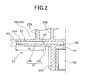
Fig. 2 is an enlarged cross-sectional view showing an intercommunication path designed in the form of a scroll; -
Fig. 3 is an enlarged cross-sectional view showing a state that a pin member is inserted into the intercommunication path; -
Fig. 4 is a cross-sectional view taken along IV-IV ofFig. 3 ; and -
Figs. 5A and 5B are diagrams showing another embodiment, whereinFig. 5A is a cross-sectional view, andFig. 5B is an enlarged view of a main part. - A preferred embodiment according to the present invention will be described hereunder with reference to the accompanying drawings.
- In
Fig. 1 ,reference numeral 1 represents a scroll type compressor having a high internal pressure. Thecompressor 1 is connected to a refrigerant circuit (not shown) in which refrigerant is circulated to perform a refrigeration cycle operation, and compresses the refrigerant. Thecompressor 1 has a hermetically-sealeddome type casing 3 which is designed in an elongated cylindrical shape. - The
casing 3 is constructed as a pressure container by a casingmain body 5 as a cylindrical body portion having an axis line in the up-and-down direction, a saucer-shapedupper cap 7 which is air-tightly welded and integrally joined to the upper end portion of the casingmain body 5 and has an upwardly projecting convex surface, and a saucer-shapedlower cap 7 having a downwardly projecting convex surface, and the inside of thecasing 3 is designed to have a cavity. - A
scroll compression mechanism 11 for compressing refrigerant, and adriving motor 13 disposed below thescroll compression mechanism 11 are mounted in thecasing 3. Thescroll compression mechanism 11 and he drivingmotor 13 are connected to each other through adriving shaft 15 which is disposed so as to extend in the up-and-down direction in thecasing 3. A gap space 17 is formed between thescroll compression mechanism 11 and thedriving motor 13. - The
scroll compression mechanism 11 has ahousing 21 as a substantially cylindrical accommodating member which is opened at the upper side thereof and has a bottom, afixed scroll 23 which is disposed in close contact with the upper surface of thehousing 21, and amovable scroll 25 which is disposed between thefixed scroll 23 and thehousing 21 and engaged with thefixed scroll 23. Thehousing 21 is press-fitted in the casingmain body 5 over the whole outer peripheral surface thereof in the peripheral direction. The inside of thecasing 3 is compartmented into a high pressure space 27 at the lower side of thehousing 21 and adischarge space 29 at the upper side of thehousing 21, and therespective spaces 27 and 29 intercommunicate with each other through a longitudinal groove (passage ) 71 which is formed on the outer peripheries of thehousing 21 and thefixed scroll 23 so as to extend longitudinally. - The
housing 21 is provided with ahousing space 21A in which an eccentricaxial portion 15A of thedriving shaft 15 is rotated, and a radial bearingportion 21B extending downwardly from the center of the lower surface of thehousing 21. Furthermore, thehousing 21 is provided with a radial bearinghole 28 penetrating between the lower end surface of the radial bearingportion 21B and the bottom surface of thehousing space 21A, and the upper end portion of the drivingshaft 15 is rotatably fitted and mounted through the radial bearing 3 0 in the radial bearinghole 28. Asuction pipe 31 for leading the refrigerant in the refrigerant circuit to thescroll compression mechanism 11 penetrates through theupper cap 7 of thecasing 3 and is air-tightly fixed to theupper cap 7, and adischarge pipe 33 for discharging the refrigerant in thecasing 3 to the outside of thecasing 3 penetrates through the casingmain body 5 and is air-tightly fixed to the casingmain body 5. Thesuction pipe 31 extends in the up-and-down direction in thedischarge space 29, and the inner end portion of thesuction pipe 31 penetrates through a suction port 32 opened to thefixed scroll 23 of thescroll compression mechanism 11, and intercommunicates with thecompression chamber 35. Accordingly, the refrigerant is sucked into thecompression chamber 35 through thesuction pipe 31. - The
driving motor 13 has an annular stator 37 fixed to the inner wall surface of thecasing 3, and arotor 39 which is freely rotatably provided inside the stator 37, themotor 13 is constructed by a DC motor, and themovable scroll 25 of thescroll compression mechanism 11 is connected to therotor 39 through thedriving shaft 15. - The
lower space 40 at the lower side of the drivingmotor 13 is kept to a high-pressure state, and oil is stocked at the inner bottom portion of thelower cap 9 corresponding to the lower end portion of thelower space 40. Anoil supply path 41 as a part of a high-pressure oil supply unit is formed in thedriving shaft 15, theoil supply path 41 intercommunicates with anoil chamber 43 at the back side of themovable scroll 25. A pickup 45 is connected to the lower end of thedriving shaft 15, and the pickup 45 scoops up the oil stocked at the inner bottom portion of thelower cap 9. The scooped oil is passed through theoil supply path 41 of thedriving shaft 15 and supplied to theoil chamber 43 at the back side of themovable scroll 25, and supplied from theoil chamber 43 to each sliding portion and thecompression chamber 35 of thescroll compression mechanism 11 through anintercommunication path 51 provided to themovable scroll 25. - The
fixed scroll 23 comprises amirror plate 23A and a scroll-like (involute type) lap 23b formed on the lower surface of themirror plate 23A. Themovable scroll 25 comprises amirror plate 25A and a scroll-type (involute type)lap 25B formed on the upper surface of themirror plate 25A. Thelap 23B of thefixed scroll 23 and thelap 25B of themovable scroll 25 are engaged with each other, wherebyplural compression chambers 35 are formed by both thelaps fixed scroll 23 and themovable scroll 25. - The
movable scroll 25 is supported through the Oldham'sring 61 by thefixed scroll 23, and acylindrical boss portion 25C having a bottom is projected from the center portion of the lower surface of themirror plate 25A. Furthermore, aneccentric shaft portion 15A is provided to the upper end of thedriving shaft 15, and theeccentric shaft portion 15A is rotatably fitted in theboss portion 25C of themovable scroll 25. - Furthermore, a
counter weight portion 63 is provided to the drivingshaft 15 at the lower side of theradial bearing portion 21B of thehousing 21 in order to establish dynamic balance with themovable scroll 25, theeccentric shaft portion 15A, etc.. The drivingshaft 15 rotates while keeping the weight balance by thecounter weight portion 63, whereby themovable scroll 25 does not rotate on its axis, but swirls. thecompression chamber 35 is configured so that in connection with the swirling of themovable scroll 25, the refrigerant sucked by thesuction pipe 31 is compressed due to contraction of the volume between both thelaps - A
discharge hole 73 is provided at the center portion of the fixedscroll 23, and gas refrigerant discharged from thedischarge hole 73 is passed through thedischarge valve 75 and discharged to thedischarge space 29, and flows out into the high-pressure space 27 at the lower side of thehousing 21 through alongitudinal groove 71 formed on the respective outer peripheries of thehousing 21 and the fixedscroll 23. This high-pressure refrigerant is discharged to the outside of thecasing 3 through thedischarge pipe 33 provided to the casingmain body 5. - A guide member (gas flow deflecting member) 77 is provided to the lower side of the
longitudinal groove 71. The guide member 77 deflects the flow direction of the gas refrigerant (which is discharged from thedischarge valve 75 to thedischarge space 29, passed through thelongitudinal groove 71 and flows downwardly) toward a shielding plate 79 and/or in the horizontal direction along the inner surface of the casing main body 5 (casing 3), and also guides the gas refrigerant through a passage between the shielding plate 79 at the upper side of the coil end 81 of the drivingmotor 13 and the inner surface of the casing main body 5 (casing 3) and then to thedischarge pipe 33. - The driving operation of the
scroll type compressor 1 described above will be described. - When the
drivingmotor 13 is driven, therotor 39 rotates relative to the stator 37, and thus the drivingshaft 15 rotates. When the drivingshaft 15 rotates, themovable scroll 25 of thescroll compression mechanism 11 does not rotate on its axis, but makes only the swirling motion relative to the fixedscroll 23. Accordingly, low-pressure refrigerant is passed through thesuction pipe 31, and sucked from the peripheral edge side of thecompression chamber 35 into thecompression chamber 35, so that this refrigerant is compressed in connection with volume variation of thecompression chamber 35. The compressed refrigerant is increased in pressure, passed from thecompression chamber 35 to thedischarge valve 75, and discharged to thedischarge space 29. Further, the refrigerant is passed through thelongitudinal groove 71 formed on the respective outer peripheries of thehousing 21 and the fixedscroll 23, and then flows out to the high-pressure space at the lower side of thehousing 21. Still further, this high-pressure refrigerant is discharged through thedischarge pipe 33 provided to the casingmain body 5 to the outside of thecasing 3. After the refrigerant discharged to the outside of thecasing 3 is circulated in the refrigerant circuit (not shown), the refrigerant is sucked through thesuction pipe 31 into thecompressor 1 again, and compressed in the compressor. The circulation of the refrigerant as described above is repeated. - The flow of oil will be described. Oil stocked in the inner bottom portion of the lower cap of the
casing 3 is scooped up by the pickup 45 provided to the lower end of the drivingshaft 15, and this oil is passed through anoil path 41 of the drivingshaft 15, supplied to anoil chamber 43 at the back side of themovable scroll 25, and then supplied from theoil chamber 43 through anintercommunication path 51 provided to themovable scroll 25 to each of sliding portions of thescroll compressor mechanism 11 and thecompression chamber 35. -
Fig. 2 is an enlarged view of theintercommunication path 51 provided to themovable scroll 25. - The mirror plate 2 5A of the
movable scroll 25 is provided with theintercommunication path 51 which is opened outwardly at one end thereof and extends linearly (in a radial direction of the movable scroll 25) inwardly. Theintercommunication path 51 is constructed by first forming alower hole 51A of an intercommunication path whose one end is opened outwardly and conducting reaming processing from one end to a position of a predetermined depth H in thelower hole 51A to form aninsertion hole 51B which extends to the predetermined depth H and has a surface roughness lower (i.e., higher smoothness) than thelower hole 51A. Accordingly, a minute step portion (stopper portion) 52 is formed at the rear end of theinsertion hole 51B, that is, the boundary between theinsertion hole 51B and thelower hole 51A. Furthermore, afemale screw hole 51C is formed at an inlet port of theinsertion hole 51B. The other end (high-pressure opening) of theintercommunication path 51 is bent in a substantially L-shape, and intercommunicates with the oil chamber (the high-pressure portion in the hermetically-sealed container) 43 at the backside of themovable scroll 25 described above. A low-pressure opening 53 is opened in the inner peripheral surface at the entrance side of theintercommunication path 51. The low-pressure opening 53 intercommunicates with the compression chamber (low-pressure portion 35A) at the outside which is formed between both thelaps scrolls -
Fig. 3 shows a state that a flow rate restricting member (pin member) 55 is inserted into theintercommunication path 51. - The
pin member 55 is formed by merely cutting a cylindrical pin element, and thepin member 55 is inserted from one end side of theinsertion hole 51B into theintercommunication path 51 till it comes into contact with thestopper portion 52 in theintercommunication path 51. Ascrew member 57 having a hexagon socket is threadedly inserted in thefemale screw hole 51C provided to one end of theinsertion hole 51B so as to be spaced from thepin member 55 at a predetermined interval h so that thepin member 55 is freely movable in the axial direction. Thisscrew member 57 closes one end of theinsertion hole 51B. Furthermore, thescrew member 57 is fixed by adhesive agent or the like so that it does not come loose. -
Fig. 4 is a cross-sectional view taken along IV-IV ofFig. 3 . - As described above, the
pin member 55 is freely movable in the axial direction by the amount corresponding to only the predetermined interval h. When high pressure is applied to the high-pressure opening 51D, thepin member 55 moves in the axial direction in theinsertion hole 51B, and thepin member 55 sags (bows) due to the pressure difference between the high-pressure portion and the low-pressure portion. Therefore, thepin member 55 is sucked to the low-pressure opening 53 side opened to the low-pressure portion in the scroll and sags (bows) upwardly as indicated by an arrow A inFig. 4 . Therefore, the pore space of the low-pressure opening 53 is restricted, and the restricted pore space of the low-pressure opening 53 regulates the supply amount (flow rate) of lubricating oil. That is, the supply amount (flow rate) of lubricating oil from the high pressure portion in the hermetically sealed container to the low-pressure portion in the scroll is regulated on the basis of the pressure difference between the high pressure portion and the low pressure portion. - In this construction, the gap between the outer periphery of the
pin member 55 and the low-pressure opening 53 opened to the low-pressure portion can be adjusted by properly regulating the size H of the low-pressure opening 53, so that the restriction (regulation) of the supply of lubricating oil can be managed with high precision. - Furthermore, since the
pin member 55 is freely movable in the axial direction by the amount corresponding to only the predetermined interval h, fixation of thepin member 55 is prevented, the attitude of thepin member 55 in theinsertion hole 51B is properly kept, and thepin member 55 is properly sucked to the low-pressure opening 53. Accordingly, the size of the gap between the outer periphery of thepin member 55 and the low-pressure opening 53 opened to the low pressure portion is kept substantially constant, whereby the restriction of the supply of the lubricating oil can be also managed with high precision. - Still furthermore, according to the above construction, it is unnecessary to subject the
pin member 55 to processing. Therefore, when the original shape of the pin member is cylindrical, the pin member can be directly used without modifying the shape. Therefore, it is not dependent on the processing precision, and also the manufacturing cost of thepin member 55 can be reduced. - The
stopper portion 52 is formed by thestep portion 52 between thelower hole 51A and theinsertion hole 51B, and thus thestopper portion 52 can be simply formed. - The reaming processing is conducted from one end of the
lower hole 51A till the position of the predetermined depth H of thelower hole 51A, so that the finishing precision of the inner peripheral surface of theinsertion hole 51B is enhanced, and the size of the gap between the outer periphery of thepin member 55 and the inner periphery of theintercommunication path 51, and the size of the gap between the outer periphery of thepin member 55 and the low-pressure opening 53 opened to the low-pressure portion can be managed with high precision. -
Figs. 5A and 5B show another embodiment. - In
Fig. 5A ,reference numeral 101 represents a scroll type compressor which is internally set to low pressure, and thiscompressor 101 has a longitudinal cylindrical hermetically-sealeddome type casing 103. - The
casing 103 is constructed as a pressure container by a casingmain body 105 as a cylindrical body portion having an axial line extending in the up-and-down direction, anupper cap 107 which is air-tightly welded to the upper end portion of the casingmain body 105, and alower cap 109 which is air-tightly welded to the lower end portion of the casingmain body 5, and the inside thereof is designed as a cavity. - A scroll compression mechanism 111 and a driving
motor 113 are accommodated in thecasing 103.Reference numeral 115 represents a driving shaft, and agap space 117 is formed between the scroll compression mechanism 111 and the drivingmotor 113. - The scroll compression mechanism 111 has a
housing 121, afixed scroll 123 and a movable scroll 125, and the outer peripheral surface of thehousing 1 is press-fitted and fixed over the whole surface in the peripheral direction into the casingmain body 105, and air-tightly brought into contact with the casingmain body 105. - Furthermore, the inside of the
casing 103 is compartmented into a low-pressure space at the lower side of thehousing 121 and a high-pressure space at the upper side of thehousing 21. Furthermore, asuction pipe 131 for leading refrigerant in the refrigerant circuit to the scroll compression mechanism 111 air-tightly penetrates through the lower portion of the casingmain body 105 and is fixed to the lower portion of the casingmain body 105, and adischarge pipe 133 for discharging refrigerant in thecasing 103 to the outside of the casing 103 air-tightly penetrates through theupper cap 107 and is fixed to theupper cap 107. - The driving
motor 113 has anannular stator 137 and arotor 139, and the movable scroll 125 of the scroll compression mechanism 111 is connected to therotor 139 through the drivingshaft 115. Thelower space 140 at the lower side of the drivingmotor 113 is kept to low pressure, and oil is stocked at the inner bottom portion of thelower cap 109 which corresponds to the lower end portion of thelower space 140. Anoil supply path 141 as a part of an oil supply unit is formed in the drivingshaft axis 115, and theoil supply path 141 intercommunicates with anoil chamber 143 at the back side of the movable scroll 125. - In this embodiment, as shown in
Fig. 5B , anintercommunication path 151 which is opened to the outside of amirror plate 123A of the fixedscroll 123 at one end thereof and extends linearly (in a radial direction of the fixed roller) inside themirror plate 123A is formed in themirror plate 123A of the fixedscroll 123. Theintercommunication path 151 is constructed by first forming alower hole 151A of the intercommunication path whose one end is opened to the outside, and then conducting reaming processing from one end of thelower hole 151A to form aninsertion hole 151B having a low surface roughness (i.e., high smoothness). Furthermore, afemale screw hole 151 is threaded in the inlet port of theinsertion hole 151B. The other end (low-pressure opening) 151D of theintercommunication path 151 intercommunicates with a compression chamber 135 (low pressure portion 135A) formed between both thelaps scrolls 123 and 125 through aslender hole 152. Furthermore, one end side of theintercommunication path 151 intercommunicates with thehigh pressure space 129 described above through a slender hole (high pressure opening) 154. The upper end of theslender hole 154 is opened to arecess place 123C as an oil pool formed on the upper surface of the fixedscroll 123. - A flow rate restricting member (pin member) 155 is inserted in the
intercommunication path 151, and ascrew member 157 is threaded in afemale screw hole 151C provided to one end of theinsertion hole 151B so as to be spaced from thepin member 155 at a predetermined interval h so that thepin member 155 is freely movable in the axial direction. Thisscrew member 157 closes one end of theinsertion hole 151B. - As described above, the
pin member 155 is freelymovable in the axial direction by the amount corresponding to the predetermined interval h. When high pressure is imposed on the high-pressure space 129, thepin member 155 is pressed by the oil to move to the right side in the axial direction in theinsertion hole 151B. At the same time, thepin member 155 sags due to the pressure difference between the high pressure portion and the low pressure portion, and thus thepin member 155 is sucked to the low-pressure opening 151D side opened to the low pressure portion in the scroll by the same phenomenon indicated by the arrow A inFig. 4 , whereby the interval of the low-pressure opening 151D is regulated. This interval restricts the supply amount of the lubricating oil. - In this construction, by properly defining the size of the low-
pressure opening 151D, the size of the gap between the outer periphery of thepin member 155 and the low-pressure opening 151D opened to the low pressure portion is adjusted, so that the restriction of the supply of the lubricating oil can be managed with high precision. - Furthermore, since the
pin member 155 is freely movable in the axial direction by only the predetermined interval h. Therefore, fixation of thepin member 155 is avoided, and the attitude of thepin member 15 in theinsertion hole 151B is properly kept, and thepin member 155 is properly sucked to the low-pressure opening 151D. Accordingly, the size of the gap between the outer periphery of thepin member 155 and the low-pressure opening 151D opened to the low pressure portion is kept substantially constant, whereby restriction (regulation) of the supply of the lubricating oil can be also managed with high precision. - Still furthermore, according to this construction, it is unnecessary to subject the
pin member 155 to processing, and when the original shape of the pin member is cylindrical, the pin member can be directly used without modifying the shape. Therefore, it is not dependent on the processing precision, and also the manufacturing cost of thepin member 155 can be reduced.
Claims (4)
- A scroll type compressor comprising:a fixed scroll;a movable scroll engaged with the fixed scroll; anda hermetically sealed container in which the fixed scroll and the movable scroll are mounted, wherein one scroll of the fixed scroll and the movable scroll is provided with an intercommunication path that is opened to the outside of the one scroll at one end thereof, extends substantially in a radial direction of the one scroll and has a high-pressure opening intercommunicating with a high-pressure portion of the hermetically sealed container and a low-pressure opening intercommunicating with a low-pressure portion in the one scroll, oil being supplied from the high-pressure opening through the inside of the intercommunication path to the low-pressure opening, a pin member that is configured to be slightly smaller in diameter than the intercommunication path and disposed in the intercommunication path so as to be movable in the radial direction of the one scroll by a predetermined distance, a screw member that is provided at one end of the intercommunication path so as to close the one end and is disposed so as to be spaced from the pin member at a predetermined interval, and a stopper that is provided at a predetermined position in the intercommunication path and regulates movement of the pin member in the radial direction so that the pin member is radially movable between the screw member and the stopper.
- The scroll type compressor according to claim 1, wherein the intercommunication path has a linearly extending portion in the movable scroll.
- The scroll type compressor according to claim 1, wherein the intercommunication path has a first path opened to the outside of the one scroll at one end thereof, and a second path that is formed by subjecting the first path to reaming processing until a predetermined depth position of the first path so that a step portion serving as the stopper is formed between the first path and the second path, the pin member being inserted in the second path.
- The scroll type compressor according to claim 1, wherein the pin member is sucked to the low-pressure opening opened to the low pressure portion due to a pressure difference between the highpressure portion and the low pressure portion to thereby restrict the gap between the outer periphery of the pin member and the low-pressure opening opened to the low-pressure portion. Accordingly, when the original shape of the pin member is cylindrical, the pin member can be directly used without modifying the shape. Therefore, it is not dependent on the processing precision, and also the manufacturing cost of the pin member 55 can be reduced.
Applications Claiming Priority (1)
| Application Number | Priority Date | Filing Date | Title |
|---|---|---|---|
| JP2009037444A JP2010190167A (en) | 2009-02-20 | 2009-02-20 | Scroll compressor |
Publications (3)
| Publication Number | Publication Date |
|---|---|
| EP2221479A2 true EP2221479A2 (en) | 2010-08-25 |
| EP2221479A3 EP2221479A3 (en) | 2016-11-02 |
| EP2221479B1 EP2221479B1 (en) | 2017-11-01 |
Family
ID=42045418
Family Applications (1)
| Application Number | Title | Priority Date | Filing Date |
|---|---|---|---|
| EP10001632.8A Not-in-force EP2221479B1 (en) | 2009-02-20 | 2010-02-17 | Scroll type compressor |
Country Status (5)
| Country | Link |
|---|---|
| US (1) | US8585381B2 (en) |
| EP (1) | EP2221479B1 (en) |
| JP (1) | JP2010190167A (en) |
| KR (1) | KR101099923B1 (en) |
| CN (1) | CN101813088A (en) |
Cited By (2)
| Publication number | Priority date | Publication date | Assignee | Title |
|---|---|---|---|---|
| EP2574791A3 (en) * | 2011-09-28 | 2016-06-22 | LG Electronics, Inc. | Scroll compressor |
| EP3385538A4 (en) * | 2015-12-28 | 2019-05-29 | Daikin Industries, Ltd. | VOLUTE COMPRESSOR |
Families Citing this family (10)
| Publication number | Priority date | Publication date | Assignee | Title |
|---|---|---|---|---|
| FR2969226B1 (en) | 2010-12-16 | 2013-01-11 | Danfoss Commercial Compressors | SPIRAL REFRIGERATING COMPRESSOR |
| FR2969228B1 (en) | 2010-12-16 | 2016-02-19 | Danfoss Commercial Compressors | SPIRAL REFRIGERATING COMPRESSOR |
| KR101810461B1 (en) * | 2011-03-24 | 2017-12-19 | 엘지전자 주식회사 | Scroll compressor |
| WO2014206334A1 (en) | 2013-06-27 | 2014-12-31 | Emerson Climate Technologies, Inc. | Scroll compressor with oil management system |
| KR101971819B1 (en) | 2015-04-30 | 2019-04-23 | 에머슨 클라이미트 테크놀로지스 (쑤저우) 코., 엘티디. | Scroll compressor |
| KR20180091577A (en) | 2017-02-07 | 2018-08-16 | 엘지전자 주식회사 | Scroll compressor |
| JP7000136B2 (en) | 2017-11-29 | 2022-01-19 | 三菱重工サーマルシステムズ株式会社 | Scroll compressor |
| KR102009908B1 (en) * | 2018-05-15 | 2019-08-14 | 김범열 | Helical gear pump |
| KR102454721B1 (en) * | 2021-02-19 | 2022-10-14 | 엘지전자 주식회사 | Scroll Compressor |
| CN120752437A (en) * | 2023-03-30 | 2025-10-03 | 萨姆压缩机工业有限公司 | compressor |
Citations (1)
| Publication number | Priority date | Publication date | Assignee | Title |
|---|---|---|---|---|
| JP2004060532A (en) | 2002-07-29 | 2004-02-26 | Daikin Ind Ltd | Compressor |
Family Cites Families (26)
| Publication number | Priority date | Publication date | Assignee | Title |
|---|---|---|---|---|
| DE2352965A1 (en) * | 1973-10-23 | 1975-04-30 | Bosch Gmbh Robert | ARRANGEMENT FOR EXHAUST GAS DETOXIFICATION FROM COMBUSTION MACHINES |
| JPS5073025U (en) * | 1973-11-06 | 1975-06-26 | ||
| JPS58176486A (en) * | 1982-04-09 | 1983-10-15 | Hitachi Ltd | Enclosed type motor compressor |
| JPS60206989A (en) * | 1984-03-30 | 1985-10-18 | Mitsubishi Electric Corp | Scroll type fluid machine |
| JPH0733829B2 (en) * | 1986-02-03 | 1995-04-12 | 松下電器産業株式会社 | Scroll compressor |
| JPH01163484A (en) * | 1987-12-19 | 1989-06-27 | Tokico Ltd | oil-cooled scroll compressor |
| JPH01300080A (en) * | 1988-05-30 | 1989-12-04 | Matsushita Refrig Co Ltd | Scroll compressor |
| JP2600400B2 (en) * | 1989-11-02 | 1997-04-16 | 松下電器産業株式会社 | Scroll compressor |
| EP0469700B1 (en) * | 1990-07-31 | 1996-07-24 | Copeland Corporation | Scroll machine lubrication system |
| EP0518356B1 (en) * | 1991-06-13 | 1995-05-10 | Daikin Industries, Limited | Scroll type fluid machine |
| US5511831A (en) * | 1993-01-04 | 1996-04-30 | Modine Manufacturing Company | Self-centering, self-seating, double-sealing, interference fit tube joint |
| JPH10196572A (en) * | 1997-01-07 | 1998-07-31 | Matsushita Electric Ind Co Ltd | Hermetic compressor |
| JPH1163484A (en) | 1997-08-20 | 1999-03-05 | Matsushita Electric Ind Co Ltd | Combustion control device |
| US6203299B1 (en) * | 1998-12-21 | 2001-03-20 | Scroll Technologies | Capacity modulation for scroll compressors |
| JP3873574B2 (en) * | 2000-04-27 | 2007-01-24 | 松下電器産業株式会社 | Processing method of compression mechanism parts |
| JP2002168183A (en) * | 2000-12-04 | 2002-06-14 | Matsushita Electric Ind Co Ltd | Scroll compressor |
| JP2003042080A (en) * | 2001-07-31 | 2003-02-13 | Matsushita Electric Ind Co Ltd | Hermetic scroll compressor |
| JP3925229B2 (en) | 2002-02-14 | 2007-06-06 | 松下電器産業株式会社 | Hermetic scroll compressor, refrigeration cycle and refrigeration apparatus using the same |
| KR100924895B1 (en) * | 2002-05-24 | 2009-11-02 | 파나소닉 주식회사 | Scroll compressor |
| US6761545B1 (en) * | 2002-12-31 | 2004-07-13 | Scroll Technologies | Scroll compressor with flow restriction and back pressure chamber tap |
| JP3842222B2 (en) * | 2003-01-21 | 2006-11-08 | 株式会社オティックス | Manufacturing method of common rail |
| JP4727157B2 (en) * | 2004-02-27 | 2011-07-20 | 三菱重工業株式会社 | Scroll compressor |
| JP4470636B2 (en) * | 2004-08-04 | 2010-06-02 | ダイキン工業株式会社 | Scroll type fluid machine |
| JP2006307803A (en) * | 2005-05-02 | 2006-11-09 | Sanden Corp | Scroll compressor |
| SE530058C2 (en) * | 2005-12-23 | 2008-02-19 | Dustcontrol Internat Ab | piping systems |
| JP2007285304A (en) * | 2007-08-06 | 2007-11-01 | ▲荒▼田 哲哉 | Method for lubricating working chamber of scroll fluid machine |
-
2009
- 2009-02-20 JP JP2009037444A patent/JP2010190167A/en active Pending
- 2009-12-14 KR KR1020090124060A patent/KR101099923B1/en active Active
-
2010
- 2010-02-11 CN CN201010121458A patent/CN101813088A/en active Pending
- 2010-02-17 EP EP10001632.8A patent/EP2221479B1/en not_active Not-in-force
- 2010-02-19 US US12/709,100 patent/US8585381B2/en not_active Expired - Fee Related
Patent Citations (1)
| Publication number | Priority date | Publication date | Assignee | Title |
|---|---|---|---|---|
| JP2004060532A (en) | 2002-07-29 | 2004-02-26 | Daikin Ind Ltd | Compressor |
Cited By (2)
| Publication number | Priority date | Publication date | Assignee | Title |
|---|---|---|---|---|
| EP2574791A3 (en) * | 2011-09-28 | 2016-06-22 | LG Electronics, Inc. | Scroll compressor |
| EP3385538A4 (en) * | 2015-12-28 | 2019-05-29 | Daikin Industries, Ltd. | VOLUTE COMPRESSOR |
Also Published As
| Publication number | Publication date |
|---|---|
| US20100215535A1 (en) | 2010-08-26 |
| EP2221479A3 (en) | 2016-11-02 |
| US8585381B2 (en) | 2013-11-19 |
| EP2221479B1 (en) | 2017-11-01 |
| KR20100095361A (en) | 2010-08-30 |
| CN101813088A (en) | 2010-08-25 |
| KR101099923B1 (en) | 2011-12-28 |
| JP2010190167A (en) | 2010-09-02 |
Similar Documents
| Publication | Publication Date | Title |
|---|---|---|
| EP2221479B1 (en) | Scroll type compressor | |
| US9850904B2 (en) | Scroll compressor | |
| JP6344574B2 (en) | Scroll compressor | |
| US20130216416A1 (en) | Scroll Compressor | |
| CN104105878A (en) | Compressor | |
| CN103502646B (en) | Scroll compressor | |
| EP2910785A1 (en) | Scroll compressor | |
| CN101900115A (en) | scroll compressor | |
| CN202510366U (en) | Scroll compressor | |
| JP6555543B2 (en) | Scroll compressor | |
| EP2221480B1 (en) | Scroll type compressor | |
| WO2017158665A1 (en) | Scroll compressor | |
| WO2019163516A1 (en) | Scroll fluid machine | |
| CN110998094A (en) | scroll compressor | |
| US11333147B2 (en) | Scroll compressor including an orbiting scroll having an orbiting end plate provided with a rear concave portion | |
| JP2002364564A (en) | Scroll fluid machine | |
| EP3339647A1 (en) | Compressor | |
| CN105443378B (en) | Scroll compressor and air conditioner | |
| JP2021021345A (en) | Scroll-type compressor | |
| EP3385538A1 (en) | Scroll compressor | |
| JP2884907B2 (en) | Scroll compressor | |
| WO2019163537A1 (en) | Scroll fluid machine | |
| JP5097369B2 (en) | Hermetic scroll compressor | |
| CN106662105A (en) | Scroll compressor | |
| WO2018021058A1 (en) | Scroll compressor |
Legal Events
| Date | Code | Title | Description |
|---|---|---|---|
| PUAI | Public reference made under article 153(3) epc to a published international application that has entered the european phase |
Free format text: ORIGINAL CODE: 0009012 |
|
| 17P | Request for examination filed |
Effective date: 20100217 |
|
| AK | Designated contracting states |
Kind code of ref document: A2 Designated state(s): AT BE BG CH CY CZ DE DK EE ES FI FR GB GR HR HU IE IS IT LI LT LU LV MC MK MT NL NO PL PT RO SE SI SK SM TR |
|
| AX | Request for extension of the european patent |
Extension state: AL BA RS |
|
| PUAL | Search report despatched |
Free format text: ORIGINAL CODE: 0009013 |
|
| RIC1 | Information provided on ipc code assigned before grant |
Ipc: F04C 18/02 20060101AFI20160922BHEP Ipc: F04C 29/02 20060101ALI20160922BHEP Ipc: F04C 23/00 20060101ALI20160922BHEP |
|
| AK | Designated contracting states |
Kind code of ref document: A3 Designated state(s): AT BE BG CH CY CZ DE DK EE ES FI FR GB GR HR HU IE IS IT LI LT LU LV MC MK MT NL NO PL PT RO SE SI SK SM TR |
|
| AX | Request for extension of the european patent |
Extension state: AL BA RS |
|
| RBV | Designated contracting states (corrected) |
Designated state(s): AT BE BG CH CY CZ DE DK EE ES FI FR GB GR HR HU IE IS IT LI LT LU LV MC MK MT NL NO PL PT RO SE SI SK SM TR |
|
| GRAP | Despatch of communication of intention to grant a patent |
Free format text: ORIGINAL CODE: EPIDOSNIGR1 |
|
| STAA | Information on the status of an ep patent application or granted ep patent |
Free format text: STATUS: GRANT OF PATENT IS INTENDED |
|
| INTG | Intention to grant announced |
Effective date: 20170609 |
|
| GRAS | Grant fee paid |
Free format text: ORIGINAL CODE: EPIDOSNIGR3 |
|
| GRAA | (expected) grant |
Free format text: ORIGINAL CODE: 0009210 |
|
| STAA | Information on the status of an ep patent application or granted ep patent |
Free format text: STATUS: THE PATENT HAS BEEN GRANTED |
|
| AK | Designated contracting states |
Kind code of ref document: B1 Designated state(s): AT BE BG CH CY CZ DE DK EE ES FI FR GB GR HR HU IE IS IT LI LT LU LV MC MK MT NL NO PL PT RO SE SI SK SM TR |
|
| REG | Reference to a national code |
Ref country code: GB Ref legal event code: FG4D |
|
| REG | Reference to a national code |
Ref country code: CH Ref legal event code: EP Ref country code: AT Ref legal event code: REF Ref document number: 942316 Country of ref document: AT Kind code of ref document: T Effective date: 20171115 |
|
| REG | Reference to a national code |
Ref country code: IE Ref legal event code: FG4D |
|
| REG | Reference to a national code |
Ref country code: DE Ref legal event code: R096 Ref document number: 602010046317 Country of ref document: DE |
|
| REG | Reference to a national code |
Ref country code: NL Ref legal event code: MP Effective date: 20171101 |
|
| REG | Reference to a national code |
Ref country code: LT Ref legal event code: MG4D |
|
| REG | Reference to a national code |
Ref country code: AT Ref legal event code: MK05 Ref document number: 942316 Country of ref document: AT Kind code of ref document: T Effective date: 20171101 |
|
| PG25 | Lapsed in a contracting state [announced via postgrant information from national office to epo] |
Ref country code: LT Free format text: LAPSE BECAUSE OF FAILURE TO SUBMIT A TRANSLATION OF THE DESCRIPTION OR TO PAY THE FEE WITHIN THE PRESCRIBED TIME-LIMIT Effective date: 20171101 Ref country code: ES Free format text: LAPSE BECAUSE OF FAILURE TO SUBMIT A TRANSLATION OF THE DESCRIPTION OR TO PAY THE FEE WITHIN THE PRESCRIBED TIME-LIMIT Effective date: 20171101 Ref country code: NL Free format text: LAPSE BECAUSE OF FAILURE TO SUBMIT A TRANSLATION OF THE DESCRIPTION OR TO PAY THE FEE WITHIN THE PRESCRIBED TIME-LIMIT Effective date: 20171101 Ref country code: NO Free format text: LAPSE BECAUSE OF FAILURE TO SUBMIT A TRANSLATION OF THE DESCRIPTION OR TO PAY THE FEE WITHIN THE PRESCRIBED TIME-LIMIT Effective date: 20180201 Ref country code: SE Free format text: LAPSE BECAUSE OF FAILURE TO SUBMIT A TRANSLATION OF THE DESCRIPTION OR TO PAY THE FEE WITHIN THE PRESCRIBED TIME-LIMIT Effective date: 20171101 Ref country code: FI Free format text: LAPSE BECAUSE OF FAILURE TO SUBMIT A TRANSLATION OF THE DESCRIPTION OR TO PAY THE FEE WITHIN THE PRESCRIBED TIME-LIMIT Effective date: 20171101 |
|
| PG25 | Lapsed in a contracting state [announced via postgrant information from national office to epo] |
Ref country code: IS Free format text: LAPSE BECAUSE OF FAILURE TO SUBMIT A TRANSLATION OF THE DESCRIPTION OR TO PAY THE FEE WITHIN THE PRESCRIBED TIME-LIMIT Effective date: 20180301 Ref country code: HR Free format text: LAPSE BECAUSE OF FAILURE TO SUBMIT A TRANSLATION OF THE DESCRIPTION OR TO PAY THE FEE WITHIN THE PRESCRIBED TIME-LIMIT Effective date: 20171101 Ref country code: BG Free format text: LAPSE BECAUSE OF FAILURE TO SUBMIT A TRANSLATION OF THE DESCRIPTION OR TO PAY THE FEE WITHIN THE PRESCRIBED TIME-LIMIT Effective date: 20180201 Ref country code: LV Free format text: LAPSE BECAUSE OF FAILURE TO SUBMIT A TRANSLATION OF THE DESCRIPTION OR TO PAY THE FEE WITHIN THE PRESCRIBED TIME-LIMIT Effective date: 20171101 Ref country code: AT Free format text: LAPSE BECAUSE OF FAILURE TO SUBMIT A TRANSLATION OF THE DESCRIPTION OR TO PAY THE FEE WITHIN THE PRESCRIBED TIME-LIMIT Effective date: 20171101 Ref country code: GR Free format text: LAPSE BECAUSE OF FAILURE TO SUBMIT A TRANSLATION OF THE DESCRIPTION OR TO PAY THE FEE WITHIN THE PRESCRIBED TIME-LIMIT Effective date: 20180202 |
|
| PG25 | Lapsed in a contracting state [announced via postgrant information from national office to epo] |
Ref country code: CZ Free format text: LAPSE BECAUSE OF FAILURE TO SUBMIT A TRANSLATION OF THE DESCRIPTION OR TO PAY THE FEE WITHIN THE PRESCRIBED TIME-LIMIT Effective date: 20171101 Ref country code: SK Free format text: LAPSE BECAUSE OF FAILURE TO SUBMIT A TRANSLATION OF THE DESCRIPTION OR TO PAY THE FEE WITHIN THE PRESCRIBED TIME-LIMIT Effective date: 20171101 Ref country code: DK Free format text: LAPSE BECAUSE OF FAILURE TO SUBMIT A TRANSLATION OF THE DESCRIPTION OR TO PAY THE FEE WITHIN THE PRESCRIBED TIME-LIMIT Effective date: 20171101 Ref country code: EE Free format text: LAPSE BECAUSE OF FAILURE TO SUBMIT A TRANSLATION OF THE DESCRIPTION OR TO PAY THE FEE WITHIN THE PRESCRIBED TIME-LIMIT Effective date: 20171101 Ref country code: CY Free format text: LAPSE BECAUSE OF FAILURE TO SUBMIT A TRANSLATION OF THE DESCRIPTION OR TO PAY THE FEE WITHIN THE PRESCRIBED TIME-LIMIT Effective date: 20171101 |
|
| REG | Reference to a national code |
Ref country code: DE Ref legal event code: R097 Ref document number: 602010046317 Country of ref document: DE |
|
| PG25 | Lapsed in a contracting state [announced via postgrant information from national office to epo] |
Ref country code: IT Free format text: LAPSE BECAUSE OF FAILURE TO SUBMIT A TRANSLATION OF THE DESCRIPTION OR TO PAY THE FEE WITHIN THE PRESCRIBED TIME-LIMIT Effective date: 20171101 Ref country code: RO Free format text: LAPSE BECAUSE OF FAILURE TO SUBMIT A TRANSLATION OF THE DESCRIPTION OR TO PAY THE FEE WITHIN THE PRESCRIBED TIME-LIMIT Effective date: 20171101 Ref country code: PL Free format text: LAPSE BECAUSE OF FAILURE TO SUBMIT A TRANSLATION OF THE DESCRIPTION OR TO PAY THE FEE WITHIN THE PRESCRIBED TIME-LIMIT Effective date: 20171101 Ref country code: SM Free format text: LAPSE BECAUSE OF FAILURE TO SUBMIT A TRANSLATION OF THE DESCRIPTION OR TO PAY THE FEE WITHIN THE PRESCRIBED TIME-LIMIT Effective date: 20171101 |
|
| PLBE | No opposition filed within time limit |
Free format text: ORIGINAL CODE: 0009261 |
|
| STAA | Information on the status of an ep patent application or granted ep patent |
Free format text: STATUS: NO OPPOSITION FILED WITHIN TIME LIMIT |
|
| REG | Reference to a national code |
Ref country code: CH Ref legal event code: PL |
|
| PG25 | Lapsed in a contracting state [announced via postgrant information from national office to epo] |
Ref country code: MC Free format text: LAPSE BECAUSE OF FAILURE TO SUBMIT A TRANSLATION OF THE DESCRIPTION OR TO PAY THE FEE WITHIN THE PRESCRIBED TIME-LIMIT Effective date: 20171101 |
|
| 26N | No opposition filed |
Effective date: 20180802 |
|
| GBPC | Gb: european patent ceased through non-payment of renewal fee |
Effective date: 20180217 |
|
| REG | Reference to a national code |
Ref country code: IE Ref legal event code: MM4A |
|
| REG | Reference to a national code |
Ref country code: BE Ref legal event code: MM Effective date: 20180228 |
|
| PG25 | Lapsed in a contracting state [announced via postgrant information from national office to epo] |
Ref country code: SI Free format text: LAPSE BECAUSE OF FAILURE TO SUBMIT A TRANSLATION OF THE DESCRIPTION OR TO PAY THE FEE WITHIN THE PRESCRIBED TIME-LIMIT Effective date: 20171101 Ref country code: CH Free format text: LAPSE BECAUSE OF NON-PAYMENT OF DUE FEES Effective date: 20180228 Ref country code: LU Free format text: LAPSE BECAUSE OF NON-PAYMENT OF DUE FEES Effective date: 20180217 Ref country code: LI Free format text: LAPSE BECAUSE OF NON-PAYMENT OF DUE FEES Effective date: 20180228 |
|
| REG | Reference to a national code |
Ref country code: FR Ref legal event code: ST Effective date: 20181031 |
|
| PG25 | Lapsed in a contracting state [announced via postgrant information from national office to epo] |
Ref country code: IE Free format text: LAPSE BECAUSE OF NON-PAYMENT OF DUE FEES Effective date: 20180217 |
|
| PG25 | Lapsed in a contracting state [announced via postgrant information from national office to epo] |
Ref country code: GB Free format text: LAPSE BECAUSE OF NON-PAYMENT OF DUE FEES Effective date: 20180217 Ref country code: BE Free format text: LAPSE BECAUSE OF NON-PAYMENT OF DUE FEES Effective date: 20180228 Ref country code: FR Free format text: LAPSE BECAUSE OF NON-PAYMENT OF DUE FEES Effective date: 20180228 |
|
| PG25 | Lapsed in a contracting state [announced via postgrant information from national office to epo] |
Ref country code: MT Free format text: LAPSE BECAUSE OF NON-PAYMENT OF DUE FEES Effective date: 20180217 |
|
| PG25 | Lapsed in a contracting state [announced via postgrant information from national office to epo] |
Ref country code: TR Free format text: LAPSE BECAUSE OF FAILURE TO SUBMIT A TRANSLATION OF THE DESCRIPTION OR TO PAY THE FEE WITHIN THE PRESCRIBED TIME-LIMIT Effective date: 20171101 |
|
| PG25 | Lapsed in a contracting state [announced via postgrant information from national office to epo] |
Ref country code: PT Free format text: LAPSE BECAUSE OF FAILURE TO SUBMIT A TRANSLATION OF THE DESCRIPTION OR TO PAY THE FEE WITHIN THE PRESCRIBED TIME-LIMIT Effective date: 20171101 Ref country code: HU Free format text: LAPSE BECAUSE OF FAILURE TO SUBMIT A TRANSLATION OF THE DESCRIPTION OR TO PAY THE FEE WITHIN THE PRESCRIBED TIME-LIMIT; INVALID AB INITIO Effective date: 20100217 |
|
| PG25 | Lapsed in a contracting state [announced via postgrant information from national office to epo] |
Ref country code: MK Free format text: LAPSE BECAUSE OF NON-PAYMENT OF DUE FEES Effective date: 20171101 |
|
| PGFP | Annual fee paid to national office [announced via postgrant information from national office to epo] |
Ref country code: DE Payment date: 20240219 Year of fee payment: 15 |
|
| REG | Reference to a national code |
Ref country code: DE Ref legal event code: R119 Ref document number: 602010046317 Country of ref document: DE |
|
| PG25 | Lapsed in a contracting state [announced via postgrant information from national office to epo] |
Ref country code: DE Free format text: LAPSE BECAUSE OF NON-PAYMENT OF DUE FEES Effective date: 20250902 |