EP2221461A1 - Exhaust gas purifying apparatus - Google Patents
Exhaust gas purifying apparatus Download PDFInfo
- Publication number
- EP2221461A1 EP2221461A1 EP08849217A EP08849217A EP2221461A1 EP 2221461 A1 EP2221461 A1 EP 2221461A1 EP 08849217 A EP08849217 A EP 08849217A EP 08849217 A EP08849217 A EP 08849217A EP 2221461 A1 EP2221461 A1 EP 2221461A1
- Authority
- EP
- European Patent Office
- Prior art keywords
- catalytic
- carrier structure
- catalytic unit
- exhaust gas
- honeycomb carrier
- Prior art date
- Legal status (The legal status is an assumption and is not a legal conclusion. Google has not performed a legal analysis and makes no representation as to the accuracy of the status listed.)
- Granted
Links
Images


Classifications
-
- B—PERFORMING OPERATIONS; TRANSPORTING
- B01—PHYSICAL OR CHEMICAL PROCESSES OR APPARATUS IN GENERAL
- B01D—SEPARATION
- B01D53/00—Separation of gases or vapours; Recovering vapours of volatile solvents from gases; Chemical or biological purification of waste gases, e.g. engine exhaust gases, smoke, fumes, flue gases, aerosols
- B01D53/34—Chemical or biological purification of waste gases
- B01D53/92—Chemical or biological purification of waste gases of engine exhaust gases
- B01D53/94—Chemical or biological purification of waste gases of engine exhaust gases by catalytic processes
- B01D53/9445—Simultaneously removing carbon monoxide, hydrocarbons or nitrogen oxides making use of three-way catalysts [TWC] or four-way-catalysts [FWC]
- B01D53/945—Simultaneously removing carbon monoxide, hydrocarbons or nitrogen oxides making use of three-way catalysts [TWC] or four-way-catalysts [FWC] characterised by a specific catalyst
-
- B—PERFORMING OPERATIONS; TRANSPORTING
- B01—PHYSICAL OR CHEMICAL PROCESSES OR APPARATUS IN GENERAL
- B01J—CHEMICAL OR PHYSICAL PROCESSES, e.g. CATALYSIS OR COLLOID CHEMISTRY; THEIR RELEVANT APPARATUS
- B01J23/00—Catalysts comprising metals or metal oxides or hydroxides, not provided for in group B01J21/00
- B01J23/38—Catalysts comprising metals or metal oxides or hydroxides, not provided for in group B01J21/00 of noble metals
- B01J23/40—Catalysts comprising metals or metal oxides or hydroxides, not provided for in group B01J21/00 of noble metals of the platinum group metals
- B01J23/46—Ruthenium, rhodium, osmium or iridium
- B01J23/464—Rhodium
-
- B—PERFORMING OPERATIONS; TRANSPORTING
- B01—PHYSICAL OR CHEMICAL PROCESSES OR APPARATUS IN GENERAL
- B01J—CHEMICAL OR PHYSICAL PROCESSES, e.g. CATALYSIS OR COLLOID CHEMISTRY; THEIR RELEVANT APPARATUS
- B01J35/00—Catalysts, in general, characterised by their form or physical properties
- B01J35/19—Catalysts containing parts with different compositions
-
- B—PERFORMING OPERATIONS; TRANSPORTING
- B01—PHYSICAL OR CHEMICAL PROCESSES OR APPARATUS IN GENERAL
- B01J—CHEMICAL OR PHYSICAL PROCESSES, e.g. CATALYSIS OR COLLOID CHEMISTRY; THEIR RELEVANT APPARATUS
- B01J35/00—Catalysts, in general, characterised by their form or physical properties
- B01J35/50—Catalysts, in general, characterised by their form or physical properties characterised by their shape or configuration
- B01J35/56—Foraminous structures having flow-through passages or channels, e.g. grids or three-dimensional [3D] monoliths
-
- F—MECHANICAL ENGINEERING; LIGHTING; HEATING; WEAPONS; BLASTING
- F01—MACHINES OR ENGINES IN GENERAL; ENGINE PLANTS IN GENERAL; STEAM ENGINES
- F01N—GAS-FLOW SILENCERS OR EXHAUST APPARATUS FOR MACHINES OR ENGINES IN GENERAL; GAS-FLOW SILENCERS OR EXHAUST APPARATUS FOR INTERNAL-COMBUSTION ENGINES
- F01N13/00—Exhaust or silencing apparatus characterised by constructional features
- F01N13/04—Exhaust or silencing apparatus characterised by constructional features having two or more silencers in parallel, e.g. having interconnections for multi-cylinder engines
-
- F—MECHANICAL ENGINEERING; LIGHTING; HEATING; WEAPONS; BLASTING
- F01—MACHINES OR ENGINES IN GENERAL; ENGINE PLANTS IN GENERAL; STEAM ENGINES
- F01N—GAS-FLOW SILENCERS OR EXHAUST APPARATUS FOR MACHINES OR ENGINES IN GENERAL; GAS-FLOW SILENCERS OR EXHAUST APPARATUS FOR INTERNAL-COMBUSTION ENGINES
- F01N13/00—Exhaust or silencing apparatus characterised by constructional features
- F01N13/08—Other arrangements or adaptations of exhaust conduits
- F01N13/10—Other arrangements or adaptations of exhaust conduits of exhaust manifolds
- F01N13/107—More than one exhaust manifold or exhaust collector
-
- F—MECHANICAL ENGINEERING; LIGHTING; HEATING; WEAPONS; BLASTING
- F01—MACHINES OR ENGINES IN GENERAL; ENGINE PLANTS IN GENERAL; STEAM ENGINES
- F01N—GAS-FLOW SILENCERS OR EXHAUST APPARATUS FOR MACHINES OR ENGINES IN GENERAL; GAS-FLOW SILENCERS OR EXHAUST APPARATUS FOR INTERNAL-COMBUSTION ENGINES
- F01N3/00—Exhaust or silencing apparatus having means for purifying, rendering innocuous, or otherwise treating exhaust
- F01N3/08—Exhaust or silencing apparatus having means for purifying, rendering innocuous, or otherwise treating exhaust for rendering innocuous
- F01N3/10—Exhaust or silencing apparatus having means for purifying, rendering innocuous, or otherwise treating exhaust for rendering innocuous by thermal or catalytic conversion of noxious components of exhaust
- F01N3/24—Exhaust or silencing apparatus having means for purifying, rendering innocuous, or otherwise treating exhaust for rendering innocuous by thermal or catalytic conversion of noxious components of exhaust characterised by constructional aspects of converting apparatus
- F01N3/28—Construction of catalytic reactors
- F01N3/2803—Construction of catalytic reactors characterised by structure, by material or by manufacturing of catalyst support
-
- B—PERFORMING OPERATIONS; TRANSPORTING
- B01—PHYSICAL OR CHEMICAL PROCESSES OR APPARATUS IN GENERAL
- B01D—SEPARATION
- B01D2255/00—Catalysts
- B01D2255/10—Noble metals or compounds thereof
- B01D2255/102—Platinum group metals
- B01D2255/1021—Platinum
-
- B—PERFORMING OPERATIONS; TRANSPORTING
- B01—PHYSICAL OR CHEMICAL PROCESSES OR APPARATUS IN GENERAL
- B01D—SEPARATION
- B01D2255/00—Catalysts
- B01D2255/10—Noble metals or compounds thereof
- B01D2255/102—Platinum group metals
- B01D2255/1023—Palladium
-
- B—PERFORMING OPERATIONS; TRANSPORTING
- B01—PHYSICAL OR CHEMICAL PROCESSES OR APPARATUS IN GENERAL
- B01D—SEPARATION
- B01D2255/00—Catalysts
- B01D2255/10—Noble metals or compounds thereof
- B01D2255/102—Platinum group metals
- B01D2255/1025—Rhodium
-
- B—PERFORMING OPERATIONS; TRANSPORTING
- B01—PHYSICAL OR CHEMICAL PROCESSES OR APPARATUS IN GENERAL
- B01D—SEPARATION
- B01D2255/00—Catalysts
- B01D2255/90—Physical characteristics of catalysts
- B01D2255/92—Dimensions
-
- B—PERFORMING OPERATIONS; TRANSPORTING
- B01—PHYSICAL OR CHEMICAL PROCESSES OR APPARATUS IN GENERAL
- B01D—SEPARATION
- B01D53/00—Separation of gases or vapours; Recovering vapours of volatile solvents from gases; Chemical or biological purification of waste gases, e.g. engine exhaust gases, smoke, fumes, flue gases, aerosols
- B01D53/34—Chemical or biological purification of waste gases
- B01D53/92—Chemical or biological purification of waste gases of engine exhaust gases
- B01D53/94—Chemical or biological purification of waste gases of engine exhaust gases by catalytic processes
- B01D53/9459—Removing one or more of nitrogen oxides, carbon monoxide, or hydrocarbons by multiple successive catalytic functions; systems with more than one different function, e.g. zone coated catalysts
- B01D53/9477—Removing one or more of nitrogen oxides, carbon monoxide, or hydrocarbons by multiple successive catalytic functions; systems with more than one different function, e.g. zone coated catalysts with catalysts positioned on separate bricks, e.g. exhaust systems
-
- F—MECHANICAL ENGINEERING; LIGHTING; HEATING; WEAPONS; BLASTING
- F01—MACHINES OR ENGINES IN GENERAL; ENGINE PLANTS IN GENERAL; STEAM ENGINES
- F01N—GAS-FLOW SILENCERS OR EXHAUST APPARATUS FOR MACHINES OR ENGINES IN GENERAL; GAS-FLOW SILENCERS OR EXHAUST APPARATUS FOR INTERNAL-COMBUSTION ENGINES
- F01N2590/00—Exhaust or silencing apparatus adapted to particular use, e.g. for military applications, airplanes, submarines
- F01N2590/04—Exhaust or silencing apparatus adapted to particular use, e.g. for military applications, airplanes, submarines for motorcycles
-
- Y—GENERAL TAGGING OF NEW TECHNOLOGICAL DEVELOPMENTS; GENERAL TAGGING OF CROSS-SECTIONAL TECHNOLOGIES SPANNING OVER SEVERAL SECTIONS OF THE IPC; TECHNICAL SUBJECTS COVERED BY FORMER USPC CROSS-REFERENCE ART COLLECTIONS [XRACs] AND DIGESTS
- Y02—TECHNOLOGIES OR APPLICATIONS FOR MITIGATION OR ADAPTATION AGAINST CLIMATE CHANGE
- Y02A—TECHNOLOGIES FOR ADAPTATION TO CLIMATE CHANGE
- Y02A50/00—TECHNOLOGIES FOR ADAPTATION TO CLIMATE CHANGE in human health protection, e.g. against extreme weather
- Y02A50/20—Air quality improvement or preservation, e.g. vehicle emission control or emission reduction by using catalytic converters
-
- Y—GENERAL TAGGING OF NEW TECHNOLOGICAL DEVELOPMENTS; GENERAL TAGGING OF CROSS-SECTIONAL TECHNOLOGIES SPANNING OVER SEVERAL SECTIONS OF THE IPC; TECHNICAL SUBJECTS COVERED BY FORMER USPC CROSS-REFERENCE ART COLLECTIONS [XRACs] AND DIGESTS
- Y02—TECHNOLOGIES OR APPLICATIONS FOR MITIGATION OR ADAPTATION AGAINST CLIMATE CHANGE
- Y02T—CLIMATE CHANGE MITIGATION TECHNOLOGIES RELATED TO TRANSPORTATION
- Y02T10/00—Road transport of goods or passengers
- Y02T10/10—Internal combustion engine [ICE] based vehicles
- Y02T10/12—Improving ICE efficiencies
Definitions
- the capacity of the honeycomb carrier structure (hereinafter referred to as the honeycomb capacity) in the downstream catalytic unit 43 is smaller than that of the honeycomb carrier structure in the upstream catalytic unit 42.
- the upstream and downstream catalytic units 42 and 43 are of the substantially identical sectional configuration, having substantially identical diameters, the length L2 of the downstream catalytic unit 43 as measured in a direction conforming to the longitudinal axis C thereof is smaller than the length L1 of the upper catalytic unit 42 as measured similarly.
Landscapes
- Chemical & Material Sciences (AREA)
- Engineering & Computer Science (AREA)
- Chemical Kinetics & Catalysis (AREA)
- Combustion & Propulsion (AREA)
- Materials Engineering (AREA)
- Organic Chemistry (AREA)
- Mechanical Engineering (AREA)
- General Engineering & Computer Science (AREA)
- Health & Medical Sciences (AREA)
- Biomedical Technology (AREA)
- Environmental & Geological Engineering (AREA)
- Analytical Chemistry (AREA)
- General Chemical & Material Sciences (AREA)
- Oil, Petroleum & Natural Gas (AREA)
- Toxicology (AREA)
- Exhaust Gas After Treatment (AREA)
- Catalysts (AREA)
- Exhaust Gas Treatment By Means Of Catalyst (AREA)
Abstract
Description
- This application is based on and claims Convention priority to Japanese patent application No.
2007-297106, filed November 15, 2007 - The present invention relates to an exhaust gas purifying apparatus for substantially purifying exhaust gases by means of a catalytic reaction, which apparatus is disposed on an exhaust passage for discharging the exhaust gases from a combustion engine in an automotive vehicle.
- Automotive vehicles such as, for example, motorcycles and four wheeled vehicles make use of a catalytic converter disposed on an exhaust passage for removing HC (hydrocarbon), CO (carbon monoxide) and NOX (nitrogen oxides) components, contained in exhaust gases emitted from a combustion engine, by means of a catalytic reaction. This is disclosed in, for example, the
JP Laid-open Patent Publication No. S60-17220, first published January 29, 1985 - In an attempt to reduce the size and the cost of manufacture of the catalytic converter, it has hitherto been contemplated to increase the number of cells, which are elongated pores in the honeycomb carrier structure, to thereby increase the cell density and also to reduce the amount of rhodium, which is an element employed as a major catalyst, that is used in the catalytic converter. More specifically, increase of the cell density results in increase of the total surface area of the honeycomb carrier structure (hereinafter referred to as the honeycomb surface area, which in turn results in increase of the capability of substantially purifying the exhaust gases, and, therefore, for a given exhaust gas purifying performance, the honeycomb carrier structure can be reduced in size and manufactured at a reduced cost. On the other hand, although rhodium is a catalyst element currently considered the most excellent catalyst in exhaust gas purifying capability, it is expensive, and therefore, the manufacturing cost would be reduced considerably if the intended exhaust gas purifying capability can be made available while the amount of rhodium used is reduced.
- It has, however, been found that if the cell density is increased to a value equal to or higher than about 400 cells per square inch, the maximum catalyst internal temperature, which is induced when unburned components of the exhaust gases flow from the combustion engine, will increase with increase of the cell density, but the minimum catalyst internal temperature on the other hand will scarcely change, resulting in increase of the difference in temperature between the maximum and minimum temperatures. Also, in order to increase the cell density, it is needed to increase the thickness of each of annular flat plates and annular undulated plates both forming respective parts of the honeycomb carrier structure. Accordingly, the durability of the flat and undulated plates, each having a small thickness, will be lowered when they are repeatedly thermally contracted by the effect of a relatively large difference in temperature between those catalyst internal temperatures.
- It is to be noted that the catalyst internal temperature referred to hereinbefore and hereinafter means the temperature occurring internally of a tubular casing of the catalyst converter, in which a multiplicity of cells are arranged, not the temperature of an outer peripheral surface of the tubular casing of the catalyst converter.
- On the other hand, since rhodium is a major catalyst element excellent in overall capability of substantially removing particularly both of HC and CO compounds as compared with that of any other catalyst elements, the amount of rhodium carried is hardly reduced in the face of the required or desired exhaust gas purifying performance.
- SUMMARY OF THE INVENTION In view of the foregoing, the present invention has for its essential object to provide an exhaust gas purifying apparatus having an increased exhaust gas purifying capability and capable of being manufactured in a compact size and at a reduced cost without incurring any reduction in durability.
- In order to accomplish the foregoing and some other objects of the present invention, there is provided in accordance with the present invention, an exhaust gas purifying apparatus disposed on an exhaust passage, through which exhaust gases emitted from a combustion engine flows, for purifying those exhaust gases by means of a catalytic reaction. The exhaust gas purifying apparatus includes a plurality of catalytic units disposed in series with each other in a direction conforming to the direction of flow of the exhaust gases. Each of those catalytic units in turn includes a honeycomb carrier structure and a catalyst carried by the honeycomb carrier structure. In at least two of the plural catalytic units referred to above, one of those at least two catalytic units positioned downstream of the other of the catalytic units, that is, a downstream catalytic unit with respect to the direction of flow of the exhaust gases has a higher cell density, a smaller capacity of the honeycomb carrier structure and a larger amount of an element, due to become a major catalyst, carried thereby per unitary capacity than those in the upstream catalytic unit.
- It is to be noted that the element due to become the major catalyst, referred to above and hereinafter, is intended to mean, where a plurality of catalyst elements are available, one of those catalyst elements having the highest overall capability of substantially removing particularly both of HC and CO compounds, or a catalyst element that is excellent in purifying capability, but is unacquirable because of an insignificant quantity thereof being placed in the market.
- The exhaust gas purifying capability generally depends on the honeycomb surface area on which the catalyst is carried, and not on the total amount of the catalyst used. According to the present invention, the downstream catalytic unit has an exhaust gas purifying capability increased with increase of the honeycomb surface area, brought about by the higher cell density than that of the upstream catalytic unit, and, accordingly, compactization can be accomplished in a quantity corresponding to the purifying capability increased, particularly where a required or desired purifying performance is to be secured. Also, since in contrast to the total amount of the catalyst, which is proportional to the capacity or volume of the honeycomb carrier structure, the downstream catalytic unit makes use of the honeycomb carrier structure of a capacity smaller than that in the upstream catalytic unit, the total amount of the catalyst including the major catalyst element can be reduced in a quantity corresponding to the capacity of the honeycomb carrier structure reduced even though the amount of the catalyst carried per unitary capacity is so large as to secure the required or desired purifying performance, thus allowing the cost to be reduced.
- On the other hand, since the upstream catalytic unit has the cell density lower than that of the downstream catalytic unit, the maximum value of the catalyst internal temperature will not become higher than that of the honeycomb carrier structure having a high cell density even when the unburned exhaust gases flow from the combustion engine into such catalytic unit and, therefore, the difference in temperature between the highest possible value and the lowest possible value of the catalyst internal temperature will not be so large enough to make it difficult for a large thermal contraction to occur and, hence, a sufficient durability can be secured. Also, since the unburned exhaust gases from the combustion engine will not flow directly into the catalytic unit although the downstream catalytic unit has a relatively high cell density, a large temperature difference will hardly occur internally of the catalyst and, therefore, this is particularly advantageous in respect of the durability.
- In the practice of the present invention, the major catalyst element referred to above is preferably rhodium. Although this rhodium is an expensive rare metal because of an insignificant quantity of rhodium being marketed, the amount of rhodium used in the practice of the present invention can be reduced in a quantity corresponding to the capacity of the honeycomb carrier structure of the downstream catalytic unit reduced. Therefore, not only can the cost of purchasing the material be reduced, but also a required amount of rhodium can readily be secured even when the production of the catalyst units increases.
- Where the major catalyst element is employed in the form of rhodium as described above, the honeycomb carrier structure of the downstream catalytic unit is preferably designed to carry a catalyst composition of a kind containing rhodium and platinum, in which the weight based percentage of platinum used is higher than that of rhodium used. By so doing, a high catalyzing capability exhibited by the platinum is utilized to allow the catalytic unit to exhibit an excellent catalyzing capability so that the amount of the expensive rhodium used can be reduced.
- Preferably, paradigm may be contained in the catalyst employed in the upstream catalytic unit. The additional use of the paradigm allows HC compound, contained in the exhaust gases, to be reacted in the presence of paradigm when unburned components of the exhaust gases containing a high density of fuel flow into the upstream catalytic unit. Accordingly, with the use of the inexpensive paradigm, a desired exhaust gas purifying performance can be obtained and the cost can also be reduced.
- Where the catalyst used in the upstream catalytic unit contain paradigm as described above, such catalyst is preferably of a composition containing rhodium and paradigm, the amount of paradigm used being greater in weight based percentage than the amount of rhodium used. When a large amount of paradigm is used, the amount of the expensive rhodium used can be saved.
- In a preferred embodiment of the present invention, the upstream and downstream catalytic units may be retained within a single tubular casing having a longitudinal axis conforming to the direction of flow of the exhaust gases and are axially spaced a distance from each other. Since this allows each of the catalytic converters, employing of the upstream and downstream catalytic units, to be manufactured in the form of a single assembly, the handleability can be increased. Also, even though variation occurs in degree of substantial purification of the introduced exhaust gases per cell under the influence of a temperature distribution and a gas distribution within the upstream catalytic unit, since the exhaust gases emerging outwardly from the cells in the upstream catalytic unit are, after mixed in a space between the two catalytic units, subsequently introduced into the cells in the downstream catalytic unit so that the exhaust gases can be again purified substantially, the exhaust gases can be purified with no local variation occurring from cell to cell and as a result, the purifying capability can thus be increased.
- In the practice of the present invention, the honeycomb carrier structure of the downstream catalytic unit is preferably made of a metallic material. In this case, the honeycomb carrier structure of the downstream catalytic unit has a cell density preferably equal to or higher than 400 cells per square inch, more preferably equal to or higher than 500 per square inch, and yet preferably equal to or lower than 600 cells per square inch, but not higher than 800 cells per square inch, at which the resistance to the flow of the exhaust gas will not become excessive, whatever any of those preferred cell densities is chosen.
- If the cell density exceeds 400 cells per square inch, it may occur that the maximum catalyst internal temperature may abruptly increase with the difference between the maximum temperature and the minimum temperature expanded consequently and, therefore, it cannot be employed in the upstream catalytic unit, into which the exhaust gases of an elevated temperature or containing unburned components flow directly. However, since the exhaust gases once substantially purified in the upstream catalytic unit flow into the downstream catalytic unit and, hence, the difference between the maximum catalyst internal temperature and the minimum catalyst internal temperature is smaller than that exhibited when the cell density in the upstream catalytic unit is 200 cells per square inch, the use of the cell density in excess of 400 cells per square inch in the downstream catalytic unit will not bring about any reduction in durability thereof. The downstream catalytic unit has the honeycomb surface area increased in correspondence with the high cell density in excess of 400 cells per square inch and, hence, the purifying capability increases correspondingly. Also, where a required purifying capability is desired, the downstream catalytic unit can be assembled compact in size.
- In any event, the present invention will become more clearly understood from the following description of preferred embodiments thereof, when taken in conjunction with the accompanying drawings. However, the embodiments and the drawings are given only for the purpose of illustration and explanation, and are not to be taken as limiting the scope of the present invention in any way whatsoever, which scope is to be determined by the appended claims. In the accompanying drawings, like reference numerals are used to denote like parts throughout the several views, and:
-
Fig. 1 is a schematic side view showing a motorcycle, in which an exhaust gas purifying apparatus according to a preferred embodiment of the present invention is incorporated; -
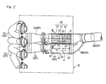
Fig. 2 is a top plan view, on an enlarged scale, showing the exhaust gas purifying apparatus shown inFig. 1 ; -
Fig. 3 is a cross-sectional view taken along the line III-III inFig. 2 , showing one of catalytic units on an enlarged scale; and -
Fig. 4 is a characteristic chart showing the relation between the cell density and the catalyst internal temperature of the catalytic converter in the exhaust gas purifying apparatus, shown inFig. 1 . - A preferred embodiment of the present invention will now be described in detail with particular reference to the accompanying drawings.
Fig. 1 illustrates a schematic side view of a motorcycle having an exhaust gas purifyingapparatus 30 according to a preferred embodiment of the present invention mounted thereon. The illustrated motorcycle is of a structure including a motorcycle frame structure FR having a main frame 1, forming a front frame portion of the motorcycle frame structure FR, and a front fork 2 is pivotally mounted on a front portion of the main frame 1 with a front wheel 4 rotatably supported by a lower end of the front fork 2. A steering handlebar 9 is mounted on an upper bracket 8, which concurrently supports an upper end of the front fork 2. A rear lower portion of the main frame 1 is formed with a swingarm bracket 10, and aswingarm 11 has its front end connected with this swingarm bracket 10 through apivot pin 12 for movement up and down about thepivot pin 12. Arear drive wheel 13 is rotatably supported by a rear end of theswingarm 11 in any manner know to those skilled in the art.Seat rails 14 are connected rigidly with a rear portion of the main frame 1 and forming a rear frame portion of the motorcycle frame structure FR. A combustion engine E is mounted on a lower intermediate portion of the main frame 1 and is drivingly coupled with therear wheel 13 through a drive transmitting member (not shown) such as, for example, a substantially endless chain or belt in any manner known to those skilled in the art. - The
seat rails 14 referred to above includes a motorcycle rider'sseat 19 and a passenger'sseat 20 both mounted thereon, and afuel tank 21 containing an amount of fuel is positioned above the main frame 1, that is, at an upper portion of the motorcycle frame structure and generally intermediate between the handlebar 9 and the rider'sseat 19. A fairing 22 made of a synthetic resin is mounted on a front portion of the motorcycle frame structure for covering a region ranging from forwardly of the handlebar 9 to opposite sides of the front portion of the motorcycle body. - In the illustrated embodiment, the combustion engine E arranged generally intermediate between the front wheel 4 and the
rear wheel 13 is employed in the form of, for example, a four cylinder, four stroke combustion engine and has anengine body 23, which includes acrankcase 24, acylinder block 27, acylinder head 28 mounted atop thecylinder block 27 and acylinder head cover 29 overhanging thecylinder head 28 and atransmission unit 31. - The illustrated motorcycle also includes an exhaust system for discharging exhaust gases G, emitted from the combustion engine E, to the atmosphere. This exhaust system in turn includes four
exhaust tubes 32 fluid connected at an upstream end withrespective exhaust ports 28a, defined in thecylinder head 28, for guiding the exhaust gases G in a direction forwardly and downwardly from the combustion engine E. The exhaust system furthermore includes two intermediateexhaust collecting tubes 34, each fluid connected with respective downstream ends of two of the fourexhaust tubes 32, twocatalytic tubes 37 each fluid connected with a rear end of the associated intermediateexhaust collecting tube 34, and a singleexhaust collector tube 38 fluid connected with respective downstream ends of the twocatalytic tubes 37. Theexhaust collector tube 38 has a downstream end fluid connected with amuffler 33 through a connectingtube 39. - Those various tubes, including the
exhaust tubes 32, theintermediate exhaust tubes 34, thecatalytic tubes 37, theexhaust collector tube 38 and the connectingtube 39, and themuffler 33 altogether form an exhaust passageway EP. The exhaustgas purifying apparatus 30 designed in accordance with the present invention is disposed on this exhaust passageway EP for substantially purifying exhaust gases G by means of a catalytic reaction as will be detailed subsequently. -
Fig. 2 illustrates the exhaustgas purifying apparatus 30 in a top plan representation on an enlarged scale. Acatalytic converter 40 forming a part of the exhaustgas purifying apparatus 30 is accommodated within each of thecatalytic tubes 37 referred to above. Thiscatalytic converter 40 includes a singletubular casing 41 and upstream and downstreamcatalytic units tubular casing 41 in a series connected relation with each other in a direction conforming to the direction X of flow of the exhaust gases G. Those upstream and downstreamcatalytic units catalytic tubes 37 are spaced a distance from each other in a direction conforming to the longitudinal axis C of the associatedtubular casing 41, that is, the direction X of flow of the exhaust gases, with aspace 44 defined between those upstream and downstreamcatalytic units tubular casings 41 is made of a metallic material such as, for example, stainless steel and a portion of the respectivetubular casing 41 generally aligned with thespace 44 defined between the upstream and downstreamcatalytic units catalytic tube 37 by means of welding. - Each of the upstream and downstream
catalytic units Fig. 3 showing on an enlarged scale in a cross sectional representation taken along the line III-III inFig. 2 , the upstreamcatalytic unit 42 includes a honeycomb carrier structure of a substantially round sectional configuration, in which a plurality of annularflat plates 46 and a corresponding number of annular undulated orcorrugated plates 47 are alternately and coaxially positioned with one undulatedplate 47 sandwiched between the neighboringflat plates 46 to define a multiplicity of substantially elongated passages orcells 48 extending in a direction substantially parallel to the longitudinal axis C for the flow of the exhaust gases G therethrough. Theflat plates 46 and the undulatedplates 47 carry the catalyst deposited thereon as will be detailed subsequently. - It is to be noted that the honeycomb carrier structure may not be necessarily limited to the one having the round sectional configuration such as described above, but may have a polygonal sectional configuration such as, for example, a hexagonal sectional configuration.
- The downstream
catalytic unit 43 shown inFig. 2 is similarly comprised of a honeycomb carrier structure substantially similar in shape to that of the upstreamcatalytic unit 42 described above, but having the honeycomb carrier structure of a cell density different from that of the honeycomb carrier structure employed in the upstreamcatalytic unit 42 by the reason which will be described later. The cell density referred to hereinbefore and hereinafter means the density of thecells 48 employed per unitary capacity of the honeycomb carrier structure employed in each of the upstream and downstreamcatalytic units - As hereinabove described, the downstream
catalytic unit 43 includes the honeycomb carrier structure having a cell density higher than that of the honeycomb carrier structure employed in the upper streamcatalytic unit 42. By way of example, the cell density in the upstreamcatalytic unit 42 is chosen to be 300 cells per square inch as has hitherto been employed, but the cell density of the downstreamcatalytic unit 43 is chosen to be 600 cells per square inch. - Also, the capacity of the honeycomb carrier structure (hereinafter referred to as the honeycomb capacity) in the downstream
catalytic unit 43 is smaller than that of the honeycomb carrier structure in the upstreamcatalytic unit 42. In other words, although the upstream and downstreamcatalytic units catalytic unit 43 as measured in a direction conforming to the longitudinal axis C thereof is smaller than the length L1 of the uppercatalytic unit 42 as measured similarly. - For the catalyst carried by the honeycomb carrier structure, rhodium and platinum have hitherto been generally employed and, in particular, rhodium has been largely used as a so-called major catalyst element because it has the highest capability of substantially purifying CO, HC and NOX compounds contained in the exhaust gases. However, rhodium is an expensive element and is marketed in insignificant quantities and, therefore, in the event that the production of the exhaust
gas purifying apparatuses 30 increases, it may be expected that it would become difficult to secure the required amount of the major catalyst element. - In view of the above, in order to save the resource of rhodium, the embodiment now under discussion makes use of the upstream
catalytic unit 42 comprised of the honeycomb carrier structure having deposited thereon a catalyst composition of a kind containing paradigm and rhodium, in which the proportion (the weight based percentage) of paradigm used is greater than that of the rhodium used, and, also, make use of the downstreamcatalytic unit 43 comprised of the honeycomb carrier structure having deposited thereon a catalyst composition of a kind containing platinum and rhodium, in which the proportion of platinum used is greater than that of rhodium used. It is to be noted that the amount of rhodium, which is used as a major catalyst element and is carried by the corresponding honeycomb carrier structure per unit capacity, is so chosen as to be greater in the downstreamcatalytic unit 43 than in the upstreamcatalytic unit 42. - Hereinafter, the operation of the exhaust
gas purifying apparatus 30 will be described. Exhaust gases G emitted from the combustion engine E shown inFig. 1 are guided to flow from the fourexhaust ports 28a, defined in thecylinder head 28, into the associatedexhaust tubes 32. The exhaust gases G so introduced into the fourexhaust tubes 32 are then merged into two streams, which flow through the intermediateexhaust collecting tubes 34 and then through thecatalytic tubes 37, respectively, and are thereafter discharged to the atmosphere through theexhaust collector tube 38 and then through the connectingtube 39 by way of themuffler 33. - As best shown in
Fig. 2 , the exhaust gases G introduced from the fourexhaust tubes 32 into thecatalytic tubes 37 by way of theintermediate collecting tubes 34 flow through the upstream and downstreamcatalytic units catalytic converters 40 that are accommodated respectively within thecatalytic tubes 37. The exhaust gases G flowing through the upstream and downstreamcatalytic units catalytic converters 40 in the manner described above are substantially purified by the catalytic reaction taking place in each of the upstream and downstreamcatalytic units - When the exhaust gases G flows through the
cells 48 shown inFig. 3 , it may occur that the degree of reaction taking place at portions of thecells 48, which contact surfaces of theflat plates 48 or the undulatedplates 47, and the degree of reaction taking place at center portions of thecells 48, which do not contact surfaces of theflat plates 48 or the undulatedplates 47 are different from each other. As a result, the extent to which the exhaust gases G are substantially purified after they have passed through the upstreamcatalytic unit 42 shown inFig. 2 may vary within the transverse section, but those exhaust gases are, after having once been mixed within thespace 44 delimited between the upstream and downstreamcatalytic units catalytic unit 43. Accordingly, the exhaust gases are substantially purified with no local variation occurring from place to place and the purifying capability can thus be increased. -
Fig. 4 is a characteristic chart showing the relation between the cell density and the catalyst internal temperature of each of thecatalytic converters 40, which chart was obtained as a result of a series of endurance tests carried out with the motorcycle under a predetermined pattern. Legends "TMAX" and "TMIN" shown inFig. 4 represent the maximum value of the catalyst internal temperature and the minimum value of the catalyst internal temperature, respectively; and ΔT represents the temperature difference between the maximum catalyst internal temperature TMAX and the minimum catalyst internal temperature TMIN. The minimum catalyst internal temperature TMIN represents the temperature measured at the time the motorcycle under the series of endurance tests was driven in a stabilized mode, and is substantially constant regardless of the cell density. On the other hand, the maximum catalyst internal temperature TMAX tends to abruptly increase proportionally when the cell density is of a value equal to or higher than 400 cells per square inch, accompanied by a corresponding increase of the temperature difference ΔT. - The reason for the increase of the maximum catalyst internal temperature TMAX with increase of the cell density as discussed above is as follows. At the time of an abrupt deceleration mode during the endurance tests, in the combustion engine E shown in
Fig. 1 , a throttle valve is closed with a reduced amount of air introduced into the combustion engine, but fuel sticking to wall surfaces of the intake port flows into the combustion chamber. Therefore, the air-fuel mixture introduced into the combustion chamber will be enriched in admixture of the fuel so flowing into the combustion chamber to such an extent as to result in an incomplete combustion. Once the incomplete combustion occurs, the exhaust gases containing substantial amounts of CO and HC will be discharged from theexhaust ports 28a. - On the other hand, with the
catalytic converter 40 of the structure shown in and described with particular reference toFig. 2 , if the cell density increases, the heat value per unitary surface area increases with increase of the number of the cells. In other words, since the capability of substantially purifying the exhaust gases G increases, the catalytic reaction with CO and HC, which tend to be generated in a large amount at the time of the abrupt deceleration mode described above, can be promoted, resulting in increase of the maximum catalyst internal temperature TMAX. - Also, the honeycomb carrier structure having a high cell density does not only require the use of a foil-like metal plate having a small thickness for each of the flat and undulated plates employed in each of the catalytic units, but also incurs increase of the temperature difference ΔT between the maximum catalyst internal temperature TMAX and the minimum catalyst internal temperature TMIN with the maximum catalyst internal temperature TMAX increased. Accordingly, the honeycomb carrier structure having such a high cell density is susceptible to reduction in durability when it undergoes thermal contraction repeatedly by the effect of the large temperature difference ΔT.
- For the reason discussed above, the upstream
catalytic unit 42 of each of thecatalytic converters 40 is susceptible to reduction in durability with increase of the cell density since the exhaust gases G of a high temperature are introduced thereinto from the combustion engine E. In view of this, the upstreamcatalytic unit 42 of each of thecatalytic converters 40 makes use of the honeycomb carrier structure having a cell density of about 300 cells per square inch and, hence, having a small temperature difference ΔT between the maximum and minimum catalyst internal temperatures as shown inFig. 4 . - On the other hand, although the downstream
catalytic unit 43 of each of thecatalytic converters 40 shown inFig. 2 makes use of the honeycomb carrier structure having a cell density of 600 cells per square inch, since the exhaust gases G once substantially purified by the upstreamcatalytic unit 42 flow into such downstreamcatalytic unit 43, it will scarcely affected by influences brought about by the previously discussed incomplete combustion and, therefore, the maximum catalyst internal temperature TMAX thereof can be lowered to a point shown by P inFig. 4 . Accordingly, the temperature difference ΔT is of a value about comparable with that exhibited when the catalytic unit has a cell density equal to or lower than 200 cells per square inch and, thus, an advantage can be appreciated in terms of the durability. - As hereinabove discussed, a sufficient durability can be secured in each of the
catalytic converters 40 shown inFig. 2 . - Reviewing the characteristic chart of
Fig. 4 , the upstreamcatalytic unit 42 of each of thecatalytic converters 40 is preferred to have a cell density lower than 400 cells per square inch so that the temperature difference ΔT will not increase unduly and, on the other hand, the downstreamcatalytic unit 43 of each of thecatalytic converters 40 is preferred to have a cell density of a value equal to or higher than 400 cells per square inch and, more preferably, of a value equal to or higher than 500 cells per square inch where the purifying performance is desired to be increased. Considering that although with the cell density increased, the honeycomb surface area as defined previously correspondingly increases enough to increase the capability of substantially purifying the exhaust gases, it also results in increase of the flow resistance of the exhaust gases, accompanied by reduction in engine performance. Therefore, the cell density is preferably not higher than 800 cells per square inch to avoid the excessive flow resistance occurring. - The exhaust gas purifying capability of each of the
catalytic converters 40 will now be descried. In the upstreamcatalytic unit 42 employed in each of thecatalytic converters 40, paradigm reacts with the HC component contained in the exhaust gases G and, on the other hand, when the exhaust gases G containing a high concentration of fuel flow thereinto, rhodium reacts with the CO component generated from the paradigm. Accordingly, the exhaust gases G can be substantially purified by the synergic effects of rhodium and paradigm. Also, as described above, in each of thecatalytic converters 40, the exhaust gases G can be substantially purified, with no local variation, due to the presence of thespace 44 delimited between the upstream and downstreamcatalytic units - In addition, although the exhaust gas purifying capability depends on the honeycomb surface area in which the catalyst is carried, not on the total amount of the catalyst used, since the honeycomb surface area increase as a result of the downstream
catalytic unit 43 having a high cell density of 600 cells per square inch, the purifying capability can be increased by a degree corresponding to the quantity of the honeycomb surface area increased. Moreover, since the amount of rhodium, which is the major catalyst element most effective to remove the CO and HC compounds contained in the exhaust gases G, carried by the corresponding honeycomb carrier structure in the downstreamcatalytic unit 43 is greater than that in the upstreamcatalytic unit 42, a sufficient purifying capability is secured. Accordingly, increase of the purifying capability of each of thecatalytic converters 40 can be appreciated. - On the other hand, since the downstream
catalytic unit 43 makes use of the honeycomb carrier structure having a high cell density with the honeycomb surface area increased and does therefore has the purifying capability increased by a degree corresponding to the amount of the honeycomb surface area increased, the honeycomb capacity can be reduced where the same purifying capability is desired, and, therefore, the length L2 thereof as measured in the direction conforming to the longitudinal axis C is chosen to be smaller than the length L1 of the upstreamcatalytic unit 42. Accordingly, the size of the respectivecatalytic converter 40 can be reduced in a quantity corresponding to the quantity of the capacity of the downstreamcatalytic unit 43 so reduced. Also, since the respectivecatalytic converter 40 includes the two, i.e., upstream and downstreamcatalytic units tubular casing 41, thecatalytic converter 40 represents a single assembly and can be easily handled. - Since each of the
catalytic converters 40 is of such a structure that the honeycomb capacity will not decrease because of the cell density of the honeycomb carrier structure in the upstreamcatalytic unit 42 being low as is the case with the conventional case, a substantial amount of inexpensive paradigm is carried thereby as a catalyst. On the other hand, while the honeycomb carrier structure of the downstreamcatalytic unit 43 carries a larger amount of expensive rhodium per unit capacity than that in the honeycomb carrier structure of the upstreamcatalytic unit 42, the honeycomb capacity of the downstreamcatalytic unit 43 is small as a result of the cell density being high. Since the total amount of the catalyst is proportionate to the honeycomb capacity, even in the case that the amount of the catalyst carried per capacity is large, the total amount of the catalyst including the major catalyst element can be reduced in a quantity corresponding to the amount of the honeycomb capacity reduced and, as a result thereof, the total amount of the expensive rhodium used can be suppressed. Accordingly, thecatalytic converter 40 is effective to reduce the cost of the material due to the catalyst reduced. Also, although rhodium is a catalyst metal that is a rare metal because of an insignificant quantity thereof being placed in the market, reduction in total amount achieved in the manner described hereinbefore brings about such an advantage that even when the production of thecatalytic converters 40 increases, the required amount of rhodium can be easily secured. - It is to be noted that although each of the
catalytic converters 40 has been shown and described as made up of thetubular casing 41, having a substantially identical diameter over the entire length thereof, and the twocatalytic units tubular casing 41 and spaced a distance from each other, the respective catalytic converter may be so designed and so configured that using a tubular body having two longitudinal locations thereof coaxial with each other, but having diameters different from each other, catalytic units of respective diameters different from each other may be accommodated within such tubular body. Also, the catalytic converter may have catalytic units more than two. In such case, in at least two of three or more catalytic units are such that the catalytic unit positioned downstream should have the cell density higher than that of the catalytic unit positioned upstream, should have the honeycomb capacity smaller than that of the upstream catalytic unit and should include the larger amount of the element, due to become the major catalyst, carried per unit capacity than that in the upstream catalytic unit. - Although the present invention has been fully described in connection with the preferred embodiments thereof with reference to the accompanying drawings which are used only for the purpose of illustration, those skilled in the art will readily conceive numerous changes and modifications within the framework of obviousness upon the reading of the specification herein presented of the present invention. Accordingly, such changes and modifications are, unless they depart from the scope of the present invention as delivered from the claims annexed hereto, to be construed as included therein.
Claims (9)
- An exhaust gas purifying apparatus disposed on an exhaust passage, through which exhaust gases emitted from a combustion engine flows, for purifying those exhaust gases by means of a catalytic reaction, which apparatus comprises:a plurality of catalytic units disposed in series with each other in a direction conforming to the direction of flow of the exhaust gases;each of those catalytic units including a honeycomb carrier structure and a catalyst carried by the honeycomb carrier structure; andin at least two of the plural catalytic units, the downstream catalytic unit positioned downstream with respect to the direction of flow of the exhaust gases has a higher cell density, a smaller capacity of the honeycomb carrier structure and a larger amount of an element, due to become a major catalyst, carried thereby per unitary capacity than those in the upstream catalytic unit positioned upstream of the downstream catalytic unit.
- The exhaust gas purifying apparatus as claimed in claim 1, in which the element due to become the major catalyst element is rhodium.
- The exhaust gas purifying apparatus as claimed in claim 2, in which the honeycomb carrier structure of the downstream catalytic unit carries a catalyst composition of a kind containing rhodium and platinum, in which the proportion of platinum used is greater than that of rhodium used in weight based percentage.
- The exhaust gas purifying apparatus as claimed in claim 1, in which paradigm is contained in the catalyst used on the upstream catalytic unit.
- The exhaust gas purifying apparatus as claimed in claim 4, in which the honeycomb carrier structure of the upstream catalytic unit carries a catalyst composition of a kind containing rhodium and paradigm, in which the proportion of paradigm used is greater than that of rhodium used in weight based percentage.
- The exhaust gas purifying apparatus as claimed in claim 1, in which the upstream and downstream catalytic units are retained within a single tubular casing having a longitudinal axis conforming to the direction of flow of the exhaust gases and are axially spaced a distance from each other.
- The exhaust gas purifying apparatus as claimed in claim 1, the honeycomb carrier structure of the downstream catalytic unit is made of a metallic material and has a cell density equal to or higher than 400 cells per square inch.
- The exhaust gas purifying apparatus as claimed in claim 7, in which the cell density of the honeycomb carrier structure of the downstream catalytic unit is equal to or higher than 500 per square inch.
- The exhaust gas purifying apparatus as claimed in claim 7, in which the cell density of the honeycomb carrier structure of the downstream catalytic unit is equal to or lower than 800 cells per square inch.
Applications Claiming Priority (2)
| Application Number | Priority Date | Filing Date | Title |
|---|---|---|---|
| JP2007297106A JP5183162B2 (en) | 2007-11-15 | 2007-11-15 | Exhaust purification device |
| PCT/JP2008/003227 WO2009063602A1 (en) | 2007-11-15 | 2008-11-07 | Exhaust gas purifying apparatus |
Publications (3)
| Publication Number | Publication Date |
|---|---|
| EP2221461A1 true EP2221461A1 (en) | 2010-08-25 |
| EP2221461A4 EP2221461A4 (en) | 2012-07-25 |
| EP2221461B1 EP2221461B1 (en) | 2017-05-03 |
Family
ID=40638457
Family Applications (1)
| Application Number | Title | Priority Date | Filing Date |
|---|---|---|---|
| EP08849217.8A Not-in-force EP2221461B1 (en) | 2007-11-15 | 2008-11-07 | Exhaust gas purifying apparatus |
Country Status (4)
| Country | Link |
|---|---|
| US (1) | US8398926B2 (en) |
| EP (1) | EP2221461B1 (en) |
| JP (1) | JP5183162B2 (en) |
| WO (1) | WO2009063602A1 (en) |
Cited By (1)
| Publication number | Priority date | Publication date | Assignee | Title |
|---|---|---|---|---|
| EP2871341A1 (en) * | 2013-11-07 | 2015-05-13 | Toyota Jidosha Kabushiki Kaisha | Catalytic converter |
Families Citing this family (3)
| Publication number | Priority date | Publication date | Assignee | Title |
|---|---|---|---|---|
| JP5599141B2 (en) * | 2008-09-04 | 2014-10-01 | 株式会社キャタラー | Exhaust gas purification catalyst for motorcycles |
| EP2818640A3 (en) * | 2013-06-26 | 2015-08-19 | Honeywell International Inc. | Turbocharger with annular rotary bypass valve for the turbine, and catalyst disposed in the bypass channel of the turbine housing |
| US10526043B2 (en) * | 2016-06-24 | 2020-01-07 | V&H Performance, Llc | Motorcycle exhaust with catalytic converter |
Family Cites Families (11)
| Publication number | Priority date | Publication date | Assignee | Title |
|---|---|---|---|---|
| JPS5879088A (en) * | 1981-11-05 | 1983-05-12 | Matsushita Electric Ind Co Ltd | Reforming apparatus of hydrocarbon fuel |
| JPS6017220A (en) | 1983-07-09 | 1985-01-29 | Honda Motor Co Ltd | Exhaust purification device for engine in motorcycle |
| US5403559A (en) * | 1989-07-18 | 1995-04-04 | Emitec Gesellschaft Fuer Emissionstechnologie | Device for cleaning exhaust gases of motor vehicles |
| JPH0394836A (en) * | 1989-09-05 | 1991-04-19 | Cataler Kogyo Kk | Carrier for exhaust gas purifier |
| JP3272464B2 (en) * | 1992-04-23 | 2002-04-08 | マツダ株式会社 | Exhaust gas purification catalyst structure |
| DE4434673A1 (en) * | 1994-09-28 | 1996-04-04 | Emitec Emissionstechnologie | Electrically heated catalyst |
| US5768889A (en) | 1995-09-22 | 1998-06-23 | Emitec Gesellschaft Fuer Emissions-Technologie Mbh | Device for catalytically converting exhaust gases in an exhaust system |
| US6375910B1 (en) * | 1999-04-02 | 2002-04-23 | Engelhard Corporation | Multi-zoned catalytic trap and methods of making and using the same |
| JP4503304B2 (en) * | 2004-01-29 | 2010-07-14 | 株式会社キャタラー | Exhaust gas purification catalyst |
| JP4833605B2 (en) | 2005-07-21 | 2011-12-07 | 株式会社キャタラー | Exhaust gas purification catalyst |
| US7718150B2 (en) * | 2007-04-17 | 2010-05-18 | Ford Global Technologies, Llc | Reverse platinum group metal zoned lean NOx trap system and method of use |
-
2007
- 2007-11-15 JP JP2007297106A patent/JP5183162B2/en not_active Expired - Fee Related
-
2008
- 2008-11-07 WO PCT/JP2008/003227 patent/WO2009063602A1/en not_active Ceased
- 2008-11-07 EP EP08849217.8A patent/EP2221461B1/en not_active Not-in-force
- 2008-11-07 US US12/739,384 patent/US8398926B2/en not_active Expired - Fee Related
Non-Patent Citations (2)
| Title |
|---|
| No further relevant documents disclosed * |
| See also references of WO2009063602A1 * |
Cited By (1)
| Publication number | Priority date | Publication date | Assignee | Title |
|---|---|---|---|---|
| EP2871341A1 (en) * | 2013-11-07 | 2015-05-13 | Toyota Jidosha Kabushiki Kaisha | Catalytic converter |
Also Published As
| Publication number | Publication date |
|---|---|
| JP5183162B2 (en) | 2013-04-17 |
| WO2009063602A1 (en) | 2009-05-22 |
| US8398926B2 (en) | 2013-03-19 |
| JP2009121371A (en) | 2009-06-04 |
| EP2221461B1 (en) | 2017-05-03 |
| EP2221461A4 (en) | 2012-07-25 |
| US20100257851A1 (en) | 2010-10-14 |
Similar Documents
| Publication | Publication Date | Title |
|---|---|---|
| CA1055845A (en) | Catalytic type exhaust gas purifying device | |
| US8087230B2 (en) | Exhaust system for motor vehicles | |
| US7290388B2 (en) | Motorcycle exhaust system | |
| US7585478B2 (en) | Exhaust-gas purifying catalyst | |
| JPH09133032A (en) | Exhaust gas purification device for internal combustion engine | |
| EP3505732B1 (en) | Engine exhaust device | |
| EP2221461B1 (en) | Exhaust gas purifying apparatus | |
| US10626781B2 (en) | Exhaust device of engine | |
| CA2249262A1 (en) | Caltalytic converter for a tailpipe including apparatus for relieving back pressure | |
| US7484361B2 (en) | Exhaust gas purifying apparatus of motorcycle | |
| US5849250A (en) | Auxiliary catalytic converter having a back pressure relief device | |
| US20160102591A1 (en) | Catalytic converter | |
| JP2006329030A (en) | Exhaust device and engine device and vehicle including the same | |
| WO2009137110A1 (en) | Treatment of internal combustion engine exhaust using immobilized ceramic fiber materials | |
| CA1101638A (en) | Process | |
| EP1094207A1 (en) | Silencer for two-stroke engines containing a catalytic device and catalytic device therefor | |
| KR101000224B1 (en) | Car Catalyst | |
| JP2018155218A (en) | Saddle-riding type vehicle | |
| JPH08193512A (en) | Exhaust gas purification device | |
| US7858052B2 (en) | Catalytic converter optimization | |
| JP2018159368A (en) | Exhaust emission control device | |
| US20050020447A1 (en) | Catalyst comprising coated substrate | |
| Coultas et al. | New, Highly Durable, Low PGM Motorcycle Catalyst Formulations for the Indian 2-Wheeler Market | |
| JP2004181374A (en) | Exhaust gas purification catalyst | |
| US10605139B2 (en) | Catalytic converter for classic cars |
Legal Events
| Date | Code | Title | Description |
|---|---|---|---|
| PUAI | Public reference made under article 153(3) epc to a published international application that has entered the european phase |
Free format text: ORIGINAL CODE: 0009012 |
|
| 17P | Request for examination filed |
Effective date: 20100609 |
|
| AK | Designated contracting states |
Kind code of ref document: A1 Designated state(s): AT BE BG CH CY CZ DE DK EE ES FI FR GB GR HR HU IE IS IT LI LT LU LV MC MT NL NO PL PT RO SE SI SK TR |
|
| AX | Request for extension of the european patent |
Extension state: AL BA MK RS |
|
| DAX | Request for extension of the european patent (deleted) | ||
| A4 | Supplementary search report drawn up and despatched |
Effective date: 20120622 |
|
| RIC1 | Information provided on ipc code assigned before grant |
Ipc: F01N 3/10 20060101ALI20120618BHEP Ipc: F01N 3/28 20060101AFI20120618BHEP Ipc: B01J 23/46 20060101ALI20120618BHEP Ipc: B01D 53/94 20060101ALI20120618BHEP |
|
| 17Q | First examination report despatched |
Effective date: 20160310 |
|
| GRAP | Despatch of communication of intention to grant a patent |
Free format text: ORIGINAL CODE: EPIDOSNIGR1 |
|
| INTG | Intention to grant announced |
Effective date: 20161220 |
|
| GRAS | Grant fee paid |
Free format text: ORIGINAL CODE: EPIDOSNIGR3 |
|
| GRAA | (expected) grant |
Free format text: ORIGINAL CODE: 0009210 |
|
| AK | Designated contracting states |
Kind code of ref document: B1 Designated state(s): AT BE BG CH CY CZ DE DK EE ES FI FR GB GR HR HU IE IS IT LI LT LU LV MC MT NL NO PL PT RO SE SI SK TR |
|
| REG | Reference to a national code |
Ref country code: GB Ref legal event code: FG4D |
|
| REG | Reference to a national code |
Ref country code: AT Ref legal event code: REF Ref document number: 890257 Country of ref document: AT Kind code of ref document: T Effective date: 20170515 Ref country code: CH Ref legal event code: EP |
|
| REG | Reference to a national code |
Ref country code: IE Ref legal event code: FG4D |
|
| REG | Reference to a national code |
Ref country code: DE Ref legal event code: R096 Ref document number: 602008050124 Country of ref document: DE |
|
| REG | Reference to a national code |
Ref country code: NL Ref legal event code: MP Effective date: 20170503 |
|
| REG | Reference to a national code |
Ref country code: AT Ref legal event code: MK05 Ref document number: 890257 Country of ref document: AT Kind code of ref document: T Effective date: 20170503 |
|
| REG | Reference to a national code |
Ref country code: LT Ref legal event code: MG4D |
|
| PG25 | Lapsed in a contracting state [announced via postgrant information from national office to epo] |
Ref country code: FI Free format text: LAPSE BECAUSE OF FAILURE TO SUBMIT A TRANSLATION OF THE DESCRIPTION OR TO PAY THE FEE WITHIN THE PRESCRIBED TIME-LIMIT Effective date: 20170503 Ref country code: GR Free format text: LAPSE BECAUSE OF FAILURE TO SUBMIT A TRANSLATION OF THE DESCRIPTION OR TO PAY THE FEE WITHIN THE PRESCRIBED TIME-LIMIT Effective date: 20170804 Ref country code: AT Free format text: LAPSE BECAUSE OF FAILURE TO SUBMIT A TRANSLATION OF THE DESCRIPTION OR TO PAY THE FEE WITHIN THE PRESCRIBED TIME-LIMIT Effective date: 20170503 Ref country code: LT Free format text: LAPSE BECAUSE OF FAILURE TO SUBMIT A TRANSLATION OF THE DESCRIPTION OR TO PAY THE FEE WITHIN THE PRESCRIBED TIME-LIMIT Effective date: 20170503 Ref country code: NO Free format text: LAPSE BECAUSE OF FAILURE TO SUBMIT A TRANSLATION OF THE DESCRIPTION OR TO PAY THE FEE WITHIN THE PRESCRIBED TIME-LIMIT Effective date: 20170803 Ref country code: HR Free format text: LAPSE BECAUSE OF FAILURE TO SUBMIT A TRANSLATION OF THE DESCRIPTION OR TO PAY THE FEE WITHIN THE PRESCRIBED TIME-LIMIT Effective date: 20170503 Ref country code: ES Free format text: LAPSE BECAUSE OF FAILURE TO SUBMIT A TRANSLATION OF THE DESCRIPTION OR TO PAY THE FEE WITHIN THE PRESCRIBED TIME-LIMIT Effective date: 20170503 |
|
| REG | Reference to a national code |
Ref country code: FR Ref legal event code: PLFP Year of fee payment: 10 |
|
| PG25 | Lapsed in a contracting state [announced via postgrant information from national office to epo] |
Ref country code: IS Free format text: LAPSE BECAUSE OF FAILURE TO SUBMIT A TRANSLATION OF THE DESCRIPTION OR TO PAY THE FEE WITHIN THE PRESCRIBED TIME-LIMIT Effective date: 20170903 Ref country code: PL Free format text: LAPSE BECAUSE OF FAILURE TO SUBMIT A TRANSLATION OF THE DESCRIPTION OR TO PAY THE FEE WITHIN THE PRESCRIBED TIME-LIMIT Effective date: 20170503 Ref country code: SE Free format text: LAPSE BECAUSE OF FAILURE TO SUBMIT A TRANSLATION OF THE DESCRIPTION OR TO PAY THE FEE WITHIN THE PRESCRIBED TIME-LIMIT Effective date: 20170503 Ref country code: LV Free format text: LAPSE BECAUSE OF FAILURE TO SUBMIT A TRANSLATION OF THE DESCRIPTION OR TO PAY THE FEE WITHIN THE PRESCRIBED TIME-LIMIT Effective date: 20170503 Ref country code: NL Free format text: LAPSE BECAUSE OF FAILURE TO SUBMIT A TRANSLATION OF THE DESCRIPTION OR TO PAY THE FEE WITHIN THE PRESCRIBED TIME-LIMIT Effective date: 20170503 Ref country code: BG Free format text: LAPSE BECAUSE OF FAILURE TO SUBMIT A TRANSLATION OF THE DESCRIPTION OR TO PAY THE FEE WITHIN THE PRESCRIBED TIME-LIMIT Effective date: 20170803 |
|
| PG25 | Lapsed in a contracting state [announced via postgrant information from national office to epo] |
Ref country code: EE Free format text: LAPSE BECAUSE OF FAILURE TO SUBMIT A TRANSLATION OF THE DESCRIPTION OR TO PAY THE FEE WITHIN THE PRESCRIBED TIME-LIMIT Effective date: 20170503 Ref country code: CZ Free format text: LAPSE BECAUSE OF FAILURE TO SUBMIT A TRANSLATION OF THE DESCRIPTION OR TO PAY THE FEE WITHIN THE PRESCRIBED TIME-LIMIT Effective date: 20170503 Ref country code: DK Free format text: LAPSE BECAUSE OF FAILURE TO SUBMIT A TRANSLATION OF THE DESCRIPTION OR TO PAY THE FEE WITHIN THE PRESCRIBED TIME-LIMIT Effective date: 20170503 Ref country code: RO Free format text: LAPSE BECAUSE OF FAILURE TO SUBMIT A TRANSLATION OF THE DESCRIPTION OR TO PAY THE FEE WITHIN THE PRESCRIBED TIME-LIMIT Effective date: 20170503 Ref country code: SK Free format text: LAPSE BECAUSE OF FAILURE TO SUBMIT A TRANSLATION OF THE DESCRIPTION OR TO PAY THE FEE WITHIN THE PRESCRIBED TIME-LIMIT Effective date: 20170503 |
|
| REG | Reference to a national code |
Ref country code: DE Ref legal event code: R097 Ref document number: 602008050124 Country of ref document: DE |
|
| PLBE | No opposition filed within time limit |
Free format text: ORIGINAL CODE: 0009261 |
|
| STAA | Information on the status of an ep patent application or granted ep patent |
Free format text: STATUS: NO OPPOSITION FILED WITHIN TIME LIMIT |
|
| 26N | No opposition filed |
Effective date: 20180206 |
|
| PG25 | Lapsed in a contracting state [announced via postgrant information from national office to epo] |
Ref country code: SI Free format text: LAPSE BECAUSE OF FAILURE TO SUBMIT A TRANSLATION OF THE DESCRIPTION OR TO PAY THE FEE WITHIN THE PRESCRIBED TIME-LIMIT Effective date: 20170503 |
|
| PG25 | Lapsed in a contracting state [announced via postgrant information from national office to epo] |
Ref country code: MC Free format text: LAPSE BECAUSE OF FAILURE TO SUBMIT A TRANSLATION OF THE DESCRIPTION OR TO PAY THE FEE WITHIN THE PRESCRIBED TIME-LIMIT Effective date: 20170503 |
|
| GBPC | Gb: european patent ceased through non-payment of renewal fee |
Effective date: 20171107 |
|
| PG25 | Lapsed in a contracting state [announced via postgrant information from national office to epo] |
Ref country code: CH Free format text: LAPSE BECAUSE OF NON-PAYMENT OF DUE FEES Effective date: 20171130 Ref country code: LI Free format text: LAPSE BECAUSE OF NON-PAYMENT OF DUE FEES Effective date: 20171130 |
|
| PG25 | Lapsed in a contracting state [announced via postgrant information from national office to epo] |
Ref country code: LU Free format text: LAPSE BECAUSE OF NON-PAYMENT OF DUE FEES Effective date: 20171107 |
|
| REG | Reference to a national code |
Ref country code: BE Ref legal event code: MM Effective date: 20171130 |
|
| REG | Reference to a national code |
Ref country code: IE Ref legal event code: MM4A |
|
| PG25 | Lapsed in a contracting state [announced via postgrant information from national office to epo] |
Ref country code: MT Free format text: LAPSE BECAUSE OF NON-PAYMENT OF DUE FEES Effective date: 20171107 |
|
| REG | Reference to a national code |
Ref country code: FR Ref legal event code: PLFP Year of fee payment: 11 |
|
| PG25 | Lapsed in a contracting state [announced via postgrant information from national office to epo] |
Ref country code: IE Free format text: LAPSE BECAUSE OF NON-PAYMENT OF DUE FEES Effective date: 20171107 |
|
| PG25 | Lapsed in a contracting state [announced via postgrant information from national office to epo] |
Ref country code: GB Free format text: LAPSE BECAUSE OF NON-PAYMENT OF DUE FEES Effective date: 20171107 Ref country code: BE Free format text: LAPSE BECAUSE OF NON-PAYMENT OF DUE FEES Effective date: 20171130 |
|
| PG25 | Lapsed in a contracting state [announced via postgrant information from national office to epo] |
Ref country code: HU Free format text: LAPSE BECAUSE OF FAILURE TO SUBMIT A TRANSLATION OF THE DESCRIPTION OR TO PAY THE FEE WITHIN THE PRESCRIBED TIME-LIMIT; INVALID AB INITIO Effective date: 20081107 |
|
| PG25 | Lapsed in a contracting state [announced via postgrant information from national office to epo] |
Ref country code: CY Free format text: LAPSE BECAUSE OF NON-PAYMENT OF DUE FEES Effective date: 20170503 |
|
| PG25 | Lapsed in a contracting state [announced via postgrant information from national office to epo] |
Ref country code: TR Free format text: LAPSE BECAUSE OF FAILURE TO SUBMIT A TRANSLATION OF THE DESCRIPTION OR TO PAY THE FEE WITHIN THE PRESCRIBED TIME-LIMIT Effective date: 20170503 |
|
| PG25 | Lapsed in a contracting state [announced via postgrant information from national office to epo] |
Ref country code: PT Free format text: LAPSE BECAUSE OF FAILURE TO SUBMIT A TRANSLATION OF THE DESCRIPTION OR TO PAY THE FEE WITHIN THE PRESCRIBED TIME-LIMIT Effective date: 20170503 |
|
| PGFP | Annual fee paid to national office [announced via postgrant information from national office to epo] |
Ref country code: IT Payment date: 20201013 Year of fee payment: 13 Ref country code: FR Payment date: 20201013 Year of fee payment: 13 |
|
| REG | Reference to a national code |
Ref country code: DE Ref legal event code: R081 Ref document number: 602008050124 Country of ref document: DE Owner name: KAWASAKI MOTORS, LTD., AKASHI-SHI, JP Free format text: FORMER OWNER: KAWASAKI JUKOGYO KABUSHIKI KAISHA, KOBE-SHI, HYOGO, JP |
|
| PG25 | Lapsed in a contracting state [announced via postgrant information from national office to epo] |
Ref country code: FR Free format text: LAPSE BECAUSE OF NON-PAYMENT OF DUE FEES Effective date: 20211130 |
|
| PG25 | Lapsed in a contracting state [announced via postgrant information from national office to epo] |
Ref country code: IT Free format text: LAPSE BECAUSE OF NON-PAYMENT OF DUE FEES Effective date: 20211107 |
|
| PGFP | Annual fee paid to national office [announced via postgrant information from national office to epo] |
Ref country code: DE Payment date: 20220621 Year of fee payment: 15 |
|
| REG | Reference to a national code |
Ref country code: DE Ref legal event code: R119 Ref document number: 602008050124 Country of ref document: DE |
|
| PG25 | Lapsed in a contracting state [announced via postgrant information from national office to epo] |
Ref country code: DE Free format text: LAPSE BECAUSE OF NON-PAYMENT OF DUE FEES Effective date: 20240601 |
|
| PG25 | Lapsed in a contracting state [announced via postgrant information from national office to epo] |
Ref country code: DE Free format text: LAPSE BECAUSE OF NON-PAYMENT OF DUE FEES Effective date: 20240601 |