EP2221433A2 - Floor insulation structure - Google Patents
Floor insulation structure Download PDFInfo
- Publication number
- EP2221433A2 EP2221433A2 EP10153971A EP10153971A EP2221433A2 EP 2221433 A2 EP2221433 A2 EP 2221433A2 EP 10153971 A EP10153971 A EP 10153971A EP 10153971 A EP10153971 A EP 10153971A EP 2221433 A2 EP2221433 A2 EP 2221433A2
- Authority
- EP
- European Patent Office
- Prior art keywords
- layer
- insulation structure
- perforated
- insulation
- apertures
- Prior art date
- Legal status (The legal status is an assumption and is not a legal conclusion. Google has not performed a legal analysis and makes no representation as to the accuracy of the status listed.)
- Withdrawn
Links
- 238000009413 insulation Methods 0.000 title claims abstract description 57
- 239000000463 material Substances 0.000 claims abstract description 39
- 239000006260 foam Substances 0.000 claims abstract description 16
- 239000004033 plastic Substances 0.000 claims abstract description 13
- 229920003023 plastic Polymers 0.000 claims abstract description 13
- 238000010438 heat treatment Methods 0.000 claims description 19
- 238000009434 installation Methods 0.000 claims description 13
- 238000000034 method Methods 0.000 claims description 9
- 239000004698 Polyethylene Substances 0.000 claims description 3
- -1 polyethylene Polymers 0.000 claims description 3
- 229920000573 polyethylene Polymers 0.000 claims description 3
- 238000004519 manufacturing process Methods 0.000 claims 1
- 239000004794 expanded polystyrene Substances 0.000 description 6
- 230000007261 regionalization Effects 0.000 description 5
- 239000012774 insulation material Substances 0.000 description 3
- 239000011490 mineral wool Substances 0.000 description 2
- 229910000831 Steel Inorganic materials 0.000 description 1
- 230000015572 biosynthetic process Effects 0.000 description 1
- 239000000945 filler Substances 0.000 description 1
- 239000012530 fluid Substances 0.000 description 1
- 238000005755 formation reaction Methods 0.000 description 1
- 238000002955 isolation Methods 0.000 description 1
- 238000010030 laminating Methods 0.000 description 1
- 238000003475 lamination Methods 0.000 description 1
- 239000000203 mixture Substances 0.000 description 1
- 238000003825 pressing Methods 0.000 description 1
- 239000010959 steel Substances 0.000 description 1
- 238000004804 winding Methods 0.000 description 1
Images

Classifications
-
- E—FIXED CONSTRUCTIONS
- E04—BUILDING
- E04F—FINISHING WORK ON BUILDINGS, e.g. STAIRS, FLOORS
- E04F15/00—Flooring
- E04F15/18—Separately-laid insulating layers; Other additional insulating measures; Floating floors
-
- B—PERFORMING OPERATIONS; TRANSPORTING
- B32—LAYERED PRODUCTS
- B32B—LAYERED PRODUCTS, i.e. PRODUCTS BUILT-UP OF STRATA OF FLAT OR NON-FLAT, e.g. CELLULAR OR HONEYCOMB, FORM
- B32B3/00—Layered products comprising a layer with external or internal discontinuities or unevennesses, or a layer of non-planar shape; Layered products comprising a layer having particular features of form
- B32B3/10—Layered products comprising a layer with external or internal discontinuities or unevennesses, or a layer of non-planar shape; Layered products comprising a layer having particular features of form characterised by a discontinuous layer, i.e. formed of separate pieces of material
- B32B3/12—Layered products comprising a layer with external or internal discontinuities or unevennesses, or a layer of non-planar shape; Layered products comprising a layer having particular features of form characterised by a discontinuous layer, i.e. formed of separate pieces of material characterised by a layer of regularly- arranged cells, e.g. a honeycomb structure
-
- E—FIXED CONSTRUCTIONS
- E04—BUILDING
- E04B—GENERAL BUILDING CONSTRUCTIONS; WALLS, e.g. PARTITIONS; ROOFS; FLOORS; CEILINGS; INSULATION OR OTHER PROTECTION OF BUILDINGS
- E04B1/00—Constructions in general; Structures which are not restricted either to walls, e.g. partitions, or floors or ceilings or roofs
- E04B1/62—Insulation or other protection; Elements or use of specified material therefor
- E04B1/74—Heat, sound or noise insulation, absorption, or reflection; Other building methods affording favourable thermal or acoustical conditions, e.g. accumulating of heat within walls
- E04B1/88—Insulating elements for both heat and sound
-
- F—MECHANICAL ENGINEERING; LIGHTING; HEATING; WEAPONS; BLASTING
- F24—HEATING; RANGES; VENTILATING
- F24D—DOMESTIC- OR SPACE-HEATING SYSTEMS, e.g. CENTRAL HEATING SYSTEMS; DOMESTIC HOT-WATER SUPPLY SYSTEMS; ELEMENTS OR COMPONENTS THEREFOR
- F24D3/00—Hot-water central heating systems
- F24D3/12—Tube and panel arrangements for ceiling, wall, or underfloor heating
- F24D3/14—Tube and panel arrangements for ceiling, wall, or underfloor heating incorporated in a ceiling, wall or floor
- F24D3/141—Tube mountings specially adapted therefor
- F24D3/143—Tube clips with barbed anchors
-
- Y—GENERAL TAGGING OF NEW TECHNOLOGICAL DEVELOPMENTS; GENERAL TAGGING OF CROSS-SECTIONAL TECHNOLOGIES SPANNING OVER SEVERAL SECTIONS OF THE IPC; TECHNICAL SUBJECTS COVERED BY FORMER USPC CROSS-REFERENCE ART COLLECTIONS [XRACs] AND DIGESTS
- Y02—TECHNOLOGIES OR APPLICATIONS FOR MITIGATION OR ADAPTATION AGAINST CLIMATE CHANGE
- Y02B—CLIMATE CHANGE MITIGATION TECHNOLOGIES RELATED TO BUILDINGS, e.g. HOUSING, HOUSE APPLIANCES OR RELATED END-USER APPLICATIONS
- Y02B30/00—Energy efficient heating, ventilation or air conditioning [HVAC]
Definitions
- the invention relates to an insulation structure for sound and heat insulation of floors.
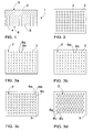
- Figures 3a to 3d show various cutting patterns 7 and cutting pattern formations by which the apertures 4 of the lower layer 3 may be formed in different embodiments.
- the cutting patterns are formed from two cuts 8a, 8b that proceed from substantially the same point in different directions.
- all cutting patterns 7 are formed in the same direction while in Figure 3b the cutting patterns 7 in the cutting pattern formation are arranged in two different directions.
Landscapes
- Engineering & Computer Science (AREA)
- Architecture (AREA)
- Structural Engineering (AREA)
- Civil Engineering (AREA)
- Physics & Mathematics (AREA)
- Acoustics & Sound (AREA)
- Electromagnetism (AREA)
- Thermal Sciences (AREA)
- Chemical & Material Sciences (AREA)
- Combustion & Propulsion (AREA)
- Mechanical Engineering (AREA)
- General Engineering & Computer Science (AREA)
- Building Environments (AREA)
- Floor Finish (AREA)
Abstract
Description
- The invention relates to an insulation structure for sound and heat insulation of floors.
- The invention further relates to a method of forming a floor insulation structure.
- Owing to their heat insulating properties in particular, EPS (Expanded Polystyrene) materials are commonly used in floor structures. However, a problem with these EPS materials is sound insulation. Indeed in practice, a vast majority of complaints about sound insulation problems concern the use of these EPS materials. Even if such EPS materials and floor structure solutions could meet the minimum requirements set e.g. by the Finnish building code for the impact sound level, i.e. structure-borne noise audible in other spaces, typically these solutions are not, however, sufficient as far as an attractive living environment is concerned.
- It is also known to use mineral wool in the insulation structures of floor structures. A mineral wool material is less expensive and has better sound insulation properties than an EPS material but, in conjunction with floor heating, its installation necessitates a steel wire net for fastening pipes, which makes the installation slower and more cumbersome.
- Comfort and energy saving factors, for instance, have contributed to the increasing popularity of floor heating in new buildings in particular. Various solutions for the installation of floor heating are known from
EP 0 346 529 ,DE 3 730 144DE 3 125 318 - An object of the present invention is to provide a novel and improved sound and heat insulation structure of floors.
- A method according to the invention is characterized by forming at least one layer of a substantially non-perforated and at least partially closed-cell foam plastic material, forming at least one layer of a perforated and at least partly closed-cell foam plastic material, and combining the layers to form an insulation structure or a part thereof.
- An insulation structure according to the invention is characterized in that the structure comprises at least two layers made from an at least partially closed-cell foam plastic material, wherein the layer that in an operating position is the upper layer is substantially non-perforated, and the layer that in the operation position is the lower layer is provided with apertures for reducing tension and tightness of the material in order to improve sound insulation properties of the structure.
- An idea underlying the invention is that the floor insulation structure comprises at least two layers formed from a closed-cell foam plastic material, and the layer that in an operating position is the lower layer is perforated. The perforation enables the tension and tightness of this lower layer to be reduced. The layer that in the operating position is the upper layer is substantially non-perforated, and these layers are combined to form an isolation structure or a part thereof.
- An advantage of the invention is that by reducing the tension and tightness of the layer that in the operating position is the lower layer, the perforation of the material may be used for significantly reducing the propagation of low-frequency sounds in particular in the material. When this layer is combined with another, substantially non-perforated layer, and when these layers are made from a closed-cell foam plastic material, a sound and heat insulation structure of floors is achieved that has good sound insulation properties also at low impact sound frequencies. This is advantageous particularly as far as the sound insulation of intermediate floors between flats or apartments is concerned, since it is particularly the low impact sound frequencies that typically cause most inconvenience and complaints.
- Some embodiments of the invention are described in closer detail in the accompanying drawings, in which
-
Figure 1 is a schematic side view showing a floor insulation structure, -
Figure 2 schematically shows a detail of a perforated layer, as seen from below, -
Figures 3a to 3d schematically show various cutting patterns in some perforated layers, as seen from below, -
Figure 4 schematically shows a detail of a cutting pattern formation stretched open, -
Figures 5a to 5b schematically show a detail of an embodiment wherein an insulation structure is used as an installation base for floor heating, inFigure 5a as seen from above and inFigure 5b in a direction of section A-A, and -
Figures 6a to 6b schematically show a detail of another embodiment wherein an insulation structure is used as an installation base for floor heating, inFigure 6a as seen from above and inFigure 6b in a direction of section B-B. - For the sake of clarity, the figures show some embodiments of the invention in a simplified manner, and the figures and/or details thereof are not in scale with one another. In the figures, like reference numerals identify like elements.
-
Figure 1 is a schematic side view showing aninsulation structure 1. The insulation structure comprises at least two layers: anupper layer 2 and alower layer 3. In different embodiments different layers may be added above, below, or between theupper layer 2 and thelower layer 3 as necessary and appropriate. Both theupper layer 2 and thelower layer 3 may be formed from an at least partly closed-cell foam plastic material, preferably from cross-linked or non-crosslinked partly or entirely closed-cell foam polyethylene. The material may thus be e.g. a closed-cell foam plastic material, or a combination of a closed-cell and open-cell foam plastic material. The materials of the layers may be mutually the same, or they may differ from one another in composition, structure, or in another corresponding manner. Theupper layer 2 may have a thickness of preferably 10 to 20 mm while thelower layer 3 may have a thickness of preferably 10 to 30 mm. - The layer that in the figure as well as in the real operating position is the
lower layer 3 of theinsulation structure 1 is provided with apertures. This reduces the tension and tightness of the material, which, in turn, reduces the conveyance of impact sounds in the material particularly at low frequencies, as compared with a corresponding material having no apertures. When the insulation structure is subjected to a load from above, the apertures enable the lower layer of the insulation material to yield laterally in the direction of the aperture. It is advantageous for a material to have a good resilience, i.e. when the insulation material yields on account of the load, it will quite quickly return to the shape it had before it was subjected to the load. - The layer that in the figure as well as in the real operating position is the
upper layer 2 of theinsulation structure 1 is substantially non-perforated. Thus, theupper layer 2 may have or, during installation, it may be provided with openings e.g. for floor heating fasteners; nevertheless, the material is still substantially uniform. When thelower layer 3 and theupper layer 2 are combined on top of one another as shown in the figure, the combination damps impact sounds of different types better than a perforated or non-perforated material as such. In addition, the substantially non-perforatedupper layer 2 forms a uniform surface e.g. for further installations, so the apertures of thelower layer 3 do not continue uniformly to anupper surface 5 of theinsulation structure 1. This is advantageous also e.g. when a layer of a material, such as a filler, concrete or the like, that is in a fluent form, such as in a powdery, granular, or fluid form, is to be arranged on top of theinsulation structure 1. In such a case, the fluent material is prevented from entering into the apertures, wherein it might deteriorate the operation of the apertures in sound insulation. - In terms of its material and dimensions, the insulation structure may be made such that it works better when a certain load is already provided thereabove. This load may be formed e.g. by a concrete layer to be arranged on top of the insulation structure. An appropriate load may be e.g. about 90 kg/m2.
-
Figure 2 shows a detail of alower layer 3, as seen from below. In such a case, the layer formed from an at least partly closed-cell foam plastic material is provided withapertures 4. Theseapertures 4 continue substantially through thelower layer 3 in the operating position from bottom to top, either perpendicularly with respect to alower surface 6, at an angle, or in another direction advantageous to a given purpose of use. -
Figures 3a to 3d showvarious cutting patterns 7 and cutting pattern formations by which theapertures 4 of thelower layer 3 may be formed in different embodiments. InFigures 3a and 3b , the cutting patterns are formed from twocuts Figure 3a , allcutting patterns 7 are formed in the same direction while inFigure 3b thecutting patterns 7 in the cutting pattern formation are arranged in two different directions. -
Figures 3c and 3d showcutting patterns 7 comprising threecuts cutting pattern 7 are easy to stretch to an open position, and the apertures thus formed are advantageous as far as sound insulation is concerned. In different embodiments, thecutting pattern 7 may comprise even more than three cuts. InFigure 3c , thecutting patterns 7 are arranged substantially separately, whereas inFigure 3d thecutting patterns 7 are arranged mutually partly overlappingly. Such an arrangement of thecutting patterns 7 at least partly overlappingly further improves the sound insulation properties of theinsulation structure 1. In addition, such an arrangement of the cutting patterns does not reduce the load bearing capacity of the material too much. - In different embodiments, the cutting
patterns 7 may be arranged in formations in one or more directions, and/or a cutting pattern formation may consist of one or more cutting pattern types 7. Further, in different embodiments, a circular opening may be arranged at a starting-point wherefromcuts -
Figure 4 schematically shows a detail of the cutting pattern formation shown inFigure 3d such that the cuttingpatterns 7 are stretched to an open position in order to formopen apertures 4. As discussed above, theapertures 4 should be open in the operation conditions of the insulation structure in order to reduce the tension and tightness of the material and thus in order to achieve as advantageous sound insulation properties as possible. Theapertures 4 formed by the cuttingpatterns 7 may be brought to the open position e.g. by stretching the cutting-patterned material such that theapertures 4 open, and by connecting the thus stretchedlower layer 3 e.g. by lamination to theupper layer 2, in which case theapertures 4 remain in the open position, or in another appropriate way, such as by laminating the apertures of thelower layer 3 into the open position prior to connecting it to theupper layer 2. -
Figure 5a schematically shows a detail of an embodiment as seen from above, wherein theinsulation structure 1 described in the present application is used as an installation base for floor heating. In this embodiment, afloor heating pipe 9 is connected to theupper surface 5 of theupper layer 2 of theinsulation structure 1 by using afastening tape 10 known per se. Thefastening tape 10 and, correspondingly, the part of theupper surface 5 of theupper layer 2 that is in contact with at least thefloor heating pipe 9 are made from materials which stick to one another, keeping thefloor heating pipe 9 fastened to theupper surface 5. This fastening manner is known per se, as is the fact that thefastening tape 10 may be connected to thefloor heating pipe 9 in a transverse manner, as shown inFigure 5a , or in another appropriate manner, such as in a longitudinal direction of thepipe 9, or by winding thepipe 9 spirally.Figure 5b schematically shows the corresponding detail in a direction of section A-A. -
Figure 5b schematically shows a detail of another embodiment as seen from above, wherein theinsulation structure 1 described in the present application is also used as an installation base for floor heating. In this embodiment, thefloor heating pipe 9 is fastened to theinsulation structure 1 by fasteners 11 known per se.Figure 6b schematically shows the corresponding detail in a direction of section B-B. The embodiments shown inFigures 5a to 5b and 6a to 6b are only examples of how thefloor heating pipes 9 may be connected to theinsulation structure 1. In different embodiments, different fastening manners known per se may also be combined as necessary. - In some embodiments, the
upper layer 2 may be provided with structures, such as grooves, for the installation offloor heating pipes 9. The grooves may be arranged in the insulation material e.g. by pressing or engraving. - In some cases, the features disclosed in the present application may be used as such, irrespective of other features. On the other hand, the features disclosed in the present invention may be combined in order to produce different combinations, when necessary.
- The drawings and the related description are only intended to illustrate the idea of the invention. The details of the invention may vary within the scope of the claims.
Claims (15)
- An insulation structure for sound and heat insulation of floors, characterized in that the structure comprises at least two layers made from an at least partially closed-cell foam plastic material, wherein the layer that in an operating position is the upper layer (2) is substantially non-perforated, and the layer that in the operation position is the lower layer (3) is provided with apertures (4) for reducing tension and tightness of the material in order to improve sound insulation properties of the structure.
- An insulation structure as claimed in claim 1, characterized in that the apertures (4) of the layer that in the operating position is the lower layer (3) are formed as cutting patterns (7) stretchable to an open position.
- An insulation structure as claimed in claim 2, characterized in that the cutting pattern (7) consists of at least two cuts (8a, 8b, 8c) that proceed from a substantially same point in different directions.
- An insulation structure as claimed in claim 2 or 3, characterized in that adjacent cutting patterns (7) are arranged at least partly overlappingly.
- An insulation structure as claimed in any one of the preceding claims, characterized in that the layers (2, 3) are made from cross-linked or non-crosslinked closed-cell foam polyethylene.
- An insulation structure as claimed in any one of the preceding claims, characterized in that the structure is an installation base for floor heating pipes (9).
- An insulation structure as claimed in claim 6, characterized in that the upper layer (2) is provided with structures, such as grooves, for installation of the floor heating pipes (9).
- A method of manufacturing a floor insulation structure, characterized by forming at least one layer of a substantially non-perforated and at least partially closed-cell foam plastic material, forming at least one layer of a perforated and at least partly closed-cell foam plastic material, and combining the layers to form an insulation structure (1) or a part thereof.
- A method as claimed in claim 8, characterized by forming apertures (4) of the perforated layer as cutting patterns (7).
- A method as claimed in claim 9, characterized by forming the cutting patterns (7) from at least two cuts (8a, 8b, 8c) which proceed from a substantially same point in different directions.
- A method as claimed in claim 9 or 10, characterized by arranging adjacent cutting patterns (7) at least partly overlappingly.
- A method as claimed in any one of claims 9 to 11, characterized by stretching the cutting patterns (7) in order to form the apertures (4).
- A method as claimed in claim 12, characterized by fastening a perforated layer in a stretched form to a non-perforated layer.
- A method as claimed in any one of claims 8 to 13, characterized by forming the layers from cross-linked or non-crosslinked closed-cell foam polyethylene.
- A method as claimed in any one of claims 8 to 14, characterized by the insulation structure (1) constituting an installation base for floor heating pipes (9).
Applications Claiming Priority (1)
| Application Number | Priority Date | Filing Date | Title |
|---|---|---|---|
| FI20095158A FI20095158A7 (en) | 2009-02-19 | 2009-02-19 | Floor insulation structure |
Publications (2)
| Publication Number | Publication Date |
|---|---|
| EP2221433A2 true EP2221433A2 (en) | 2010-08-25 |
| EP2221433A3 EP2221433A3 (en) | 2016-12-07 |
Family
ID=40404657
Family Applications (1)
| Application Number | Title | Priority Date | Filing Date |
|---|---|---|---|
| EP10153971.6A Withdrawn EP2221433A3 (en) | 2009-02-19 | 2010-02-18 | Floor insulation structure |
Country Status (2)
| Country | Link |
|---|---|
| EP (1) | EP2221433A3 (en) |
| FI (1) | FI20095158A7 (en) |
Cited By (3)
| Publication number | Priority date | Publication date | Assignee | Title |
|---|---|---|---|---|
| EP2554091A1 (en) * | 2011-08-01 | 2013-02-06 | Faist Chem Tec GmbH | Acoustic baffling sandwich board with perforation |
| DE202015100914U1 (en) * | 2015-02-12 | 2016-05-13 | Uponor Innovation Ab | Insulation mat and heat exchanger arrangement |
| DE102017004000A1 (en) * | 2017-04-26 | 2018-10-31 | Ewald Dörken Ag | decoupling membrane |
Citations (3)
| Publication number | Priority date | Publication date | Assignee | Title |
|---|---|---|---|---|
| DE3125318A1 (en) | 1981-06-27 | 1983-01-27 | Roth Werke Gmbh, 3563 Dautphetal | Retaining means for fixing a heating pipe of a floor-heating system |
| DE3730144A1 (en) | 1986-09-09 | 1988-04-21 | Hewing Gmbh & Co | Mounting plate for a panel heating system |
| EP0346529A1 (en) | 1988-06-04 | 1989-12-20 | Wirsbo Pex G.m.b.H. | Pipe mounting |
Family Cites Families (3)
| Publication number | Priority date | Publication date | Assignee | Title |
|---|---|---|---|---|
| JP2002357328A (en) * | 2001-03-30 | 2002-12-13 | Kanegafuchi Chem Ind Co Ltd | Floor heating panel and method of manufacturing the same |
| JP2002371702A (en) * | 2001-06-18 | 2002-12-26 | Kanegafuchi Chem Ind Co Ltd | Composite panel and method of manufacturing the same |
| DE102004018550B4 (en) * | 2004-04-14 | 2013-10-31 | Gefinex Gmbh | Polyethylene foams with low dynamic stiffness |
-
2009
- 2009-02-19 FI FI20095158A patent/FI20095158A7/en not_active IP Right Cessation
-
2010
- 2010-02-18 EP EP10153971.6A patent/EP2221433A3/en not_active Withdrawn
Patent Citations (3)
| Publication number | Priority date | Publication date | Assignee | Title |
|---|---|---|---|---|
| DE3125318A1 (en) | 1981-06-27 | 1983-01-27 | Roth Werke Gmbh, 3563 Dautphetal | Retaining means for fixing a heating pipe of a floor-heating system |
| DE3730144A1 (en) | 1986-09-09 | 1988-04-21 | Hewing Gmbh & Co | Mounting plate for a panel heating system |
| EP0346529A1 (en) | 1988-06-04 | 1989-12-20 | Wirsbo Pex G.m.b.H. | Pipe mounting |
Cited By (3)
| Publication number | Priority date | Publication date | Assignee | Title |
|---|---|---|---|---|
| EP2554091A1 (en) * | 2011-08-01 | 2013-02-06 | Faist Chem Tec GmbH | Acoustic baffling sandwich board with perforation |
| DE202015100914U1 (en) * | 2015-02-12 | 2016-05-13 | Uponor Innovation Ab | Insulation mat and heat exchanger arrangement |
| DE102017004000A1 (en) * | 2017-04-26 | 2018-10-31 | Ewald Dörken Ag | decoupling membrane |
Also Published As
| Publication number | Publication date |
|---|---|
| EP2221433A3 (en) | 2016-12-07 |
| FI20095158L (en) | 2010-08-20 |
| FI20095158A0 (en) | 2009-02-19 |
| FI20095158A7 (en) | 2010-08-20 |
Similar Documents
| Publication | Publication Date | Title |
|---|---|---|
| CA2455438C (en) | Building panel | |
| CN207032561U (en) | A kind of sound-proof wall body structure | |
| KR101760079B1 (en) | Noise reduction method between floors in reinforced concrete buildings | |
| KR20010112682A (en) | Composite floor for waterproof and heat-insulation and the constructing method of the same | |
| KR101479167B1 (en) | Reduce noise floors and structure reduce noise between floors of building | |
| KR101238751B1 (en) | a soundproof mat and establishment method thereof | |
| KR20160081643A (en) | Sound insulation structure for splitting plane of apartment house and construction method thereof | |
| JP3914033B2 (en) | Anti-vibration and heat insulation floor structure for buildings | |
| EP3042003B1 (en) | Building element with first and second cover layers and intermediate core having two different materials | |
| KR100763434B1 (en) | Interlayer Noiseproof Flooring | |
| JP6434760B2 (en) | Sound insulation floor structure | |
| KR102553306B1 (en) | Composite floor system for reducing interlayer noise | |
| CN202117188U (en) | Cement porous-polymer composite thermal-insulation board | |
| KR100470327B1 (en) | Wood flooring structure which is made of elastic sound absorbing materials | |
| KR20160046047A (en) | Sound absorption panel and Floor structure including the same | |
| JP5131731B2 (en) | Roof insulation | |
| CN102336548A (en) | Cement porous polymer composite heat insulation plate | |
| KR101549921B1 (en) | The vibration insulation for reduce noise prevention between floors for building and construction method using the same | |
| KR100523806B1 (en) | a heat insulating and impacting sound reducing material for a multi-storey building | |
| KR102756163B1 (en) | Laminated panel for reducing vibration and noise between floors and its construction method | |
| KR101357023B1 (en) | Construction method for fixing noise protection mat between floors | |
| KR20050067789A (en) | Structure for reducing noises between floors | |
| KR20050054217A (en) | Noise isolation pads of a floor | |
| KR100786807B1 (en) | Ondol floor structure with improved sound insulation and insulation | |
| KR102801124B1 (en) | Single panel type inter-floor noise buffer for blocking floor impact sound |
Legal Events
| Date | Code | Title | Description |
|---|---|---|---|
| PUAI | Public reference made under article 153(3) epc to a published international application that has entered the european phase |
Free format text: ORIGINAL CODE: 0009012 |
|
| AK | Designated contracting states |
Kind code of ref document: A2 Designated state(s): AT BE BG CH CY CZ DE DK EE ES FI FR GB GR HR HU IE IS IT LI LT LU LV MC MK MT NL NO PL PT RO SE SI SK SM TR |
|
| AX | Request for extension of the european patent |
Extension state: AL BA RS |
|
| RAP1 | Party data changed (applicant data changed or rights of an application transferred) |
Owner name: UPONOR INNOVATION AB |
|
| PUAL | Search report despatched |
Free format text: ORIGINAL CODE: 0009013 |
|
| AK | Designated contracting states |
Kind code of ref document: A3 Designated state(s): AT BE BG CH CY CZ DE DK EE ES FI FR GB GR HR HU IE IS IT LI LT LU LV MC MK MT NL NO PL PT RO SE SI SK SM TR |
|
| AX | Request for extension of the european patent |
Extension state: AL BA RS |
|
| RIC1 | Information provided on ipc code assigned before grant |
Ipc: E04F 15/18 20060101AFI20161028BHEP Ipc: F24D 3/14 20060101ALI20161028BHEP |
|
| STAA | Information on the status of an ep patent application or granted ep patent |
Free format text: STATUS: THE APPLICATION IS DEEMED TO BE WITHDRAWN |
|
| 18D | Application deemed to be withdrawn |
Effective date: 20170608 |