EP2221214A1 - Dual use transport vehicle - Google Patents
Dual use transport vehicle Download PDFInfo
- Publication number
- EP2221214A1 EP2221214A1 EP09152648A EP09152648A EP2221214A1 EP 2221214 A1 EP2221214 A1 EP 2221214A1 EP 09152648 A EP09152648 A EP 09152648A EP 09152648 A EP09152648 A EP 09152648A EP 2221214 A1 EP2221214 A1 EP 2221214A1
- Authority
- EP
- European Patent Office
- Prior art keywords
- bag
- floor
- load
- mezzanine floor
- vehicle according
- Prior art date
- Legal status (The legal status is an assumption and is not a legal conclusion. Google has not performed a legal analysis and makes no representation as to the accuracy of the status listed.)
- Granted
Links
Images


Classifications
-
- B—PERFORMING OPERATIONS; TRANSPORTING
- B60—VEHICLES IN GENERAL
- B60P—VEHICLES ADAPTED FOR LOAD TRANSPORTATION OR TO TRANSPORT, TO CARRY, OR TO COMPRISE SPECIAL LOADS OR OBJECTS
- B60P3/00—Vehicles adapted to transport, to carry or to comprise special loads or objects
- B60P3/42—Vehicles adapted to transport, to carry or to comprise special loads or objects convertible from one use to a different one
- B60P3/426—Vehicles adapted to transport, to carry or to comprise special loads or objects convertible from one use to a different one from transport of fluids to transport of other types of goods
Definitions
- the invention is related to a transport vehicle, comprising a chassis provided with wheels, a load compartment on said chassis and provided with a load floor, longitudinal side walls which extend upwardly with respect to the load floor, a bulkhead at the front, at least one load door at the back, as well as a roof, wherein a mezzanine floor is provided in the load compartment above the load floor, lifting means which cooperate with the mezzanine floor for adjusting the height of said mezzanine floor with respect to the load floor, as well as a closed flexible bag for containing a fluid, said bag having a lower surface and an upper surface, said lower surface of the bag being supported in the load compartment and said upper surface of the bag being freely supported above said lower surface in dependence on the contents of the bag.
- Such transport vehicles are known. As a result of their ability to be converted into either a vehicle which is fit for transporting a liquid, or into a vehicle which is fit for transporting other goods, in particular packed goods, parcels and the like, they provide a high degree of operational efficiency.
- tank vehicles were only capable of transporting bulk goods, in particular liquid bulk goods, which often meant that no return loads other than (the same) liquid could be handled. This severely limited the usefulness of said traditional tank vehicles.
- a flexible bag on the load floor of the vehicle.
- a mezzanine floor is provided which is displaceable between a high position an a low position.
- the mezzanine floor is lifted into the high position. Possibly, some goods are placed on said mezzanine floor.
- the centre of gravity of the liquid load is at such low position as well which is advantageous for the stability of the loaded vehicle.
- the mezzanine floor is lowered while the bag is in a collapsed state. A larger amount of goods can then be stored in the load compartment.
- a mezzanine floor is provided in the load compartment of a transport vehicle, together with a rigid, metal tank on top of the mezzanine floor.
- the tank In the lowered position of the mezzanine floor, the tank will be able to receive a liquid. The centre of gravity of the load is thus at a relatively low position.
- the mezzanine floor together with tank is lifted. The load floor thus becomes available for receiving these goods.
- the disadvantage of this arrangement is that the volume which becomes available after lifting the mezzanine floor, remains limited. The tank still takes a considerable space above the lifted mezzanine floor, which goes at the expense of the space below the mezzanine floor. Thus, problems arise when moving the goods over the load floor, and moreover the stacking height is small.
- the object of the invention is to provide a transport vehicle of the type described before for dual uses, which lacks the disadvantages described before and which provides a largely unobstructed load compartment in the raised position of the mezzanine floor for accommodating packed goods. Said object is achieved in that the lower surface of the flexible bag is positioned on top of the mezzanine floor.
- the position of the flexible bag on top of the mezzanine floor provides a combination of advantages which increases the operational efficiency of the transport vehicle in question considerably.
- the availability of the flexible bag within the load compartment makes it possible to convert the transport vehicle into a liquid tanker.
- the mezzanine floor is lowered on top of the load floor, after which the flexible bag can be filled with liquid.
- the flexible bag may be of a size which is similar to the size of the mezzanine floor or the load floor, a large amount of liquid can be accommodated.
- the flexible bag may have a capacity of 24.000 liters of liquid, which amounts to a payload of about 24 tons. Flexible bags having other capacities may however be used as well.
- several bags may be placed next to each other on top of the mezzanine floor. In that case, preferably such bags adjoin each other so as to fully occupy the space available on the mezzanine floor.
- the centre of gravity of the liquid load is at the lowest possible level, which greatly contributes to the stability of the transport vehicle.
- the transport vehicle is quite well fit for parcels or packed goods as well.
- the mezzanine floor with the emptied flexible bag is then lifted to a high position directly beneath the roof of the load compartment.
- the combined height of the floor and bag is fairly low which means that height of the load compartment, measured from the load floor to the underside of the lifted mezzanine floor, is only a fraction smaller than the total height of the load compartment.
- the useful transport space within the load compartment is hardly affected, which means that any goods can be accommodated therein.
- the standard load floor becomes available for positioning the packed goods thereon.
- the loads can be handled at a normal height, which is of importance while moving the loads by means of e.g. a forklift truck.
- moving the loads within the load compartment itself is also possible as a result of the height available within the load compartment.
- the mezzanine floor with flexible bag can be installed in any standard transport vehicle, such as a trailer. Additionally, in the lifted position the vulnerable flexible bag is well protected against damage having regard to the fact that the packed goods are at a lower level.
- the flexible bag may comprise a flexible material such as rubber or plastic.
- the bag is closed in itself, and may be provided with a fluid valve for filling and emptying the bag.
- the fluid valve is at the back of the bag near the load door(s). This contributes to the ease of filling and emptying the bag.
- the mezzanine floor is preferably provided with a recess in which the valve is accommodated. When lifting the mezzanine floor up to and against the roof of the load compartment, the valve, which may be rather bulky, will not hamper the upward movement of the mezzanine floor as it will be accommodated within said recess of the mezzanine floor.
- the bag In the case of a trailer, the bag has an elongate shape which largely conforms the shape of the load floor of the trailer.
- the mezzanine floor may comprise upstanding longitudinal side edges. Also, these upstanding edges will protect the bag with respect to contact with the longitudinal side walls of the load compartment, thus preventing frictional wear of the bag. Also, tie wraps may be provided which extend over the bag and the ends of which are connected to opposite longitudinal sides of the mezzanine floor.
- the means for lifting and lowering the mezzanine floor and bag should preferable occupy as little space as possible, so as to guarantee a maximum load capacity of the load compartment.
- the lifting means preferably comprise flexible pulling members, such as straps, one end of which is connected to the mezzanine floor and the other end of which is wound on a respective winch element.
- these pulling members, together with corresponding winch elements are distributed at regular intervals along the longitudinal side walls, so as to provide for a reliable handling of the mezzanine floor.
- the winch elements are located as close to the roof of the load compartment as possible in order to reach the maximum lifting height of the mezzanine floor and thereby the maximum height between the load floor and the lifted mezzanine floor.
- the winch elements can be operated in a uniform way, for instance by interconnecting these through a torsion rod.
- the torsion rod may be driven in rotation through any suitable drive source, such as an electric motor or a hydraulic motor. Preference is given to a hydraulic motor, as the torsion rods, and thus the mezzanine floor, can then be simply immobilized by closing the hydraulic circuit.
- each torsion rod may engage a transversely extending drive rod through a tooth wheel transmission, said drive rod being connected to a hydraulic or electric motor.
- other interconnection means may be provided as well, such as electric interconnections.
- the side walls may comprise upwardly extending mounting rails.
- a support bar By means of a support bar, can be connected to pairs of opposite mounting rails, the mezzanine floor can be supported.
- the valve is preferable positioned at the back of the bag, near the load compartment doors. Emptying of the bag is obtained by opening the valve, which makes the liquid simply flow out of the bag under the influence of gravity.
- the bag can be emptied fully by applying a method which comprises the steps of:
- the tilting motion of the mezzanine floor can be obtained in various ways, for instance by individually driving the winch elements. However, preference is given to a fairly simple approach, which comprises the steps of:
- WO-00/03893 discloses a bulk goods transport vehicle with an open topped body.
- a bladder which is connected to the open top, can be deployed downwardly into the body so as to avoid cross-contamination.
- the load compartment of said prior art transport vehicle does not have load doors at the back, and is therefore not fit for transporting packed goods such as parcels.
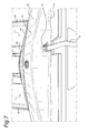
- FIG. 1 shows an example of a transport vehicle which has been equipped with a mezzanine floor and flexible bag according to the invention.
- Said transport vehicle consists of a truck 1 and trailer 2.
- Said trailer 2 consists of the load compartment 3 and the chassis 4 which is provided with wheels 5.
- the truck 1 and the trailer 2 are connected to each other in a traditional way by means of well-known coupling means (not shown) which allow relative rotations.
- the load compartment 3 consists of the longitudinal side walls 6, the load floor 7, the roof 8, the front bulkhead 9 and the back doors 10 which have been swung about the hinges 11 into in the fully open position in figure 2 , against the outside of the longitudinal side walls 6.
- a heating device 35 has been mounted on the outside of the front bulkhead, for heating the load compartment 3 as will be explained hereunder.
- the mezzanine floor 12 has been provided. Said mezzanine floor supports the closed flexible bag 13.
- the lower surface 14 of said flexible bag 13 rests on top of the mezzanine floor of 12.
- the upper surface 15 of said flexible bag 13 is freely supported above the lower surface 14.
- the flexible bag 13 is empty which means that the upper surface 15 rests on the lower surface 14.
- the flexible bag 13 has been filled with a liquid through hose 16 connected to the valve 17 of the flexible bag 13.
- the upper surface 15 is supported at a distance above the lower surface 14, in dependence on the amount of liquid which has been introduced into the bag 13.
- a vent 34 has been provided for releasing gases from the flexible back 13 during the process of filling thereof.
- the mezzanine floor 12 is supported from the roof 8 by means of the flexible straps 18 which are each wound on a winch element 19.
- a winch element 19 As can be seen in figure 3 , in this embodiment four of these winch elements 19 and four straps have been provided along each longitudinal side wall 6 of the load compartment 3. Of course, depending on the length of the load compartment and the weight to be supported, more or less of these winch elements and straps can be applied.
- the winch elements 19 each fixed on one of the torsion rods 20 which run next to the longitudinal side walls 6, and which are rotatably supported with respect to the roof 8 by means of bearing blocks 21.
- the roof has been provided with a heat distributing duct 36. Said duct is fed with heated air form the heating device 35 which is mounted on the outside of the front bulkhead 9, as mentioned before. Thus, the load compartment 3 can be heated as desired.
- the heat distributing duct 36 is of a limited height, in such a way that it does not interfere with the upward movement of the mezzanine floor 12.
- the torsion rods 20 are interconnected through the transversely extending drive rod 22 and the gear transmissions 23.
- the drive rod 22 itself is driven by the hydraulic motor 24 through the gear transmission 25.
- the mezzanine floor 12 together with the flexible bag 13 can be moved up and down, as desired.
- the mezzanine floor 12 can be locked in any desired position.
- tie wraps 26 extend over the flexible bag 13. These tie wraps 26 are each connected to opposite edges of the mezzanine floor 12, so as to stabilize the filled flexible bag 13 as shown in figure 7 .
- the flexible black 13 can be held reliably with respect to the mezzanine floor 12.
- the mezzanine floor 12 has longitudinal upstanding edges 27 which furthermore have a stabilizing effect on the flexible bag 13.
- brackets 28 have been welded onto which the straps 19 are connected.
- the mezzanine floor 12 comprises a recess 29 for accommodating the valve 17, in particular in the raised position thereof as shown in figure 2 .
- the longitudinal side walls 6 are provided with mounting rails 32. Between two opposite mounting rails 32, a support bar 33 can be applied as shown in figure 2 .
- the mezzanine floor 12 can be secured in a desired location.
- the mezzanine floor 12 has been secured in the uppermost position, it is also possible to apply the support bars 33 at a lower position, for providing additional loading space on top of the mezzanine floor after removing the flexible bag.
Landscapes
- Engineering & Computer Science (AREA)
- Health & Medical Sciences (AREA)
- Public Health (AREA)
- Transportation (AREA)
- Mechanical Engineering (AREA)
- Body Structure For Vehicles (AREA)
- Bag Frames (AREA)
Abstract
Description
- The invention is related to a transport vehicle, comprising a chassis provided with wheels, a load compartment on said chassis and provided with a load floor, longitudinal side walls which extend upwardly with respect to the load floor, a bulkhead at the front, at least one load door at the back, as well as a roof, wherein a mezzanine floor is provided in the load compartment above the load floor, lifting means which cooperate with the mezzanine floor for adjusting the height of said mezzanine floor with respect to the load floor, as well as a closed flexible bag for containing a fluid, said bag having a lower surface and an upper surface, said lower surface of the bag being supported in the load compartment and said upper surface of the bag being freely supported above said lower surface in dependence on the contents of the bag.
- Such transport vehicles are known. As a result of their ability to be converted into either a vehicle which is fit for transporting a liquid, or into a vehicle which is fit for transporting other goods, in particular packed goods, parcels and the like, they provide a high degree of operational efficiency. Traditionally, tank vehicles were only capable of transporting bulk goods, in particular liquid bulk goods, which often meant that no return loads other than (the same) liquid could be handled. This severely limited the usefulness of said traditional tank vehicles.
- According to the state of the art as disclosed in
EP-A-763.459 - The disadvantage of such arrangement is that, even in the lowered state, the mezzanine floor is still at a considerable distance above the load floor of the compartment, having regard to the fact that the collapsed bag still takes some space. Consequently, it is difficult to load or unload the mezzanine floor, because loading devices such as a fork lift are obliged to operate at a fairly high level. Moreover, although the bag is covered by the mezzanine floor, it is still in a somewhat vulnerable position. The bag may easily become damaged by objects which fall off the mezzanine floor.
- According to another proposal as disclosed in
DE-U-20.2006.002.564 , a mezzanine floor is provided in the load compartment of a transport vehicle, together with a rigid, metal tank on top of the mezzanine floor. In the lowered position of the mezzanine floor, the tank will be able to receive a liquid. The centre of gravity of the load is thus at a relatively low position. In case other goods than liquids are to be transported, the mezzanine floor together with tank is lifted. The load floor thus becomes available for receiving these goods. The disadvantage of this arrangement is that the volume which becomes available after lifting the mezzanine floor, remains limited. The tank still takes a considerable space above the lifted mezzanine floor, which goes at the expense of the space below the mezzanine floor. Thus, problems arise when moving the goods over the load floor, and moreover the stacking height is small. - The object of the invention is to provide a transport vehicle of the type described before for dual uses, which lacks the disadvantages described before and which provides a largely unobstructed load compartment in the raised position of the mezzanine floor for accommodating packed goods. Said object is achieved in that the lower surface of the flexible bag is positioned on top of the mezzanine floor.
- The position of the flexible bag on top of the mezzanine floor provides a combination of advantages which increases the operational efficiency of the transport vehicle in question considerably. The availability of the flexible bag within the load compartment makes it possible to convert the transport vehicle into a liquid tanker. The mezzanine floor is lowered on top of the load floor, after which the flexible bag can be filled with liquid. As the flexible bag may be of a size which is similar to the size of the mezzanine floor or the load floor, a large amount of liquid can be accommodated. As an example, the flexible bag may have a capacity of 24.000 liters of liquid, which amounts to a payload of about 24 tons. Flexible bags having other capacities may however be used as well. Also, several bags may be placed next to each other on top of the mezzanine floor. In that case, preferably such bags adjoin each other so as to fully occupy the space available on the mezzanine floor. Always, the centre of gravity of the liquid load is at the lowest possible level, which greatly contributes to the stability of the transport vehicle.
- Conversely, the transport vehicle is quite well fit for parcels or packed goods as well. The mezzanine floor with the emptied flexible bag is then lifted to a high position directly beneath the roof of the load compartment. As the flexible bag is in the collapsed state, the combined height of the floor and bag is fairly low which means that height of the load compartment, measured from the load floor to the underside of the lifted mezzanine floor, is only a fraction smaller than the total height of the load compartment. Thus, the useful transport space within the load compartment is hardly affected, which means that any goods can be accommodated therein.
- Furthermore, in the lifted state of the mezzanine floor and bag, the standard load floor becomes available for positioning the packed goods thereon. Thus, the loads can be handled at a normal height, which is of importance while moving the loads by means of e.g. a forklift truck. Moreover, moving the loads within the load compartment itself is also possible as a result of the height available within the load compartment. The mezzanine floor with flexible bag can be installed in any standard transport vehicle, such as a trailer. Additionally, in the lifted position the vulnerable flexible bag is well protected against damage having regard to the fact that the packed goods are at a lower level.
- The flexible bag may comprise a flexible material such as rubber or plastic. The bag is closed in itself, and may be provided with a fluid valve for filling and emptying the bag. Preferably, the fluid valve is at the back of the bag near the load door(s). This contributes to the ease of filling and emptying the bag. The mezzanine floor is preferably provided with a recess in which the valve is accommodated. When lifting the mezzanine floor up to and against the roof of the load compartment, the valve, which may be rather bulky, will not hamper the upward movement of the mezzanine floor as it will be accommodated within said recess of the mezzanine floor. In the case of a trailer, the bag has an elongate shape which largely conforms the shape of the load floor of the trailer.
- With the aim of stabilizing the filled bag, the mezzanine floor may comprise upstanding longitudinal side edges. Also, these upstanding edges will protect the bag with respect to contact with the longitudinal side walls of the load compartment, thus preventing frictional wear of the bag. Also, tie wraps may be provided which extend over the bag and the ends of which are connected to opposite longitudinal sides of the mezzanine floor.
- The means for lifting and lowering the mezzanine floor and bag should preferable occupy as little space as possible, so as to guarantee a maximum load capacity of the load compartment. To that end, the lifting means preferably comprise flexible pulling members, such as straps, one end of which is connected to the mezzanine floor and the other end of which is wound on a respective winch element. Several of these pulling members, together with corresponding winch elements, are distributed at regular intervals along the longitudinal side walls, so as to provide for a reliable handling of the mezzanine floor. Preferable, the winch elements are located as close to the roof of the load compartment as possible in order to reach the maximum lifting height of the mezzanine floor and thereby the maximum height between the load floor and the lifted mezzanine floor.
- The winch elements can be operated in a uniform way, for instance by interconnecting these through a torsion rod. The torsion rod may be driven in rotation through any suitable drive source, such as an electric motor or a hydraulic motor. Preference is given to a hydraulic motor, as the torsion rods, and thus the mezzanine floor, can then be simply immobilized by closing the hydraulic circuit.
- The torsion rods at both longitudinal side walls of the load compartment may be interconnected in order to obtain a uniform movement of the mezzanine floor. To that end, each torsion rod may engage a transversely extending drive rod through a tooth wheel transmission, said drive rod being connected to a hydraulic or electric motor. However, other interconnection means may be provided as well, such as electric interconnections.
- After the mezzanine floor and the flexible bag have been lifted, they may be locked in that position by separate locking means. In this connection, the side walls may comprise upwardly extending mounting rails. By means of a support bar, can be connected to pairs of opposite mounting rails, the mezzanine floor can be supported.
- As mentioned before, the valve is preferable positioned at the back of the bag, near the load compartment doors. Emptying of the bag is obtained by opening the valve, which makes the liquid simply flow out of the bag under the influence of gravity. However, in the case of a fairly long bag, as may occur in long trailers, some of the liquid tends to remain within the bag as the valve is simply too far away. Still, the bag can be emptied fully by applying a method which comprises the steps of:
- operating the lifting means while the bag is filled with said fluid,
- during said operation of the lifting means, making the mezzanine floor tilt towards the fluid valve,
- opening the fluid valve and making the fluid flow towards said valve under the influence of the tilted position of the bag.
- The tilting motion of the mezzanine floor can be obtained in various ways, for instance by individually driving the winch elements. However, preference is given to a fairly simple approach, which comprises the steps of:
- providing, on each longitudinal side wall, a pulling member relatively close to the front wall which is shorter than a pulling member further away from said front wall,
- making the mezzanine floor tilt as a result of the length differences of said pulling members.
- Reference is furthermore made to the state of the art as disclosed in
FR-A-900.012 -
WO-00/03893 - The invention will now be described further with reference to the embodiment shown in the drawings.
-
Figure 1 shows the a truck with trailer according to the invention. -
Figure 2 shows a view from the back of the trailer with open back doors while the mezzanine floor is in the uppermost position. -
Figure 3 shows a view similar tofigure 2 , with the mezzanine floor in an intermediate position. -
Figure 4 shows the mezzanine floor in the fully lowered position. -
Figure 5 shows a view of the ceiling of the load compartment of the trailer, with a hydraulic drive. -
Figure 6 shows a view of the mezzanine floor in the tilted position. -
Figure 7 shows the view of the flexible bag filled with a liquid. -
Figure 1 shows an example of a transport vehicle which has been equipped with a mezzanine floor and flexible bag according to the invention. Said transport vehicle consists of atruck 1 andtrailer 2. Saidtrailer 2 consists of theload compartment 3 and the chassis 4 which is provided withwheels 5. Furthermore, thetruck 1 and thetrailer 2 are connected to each other in a traditional way by means of well-known coupling means (not shown) which allow relative rotations. - As furthermore shown in
figure 2 , theload compartment 3 consists of thelongitudinal side walls 6, theload floor 7, theroof 8, thefront bulkhead 9 and theback doors 10 which have been swung about thehinges 11 into in the fully open position infigure 2 , against the outside of thelongitudinal side walls 6. A heating device 35 has been mounted on the outside of the front bulkhead, for heating theload compartment 3 as will be explained hereunder. - Within the
load compartment 3, themezzanine floor 12 has been provided. Said mezzanine floor supports the closedflexible bag 13. In particular, thelower surface 14 of saidflexible bag 13 rests on top of the mezzanine floor of 12. Theupper surface 15 of saidflexible bag 13 is freely supported above thelower surface 14. In the situation shown infigures 2-4 and6 , theflexible bag 13 is empty which means that theupper surface 15 rests on thelower surface 14. However, in the position as shown infigure 7 , theflexible bag 13 has been filled with a liquid throughhose 16 connected to thevalve 17 of theflexible bag 13. In this position, theupper surface 15 is supported at a distance above thelower surface 14, in dependence on the amount of liquid which has been introduced into thebag 13. Avent 34 has been provided for releasing gases from the flexible back 13 during the process of filling thereof. - Now turning to the
figures 3 and4 , themezzanine floor 12 is supported from theroof 8 by means of theflexible straps 18 which are each wound on awinch element 19. As can be seen infigure 3 , in this embodiment four of thesewinch elements 19 and four straps have been provided along eachlongitudinal side wall 6 of theload compartment 3. Of course, depending on the length of the load compartment and the weight to be supported, more or less of these winch elements and straps can be applied. Thewinch elements 19 each fixed on one of thetorsion rods 20 which run next to thelongitudinal side walls 6, and which are rotatably supported with respect to theroof 8 by means of bearing blocks 21. - The roof has been provided with a heat distributing duct 36. Said duct is fed with heated air form the heating device 35 which is mounted on the outside of the
front bulkhead 9, as mentioned before. Thus, theload compartment 3 can be heated as desired. The heat distributing duct 36 is of a limited height, in such a way that it does not interfere with the upward movement of themezzanine floor 12. - As shown in
figure 5 , thetorsion rods 20 are interconnected through the transversely extendingdrive rod 22 and thegear transmissions 23. Thedrive rod 22 itself is driven by thehydraulic motor 24 through thegear transmission 25. By energizing thehydraulic motor 24, themezzanine floor 12 together with theflexible bag 13 can be moved up and down, as desired. By closing the hydraulic lines which feed thehydraulic motor 24, themezzanine floor 12 can be locked in any desired position. - As also shown in
figure 4 , tie wraps 26 extend over theflexible bag 13. These tie wraps 26 are each connected to opposite edges of themezzanine floor 12, so as to stabilize the filledflexible bag 13 as shown infigure 7 . By tensioning the tie wraps 26, the flexible black 13 can be held reliably with respect to themezzanine floor 12. As furthermore shown infigure 6 , themezzanine floor 12 has longitudinalupstanding edges 27 which furthermore have a stabilizing effect on theflexible bag 13. Onto theupstanding edges 27,brackets 28 have been welded onto which thestraps 19 are connected. As also clearly visible infigure 6 , themezzanine floor 12 comprises arecess 29 for accommodating thevalve 17, in particular in the raised position thereof as shown infigure 2 . - For the purposes of completely emptying the
flexible bag 13 through thevalve 17, it is desirable to tilt themezzanine floor 12 in such a way that the back of themezzanine floor 12 is at a lower level than the front thereof. Such tilting position can be obtained by providing extension pieces in the form ofchains front wall 9 of theload compartment 3 are directly connected to thecorresponding brackets 28. Seen from thefront wall 9, thesecond straps 19 are provided with a relativelyshort chain 30, and thethird straps 19 are provided with a somewhatlonger chain 31. Through thesechains third straps 19 are connected to thecorresponding brackets 28. The fourth straps remain loose. By now energizing thehydraulic motor 24, the front part of themezzanine floor 12 is lifted over a greater distance than the back part of themezzanine floor 12, thus promoting the flow of liquid within the flexible back 13 towards and through thevalve 17. - As shown in
figures 3 and4 , thelongitudinal side walls 6 are provided with mountingrails 32. Between two opposite mountingrails 32, asupport bar 33 can be applied as shown infigure 2 . By means of these support bars 32, themezzanine floor 12 can be secured in a desired location. Although infigure 2 themezzanine floor 12 has been secured in the uppermost position, it is also possible to apply the support bars 33 at a lower position, for providing additional loading space on top of the mezzanine floor after removing the flexible bag. -
- 1. Truck
- 2. Trailer
- 3. Load compartment
- 4. Chassis
- 5. Wheels
- 6. Longitudinal side wall
- 7. Load floor
- 8. Roof
- 9. Front wall
- 10. Backdoor
- 11. Hinge
- 12. Mezzanine floor
- 13. Flexible bag
- 14. Bottom wall flexible bag
- 15. Top wall flexible bag
- 16. Hose
- 17. Valve
- 18. Strap
- 19. Winch
- 20. Torsion rod
- 21. Bearing block
- 22. Drive rod
- 23. Gear transmission
- 24. Hydraulic motor
- 25. Gear transmission
- 26. Tie wrap
- 27. Upstanding edge mezzanine floor
- 28. Bracket
- 29. Recess mezzanine floor
- 30. Relatively short chain
- 31. Relatively long chain
- 32. Mounting rail
- 33. Support bar
- 34. Vent
- 35. Heating device
- 36. Heat distributing duct
Claims (15)
- Transport vehicle, comprising a chassis (4) provided with wheels (5), a load compartment (3) on said chassis (4) and provided with a load floor (7), longitudinal side walls (6) which extend upwardly with respect to the load floor, a bulkhead (9) at the front, at least one load door (10) at the back, as well as a roof (8), wherein a mezzanine floor (12) is provided in the load compartment (3) above the load floor (7), lifting means (18-25) which cooperate with the mezzanine floor (12) for adjusting the height of said mezzanine floor with respect to the load floor, as well as a closed flexible bag (13) for containing a fluid, said bag having a lower surface (14) and an upper surface (15), said lower surface (14) of the bag (13) being supported in the load compartment (3) and said upper surface (15) of the bag being freely supported above said lower surface (14) in dependence on the contents of the bag (13), characterized in that the flexible bag (13) is positioned on top of the mezzanine floor (12).
- Vehicle according to claim 1, wherein the bag (13) comprises a flexible material, such as rubber or plastic.
- Vehicle according to claim 1 or 2, wherein the bag (13) is provided with a fluid valve (17) for filling and emptying the bag.
- Vehicle according to claim 3, wherein the fluid valve (17) is at the back of the bag near the load door(s) (10).
- Vehicle according to claim 3 or 4, wherein the mezzanine floor (12) is provided with a recess (29) in which the valve (17) is accommodated.
- Vehicle according to any of the preceding claims, wherein the bag (13) has a vent (34) for venting air or gas which is contained in the bag.
- Vehicle according to any of the preceding claims, wherein the mezzanine floor (12) comprises upstanding longitudinal side edges (27).
- Vehicle according to any of the preceding claims, wherein tie wraps (26) are provided which extend over the bag (13) and the ends of which are connected to opposite longitudinal sides of the mezzanine floor (12).
- Vehicle according to any of the preceding claims, wherein the lifting means comprise flexible pulling members, such as straps (19), one end of which is connected to the mezzanine floor (12) and the other end of which is wound on a respective winch element (18).
- Vehicle according to claim 9, wherein at least two winch elements (18) are distributed along the each longitudinal side wall (6) and near the roof (8), each winch element being connected to a respective pulling member, such as a strap (19).
- Vehicle according to claim 10, wherein the winch elements (18) which are distributed along a longitudinal side wall (6) are interconnected through a torsion rod (20), each torsion rod being driven by a hydraulic drive (24).
- Vehicle according to claim 11, wherein each torsion rod (20) engages a transversely extending drive rod (22) through a transmission (23), said drive rod being connected to a motor (24).
- Vehicle according to any of the preceding claims, wherein the longitudinal side walls (6) comprise upwardly extending mounting rails (32), a support bar (33) being provided which is connectable to pairs of opposite mounting rails, the mezzanine floor (12) being supportable by means of said supporting bars (33) connected to a pair of opposite mounting rails (32) each.
- Method for operating a vehicle according to claim 4, comprising the steps of:- filling the flexible bag (13) with a fluid,- operating the lifting means (18-25) while the flexible bag (13) is filled with said fluid,- during said operation of the lifting means (18-25), making the mezzanine floor (12) tilt,- opening the fluid valve (17) and making the fluid flow towards said valve under the influence of the tilted position of the flexible bag (13).
- Method according to claim 14 for operating a vehicle according to any of claims 1-12, comprising the steps of:- providing, on each longitudinal side wall (6), a pulling member (19, 30) relatively close to the front wall (9) which is shorter than a pulling member (19, 31) further away from said front wall,- making the mezzanine floor (12) tilt as a result of the length differences of said pulling members.
Priority Applications (1)
| Application Number | Priority Date | Filing Date | Title |
|---|---|---|---|
| EP20090152648 EP2221214B1 (en) | 2009-02-12 | 2009-02-12 | Dual use transport vehicle |
Applications Claiming Priority (1)
| Application Number | Priority Date | Filing Date | Title |
|---|---|---|---|
| EP20090152648 EP2221214B1 (en) | 2009-02-12 | 2009-02-12 | Dual use transport vehicle |
Publications (2)
| Publication Number | Publication Date |
|---|---|
| EP2221214A1 true EP2221214A1 (en) | 2010-08-25 |
| EP2221214B1 EP2221214B1 (en) | 2013-01-16 |
Family
ID=40578020
Family Applications (1)
| Application Number | Title | Priority Date | Filing Date |
|---|---|---|---|
| EP20090152648 Active EP2221214B1 (en) | 2009-02-12 | 2009-02-12 | Dual use transport vehicle |
Country Status (1)
| Country | Link |
|---|---|
| EP (1) | EP2221214B1 (en) |
Cited By (4)
| Publication number | Priority date | Publication date | Assignee | Title |
|---|---|---|---|---|
| CN102815252A (en) * | 2012-05-17 | 2012-12-12 | 山东交通学院 | Vehicle special for conveying liquid bags |
| EP2881281A1 (en) * | 2013-12-06 | 2015-06-10 | Herbert Jerich | Transport vehicle having a flexible fluid bag, and treatment means for treating the interior of the bag |
| CN105751956A (en) * | 2016-05-25 | 2016-07-13 | 宋晓玲 | Rapid liquid bag dismounting and mounting structure for liquid food transport cart |
| CN119262585A (en) * | 2024-12-09 | 2025-01-07 | 大连鑫裕物流装备制造有限公司 | A container for transporting liquid containers |
Citations (8)
| Publication number | Priority date | Publication date | Assignee | Title |
|---|---|---|---|---|
| FR900012A (en) | 1943-07-24 | 1945-06-18 | Arrangement of a vehicle for the transport of solid and liquid goods, in variable proportions at will | |
| DE1806095A1 (en) * | 1967-11-04 | 1969-06-26 | Hadjikokolis Harilaos Theochar | Device for transporting unpackaged liquids |
| DE1580567A1 (en) * | 1966-11-24 | 1970-12-23 | Porsche Kg | Transport vehicle |
| EP0278558A1 (en) * | 1987-02-02 | 1988-08-17 | Uniman B.V. | Road transport vehicle suitable for two separate loads |
| EP0763459A1 (en) | 1995-09-18 | 1997-03-19 | Sadepan Legno S.r.l. | Truck body or trailer with vertically adjustable second platform |
| NL1007754C2 (en) * | 1997-12-10 | 1999-06-11 | Gebroeders Van Den Brand B V | Vehicle provided with bag fillable with fluid |
| WO2000003893A1 (en) | 1998-07-14 | 2000-01-27 | Gold Coast Holdings Pty. Ltd. | Adaptor for converting bulk solids container for fluid storage/transportation |
| DE202006002564U1 (en) * | 2005-02-22 | 2006-04-06 | Badertscher, Urs | Road tanker, comprising loading area fitted with tank lifting mechanism for transport of additional goods |
-
2009
- 2009-02-12 EP EP20090152648 patent/EP2221214B1/en active Active
Patent Citations (8)
| Publication number | Priority date | Publication date | Assignee | Title |
|---|---|---|---|---|
| FR900012A (en) | 1943-07-24 | 1945-06-18 | Arrangement of a vehicle for the transport of solid and liquid goods, in variable proportions at will | |
| DE1580567A1 (en) * | 1966-11-24 | 1970-12-23 | Porsche Kg | Transport vehicle |
| DE1806095A1 (en) * | 1967-11-04 | 1969-06-26 | Hadjikokolis Harilaos Theochar | Device for transporting unpackaged liquids |
| EP0278558A1 (en) * | 1987-02-02 | 1988-08-17 | Uniman B.V. | Road transport vehicle suitable for two separate loads |
| EP0763459A1 (en) | 1995-09-18 | 1997-03-19 | Sadepan Legno S.r.l. | Truck body or trailer with vertically adjustable second platform |
| NL1007754C2 (en) * | 1997-12-10 | 1999-06-11 | Gebroeders Van Den Brand B V | Vehicle provided with bag fillable with fluid |
| WO2000003893A1 (en) | 1998-07-14 | 2000-01-27 | Gold Coast Holdings Pty. Ltd. | Adaptor for converting bulk solids container for fluid storage/transportation |
| DE202006002564U1 (en) * | 2005-02-22 | 2006-04-06 | Badertscher, Urs | Road tanker, comprising loading area fitted with tank lifting mechanism for transport of additional goods |
Cited By (6)
| Publication number | Priority date | Publication date | Assignee | Title |
|---|---|---|---|---|
| CN102815252A (en) * | 2012-05-17 | 2012-12-12 | 山东交通学院 | Vehicle special for conveying liquid bags |
| CN102815252B (en) * | 2012-05-17 | 2015-04-08 | 山东交通学院 | Vehicle special for conveying liquid bags |
| EP2881281A1 (en) * | 2013-12-06 | 2015-06-10 | Herbert Jerich | Transport vehicle having a flexible fluid bag, and treatment means for treating the interior of the bag |
| CN105751956A (en) * | 2016-05-25 | 2016-07-13 | 宋晓玲 | Rapid liquid bag dismounting and mounting structure for liquid food transport cart |
| CN105751956B (en) * | 2016-05-25 | 2017-12-08 | 温岭市创嘉信息科技有限公司 | A kind of food liquid transport vehicle liquid bag fast assembling disassembling structure |
| CN119262585A (en) * | 2024-12-09 | 2025-01-07 | 大连鑫裕物流装备制造有限公司 | A container for transporting liquid containers |
Also Published As
| Publication number | Publication date |
|---|---|
| EP2221214B1 (en) | 2013-01-16 |
Similar Documents
| Publication | Publication Date | Title |
|---|---|---|
| US8100614B2 (en) | Dual use transport vehicle | |
| US8545161B2 (en) | Unloading vehicle and combination of an unloading vehicle with a container | |
| US20130284729A1 (en) | Storage container | |
| US4861215A (en) | Bulk storage bin with pneumatically assisted discharge | |
| US20220185578A1 (en) | Container | |
| CA2629755A1 (en) | Container | |
| CA2661680C (en) | Collapsible storage and transportation system | |
| KR101992800B1 (en) | How to unload | |
| EP2221214B1 (en) | Dual use transport vehicle | |
| EP2233425B1 (en) | System for unloading a container from a wagon. | |
| US8066135B2 (en) | Transport device and method for transporting fluid | |
| US4854801A (en) | Bulk storage bin with pneumatically assisted discharge | |
| US20220081228A1 (en) | Vehicle-mounted bulk material tender | |
| WO2022198243A2 (en) | A carrier assembly | |
| EP0763459A1 (en) | Truck body or trailer with vertically adjustable second platform | |
| WO2016139698A1 (en) | Cargo container | |
| JPH09188188A (en) | Container vehicle loaded with container bag | |
| CN101397074B (en) | A car transport pallet | |
| EP2440478B1 (en) | Transport container | |
| EP2397423B1 (en) | Container system for bulk material | |
| KR200396854Y1 (en) | Container for joining or separating from vehicles | |
| JP6126323B2 (en) | Handling equipment | |
| JPH111141A (en) | Transporting lorry | |
| KR20070008888A (en) | Containers that can be mounted and detached in armroll vehicles | |
| JP2942768B1 (en) | Dump truck |
Legal Events
| Date | Code | Title | Description |
|---|---|---|---|
| PUAI | Public reference made under article 153(3) epc to a published international application that has entered the european phase |
Free format text: ORIGINAL CODE: 0009012 |
|
| AK | Designated contracting states |
Kind code of ref document: A1 Designated state(s): AT BE BG CH CY CZ DE DK EE ES FI FR GB GR HR HU IE IS IT LI LT LU LV MC MK MT NL NO PL PT RO SE SI SK TR |
|
| AX | Request for extension of the european patent |
Extension state: AL BA RS |
|
| 17P | Request for examination filed |
Effective date: 20110221 |
|
| 17Q | First examination report despatched |
Effective date: 20110309 |
|
| AKX | Designation fees paid |
Designated state(s): AT BE BG CH CY CZ DE DK EE ES FI FR GB GR HR HU IE IS IT LI LT LU LV MC MK MT NL NO PL PT RO SE SI SK TR |
|
| GRAP | Despatch of communication of intention to grant a patent |
Free format text: ORIGINAL CODE: EPIDOSNIGR1 |
|
| GRAS | Grant fee paid |
Free format text: ORIGINAL CODE: EPIDOSNIGR3 |
|
| GRAA | (expected) grant |
Free format text: ORIGINAL CODE: 0009210 |
|
| AK | Designated contracting states |
Kind code of ref document: B1 Designated state(s): AT BE BG CH CY CZ DE DK EE ES FI FR GB GR HR HU IE IS IT LI LT LU LV MC MK MT NL NO PL PT RO SE SI SK TR |
|
| REG | Reference to a national code |
Ref country code: GB Ref legal event code: FG4D |
|
| REG | Reference to a national code |
Ref country code: CH Ref legal event code: EP |
|
| REG | Reference to a national code |
Ref country code: IE Ref legal event code: FG4D |
|
| REG | Reference to a national code |
Ref country code: AT Ref legal event code: REF Ref document number: 593703 Country of ref document: AT Kind code of ref document: T Effective date: 20130215 Ref country code: CH Ref legal event code: EP |
|
| REG | Reference to a national code |
Ref country code: DE Ref legal event code: R096 Ref document number: 602009012763 Country of ref document: DE Effective date: 20130314 |
|
| REG | Reference to a national code |
Ref country code: NL Ref legal event code: T3 |
|
| REG | Reference to a national code |
Ref country code: LT Ref legal event code: MG4D |
|
| PG25 | Lapsed in a contracting state [announced via postgrant information from national office to epo] |
Ref country code: ES Free format text: LAPSE BECAUSE OF FAILURE TO SUBMIT A TRANSLATION OF THE DESCRIPTION OR TO PAY THE FEE WITHIN THE PRESCRIBED TIME-LIMIT Effective date: 20130427 Ref country code: NO Free format text: LAPSE BECAUSE OF FAILURE TO SUBMIT A TRANSLATION OF THE DESCRIPTION OR TO PAY THE FEE WITHIN THE PRESCRIBED TIME-LIMIT Effective date: 20130416 Ref country code: LT Free format text: LAPSE BECAUSE OF FAILURE TO SUBMIT A TRANSLATION OF THE DESCRIPTION OR TO PAY THE FEE WITHIN THE PRESCRIBED TIME-LIMIT Effective date: 20130116 Ref country code: IS Free format text: LAPSE BECAUSE OF FAILURE TO SUBMIT A TRANSLATION OF THE DESCRIPTION OR TO PAY THE FEE WITHIN THE PRESCRIBED TIME-LIMIT Effective date: 20130516 Ref country code: SE Free format text: LAPSE BECAUSE OF FAILURE TO SUBMIT A TRANSLATION OF THE DESCRIPTION OR TO PAY THE FEE WITHIN THE PRESCRIBED TIME-LIMIT Effective date: 20130116 Ref country code: BG Free format text: LAPSE BECAUSE OF FAILURE TO SUBMIT A TRANSLATION OF THE DESCRIPTION OR TO PAY THE FEE WITHIN THE PRESCRIBED TIME-LIMIT Effective date: 20130416 |
|
| PG25 | Lapsed in a contracting state [announced via postgrant information from national office to epo] |
Ref country code: LV Free format text: LAPSE BECAUSE OF FAILURE TO SUBMIT A TRANSLATION OF THE DESCRIPTION OR TO PAY THE FEE WITHIN THE PRESCRIBED TIME-LIMIT Effective date: 20130116 Ref country code: GR Free format text: LAPSE BECAUSE OF FAILURE TO SUBMIT A TRANSLATION OF THE DESCRIPTION OR TO PAY THE FEE WITHIN THE PRESCRIBED TIME-LIMIT Effective date: 20130417 Ref country code: SI Free format text: LAPSE BECAUSE OF FAILURE TO SUBMIT A TRANSLATION OF THE DESCRIPTION OR TO PAY THE FEE WITHIN THE PRESCRIBED TIME-LIMIT Effective date: 20130116 Ref country code: FI Free format text: LAPSE BECAUSE OF FAILURE TO SUBMIT A TRANSLATION OF THE DESCRIPTION OR TO PAY THE FEE WITHIN THE PRESCRIBED TIME-LIMIT Effective date: 20130116 Ref country code: PT Free format text: LAPSE BECAUSE OF FAILURE TO SUBMIT A TRANSLATION OF THE DESCRIPTION OR TO PAY THE FEE WITHIN THE PRESCRIBED TIME-LIMIT Effective date: 20130516 Ref country code: PL Free format text: LAPSE BECAUSE OF FAILURE TO SUBMIT A TRANSLATION OF THE DESCRIPTION OR TO PAY THE FEE WITHIN THE PRESCRIBED TIME-LIMIT Effective date: 20130116 |
|
| PG25 | Lapsed in a contracting state [announced via postgrant information from national office to epo] |
Ref country code: HR Free format text: LAPSE BECAUSE OF FAILURE TO SUBMIT A TRANSLATION OF THE DESCRIPTION OR TO PAY THE FEE WITHIN THE PRESCRIBED TIME-LIMIT Effective date: 20130116 |
|
| PG25 | Lapsed in a contracting state [announced via postgrant information from national office to epo] |
Ref country code: DK Free format text: LAPSE BECAUSE OF FAILURE TO SUBMIT A TRANSLATION OF THE DESCRIPTION OR TO PAY THE FEE WITHIN THE PRESCRIBED TIME-LIMIT Effective date: 20130116 Ref country code: EE Free format text: LAPSE BECAUSE OF FAILURE TO SUBMIT A TRANSLATION OF THE DESCRIPTION OR TO PAY THE FEE WITHIN THE PRESCRIBED TIME-LIMIT Effective date: 20130116 Ref country code: CZ Free format text: LAPSE BECAUSE OF FAILURE TO SUBMIT A TRANSLATION OF THE DESCRIPTION OR TO PAY THE FEE WITHIN THE PRESCRIBED TIME-LIMIT Effective date: 20130116 Ref country code: SK Free format text: LAPSE BECAUSE OF FAILURE TO SUBMIT A TRANSLATION OF THE DESCRIPTION OR TO PAY THE FEE WITHIN THE PRESCRIBED TIME-LIMIT Effective date: 20130116 Ref country code: RO Free format text: LAPSE BECAUSE OF FAILURE TO SUBMIT A TRANSLATION OF THE DESCRIPTION OR TO PAY THE FEE WITHIN THE PRESCRIBED TIME-LIMIT Effective date: 20130116 |
|
| PLBE | No opposition filed within time limit |
Free format text: ORIGINAL CODE: 0009261 |
|
| STAA | Information on the status of an ep patent application or granted ep patent |
Free format text: STATUS: NO OPPOSITION FILED WITHIN TIME LIMIT |
|
| PG25 | Lapsed in a contracting state [announced via postgrant information from national office to epo] |
Ref country code: CY Free format text: LAPSE BECAUSE OF FAILURE TO SUBMIT A TRANSLATION OF THE DESCRIPTION OR TO PAY THE FEE WITHIN THE PRESCRIBED TIME-LIMIT Effective date: 20130116 |
|
| 26N | No opposition filed |
Effective date: 20131017 |
|
| PG25 | Lapsed in a contracting state [announced via postgrant information from national office to epo] |
Ref country code: IT Free format text: LAPSE BECAUSE OF FAILURE TO SUBMIT A TRANSLATION OF THE DESCRIPTION OR TO PAY THE FEE WITHIN THE PRESCRIBED TIME-LIMIT Effective date: 20130116 |
|
| REG | Reference to a national code |
Ref country code: DE Ref legal event code: R097 Ref document number: 602009012763 Country of ref document: DE Effective date: 20131017 |
|
| PG25 | Lapsed in a contracting state [announced via postgrant information from national office to epo] |
Ref country code: MT Free format text: LAPSE BECAUSE OF FAILURE TO SUBMIT A TRANSLATION OF THE DESCRIPTION OR TO PAY THE FEE WITHIN THE PRESCRIBED TIME-LIMIT Effective date: 20130116 |
|
| PG25 | Lapsed in a contracting state [announced via postgrant information from national office to epo] |
Ref country code: TR Free format text: LAPSE BECAUSE OF FAILURE TO SUBMIT A TRANSLATION OF THE DESCRIPTION OR TO PAY THE FEE WITHIN THE PRESCRIBED TIME-LIMIT Effective date: 20130116 |
|
| PG25 | Lapsed in a contracting state [announced via postgrant information from national office to epo] |
Ref country code: HU Free format text: LAPSE BECAUSE OF FAILURE TO SUBMIT A TRANSLATION OF THE DESCRIPTION OR TO PAY THE FEE WITHIN THE PRESCRIBED TIME-LIMIT; INVALID AB INITIO Effective date: 20090212 Ref country code: MK Free format text: LAPSE BECAUSE OF FAILURE TO SUBMIT A TRANSLATION OF THE DESCRIPTION OR TO PAY THE FEE WITHIN THE PRESCRIBED TIME-LIMIT Effective date: 20130116 |
|
| REG | Reference to a national code |
Ref country code: FR Ref legal event code: PLFP Year of fee payment: 8 |
|
| REG | Reference to a national code |
Ref country code: FR Ref legal event code: PLFP Year of fee payment: 9 |
|
| REG | Reference to a national code |
Ref country code: FR Ref legal event code: PLFP Year of fee payment: 10 |
|
| PGFP | Annual fee paid to national office [announced via postgrant information from national office to epo] |
Ref country code: LU Payment date: 20240226 Year of fee payment: 16 |
|
| PGFP | Annual fee paid to national office [announced via postgrant information from national office to epo] |
Ref country code: IE Payment date: 20240220 Year of fee payment: 16 Ref country code: NL Payment date: 20240202 Year of fee payment: 16 |
|
| PGFP | Annual fee paid to national office [announced via postgrant information from national office to epo] |
Ref country code: AT Payment date: 20240220 Year of fee payment: 16 |
|
| PGFP | Annual fee paid to national office [announced via postgrant information from national office to epo] |
Ref country code: MC Payment date: 20240226 Year of fee payment: 16 |
|
| PGFP | Annual fee paid to national office [announced via postgrant information from national office to epo] |
Ref country code: DE Payment date: 20240228 Year of fee payment: 16 Ref country code: GB Payment date: 20240220 Year of fee payment: 16 Ref country code: CH Payment date: 20240301 Year of fee payment: 16 |
|
| PGFP | Annual fee paid to national office [announced via postgrant information from national office to epo] |
Ref country code: FR Payment date: 20240226 Year of fee payment: 16 Ref country code: BE Payment date: 20240226 Year of fee payment: 16 |
|
| REG | Reference to a national code |
Ref country code: DE Ref legal event code: R119 Ref document number: 602009012763 Country of ref document: DE |
|
| PG25 | Lapsed in a contracting state [announced via postgrant information from national office to epo] |
Ref country code: MC Free format text: LAPSE BECAUSE OF NON-PAYMENT OF DUE FEES Effective date: 20250228 |
|
| REG | Reference to a national code |
Ref country code: CH Ref legal event code: PL |
|
| REG | Reference to a national code |
Ref country code: NL Ref legal event code: MM Effective date: 20250301 |
|
| PG25 | Lapsed in a contracting state [announced via postgrant information from national office to epo] |
Ref country code: LU Free format text: LAPSE BECAUSE OF NON-PAYMENT OF DUE FEES Effective date: 20250212 |
|
| REG | Reference to a national code |
Ref country code: AT Ref legal event code: MM01 Ref document number: 593703 Country of ref document: AT Kind code of ref document: T Effective date: 20250212 |
|
| PG25 | Lapsed in a contracting state [announced via postgrant information from national office to epo] |
Ref country code: AT Free format text: LAPSE BECAUSE OF NON-PAYMENT OF DUE FEES Effective date: 20250212 |
|
| PG25 | Lapsed in a contracting state [announced via postgrant information from national office to epo] |
Ref country code: CH Free format text: LAPSE BECAUSE OF NON-PAYMENT OF DUE FEES Effective date: 20250228 |
|
| GBPC | Gb: european patent ceased through non-payment of renewal fee |
Effective date: 20250212 |
|
| PG25 | Lapsed in a contracting state [announced via postgrant information from national office to epo] |
Ref country code: NL Free format text: LAPSE BECAUSE OF NON-PAYMENT OF DUE FEES Effective date: 20250301 |
|
| REG | Reference to a national code |
Ref country code: BE Ref legal event code: MM Effective date: 20250228 |
|
| PG25 | Lapsed in a contracting state [announced via postgrant information from national office to epo] |
Ref country code: DE Free format text: LAPSE BECAUSE OF NON-PAYMENT OF DUE FEES Effective date: 20250902 |
|
| PG25 | Lapsed in a contracting state [announced via postgrant information from national office to epo] |
Ref country code: GB Free format text: LAPSE BECAUSE OF NON-PAYMENT OF DUE FEES Effective date: 20250212 |
|
| PG25 | Lapsed in a contracting state [announced via postgrant information from national office to epo] |
Ref country code: FR Free format text: LAPSE BECAUSE OF NON-PAYMENT OF DUE FEES Effective date: 20250228 |
|
| PG25 | Lapsed in a contracting state [announced via postgrant information from national office to epo] |
Ref country code: BE Free format text: LAPSE BECAUSE OF NON-PAYMENT OF DUE FEES Effective date: 20250228 |
|
| PG25 | Lapsed in a contracting state [announced via postgrant information from national office to epo] |
Ref country code: IE Free format text: LAPSE BECAUSE OF NON-PAYMENT OF DUE FEES Effective date: 20250212 |