EP2220487B1 - System und verfahren zur analyse von fluiden an einer bohrstelle - Google Patents
System und verfahren zur analyse von fluiden an einer bohrstelle Download PDFInfo
- Publication number
- EP2220487B1 EP2220487B1 EP08841537A EP08841537A EP2220487B1 EP 2220487 B1 EP2220487 B1 EP 2220487B1 EP 08841537 A EP08841537 A EP 08841537A EP 08841537 A EP08841537 A EP 08841537A EP 2220487 B1 EP2220487 B1 EP 2220487B1
- Authority
- EP
- European Patent Office
- Prior art keywords
- fluid
- drilling
- cleaning
- heating cup
- viscometer
- Prior art date
- Legal status (The legal status is an assumption and is not a legal conclusion. Google has not performed a legal analysis and makes no representation as to the accuracy of the status listed.)
- Active
Links
Images

Classifications
-
- E—FIXED CONSTRUCTIONS
- E21—EARTH OR ROCK DRILLING; MINING
- E21B—EARTH OR ROCK DRILLING; OBTAINING OIL, GAS, WATER, SOLUBLE OR MELTABLE MATERIALS OR A SLURRY OF MINERALS FROM WELLS
- E21B49/00—Testing the nature of borehole walls; Formation testing; Methods or apparatus for obtaining samples of soil or well fluids, specially adapted to earth drilling or wells
- E21B49/08—Obtaining fluid samples or testing fluids, in boreholes or wells
-
- G—PHYSICS
- G01—MEASURING; TESTING
- G01N—INVESTIGATING OR ANALYSING MATERIALS BY DETERMINING THEIR CHEMICAL OR PHYSICAL PROPERTIES
- G01N33/00—Investigating or analysing materials by specific methods not covered by groups G01N1/00 - G01N31/00
- G01N33/26—Oils; Viscous liquids; Paints; Inks
- G01N33/28—Oils, i.e. hydrocarbon liquids
- G01N33/2823—Raw oil, drilling fluid or polyphasic mixtures
Definitions
- Embodiments disclosed herein relate generally to systems and methods for monitoring drilling at a drilling location. More specifically, embodiments disclosed herein relate to systems and methods for automated monitoring of fluids at a drilling location. More specifically still, embodiments disclosed herein relate to systems and methods for automated monitoring of fluids and for automated cleaning of fluid analyzing apparatus at a drilling location.
- drill bit cutting surfaces When drilling or completing wells in earth formations, various fluids typically are used in the well for a variety of reasons.
- Common uses for well fluids include: lubrication and cooling of drill bit cutting surfaces while drilling generally or drilling-in (i.e., drilling in a targeted petroliferous formation), transportation of "cuttings" (pieces of formation dislodged by the cutting action of the teeth on a drill bit) to the surface, controlling formation fluid pressure to prevent blowouts, maintaining well stability, suspending solids in the well, minimizing fluid loss into and stabilizing the formation through which the well is being drilled, fracturing the formation in the vicinity of the well, displacing the fluid within the well with another fluid, cleaning the well, testing the well, transmitting hydraulic horsepower to the drill bit, fluid used for emplacing a packer, abandoning the well or preparing the well for abandonment, and otherwise treating the well or the formation.
- drilling fluids should be pumpable under pressure down through strings of drilling pipe, then through and around the drilling bit head deep in the earth, and then returned back to the earth surface through an annulus between the outside of the drill stem and the hole wall or casing.
- drilling fluids should suspend and transport solid particles to the surface for screening out and disposal.
- the fluids should be capable of suspending additive weighting agents (to increase specific gravity of the mud), generally finely ground barites (barium sulfate ore), and transport clay and other substances capable of adhering to and coating the borehole surface.
- Accurate fluid characterization may include understanding fluid rheology, viscosity, density and other properties of the fluids.
- fluid properties e.g ., fluid density and gross viscosity
- tools such as mud balances and/or calibrated funnels at regular intervals ( e.g ., every 15 minutes or more).
- fluid specialists may perform additional drilling fluid checks (i.e ., mud checks) several times throughout a 24-hour period.
- engineers may perform similar tests on fluids to determine the properties of the fluids. Such fluid tests may thereby allow engineers to adjust fluid parameters to optimize drilling conditions.
- US-A-3 286 510 is considered the closest prior art and shows a known system for monitoring fluids at a drilling location.
- embodiments disclosed herein relate to a system for monitoring fluids at a drilling location including a viscometer having a heating cup and a pump in clued communication with the heating cup, wherein the pump is configured to provide a flow of fluid from a fluid line inlet to the heating cup.
- the system also including a cleaning fluid tank including communication with the heating cup, wherein the pump is configured to provide a flow of cleaning fluid from the cleaning fluid tank to the heating cup, and a system controller configured to provide instructions to the pump for controlling the flow of cleaning fluid from the cleaning fluid tanks to the heating cup.
- embodiments disclosed herein include a method for automated fluid monitoring at a drilling location, the method including providing automation controller for a fluid analyzer for controlling the automated fluid monitoring.
- the controls including instructions for introducing a fluid into a fluid analyzer, the fluid analyzer including a viscometer having a heating cup.
- the controls including instructions for analyzing the fluid with the fluid analyzer, wherein the analyzing includes determining fluid properties, removing the fluid from the fluid analyzer, introducing a cleaning fluid into the heating cup, executing a cleaning operation, and draining the cleaning fluid from the heating cup.
- embodiments disclosed herein include a method for automated fluid analyzer cleaning at a drilling location, the method including introducing a cleaning fluid into the fluid analyzer and actuating the fluid analyzer. Additionally, the method including draining the cleaning fluid from the fluid analyzer, wherein the introducing, actuating, and draining are controller through automation instructions provided by a system controller.
- Embodiments disclosed herein relate generally to systems and methods for monitoring drilling at a drilling location. More specifically, embodiments disclosed herein relate to systems and methods for automated monitoring of fluids at a drilling location. More specifically still, embodiments disclosed herein relate to systems and methods for automated monitoring of fluids and for automated cleaning of fluid analyzing apparatus at a drilling location.
- drilling fluid is pumped downhole to, among other things, facilitate drilling, cool and lubricate the drill bit, and remove solid particles from the wellbore.
- solid particles including drill cuttings
- characteristics of the drilling fluid may change as a result of the circulation of the fluid through the wellbore, those of ordinary skill in the art will appreciate that monitoring of the drilling fluid may be beneficial. Examples of fluid characteristics that may change include fluid density, viscosity, rheology, temperature, and pH, as well as components of the drilling fluid.
- the fluid removes entrained cuttings, and as such, characteristics of the drilling fluid may be affected by the addition of drill cuttings, hydrocarbons, and other contaminants.
- drilling fluid additives may include pH control additives, corrosion inhibitors, defoamers, emulsifiers, filtrate reducers, flocculants, foaming agents, hydrate suppressants, lost circulation materials, lubricants, temperature stability agents, dispersants, viscosifiers, and weighting agents. Control of the levels of these additives may be important in maintaining optimal drilling parameters, including drilling fluid formulation, to produce optimized drilling conditions. Those of ordinary skill in the art will appreciate that improperly formulated drilling fluids may results in inefficient drilling, damaged wellbores, and environmental contamination. Additionally, those of skill in the art will appreciate that the timely modification of drilling fluid parameters during drilling may enhance drilling conditions so as to, for example, increase drilling rate of penetration, increase drilling efficiency, and increase environmental remediation of drilling waste, etc.
- fluids are used in drilling, fluids are also used during other aspects of operations at drilling locations.
- fluids may also be used during well completion, workover operations, and in the form of slurries during cuttings re-injection.
- These alternate operations may also benefit from fluid monitoring, as well as the determination of specific fluid properties, such as, for example, completion fluid and/or slurry viscosity and rheology. Monitoring of such fluid properties may further allow for the optimization of completion, well workover, and cuttings re-injection at a drilling location.
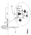
- a drilling engineer collects drilling fluid from a wellbore 100 during the drilling of a well.
- the collection process may include diverting a return flow 101 of drilling fluid from wellbore 100 to a fluid monitoring system 102 prior to processing of the drilling fluid being processed by cleaning equipment 103 (e.g ., vibratory shakers, degassers, centrifuges, hydrocyclones, etc.).
- cleaning equipment 103 e.g ., vibratory shakers, degassers, centrifuges, hydrocyclones, etc.
- the fluid flows through return line 101.
- the drilling engineer may actuate an inlet valve 104 in fluid communication with an inlet 105 of return line 101. Tests on the fluid may then be performed by fluid monitoring system 102, as will be described in detail below. After the tests are completed, an outlet valve 107 may be opened, and the fluid may then be pumped through an outlet 113 of return line 101.
- tested fluid may then re-enter return line 101 and be pumped to downstream cleaning equipment 103.
- tested fluids may be discharged from fluid monitoring system 102 via a discharge line 108 and into a discharge tank 109.
- Such a discharge process may be beneficial in a fluid monitoring system 102 that includes the use of chemicals that may damage the fluid, cleaning equipment 103, or other aspects of the drilling operations.
- the fluids may be reintroduced into an active fluid system of the drilling operation or cleaning and reuse.
- fluid monitoring system 102 may be configured to receive a flow of cuttings slurry prior to injection into wellbore 100.
- fluid monitoring system 102 would receive a flow of cuttings slurry from a cuttings re-injection system (not shown) instead of from return line 101, such that properties of the slurry could be monitored and adjusted prior to injection into wellbore 100.
- a cuttings re-injection system not shown
- fluid returns from a wellbore through return line 201.
- the fluid is allowed to circulate through the active drilling system, thereby bypassing fluid test apparatus.
- inlet valve 204 may be opened, such that a flow of fluid enters the fluid monitoring system through an inlet 205.
- a pump 211 is actuated, and a control valve 212 is opened to allow a flow of fluid from inlet 205 to viscometer 210.
- pump 211 is a pneumatic pump, however, those of ordinary skill in the art will appreciate that in alternate embodiments, pump 211 may be any type of pump capable of providing a flow of fluid through a test apparatus. In other embodiments, pump 211 may include, for example, any type of positive displacement pump, centrifugal pump, diaphragm pump, or kinetic pump.
- pump 211 may not be necessary to supply a flow of fluid to viscometer 210. In such an embodiment if the pressure in the return line is sufficient to drive the fluid into viscometer, pump 211 may either be excluded from the system, or otherwise not used.
- a pressure gauge 218 is disposed between fluid inlet 205 and pump 211. Pressure gauge 218 allows a drilling operator to monitor pressure in the fluid line to determine if the fluid pressure is within operational limits. As such, pressure gauge 218 may allow the fluid monitoring system or the operator to stop the flow of fluid should a pressure fall outside of the operational limits, thereby protecting the system from adverse well conditions.
- pump 211 When a drilling engineer begins a fluid test, pump 211 is actuated and a predetermined volume of fluid is pumped into viscometer 210. When the predetermined volume of fluid for the test is in viscometer 210, control valve 212 is closed and an outlet valve 207 is opened to allow residual fluid to exit the fluid monitoring system. As residual fluid is removed from the fluid monitoring system, inlet valve 204 may be closed such that no additional fluid enters the fluid monitoring systems. In certain embodiments, it may be beneficial to allow both inlet valve 204 and outlet valve 207 to remain open, thereby allowing a flow of drilling fluid through the fluid monitoring system.
- inlet valve 204 is closed, such that the return flow of drilling fluid remains in return line 201.
- the pressure in the system is not affected by the pressure of the return flow of drilling fluid in return line 201.
- pump 211 is actuated to remove the fluid from viscometer 210.
- outlet valve 207 is opened to allow the fluid to be pumped back through an outlet 213 into return line 201 and back into the active system.
- fluid may be removed from viscometer 210 and discarded, such that tested fluid does not re-enter the active system.
- Such an embodiment may be beneficial if chemicals are used in the testing, or if conditions of the test alter the fluid so that it could damage components of the active fluid system.
- the drilling engineer may begin a cleaning operation.
- cleaning fluid is pumped from a cleaning fluid tank 214 via pump 211 through open control valve 212 and into viscometer 210.
- the cleaning fluid may include water, base oil, surfactants, and other substances that may remove residual drilling fluid from internal components of viscometer 210.
- Cleaning fluid tank 214 may also include components to monitor, for example, cleaning fluid levels, pressure within the cleaning fluid tank 214, and flow rates of cleaning fluid out of cleaning fluid tank 214.
- one or more valves may be disposed between cleaning fluid tank 214 and pump 211 to further control the flow of cleaning fluid therethrough.
- viscometer 210 may be actuated such that a bob (not shown) or a sleeve (not shown) of the viscometer is rotated, thereby stirring the cleaning fluid in viscometer 210.
- the movement inside viscometer 210 along with the cleaning fluid may dissolve solid particles and substances that may become adhered to the internal components of viscometer 210 during the test.
- cleaning operations, and movement of internal components of viscometer 210 may last for several minutes ( e.g ., 5 minutes) or until the internal components of viscometer 210 are substantially clean.
- the cleaning fluid may be drained from viscometer 210 via opening a discharge valve 215 providing fluid communication between viscometer 210 and a discharge tank 216.
- providing a flow of used cleaning fluid to discharge tank 216 may thereby prevent cleaning fluids from entering the active fluid system.
- the cleaning fluid may be discharged into the active fluid system if the cleaning fluid being used is benign with respect to components of the drilling system, or with respect to the fluids being used in the drilling operation.
- cleaning fluid may be recycled back into cleaning fluid tanks 214 for reuse in further cleaning operations.
- Such an embodiment may be useful when the fluid being tested does not readily adhere to the internal components of viscometer 210, or when the fluid may be separated from cleaning fluid in cleaning fluid tanks 214.
- skimmers (not shown) or other removal apparatus, such as level valves (not shown) may also be used to provide for active removal or siphoning of separated fluids from cleaning fluid tanks 214.
- level sensors (not shown) may further provide for monitoring of fluid levels within the tank.
- inlet valve 204 may be opened, and fluid from return line 201 may be pumped via pump 211 through open valve 212 and into viscometer 210.
- the testing and cleaning cycles may be repeated so that monitoring of fluids in the active fluid system may be automatically monitored.
- the automated control of the fluid tests and cleaning operations may occur without drilling operator input.
- a drilling engineer may request either a test or a cleaning operation be run.
- embodiments of the present disclosure provide for a manual override to the system, thereby giving the drilling engineer control over the fluid monitoring system. Such demand based test and cleaning cycles are discussed in detail below.
- System controller 217 may include a programmable logic controller ("PLC"), a personal computer, or other means of providing instructions to the fluid monitoring system as would be known to those of ordinary skill in the art.
- PLC programmable logic controller
- system controller 217 is functionally connected to inlet, control, discharge, and outlet valves 204, 207, 215, and 212 rspectfully, viscometer 210, cleaning fluid tanks 214, and pump 211, as is illustrated by the dashed lines of Figure 2 .
- Functional control may include direct connections, such as wiring, or remote connection, such as may be provided by intranet or internet protocols transmitted wirelessly.
- System controller 217 is generally configured to provide instructions to components of fluid monitoring system for controlling the transfer of fluids throughout the system, as well as monitoring and outputting results of the fluid tests and cleaning operations. For example, system controller 217 provides instructions for actuating pump 211 and components of cleaning fluid tank 214 to provide a flow of cleaning fluid between cleaning fluid tank 214 and viscometer 210. Additionally, system controller 217 provides instructions for monitoring viscometer 210, the pressures within the fluid monitoring system via pressure gauge 218, and the output of test results from viscometer 210. In certain embodiments, system controller 217 may include a network of system controllers, such that multiple PLCs are employed to control different aspects of the fluid monitoring system.
- a first PLC may be configured to monitor the test
- a second PLC may be configured to monitor the cleaning operation
- a third PLC may be configured to transmit results of the test to an output device (e.g ., a monitor, a printer, or a network).
- an output device e.g ., a monitor, a printer, or a network.
- both PLCs and computer systems may be used for different aspects of the operation.
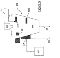
- viscometer 310 includes a heating cup 319 and a viscometer head 320.
- Heating cup 219 is a low volume vessel configured to receive a flow of fluids from the active drilling system, as described above. The flow of fluids may be pumped into heating cup 319 via a heating cup inlet 322, which provides fluid communication between heating cup 219 and a pump (not shown).
- heating cup inlet 322 provides fluid communication between heating cup 319 and a cleaning fluid tank (not shown) and other components of the fluid monitoring system.
- heating cup 319 may include a vessel capable of receiving 500 ml of fluid; however, in alternate embodiments, different volume heating cups 319 may be used according to the requirements of the specific tests being performed.
- a plurality of fluid level sensors 323 may be disposed in or around heating cup 319.
- a base fluid level sensor 323a may provide a base level, otherwise recognized as the minimum volume of fluid required to perform a test.
- a secondary level sensor 323b may provide a second level indicating a maximum allowable fluid level in heating cup 319 for a test to be performed.
- secondary level sensor 323b may also serve as a redundant overflow sensor, thereby informing a drilling engineer or a system controller when an overflow condition exists.
- level sensors 323 may provide information to the system controller to indicate a level of cleaning fluid within heating cup 319.
- one or more temperature controllers 324 may be functionally disposed in or on heating cup 319. Temperature controllers 324 may provide data to system controller indicating the temperature of heating cup 319, fluids within heating cup 319, or of other components of the fluid monitoring system.
- a heating element 325 is disposed around heating cup 319. Heating element 325 provides a source of heat to heating cup, such that the temperature of fluids within heating cup 319 may be increase to optimal test levels.
- temperatures used during fluid testing may range between 25°C and 50°C; however, in certain embodiments, depending on the specific tests being performed, heating element 325 may preferably be capable of heating the fluids to approximately 80°C.
- fluids may be tested at temperatures of less than 25°C or greater than 80°C.
- cooling jacket 326 may be disposed around heating cup 319.
- cooling jack 326 is in fluid communication with a cold-water tank 327, such that cold water may be pumped into cooling jacket 326 to speed the cooling of heating cup 319 and the fluids contained therein.
- the water may be discarded to a waste water drain 328.
- the cold water may be recycled from cooling jacket 326 back into cold-water tank 327.
- discharge port 329 is located at the bottom of heating cup 319 such that gravity may primarily provide for the removal of the fluids.
- discharge port 329 may be located at a different location on heating cup 319, and additional components may be used to facilitate the removal of fluids from heating cup 319. Additional components may include pumps, siphoning devices, or vacuums, and may further eliminate residual fluids in heating cup 319.
- the fluid monitoring system also includes a viscometer head 320 configured for use with heating cup 319.
- viscometer head 320 includes a bob 330 configured to rotate within heating cup 319 such that fluid properties may be determined.
- other types of viscometers known in the art including, for example, viscometers having rotable sleeves, may be used according to embodiments disclosed herein.
- Viscometer 310 including viscometer head 310 and the components of viscometer 310 and heating cup 319 discussed above, may be controlled via a system controller. The system controller is functionally connected to viscometer 310, as illustrated by dashed line at 331.
- additional components may be included in alternate configurations of the present disclosure.
- additional components may include, for example, temperature probes, temperature sensors, viscometer temperature probes, pH monitors, redundant overflow sensors, additional valves, pressure sensors, check valves, isolation valves, or other components as may be required to provide optimal fluid testing and equipment cleaning operations.
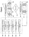
- a fluid is introduced (400) into a fluid analyzer.
- the fluid analyzer may include a viscometer or other device capable of determining, for example, fluid viscosity and rheological properties.
- Introduction (400) of the fluid may also include the methods described above.
- a specific volume of fluid for example, 300ml may be introduced (400) by pumping the fluid from a return line at a drilling location into the fluid analyzer.
- the analyzing (401) may include rotating (402) a bob or sleeve of fluid analyzer with respect to a heating cup of the fluid analyzer, such that a torque required to rotate the bob through the fluid at a specified rotational speed is determined (403).
- the determined (403) torque may then be used to calculate a viscosity and the rheological properties of the fluid.
- the determined (403) viscosity and/or rheological properties of the fluid may then be output for further processing or storing as will be described in detail below.
- the fluid Upon completion of the fluid test, the fluid is removed (404) from the fluid analyzer, and a cleaning fluid is introduced (405) into the heating cup.
- a specified volume of fluid may be introduced (405), such that upon actuation of the viscometer during a cleaning operation, the fluid contacts at least the bob and internal walls of the heating cup to facilitate the removal of residual fluids therefrom.
- the volume of cleaning fluid introduced (405) into heating cup may vary according to the properties of the fluid being tested, but generally should be at least a similar volume as used during the initial fluid test.
- a cleaning operation is executed (406).
- the cleaning operation includes actuating (407) the fluid analyzer such that the bob or sleeve of the fluid analyzer is rotated (408) with respect to the heating cup.
- the rotation (408) of the relative component parts of the fluid analyzer will cause the cleaning fluid to be stirred (409), such that the cleaning fluid contacts the bob and/or sleeve, as well as the internal walls of the heating cup.
- the rotational speed used will vary according to the properties of the tested fluid; however, in certain embodiments, the bob/sleeve should be rotated for at least 5 minutes at 300 rotations per minute. In certain embodiments, if a particularly thick or solid laden fluid is being tested, a longer cleaning operation may be required to properly clean the components of the fluid analyzer. Likewise, if particularly thin fluids are being tested, shorter cleaning operations may be used.
- the cleaning fluid is drained (410) from the heating cup, and the fluid analyzer is in condition for another test cycle.
- multiple cleaning operations may be used to further clean components of the fluid analyzer.
- a system controller may determine, based on readings from fluid analyzer sensors, that residual fluid or solids remain in the heating cup or on the bob/sleeve after the cleaning operation. The system controller may then delay a test cycle, and instead run a second cleaning operation. Alternatively, the system controller may run the test cycle, but inform a drilling engineer that the fluid analyzer is not operating in optimal condition.
- the fluid analyzer may stop the test cycle from running and inform the drilling engineer that the fluid analyzer needs to be inspected.
- the system controller may therein verify the operating condition of the fluid analyzer and components of the fluid monitoring system so as to ensure optimal operating conditions are maintained.
- the drilling engineer may not be required to constantly monitor the fluid analyzer.
- the system controller may provide instructions to the fluid analyzer and components of the fluid monitoring system to automate both the test cycle and the cleaning operation. Because the system controller does not require a drilling engineer to manually adjust the fluid analyzer ( e.g ., add fluids or cleaning the components) between tests, the fluid monitoring system may function without substantial human input.
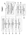
- FIG. 5 a flowchart of a system for monitoring fluids in accordance with an embodiment of the present disclosure is shown.
- the process as described in Figure 4 with respect to steps 400 through 410 is substantially similar to the steps 500, 501, 504, 505, 506, and 510 of Figure 5 .
- a fluid is introduced (500) into a fluid analyzer, analyzed (501) with the fluid analyzer, and removed (504) from the fluid analyzer.
- a cleaning fluid is introduced (505) into a heating cup, a cleaning operation is executed (506), and the cleaning fluid is drained (510) from the heating cup.
- the above-described steps describe the primary function of the fluid analyzer during the testing and cleaning operations.
- additional functions may be performed by the fluid monitoring system contemporaneous to the above described steps.
- the results of the test are output (511) from the fluid analyzer to one or more of a drilling management system (512), a visual display device (513) and/or an offsite monitoring system (514).
- the output (511) function may include transferring test data from the fluid analyzer to a system controller for additional analysis, or alternatively, the fluid analyzer may analyze the data, and only the results of the test may be transferred to the system controller.
- the test data or results may be directly sent to the drilling management system (512), the visual display device (513), or the offsite monitoring system (514).
- the drilling management system (512) may include programs or systems used on drilling rigs for monitoring and controlling drilling parameters.
- Drilling parameters that may be monitored and/or controlled by the drilling management system (512) include drilling fluid flow rate, torque on bit, rotational speed of a drill bit, and other properties as would be known to those of ordinary skill in the art.
- fluid properties such as viscosity and rheology
- the drilling management system (512) or engineers in control thereof may be able to adjust drilling parameters to compensate for drilling fluid parameters.
- the system controller of the present application may use data from the drilling management system (512) to adjust drilling fluid parameters in view of the drilling parameters used by the drilling management system (512).
- Results output (511) to a visual display device may include outputting (511) test data and/or results data to a monitor, or other device capable of displaying the data. Additionally, the data may be displayed as both graphical and numerical representations including, for example, graphs of fluid viscosity, data-tables of viscosities, and cumulative data collected over time.
- the visual display device may also include input functionality, such as input peripherals or a touch screen, such that a drilling engineer may adjust parameters of the test or cleaning operation directly from the display device.
- Offsite monitoring system (514) may include labs and monitoring facilities located away from the drilling location.
- An exemplary lab may include a fluid analysis lab, wherein a drilling engineer may use information output (511) by the fluid analyzer to determine adjustments for fluid parameters (e.g ., viscosity, density, and composition).
- offsite monitory systems (514) in communication with embodiments of the present disclosure by, for example, networks, may provide for the transfer of drilling fluid information between onsite and offsite locations.
- the test and cleaning cycles of the present system may be executed according to varied sequencing.
- a drilling engineer may indicate that the fluid monitoring system should automatically perform intermittent tests.
- the drilling engineer may program the system controller of the fluid monitoring system to perform a fluid analysis according to a time profile (e.g ., every 5, 10, or 15 minutes).
- a drilling engineer may interrupt an automated sequence with specific instructions to perform a test.
- a drilling engineer may program the fluid monitoring system with cleaning operation execution instructions to perform one or more cleaning operations between test cycles.
- demand cycle (515) includes a drilling operator interrupting (516) the automated testing sequence.
- interrupting (516) the automated testing includes actuation (517) of a demand analyzing operation or actuation (518) of a demand cleaning operation.
- a demand analyzing operation includes running a test with the fluid analyzer and the processes necessary to complete such test.
- a demand cleaning operation includes introducing a cleaning fluid into the fluid analyzer, executing a cleaning operation, and any additional steps necessary to clean the fluid analyzer.
- both testing and cleaning cycles may be automated.
- a system controller may provide automation controls for the fluid analyzer for controlling the automated fluid monitoring system.
- These instructions include directions to both test a fluid and clean the fluid analyzer after the tests.
- instructions for controlling the operation of the fluid monitoring system may be downloaded to the fluid analyzer from an offsite location. Such instructions may include protocols for a demand analysis or demand cleaning operation.
- the fluid monitoring system may include cameras for direct monitoring of the analysis and/or testing.
- Exemplary cameras may include digital still cameras, digital video cameras, closed-circuit cameras, or other types of cameras known to those of ordinary skill in the art.
- such cameras may be configured to interface directly with a system controller of the fluid monitoring system, such that a drilling engineer at an offsite location may control aspects of the analysis and cleaning operations remotely.
- a system controller of the fluid monitoring system such that a drilling engineer at an offsite location may control aspects of the analysis and cleaning operations remotely.
- Those of ordinary skill in the art will appreciate that embodiments that do not include a camera system may also be remotely controlled from an offsite location by providing instructions to the system controller in response to, for example, specific output results provided by the fluid monitoring system.
- embodiments of the present disclosure for the monitoring of drilling fluid rheology at a drilling location. Because a drilling engineer does not have to manually test the drilling fluid, a time consuming and potentially dangerous process, the drilling fluid properties may be tested more frequently. More frequent drilling fluid tests may allow for intermittent alterations to the drilling fluid to optimize the fluid for the specific conditions of the wellbore being drilled. Additionally, the automated process of monitoring fluid rheology may provide drilling engineers with a substantially continuous update of the condition of the fluid in the wellbore. Such continuous monitoring may allow for quicker adjustments to the drilling fluid and/or drilling parameters, such that drilling may be more efficient.
- embodiments of the present disclosure may be used with multiple types of fluids used at drilling locations.
- completion fluids may be monitored during well completion operations. By measuring fluid properties of completion fluids, damage to the wellbore and completion tools, such as production liners, packers, downhole valves, and shooting perforators may be avoided. Additionally, a determination of completion fluid viscosity during a completion operation may inform a drilling operator when solids content in a near-wellbore area has reached levels that may interfere with either the well completion or later production operations.
- Embodiments of the present disclosure may also be advantageously used in the re-injection of cuttings into a wellbore.
- the fluid properties of a re-injection slurry may be monitored prior to injection to ensure a proper slurry viscosity. Because the viscosity may be monitored with greater frequency during cuttings re-injection, a proper concentration of solids content within the slurry may be determined. By determining a proper solids content for the specific re-injection, problems associated with slurries having too great a solids content, such as the accidental release of injected slurry into the environment, excessive erosion wear from injection, and well plugging in the instance of improper slurry rheology, may be avoided.
- the slurry monitoring processes disclosed herein may decrease the risks associated with a less expensive process for disposing drilling waste.
- embodiments disclosed herein provide a self-cleaning system for monitoring of fluid rheology at a drilling location. Because embodiments of the present disclosure are self-cleaning during normal operations, the fluid monitor may continue to provide accurate test results after multiple tests. Moreover, embodiments disclosed herein may provide for the remote control of the monitoring operations, such that a drilling engineer located offsite may be able to control and receive data from the fluid monitor. Remote access to control of the fluid monitor may further allow drilling engineers to monitor fluids, order a fluid test at a specific time, and monitor operating conditions of the fluid monitor. Remote access, control, and command over test and cleaning operations may thereby result in the substantially continuous monitoring of fluids at a drilling location. Such monitoring practices may thereby allow for adjustments to fluid parameter and more efficient fluid operation within the wellbore.
Landscapes
- Life Sciences & Earth Sciences (AREA)
- Engineering & Computer Science (AREA)
- Chemical & Material Sciences (AREA)
- Health & Medical Sciences (AREA)
- Physics & Mathematics (AREA)
- Geology (AREA)
- Mining & Mineral Resources (AREA)
- Oil, Petroleum & Natural Gas (AREA)
- Analytical Chemistry (AREA)
- General Life Sciences & Earth Sciences (AREA)
- Chemical Kinetics & Catalysis (AREA)
- General Chemical & Material Sciences (AREA)
- Fluid Mechanics (AREA)
- Environmental & Geological Engineering (AREA)
- Food Science & Technology (AREA)
- Medicinal Chemistry (AREA)
- Geochemistry & Mineralogy (AREA)
- Biochemistry (AREA)
- General Health & Medical Sciences (AREA)
- General Physics & Mathematics (AREA)
- Immunology (AREA)
- Pathology (AREA)
- Cleaning By Liquid Or Steam (AREA)
- Earth Drilling (AREA)
- Sampling And Sample Adjustment (AREA)
- Cleaning In General (AREA)
- Automatic Analysis And Handling Materials Therefor (AREA)
Claims (15)
- System (102) zur Überwachung von Flüssigkeiten an einer Bohrstelle, dadurch gekennzeichnet, dass es Folgendes umfasst:ein Viskosimeter (210, 310) mit einem Heizbecher (319),eine Pumpe (211) in Strömungsverbindung mit dem Heizbecher (319), wobei die Pumpe (211) so ausgelegt ist, dass sie einen Flüssigkeitsstrom von einem Einlass einer Flüssigkeitsleitung zu dem Heizbecher (319) liefert,einen Behälter (214) für Reinigungsflüssigkeit in Strömungsverbindung mit dem Heizbecher (319), wobei die Pumpe (211) so ausgelegt ist, dass sie einen Strom von Reinigungsflüssigkeit von dem Behälter (214) für Reinigungsflüssigkeit zu dem Heizbecher (319) liefert, undeinen Systemregler (217), der so ausgelegt ist, dass er Anweisungen an die Pumpe (211) liefert, um den Strom von Reinigungsflüssigkeit von dem Behälter (214) für Reinigungsflüssigkeit zu dem Heizbecher (319) zu regeln.
- System (102) nach Anspruch 1, ferner umfassend:ein Heizelement (325), das benachbart zu dem Heizbecher (319) angeordnet ist, undeinen Temperaturregler (324), der mit dem Heizelement (325) elektrisch verbunden und so ausgelegt ist, dass er eine Temperatur des Heizbechers (319) regelt.
- System (102) nach Anspruch 2, ferner umfassend:einen Wasserbehälter (327) undeinen Kühlmantel (326), der benachbart zu dem Heizbecher (319) angeordnet ist und in Strömungsverbindung mit dem Wasserbehälter (327) steht.
- System (102) nach Anspruch 1, wobei der Systemregler (217) Anweisungen umfasst, um das Viskosimeter (210, 310) so zu regeln, dass es einen Rheologietest durchführt.
- System (102) nach Anspruch 1, wobei der Systemregler (217) Anweisungen für das System (102) umfasst, damit dieses einen automatisierten Reinigungsvorgang durchführt.
- System (102) nach Anspruch 1, ferner umfassend:eine Ablassöffnung (329) in Strömungsverbindung mit dem Heizbecher (319) undeinen Ablassbehälter (109, 216) in Strömungsverbindung mit der Ablassöffnung (329).
- System (102) nach Anspruch 1, ferner umfassend:eine rückführende Leitung (101, 201) in Strömungsverbindung mit einem Einlass (105, 205) an der rückführenden Leitung und einem Auslass (113, 213) an der rückführenden Leitung,wobei die rückführende Leitung (101, 201) so ausgelegt ist, dass sie die Bohrspülung an einer Bohrstelle zirkulieren lässt.
- System (102) nach Anspruch 1, wobei die Flüssigkeit wenigstens eines aus einer Gruppe umfasst, welche aus einer Bohrspülung, einem Schlamm zur Wiedereinbringung von Bohrklein und einer Komplettierungsflüssigkeit besteht.
- System (102) nach Anspruch 1, wobei der Systemregler (217) Anweisungen an das System (102) zur Automatisierung sowohl der Test- als auch der Reinigungszyklen liefert.
- Verfahren zur automatischen Überwachung von Flüssigkeiten an einer Bohrstelle, wobei das Verfahren Folgendes umfasst:Bereitstellen von Automatisierungssteuerungen für einen Flüssigkeitsanalysator, um die automatische Überwachung von Flüssigkeiten zu regeln, wobei die Steuerungen Anweisungen für folgende Schritte umfassen:Einleiten (400, 500) einer Flüssigkeit in einen Flüssigkeitsanalysator, wobei der Flüssigkeitsanalysator ein Viskosimeter (210, 310) mit einem Heizbecher (319) umfasst,Analysieren (401, 501) der Flüssigkeit mit dem Flüssigkeitsanalysator, wobei das Analysieren das Bestimmen von Flüssigkeitseigenschaften umfasst,Entnehmen (404, 504) der Flüssigkeit aus dem Flüssigkeitsanalysator,Einleiten (405, 505) einer Reinigungsflüssigkeit in den Heizbecher (319),Durchführen (406, 506) eines Reinigungslaufs undAblassen (410, 510) der Reinigungsflüssigkeit aus dem Heizbecher (319).
- Verfahren nach Anspruch 10, wobei der Reinigungslauf Folgendes umfasst:Betätigen (407) des Viskosimeters (210, 310), wobei das Betätigen Folgendes umfasst:Drehen (408) einer Platte des Viskosimeters (210, 310) undRühren (409) der Reinigungsflüssigkeit in dem Heizbecher (319) .
- Verfahren nach Anspruch 10, wobei das Analysieren Folgendes umfasst:Drehen (402) einer Platte in dem Heizbecher (319) mit einem bekannten Flüssigkeitsvolumen undBestimmen (403) eines Drehmoments, das für das Drehen der Platte in der Flüssigkeit bei einer vorgegebenen Drehgeschwindigkeit erforderlich ist.
- Verfahren nach Anspruch 10, ferner umfassend:Ausgeben der Ergebnisse des Analysierens, wobei die Ergebnisse wenigstens an ein Bohrmanagementsystem (512),ein optisches Anzeigegerät (513) und/oder eine Fernüberwachungsstation (514) ausgegeben werden.
- Verfahren nach Anspruch 10, wobei die Automatisierungssteuerungen ferner Anweisungen für einen Bedarfszyklus (515) umfassen, wobei der Bedarfszyklus Folgendes umfasst:Unterbrechen (516) des Automatisierungszyklus undIngangsetzen eines Bedarfsanalyselaufs (517) und/ oder eines Bedarfsreinigungslaufs (518).
- Verfahren nach Anspruch 10, wobei die Flüssigkeit wenigstens eines aus einer Gruppe umfasst, welche aus einer Bohrspülung, einem Schlamm zur Wiedereinbringung von Bohrklein und einer Komplettierungsflüssigkeit besteht.
Applications Claiming Priority (2)
| Application Number | Priority Date | Filing Date | Title |
|---|---|---|---|
| US98280507P | 2007-10-26 | 2007-10-26 | |
| PCT/US2008/081114 WO2009055672A1 (en) | 2007-10-26 | 2008-10-24 | System and method of analyzing fluids at a drilling location |
Publications (2)
| Publication Number | Publication Date |
|---|---|
| EP2220487A1 EP2220487A1 (de) | 2010-08-25 |
| EP2220487B1 true EP2220487B1 (de) | 2011-06-22 |
Family
ID=40347989
Family Applications (1)
| Application Number | Title | Priority Date | Filing Date |
|---|---|---|---|
| EP08841537A Active EP2220487B1 (de) | 2007-10-26 | 2008-10-24 | System und verfahren zur analyse von fluiden an einer bohrstelle |
Country Status (9)
| Country | Link |
|---|---|
| US (1) | US8392121B2 (de) |
| EP (1) | EP2220487B1 (de) |
| AT (1) | ATE514079T1 (de) |
| BR (1) | BRPI0819208A8 (de) |
| CA (1) | CA2703741C (de) |
| DK (1) | DK2220487T3 (de) |
| EA (1) | EA018141B1 (de) |
| MX (1) | MX2010004462A (de) |
| WO (1) | WO2009055672A1 (de) |
Families Citing this family (30)
| Publication number | Priority date | Publication date | Assignee | Title |
|---|---|---|---|---|
| EA201790264A1 (ru) | 2009-10-09 | 2017-10-31 | Эм-Ай Эл.Эл.Си. | Измерение реологии жидкости с применением приспособления с воронкой |
| FR2955607A1 (fr) * | 2010-01-27 | 2011-07-29 | Geoservices Equipements | Ensemble de mesure en ligne des proprietes rheologiques d'un fluide de forage et procede de mesure associe. |
| AU2011215835A1 (en) * | 2010-02-10 | 2012-08-30 | Schlumberger Norge As | Automated drilling fluid analyzer |
| US9222350B2 (en) | 2011-06-21 | 2015-12-29 | Diamond Innovations, Inc. | Cutter tool insert having sensing device |
| US8881577B1 (en) | 2012-04-02 | 2014-11-11 | Agar Corporation, Ltd. | Method and system for analysis of rheological properties and composition of multi-component fluids |
| US20130269933A1 (en) * | 2012-04-13 | 2013-10-17 | Schlumberger Technology Corporation | Method and apparatus to prepare drill cuttings for petrophysical analysis by infrared spectroscopy and gas sorption |
| US9567852B2 (en) | 2012-12-13 | 2017-02-14 | Halliburton Energy Services, Inc. | Systems and methods for measuring fluid additive concentrations for real time drilling fluid management |
| US8575541B1 (en) * | 2012-12-13 | 2013-11-05 | Halliburton Energy Services, Inc. | Systems and methods for real time monitoring and management of wellbore servicing fluids |
| KR102239828B1 (ko) * | 2014-03-07 | 2021-04-13 | 대우조선해양 주식회사 | 시추선의 머드 탱크 |
| KR102239829B1 (ko) * | 2014-03-14 | 2021-04-13 | 대우조선해양 주식회사 | 기액 분리기 테스트 장치 및 방법 |
| MX2017003511A (es) | 2014-09-16 | 2017-06-21 | Halliburton Energy Services Inc | Sensor de viscosimetro para fluido de formacion en el interior del pozo. |
| WO2017059871A2 (en) * | 2015-10-04 | 2017-04-13 | Abd Elshafy Mahmoud Khaled Sayed | Automated mud testing kit (amtk) |
| US10954783B2 (en) * | 2015-10-22 | 2021-03-23 | Halliburton Energy Services, Inc. | Extraction cleaner and gas system check |
| US10983499B2 (en) * | 2016-04-20 | 2021-04-20 | Baker Hughes, A Ge Company, Llc | Drilling fluid pH monitoring and control |
| US10151674B2 (en) * | 2017-01-19 | 2018-12-11 | Schlumberger Technology Corporation | Oil-based mud drill cutting cleaning for infrared spectroscopy |
| CN107219339B (zh) * | 2017-07-28 | 2023-10-31 | 中石化石油工程技术服务有限公司 | 钻井液现场分析化验操作台 |
| WO2019046904A1 (en) * | 2017-09-08 | 2019-03-14 | Australian Mud Company Pty Ltd | SYSTEM AND METHOD FOR DRILLING MUD MANAGEMENT |
| US20190356696A1 (en) * | 2018-05-21 | 2019-11-21 | Schlumberger Technology Corporation | System and method for cybersecurity framework among network devices |
| US10845285B1 (en) | 2018-08-31 | 2020-11-24 | Hongfeng Bi | Fast response fluid properties monitoring system |
| CN111044400B (zh) * | 2019-12-27 | 2021-01-19 | 浙江大学 | 高灰低温烟气下中间介质管式换热器加速冲蚀磨损试验装置 |
| US11435274B2 (en) | 2020-06-04 | 2022-09-06 | Saudi Arabian Oil Company | Continuous mud rheology monitoring |
| US11536136B2 (en) | 2020-08-28 | 2022-12-27 | Halliburton Energy Services, Inc. | Plasma chemistry based analysis and operations for pulse power drilling |
| US11499421B2 (en) | 2020-08-28 | 2022-11-15 | Halliburton Energy Services, Inc. | Plasma chemistry based analysis and operations for pulse power drilling |
| US11585743B2 (en) | 2020-08-28 | 2023-02-21 | Halliburton Energy Services, Inc. | Determining formation porosity and permeability |
| US12188353B2 (en) | 2020-08-28 | 2025-01-07 | Halliburton Energy Services, Inc. | Plasma chemistry derived relation between arc and spark for pulse power drilling |
| US11459883B2 (en) | 2020-08-28 | 2022-10-04 | Halliburton Energy Services, Inc. | Plasma chemistry derived formation rock evaluation for pulse power drilling |
| US11619129B2 (en) | 2020-08-28 | 2023-04-04 | Halliburton Energy Services, Inc. | Estimating formation isotopic concentration with pulsed power drilling |
| EP4359634A4 (de) * | 2021-06-22 | 2025-03-19 | Services Pétroliers Schlumberger | Verfahren und vorrichtung zur entfernung von rückständen während bohrlochoperationen |
| US11892421B2 (en) | 2021-12-06 | 2024-02-06 | Schlumberger Technology Corporation | System and method for cleaning electrical stability probe |
| US12222268B1 (en) * | 2023-07-20 | 2025-02-11 | Weatherford Technology Holdings, Llc | Non-intrusive rheometer for use in well operations |
Family Cites Families (9)
| Publication number | Priority date | Publication date | Assignee | Title |
|---|---|---|---|---|
| US3286510A (en) * | 1964-05-18 | 1966-11-22 | Phillips Petroleum Co | Drilling mud test apparatus and process |
| EP0211112A1 (de) * | 1985-07-26 | 1987-02-25 | Hutchison-Hayes International, Inc. | Verfahren und Gerät zur Echtzeitmessung der Eigenschaften von Bohrflüssigkeiten |
| US4557142A (en) * | 1983-10-13 | 1985-12-10 | Hutchinson-Hayes International, Inc. | Apparatus and method for real-time measurement of drilling fluid properties |
| GB2377952B (en) | 2001-07-27 | 2004-01-28 | Schlumberger Holdings | Receptacle for sampling downhole |
| US7736521B2 (en) * | 2004-03-15 | 2010-06-15 | Total Separation Solutions, Llc | Viscosity control and filtration of well fluids |
| US7521400B2 (en) * | 2004-04-16 | 2009-04-21 | Schlumberger Technology Corporation | Gelled oil with surfactant |
| GB2431673B (en) * | 2005-10-26 | 2008-03-12 | Schlumberger Holdings | Downhole sampling apparatus and method for using same |
| US7677307B2 (en) * | 2006-10-18 | 2010-03-16 | Schlumberger Technology Corporation | Apparatus and methods to remove impurities at a sensor in a downhole tool |
| US7644610B2 (en) * | 2007-08-24 | 2010-01-12 | Baker Hughes Incorporated | Automated formation fluid clean-up to sampling switchover |
-
2008
- 2008-10-24 DK DK08841537.7T patent/DK2220487T3/da active
- 2008-10-24 BR BRPI0819208A patent/BRPI0819208A8/pt not_active Application Discontinuation
- 2008-10-24 MX MX2010004462A patent/MX2010004462A/es active IP Right Grant
- 2008-10-24 CA CA2703741A patent/CA2703741C/en active Active
- 2008-10-24 EA EA201070530A patent/EA018141B1/ru not_active IP Right Cessation
- 2008-10-24 US US12/739,578 patent/US8392121B2/en active Active
- 2008-10-24 WO PCT/US2008/081114 patent/WO2009055672A1/en not_active Ceased
- 2008-10-24 EP EP08841537A patent/EP2220487B1/de active Active
- 2008-10-24 AT AT08841537T patent/ATE514079T1/de not_active IP Right Cessation
Also Published As
| Publication number | Publication date |
|---|---|
| WO2009055672A1 (en) | 2009-04-30 |
| MX2010004462A (es) | 2010-08-04 |
| EA018141B1 (ru) | 2013-05-30 |
| CA2703741A1 (en) | 2009-04-30 |
| US20100250142A1 (en) | 2010-09-30 |
| US8392121B2 (en) | 2013-03-05 |
| ATE514079T1 (de) | 2011-07-15 |
| EA201070530A1 (ru) | 2010-12-30 |
| DK2220487T3 (da) | 2011-10-17 |
| CA2703741C (en) | 2013-06-25 |
| BRPI0819208A2 (pt) | 2015-05-05 |
| BRPI0819208A8 (pt) | 2016-01-12 |
| EP2220487A1 (de) | 2010-08-25 |
Similar Documents
| Publication | Publication Date | Title |
|---|---|---|
| EP2220487B1 (de) | System und verfahren zur analyse von fluiden an einer bohrstelle | |
| RU2301319C2 (ru) | Устройство и способ динамического регулирования давления в кольцевом пространстве | |
| RU2484242C2 (ru) | Система и способ контроля и регулирования дебита скважин | |
| US7721595B2 (en) | Apparatus and method to monitor slurries for waste re-injection | |
| CN112219009B (zh) | 用于选择井筒钻井流体堵漏材料的智能系统 | |
| WO2014159902A2 (en) | Closed loop drilling fluids circulation and management system | |
| NO343297B1 (no) | Apparat og fremgangsmåte for styring av viskositeten av et borefluid | |
| EA028646B1 (ru) | Система, способ и устройство для анализа бурового раствора | |
| NO20171488A1 (en) | Optimized recycling of drilling fluids by coordinating operation of separation units | |
| CA2852909A1 (en) | Parameter measuring apparatus for a centrifuge | |
| EP3583293A1 (de) | Intelligentes selektives bohrfluidsystem | |
| US11255191B2 (en) | Methods to characterize wellbore fluid composition and provide optimal additive dosing using MEMS technology | |
| US10378295B2 (en) | Bypass flushing for gas extraction systems | |
| WO2017116485A1 (en) | Managed pressure system for pressure testing in well bore operations | |
| WO2015005998A1 (en) | Well fluid treatment apparatus | |
| CN209011793U (zh) | 一种平衡固井用的井口压力控制装置 | |
| US12235258B2 (en) | Float angle probes for monitoring wellbore fluid composition and methods of using the same | |
| CN212614595U (zh) | 一种自动化钻井液固相控制系统 | |
| US11536101B2 (en) | Real-time drilling-fluid monitor | |
| US20250092774A1 (en) | System and methods for determining gel breaking time of thixotropic drilling fluids | |
| KR101563724B1 (ko) | 머드 재생용 가스 제거장치 | |
| US20140262326A1 (en) | Purging fluid circuits in wellbore control devices |
Legal Events
| Date | Code | Title | Description |
|---|---|---|---|
| PUAI | Public reference made under article 153(3) epc to a published international application that has entered the european phase |
Free format text: ORIGINAL CODE: 0009012 |
|
| 17P | Request for examination filed |
Effective date: 20100526 |
|
| AK | Designated contracting states |
Kind code of ref document: A1 Designated state(s): AT BE BG CH CY CZ DE DK EE ES FI FR GB GR HR HU IE IS IT LI LT LU LV MC MT NL NO PL PT RO SE SI SK TR |
|
| AX | Request for extension of the european patent |
Extension state: AL BA MK RS |
|
| GRAP | Despatch of communication of intention to grant a patent |
Free format text: ORIGINAL CODE: EPIDOSNIGR1 |
|
| DAX | Request for extension of the european patent (deleted) | ||
| GRAS | Grant fee paid |
Free format text: ORIGINAL CODE: EPIDOSNIGR3 |
|
| RAP1 | Party data changed (applicant data changed or rights of an application transferred) |
Owner name: SCHLUMBERGER NORGE AS Owner name: M-I LLC |
|
| GRAA | (expected) grant |
Free format text: ORIGINAL CODE: 0009210 |
|
| AK | Designated contracting states |
Kind code of ref document: B1 Designated state(s): AT BE BG CH CY CZ DE DK EE ES FI FR GB GR HR HU IE IS IT LI LT LU LV MC MT NL NO PL PT RO SE SI SK TR |
|
| REG | Reference to a national code |
Ref country code: GB Ref legal event code: FG4D |
|
| REG | Reference to a national code |
Ref country code: CH Ref legal event code: EP |
|
| REG | Reference to a national code |
Ref country code: IE Ref legal event code: FG4D |
|
| REG | Reference to a national code |
Ref country code: DE Ref legal event code: R096 Ref document number: 602008007844 Country of ref document: DE Effective date: 20110811 |
|
| REG | Reference to a national code |
Ref country code: NL Ref legal event code: T3 |
|
| REG | Reference to a national code |
Ref country code: DK Ref legal event code: T3 |
|
| PG25 | Lapsed in a contracting state [announced via postgrant information from national office to epo] |
Ref country code: LT Free format text: LAPSE BECAUSE OF FAILURE TO SUBMIT A TRANSLATION OF THE DESCRIPTION OR TO PAY THE FEE WITHIN THE PRESCRIBED TIME-LIMIT Effective date: 20110622 Ref country code: SE Free format text: LAPSE BECAUSE OF FAILURE TO SUBMIT A TRANSLATION OF THE DESCRIPTION OR TO PAY THE FEE WITHIN THE PRESCRIBED TIME-LIMIT Effective date: 20110622 Ref country code: HR Free format text: LAPSE BECAUSE OF FAILURE TO SUBMIT A TRANSLATION OF THE DESCRIPTION OR TO PAY THE FEE WITHIN THE PRESCRIBED TIME-LIMIT Effective date: 20110622 |
|
| REG | Reference to a national code |
Ref country code: NO Ref legal event code: T2 Effective date: 20110622 |
|
| PG25 | Lapsed in a contracting state [announced via postgrant information from national office to epo] |
Ref country code: LV Free format text: LAPSE BECAUSE OF FAILURE TO SUBMIT A TRANSLATION OF THE DESCRIPTION OR TO PAY THE FEE WITHIN THE PRESCRIBED TIME-LIMIT Effective date: 20110622 Ref country code: AT Free format text: LAPSE BECAUSE OF FAILURE TO SUBMIT A TRANSLATION OF THE DESCRIPTION OR TO PAY THE FEE WITHIN THE PRESCRIBED TIME-LIMIT Effective date: 20110622 Ref country code: SI Free format text: LAPSE BECAUSE OF FAILURE TO SUBMIT A TRANSLATION OF THE DESCRIPTION OR TO PAY THE FEE WITHIN THE PRESCRIBED TIME-LIMIT Effective date: 20110622 Ref country code: GR Free format text: LAPSE BECAUSE OF FAILURE TO SUBMIT A TRANSLATION OF THE DESCRIPTION OR TO PAY THE FEE WITHIN THE PRESCRIBED TIME-LIMIT Effective date: 20110923 Ref country code: FI Free format text: LAPSE BECAUSE OF FAILURE TO SUBMIT A TRANSLATION OF THE DESCRIPTION OR TO PAY THE FEE WITHIN THE PRESCRIBED TIME-LIMIT Effective date: 20110622 Ref country code: CY Free format text: LAPSE BECAUSE OF FAILURE TO SUBMIT A TRANSLATION OF THE DESCRIPTION OR TO PAY THE FEE WITHIN THE PRESCRIBED TIME-LIMIT Effective date: 20110622 |
|
| PG25 | Lapsed in a contracting state [announced via postgrant information from national office to epo] |
Ref country code: BE Free format text: LAPSE BECAUSE OF FAILURE TO SUBMIT A TRANSLATION OF THE DESCRIPTION OR TO PAY THE FEE WITHIN THE PRESCRIBED TIME-LIMIT Effective date: 20110622 |
|
| PG25 | Lapsed in a contracting state [announced via postgrant information from national office to epo] |
Ref country code: EE Free format text: LAPSE BECAUSE OF FAILURE TO SUBMIT A TRANSLATION OF THE DESCRIPTION OR TO PAY THE FEE WITHIN THE PRESCRIBED TIME-LIMIT Effective date: 20110622 Ref country code: PT Free format text: LAPSE BECAUSE OF FAILURE TO SUBMIT A TRANSLATION OF THE DESCRIPTION OR TO PAY THE FEE WITHIN THE PRESCRIBED TIME-LIMIT Effective date: 20111024 Ref country code: CZ Free format text: LAPSE BECAUSE OF FAILURE TO SUBMIT A TRANSLATION OF THE DESCRIPTION OR TO PAY THE FEE WITHIN THE PRESCRIBED TIME-LIMIT Effective date: 20110622 Ref country code: IS Free format text: LAPSE BECAUSE OF FAILURE TO SUBMIT A TRANSLATION OF THE DESCRIPTION OR TO PAY THE FEE WITHIN THE PRESCRIBED TIME-LIMIT Effective date: 20111022 |
|
| PG25 | Lapsed in a contracting state [announced via postgrant information from national office to epo] |
Ref country code: SK Free format text: LAPSE BECAUSE OF FAILURE TO SUBMIT A TRANSLATION OF THE DESCRIPTION OR TO PAY THE FEE WITHIN THE PRESCRIBED TIME-LIMIT Effective date: 20110622 Ref country code: RO Free format text: LAPSE BECAUSE OF FAILURE TO SUBMIT A TRANSLATION OF THE DESCRIPTION OR TO PAY THE FEE WITHIN THE PRESCRIBED TIME-LIMIT Effective date: 20110622 Ref country code: PL Free format text: LAPSE BECAUSE OF FAILURE TO SUBMIT A TRANSLATION OF THE DESCRIPTION OR TO PAY THE FEE WITHIN THE PRESCRIBED TIME-LIMIT Effective date: 20110622 |
|
| PLBE | No opposition filed within time limit |
Free format text: ORIGINAL CODE: 0009261 |
|
| STAA | Information on the status of an ep patent application or granted ep patent |
Free format text: STATUS: NO OPPOSITION FILED WITHIN TIME LIMIT |
|
| 26N | No opposition filed |
Effective date: 20120323 |
|
| PG25 | Lapsed in a contracting state [announced via postgrant information from national office to epo] |
Ref country code: MC Free format text: LAPSE BECAUSE OF NON-PAYMENT OF DUE FEES Effective date: 20111031 Ref country code: IT Free format text: LAPSE BECAUSE OF FAILURE TO SUBMIT A TRANSLATION OF THE DESCRIPTION OR TO PAY THE FEE WITHIN THE PRESCRIBED TIME-LIMIT Effective date: 20110622 |
|
| REG | Reference to a national code |
Ref country code: DE Ref legal event code: R097 Ref document number: 602008007844 Country of ref document: DE Effective date: 20120323 |
|
| REG | Reference to a national code |
Ref country code: IE Ref legal event code: MM4A |
|
| PG25 | Lapsed in a contracting state [announced via postgrant information from national office to epo] |
Ref country code: IE Free format text: LAPSE BECAUSE OF NON-PAYMENT OF DUE FEES Effective date: 20111024 |
|
| PG25 | Lapsed in a contracting state [announced via postgrant information from national office to epo] |
Ref country code: MT Free format text: LAPSE BECAUSE OF FAILURE TO SUBMIT A TRANSLATION OF THE DESCRIPTION OR TO PAY THE FEE WITHIN THE PRESCRIBED TIME-LIMIT Effective date: 20110622 |
|
| PG25 | Lapsed in a contracting state [announced via postgrant information from national office to epo] |
Ref country code: ES Free format text: LAPSE BECAUSE OF FAILURE TO SUBMIT A TRANSLATION OF THE DESCRIPTION OR TO PAY THE FEE WITHIN THE PRESCRIBED TIME-LIMIT Effective date: 20111003 |
|
| PG25 | Lapsed in a contracting state [announced via postgrant information from national office to epo] |
Ref country code: LU Free format text: LAPSE BECAUSE OF NON-PAYMENT OF DUE FEES Effective date: 20111024 |
|
| REG | Reference to a national code |
Ref country code: CH Ref legal event code: PL |
|
| PG25 | Lapsed in a contracting state [announced via postgrant information from national office to epo] |
Ref country code: BG Free format text: LAPSE BECAUSE OF FAILURE TO SUBMIT A TRANSLATION OF THE DESCRIPTION OR TO PAY THE FEE WITHIN THE PRESCRIBED TIME-LIMIT Effective date: 20110922 |
|
| PG25 | Lapsed in a contracting state [announced via postgrant information from national office to epo] |
Ref country code: CH Free format text: LAPSE BECAUSE OF NON-PAYMENT OF DUE FEES Effective date: 20121031 Ref country code: LI Free format text: LAPSE BECAUSE OF NON-PAYMENT OF DUE FEES Effective date: 20121031 |
|
| PG25 | Lapsed in a contracting state [announced via postgrant information from national office to epo] |
Ref country code: TR Free format text: LAPSE BECAUSE OF FAILURE TO SUBMIT A TRANSLATION OF THE DESCRIPTION OR TO PAY THE FEE WITHIN THE PRESCRIBED TIME-LIMIT Effective date: 20110622 |
|
| PG25 | Lapsed in a contracting state [announced via postgrant information from national office to epo] |
Ref country code: HU Free format text: LAPSE BECAUSE OF FAILURE TO SUBMIT A TRANSLATION OF THE DESCRIPTION OR TO PAY THE FEE WITHIN THE PRESCRIBED TIME-LIMIT Effective date: 20110622 |
|
| REG | Reference to a national code |
Ref country code: FR Ref legal event code: PLFP Year of fee payment: 9 |
|
| REG | Reference to a national code |
Ref country code: FR Ref legal event code: PLFP Year of fee payment: 10 |
|
| REG | Reference to a national code |
Ref country code: FR Ref legal event code: PLFP Year of fee payment: 11 |
|
| REG | Reference to a national code |
Ref country code: DE Ref legal event code: R082 Ref document number: 602008007844 Country of ref document: DE Representative=s name: DOMPATENT VON KREISLER SELTING WERNER - PARTNE, DE |
|
| PGFP | Annual fee paid to national office [announced via postgrant information from national office to epo] |
Ref country code: FR Payment date: 20200914 Year of fee payment: 13 |
|
| PGFP | Annual fee paid to national office [announced via postgrant information from national office to epo] |
Ref country code: DK Payment date: 20201012 Year of fee payment: 13 Ref country code: DE Payment date: 20201013 Year of fee payment: 13 |
|
| REG | Reference to a national code |
Ref country code: DE Ref legal event code: R119 Ref document number: 602008007844 Country of ref document: DE |
|
| REG | Reference to a national code |
Ref country code: DK Ref legal event code: EBP Effective date: 20211031 |
|
| PG25 | Lapsed in a contracting state [announced via postgrant information from national office to epo] |
Ref country code: DE Free format text: LAPSE BECAUSE OF NON-PAYMENT OF DUE FEES Effective date: 20220503 |
|
| PG25 | Lapsed in a contracting state [announced via postgrant information from national office to epo] |
Ref country code: FR Free format text: LAPSE BECAUSE OF NON-PAYMENT OF DUE FEES Effective date: 20211031 |
|
| PG25 | Lapsed in a contracting state [announced via postgrant information from national office to epo] |
Ref country code: DK Free format text: LAPSE BECAUSE OF NON-PAYMENT OF DUE FEES Effective date: 20211031 |
|
| PGFP | Annual fee paid to national office [announced via postgrant information from national office to epo] |
Ref country code: NL Payment date: 20250912 Year of fee payment: 18 |
|
| PGFP | Annual fee paid to national office [announced via postgrant information from national office to epo] |
Ref country code: GB Payment date: 20250904 Year of fee payment: 18 |
|
| PGFP | Annual fee paid to national office [announced via postgrant information from national office to epo] |
Ref country code: NO Payment date: 20251009 Year of fee payment: 18 |