EP2219705B2 - A medical apparatus for extracorporeal treatment - Google Patents
A medical apparatus for extracorporeal treatment Download PDFInfo
- Publication number
- EP2219705B2 EP2219705B2 EP08871077.7A EP08871077A EP2219705B2 EP 2219705 B2 EP2219705 B2 EP 2219705B2 EP 08871077 A EP08871077 A EP 08871077A EP 2219705 B2 EP2219705 B2 EP 2219705B2
- Authority
- EP
- European Patent Office
- Prior art keywords
- liquid
- chamber
- medical apparatus
- sensor
- zone
- Prior art date
- Legal status (The legal status is an assumption and is not a legal conclusion. Google has not performed a legal analysis and makes no representation as to the accuracy of the status listed.)
- Active
Links
Images




Classifications
-
- A—HUMAN NECESSITIES
- A61—MEDICAL OR VETERINARY SCIENCE; HYGIENE
- A61M—DEVICES FOR INTRODUCING MEDIA INTO, OR ONTO, THE BODY; DEVICES FOR TRANSDUCING BODY MEDIA OR FOR TAKING MEDIA FROM THE BODY; DEVICES FOR PRODUCING OR ENDING SLEEP OR STUPOR
- A61M1/00—Suction or pumping devices for medical purposes; Devices for carrying-off, for treatment of, or for carrying-over, body-liquids; Drainage systems
- A61M1/14—Dialysis systems; Artificial kidneys; Blood oxygenators ; Reciprocating systems for treatment of body fluids, e.g. single needle systems for hemofiltration or pheresis
- A61M1/16—Dialysis systems; Artificial kidneys; Blood oxygenators ; Reciprocating systems for treatment of body fluids, e.g. single needle systems for hemofiltration or pheresis with membranes
-
- A—HUMAN NECESSITIES
- A61—MEDICAL OR VETERINARY SCIENCE; HYGIENE
- A61M—DEVICES FOR INTRODUCING MEDIA INTO, OR ONTO, THE BODY; DEVICES FOR TRANSDUCING BODY MEDIA OR FOR TAKING MEDIA FROM THE BODY; DEVICES FOR PRODUCING OR ENDING SLEEP OR STUPOR
- A61M1/00—Suction or pumping devices for medical purposes; Devices for carrying-off, for treatment of, or for carrying-over, body-liquids; Drainage systems
- A61M1/34—Filtering material out of the blood by passing it through a membrane, i.e. hemofiltration or diafiltration
-
- A—HUMAN NECESSITIES
- A61—MEDICAL OR VETERINARY SCIENCE; HYGIENE
- A61M—DEVICES FOR INTRODUCING MEDIA INTO, OR ONTO, THE BODY; DEVICES FOR TRANSDUCING BODY MEDIA OR FOR TAKING MEDIA FROM THE BODY; DEVICES FOR PRODUCING OR ENDING SLEEP OR STUPOR
- A61M1/00—Suction or pumping devices for medical purposes; Devices for carrying-off, for treatment of, or for carrying-over, body-liquids; Drainage systems
- A61M1/36—Other treatment of blood in a by-pass of the natural circulatory system, e.g. temperature adaptation, irradiation ; Extra-corporeal blood circuits
- A61M1/3621—Extra-corporeal blood circuits
- A61M1/3624—Level detectors; Level control
-
- A—HUMAN NECESSITIES
- A61—MEDICAL OR VETERINARY SCIENCE; HYGIENE
- A61M—DEVICES FOR INTRODUCING MEDIA INTO, OR ONTO, THE BODY; DEVICES FOR TRANSDUCING BODY MEDIA OR FOR TAKING MEDIA FROM THE BODY; DEVICES FOR PRODUCING OR ENDING SLEEP OR STUPOR
- A61M2205/00—General characteristics of the apparatus
- A61M2205/15—Detection of leaks
-
- A—HUMAN NECESSITIES
- A61—MEDICAL OR VETERINARY SCIENCE; HYGIENE
- A61M—DEVICES FOR INTRODUCING MEDIA INTO, OR ONTO, THE BODY; DEVICES FOR TRANSDUCING BODY MEDIA OR FOR TAKING MEDIA FROM THE BODY; DEVICES FOR PRODUCING OR ENDING SLEEP OR STUPOR
- A61M2205/00—General characteristics of the apparatus
- A61M2205/33—Controlling, regulating or measuring
- A61M2205/3379—Masses, volumes, levels of fluids in reservoirs, flow rates
-
- A—HUMAN NECESSITIES
- A61—MEDICAL OR VETERINARY SCIENCE; HYGIENE
- A61M—DEVICES FOR INTRODUCING MEDIA INTO, OR ONTO, THE BODY; DEVICES FOR TRANSDUCING BODY MEDIA OR FOR TAKING MEDIA FROM THE BODY; DEVICES FOR PRODUCING OR ENDING SLEEP OR STUPOR
- A61M2205/00—General characteristics of the apparatus
- A61M2205/50—General characteristics of the apparatus with microprocessors or computers
-
- A—HUMAN NECESSITIES
- A61—MEDICAL OR VETERINARY SCIENCE; HYGIENE
- A61M—DEVICES FOR INTRODUCING MEDIA INTO, OR ONTO, THE BODY; DEVICES FOR TRANSDUCING BODY MEDIA OR FOR TAKING MEDIA FROM THE BODY; DEVICES FOR PRODUCING OR ENDING SLEEP OR STUPOR
- A61M2205/00—General characteristics of the apparatus
- A61M2205/50—General characteristics of the apparatus with microprocessors or computers
- A61M2205/502—User interfaces, e.g. screens or keyboards
Definitions
- machines for blood treatment such as for example machines for kidney failure or hepatic insufficiency treatments, or machines for plasmapheresis or machines for other treatments, can comprise a hydraulic circuit which has the task of removing one or more liquids from a source, taking those liquids towards a treatment zone and removing the used liquid or liquids downstream of the treatment zone in order to evacuate them towards a discharge zone.
- one or more liquid sources contribute to form a fresh treatment liquid which is taken from a channel towards a treatment zone.
- the treatment zone comprises one or more semipermeable membrane treatment units where the treatment liquid exchanges solid and liquid substances with the blood subjected to treatment.
- the most typical therapies are hemodialysis, hemofiltration, hemodiafiltration, ultrafiltration and plasmapheresis.
- Machines for kidney failure treatment can carry out one or more of the above-listed treatments.
- a discharge channel takes the used treatment liquid towards one or more discharges.
- the hydraulic circuit briefly described above comprises numerous components, such as: pumps, valves, tubes, sensors etc., which are connected to one another. It is thus obvious that during use of the machine, an undesirable liquid leak from the hydraulic circuit might occur at one or more of the junctions between the various components, or due to breakage of one or more components. In the dialysis sector, due to the continuous treatment cycles, the variability of the pressures, the disinfection cycles, seal problems can emerge over time, due to wear.
- documents GB2199436 and GB2272553 describe devices for detecting fluid loss from apparatus located above them.
- the described devices comprise shaped bottoms with a zone of maximum depth where the leaked fluid collects, the zone being located in a central zone of the bottom, or a corner zone thereof.
- An aim of the invention is to make available an easily-implemented medical apparatus for extracorporeal blood treatment which can reliably detect liquid leakage.
- a further aim of the invention is to make available a medical apparatus for extracorporeal blood treatment in which maintenance and/or inspection of the liquid sensor or sensors used is easy.
- a further aim of the invention is to make available a medical apparatus where the liquid sensor or sensors do not operate in direct contact with the liquid.
- a further aim of the invention is to make available a medical apparatus which can switch to a security mode in a case of liquid leakage.
- a medical apparatus for extracorporeal blood treatment comprising:
- the support structure exhibits at least one lateral wall substantially delimiting the housing chamber and a bottom arranged in a lower portion of the support structure and comprising at least the liquid collection zone; the liquid sensor is located in a position which is distanced from the bottom.
- the sensor Since the sensor is distanced from the bottom, the inspectability thereof is facilitated, as is the maintenance. Further, the fact of being distanced from the collection zone means that insignificant liquid leakage can be ignored.
- the liquid sensor is located in a vertically-distanced position from the bottom. More precisely, the sensor is located in a distanced position which is vertically raised with respect to the liquid collection zone.
- the sensor can be raised by 20-40 cm with respect to the bottom, or can operate in a measuring chamber located laterally with respect to the housing chamber.
- the bottom can exhibit a non-horizontal shape: in this case the liquid collection zone (in reality numerous liquid collection zones might be included, distanced from one another and distributed around the bottom) is located in a zone of maximum depth of the bottom, so that the force of gravity forces any leaks coming from the hydraulic circuit to collect there.
- the collection zone or zones are located on the bottom and receive and collect the liquid due to the position and geometry of the bottom.
- the bottom can comprise a wall which extends transversally of the lateral wall substantially at a base zone of the support structure.
- the liquid sensor is located in a distanced position with respect to the upper surface of the wall, i.e. it is not in contact with the surface, but operates either externally of the housing chamber or, if located internally thereof, it operates in a position which is detached from the bottom wall which collects and conveys the liquid towards the collection chamber.
- the bottom wall extends over the whole transversal section of the container body and exhibits a perimeter edge which is sealingly joined to the lateral wall thereof such that any substance which falls from the components contained in the container body can be collected on the bottom wall.
- the bottom wall can extend such as to exhibit a perimeter edge which develops in proximity of and adjacent to an internal surface of the lateral wall.
- At least one measuring chamber is afforded externally of the housing chamber and a channel which sets the liquid collection zone or zones in communication with the measuring chamber. If more than one collection zone is included on the bottom, several channels could be included, leading to a single measuring chamber or leading to separate measuring chambers. Each channel exhibits a first end, directly connected to a lower point of the respective collection zone, and a second end, directly connected to a lateral wall of the measuring chamber.
- the liquid sensor operating in the measuring chamber or chambers it can be either a liquid-presence sensor operating in the measuring chamber, i.e. a sensor that is sensitive only to the presence of liquid.
- This sensor is located at a height which is vertically above the lowest point of the collection zone and emits a measuring signal when the liquid level in the measuring chamber is greater than or equal to a predetermined level, for example when the level exceeds the level in which the liquid-presence sensor itself is operating.
- a liquid level sensor can be used, operating at the measuring chamber and emitting a measuring signal which is proportional to the liquid level in the measuring chamber.
- the collection chamber can comprise an upper inspection opening developing substantially horizontally and externally of the lateral wall of the support structure in order to enable direct access to the measuring chamber and therefore to the sensor.
- the medical apparatus can also comprise a user interface and a programmed control unit connected to the liquid sensor and the user interface.
- the control unit can for example comprise one or more digital microprocessor units or one or more analog type units, or combinations of analog units and digital units.
- a microprocessor unit once the unit has performed a program (for example a program coming from the outside or directly integrated into the microprocessor card) the unit itself becomes programmed, so that a plurality of functional blocks are defined, which constitute means each designed to perform respective operations.
- the programmed control unit defines means as specified herein below:
- the programmed control unit can define means for commanding the user interface to generate a corresponding acoustic and/or visible signal, should the existence of an alarm condition be detected.
- the medical apparatus can comprise at least one safety device operating in correspondence with at least the supply channel and commandable between at least one first operating condition, in which the safety device enables a liquid flow along the supply channel towards the treatment zone, and a second operating condition, in which the safety device prevents passage of liquid towards the treatment zone.
- the control unit can be connected to the safety device and programmed to define means for commanding the safety device to pass from the first to the second operating conditions, should an alarm condition be detected.
- the safety device can for example comprise at least one intercept member connected to the control unit; the intercept member in the first operating condition and on command of the control unit closing the fluid passage from said source along the supply channel.
- the safety device can also comprise a bypass line connecting the supply channel and the discharge channel, and one or more fluid check members connected to the control unit with the aim of selectively opening and closing the bypass channel and the supply channel downstream of the bypass channel.
- the check members of the first operating condition close the fluid passage towards the treatment zone and connect the source with the discharge channel through the bypass line.
- the medical apparatus for blood treatment can comprise various liquid sources (for example one or more water sources, one or more concentrate sources, one or more liquid disinfectant sources) connected to the supply channel with respective delivery lines, the medical apparatus can exhibit, at each delivery line, a respective check member (for example comprising a valve member or an occlusive pump).
- a respective check member for example comprising a valve member or an occlusive pump.
- the medical apparatus can comprise electrical supply means (one or more power suppliers and the necessary electrical power components, in itself of known type) connectable to a source of electric power, external to the apparatus and destined to supply electrical energy to the medical apparatus itself.
- the programmed control unit can be programmed for controlling means for cutting off the electrical supply (such as a switch connected to the control unit) to the supply means on occurrence of said alarm condition.
- the support structure of the medical apparatus can comprise:
- the programmed control unit can include:
- the senor is vertically distanced from the collection zone and the programmed control unit is such programmed that an alarm is set off before the liquid level reaches the sensor and therefore the sensor is protected from any possible immersion in the liquid.
- 100 denotes a medical apparatus for extracorporeal blood treatment, in an embodiment of the invention.
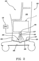
- the apparatus 100 comprises a support structure 101 internally exhibiting a housing chamber 102 which includes at least one liquid collection zone 103.
- the support structure exhibits at least one lateral wall 104 substantially delimiting the housing chamber 102.
- the lateral wall extends in a vertical direction, superiorly joining a terminal portion of head 105, while inferiorly exhibiting a terminal portion of base 106, which cooperate with the lateral wall 104 to define a box structure in which various components of the apparatus for dialysis are housed.
- Different support structures from those described can be included: for example the terminal base portion is absent in some machines and the lateral wall, in that case, defines a housing chamber that is inferiorly open.
- the support structure further comprises a bottom 107 arranged at a lower portion of the support structure.
- the bottom is located above the terminal base portion 106, if this is present, as in the illustrated embodiment.
- the bottom 107 comprises the liquid collection zone or zones 103 should these be more than one in number.
- the apparatus further comprises a hydraulic circuit 1.
- An embodiment of the hydraulic circuit is for example schematically illustrated in figure 1 . Note that the specific structure of the hydraulic circuit 1 is not relevant for the purposes of the present invention and therefore other and different circuits to those specifically shown in figure 1 might be used in consequence of the functional and design needs of each single medical apparatus.
- the hydraulic circuit 1 exhibits at least one supply channel 2, destined to transport a treatment liquid from at least one source 3 towards a treatment station 4 where one or more blood treatment units 5 operate.
- the circuit 1 further comprises at least one discharge channel 6, destined for the transport of a used liquid from the treatment station 4 towards an evacuation zone, schematically denoted by 7 in figure 1 .
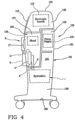
- the hydraulic circuit 1 is located in the housing chamber above the liquid collection zone 103, such that liquid leakage from the hydraulic circuit can at least partially accumulate at the liquid collection zone itself; figures 3 and 4 show that as for location, the hydraulic circuit 1 (schematically represented by a rectangular frame in a broken line) can be housed in the lower chamber 139, which, as will be more fully described herein below, constitutes one of the parts into which the housing chamber 102 is divided.
- the hydraulic circuit cooperates with a blood circuit 8, also schematically represented in figure 1 in its basis component parts.
- the specific structure of the blood circuit is also not fundamental, with reference to the present invention.
- a brief description of a possible embodiment of a blood circuit is made, which is however provided purely by way of non-limiting example.
- the blood circuit 8 of figure 1 comprises an arterial line 9 designed to remove blood from a vascular access 10 and a venous line 11 designed to return the treated blood to the vascular access.
- the blood circuit of figure 1 further comprises a first chamber, or blood chamber, 12 of the blood treatment unit 5, the second chamber 13 of which is connected to the hydraulic circuit 1.
- the arterial line is connected at the inlet to the blood chamber 12, while the venous line is connected at the output to the blood chamber 12.
- the supply channel 2 is connected at the inlet to the second chamber 13, while the discharge channel is connected at the outlet to the second chamber.
- the blood treatment unit 4 for example a dialyzer or an ultrafilter or a plasma filter or a hemofilter or a hemodiafilter, comprises, as mentioned, the two chambers 12 and 13 which are separated by a semipermeable membrane 14, for example of the hollow-fibre type or plate type.
- the blood circuit can also comprise one or more separators 15: in the example of figure 1 a separator 15 is included at the venous line 11, upstream of a safety valve 16.
- the valve 16 can be activated to close the venous line when, for example, for security reasons the blood return to the vascular access 10 has to be halted.
- the apparatus 100 can also comprise one or more blood pumps 17, for example positive displacement pumps such as peristaltic pumps; in the example of figure 1 , a pump 17 is included on the arterial line 9.
- the hydraulic circuit 1 is housed internally of the chamber 102.
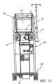
- the blood circuit 8 is instead borne on a front panel of the apparatus 100, which also supports the peristaltic pump or pumps 17.
- the treatment unit 5 can be physically supported by the lateral wall 104, and, in operating conditions of blood treatment, is connected both to the hydraulic circuit and to the blood circuit, as already illustrated (note that in figure 4 the blood circuit 8 and the unit 4 are represented with a broken line and schematically inasmuch as they are known).
- a liquid sensor 108 destined at least to detect any liquid in the liquid collection zone 103, operates in a distanced position with respect to the collection zone itself. More precisely, when, as in the illustrated embodiment, the support structure comprises a bottom 107 arranged at a lower portion of the support structure and comprising the liquid collection zone 103, the liquid sensor is located at a distanced position and is thus not in contact with the bottom 107.
- the senor Since the sensor is distanced from the bottom, it is easier to inspect and maintain. Further, the fact of being distanced from the collection zone means that insignificant leakage of liquid can be ignored.
- the senor should the sensor be operating internally of the housing chamber, it is located in a position which is distanced and vertically raised with respect to the liquid collection zone.
- the sensor can be distanced by 20-40 cm from the bottom.
- the sensor can operate in a measuring chamber located laterally and externally with respect to the housing chamber.
- the bottom 107 can exhibit a non-horizontal shape, as illustrated in the figures of the drawings in which the upper surface of the bottom converges in a downwards direction at an axially central zone of the bottom; in this case the liquid collection zone (in reality numerous collection zones could be provided in reciprocally distanced positions, and distributed throughout the bottom) is arranged in a zone of maximum depth of the bottom in order to receive, by free fall, any liquid leakage coming from the hydraulic circuit.
- the collection zone or zones are located on the bottom and receive and collect the liquid thanks to the position and geometry thereof.
- the bottom can comprise a wall 109 extending transversally of the lateral wall substantially at a base zone of the support structure.
- the liquid sensor is located in a distanced position with respect to the upper surface of the wall, i.e. it is not in contact with the surface, but operates either externally of the housing chamber or internally of the housing chamber, in which case it operates in a detached position from the bottom wall, which collects and conveys the liquid towards the collection chamber.
- the bottom wall extends over the whole transversal section of the container body and exhibits a perimeter edge 110 joined, for example sealingly, to the lateral wall 104, such that any substance falling from the components contained in the container body can be collected by the bottom wall.
- the bottom wall can extend such as to exhibit a perimeter edge 110 developing in proximity of and adjacently to an internal surface of the lateral wall.
- At least one measuring chamber 11 is arranged externally of the housing chamber 102 and a channel 112 which sets the liquid collection zone or zones in communication with the measuring chamber. Should more than one liquid collection zone be afforded on the bottom, several channels could be included, leading to a single measuring chamber or separate measuring chambers.
- Each channel 112 exhibits a first end, directly connected to a lower point 113a of the respective collection zone, and a second end 113b, directly connected at a lateral wall 114 of the measuring chamber 111.
- the liquid sensor operating in the measuring chamber or chambers it can comprise a liquid-presence sensor operating in the measuring chamber: i.e.
- the collection chamber can comprise an upper inspection opening 115 developing substantially horizontally and externally of the lateral wall 104 of the support structure in order to enable direct access to the measuring chamber and thus the sensor 108.
- the at least one liquid sensor 108 can comprise a member emitting a signal 116 and a receiver member 117 of the signal, the receiver member operating in the housing chamber above and at a predetermined distance from the bottom.
- the emitter member can operate internally of the housing chamber above and at a predetermined distance from the bottom, such as to emit a signal crossing the collection zone (and thus any liquid accumulated in the collection zone) to be then reflected from the upper surface of the bottom towards the receiver member.
- the receiver member according to the reflected signal received, can generate a measuring signal connected to the presence and/or the quantity of liquid present in the collection zone.
- the emitter member can operate on the bottom, for example at the collection zone.
- the emitter member and/or the receiver member can be constituted by a single member or a plurality of members adequately distributed on the transversal section of the housing chamber.
- the emitter member can comprise a member selected from a group comprising: an optical, acoustic, electric or electromagnetic signal emitter.
- the receiver can comprise a member selected from a group comprising: a receiver of an optical, acoustic, electric or electromagnetic type.
- the medical apparatus of any of the above-described embodiments can also comprise a user interface 118 and a programmed control unit 119 connected to the liquid sensor 108 and the user interface.
- the control unit 119 can for example comprise one or more digital microprocessor units or one or more analog units or other combinations of analog units and digital units. Relating by way of example to a microprocessor unit, once the unit has performed a special program (for example a program coming from outside or directly integrated on the microprocessor card), the unit is programmed, defining a plurality of functional blocks which constitute means each designed to perform respective operations.
- the programmed control unit defines:
- the medical apparatus can comprise at least one safety device operating at least the supply channel and commandable between at least one first operating condition, in which the safety device allows a liquid flow along the supply channel towards the treatment zone, and a second operative position, in which the safety device blocks passage of liquid towards the treatment zone.
- the control unit 119 can be connected to the safety device and programmed to define means for commanding the safety device to pass from the first to the second operative condition, should an alarm condition have been detected.
- the safety device can for example comprise at least one check member connected to the control unit: the check member in the first operating condition and on command of the control unit closes the fluid passage from the source along the supply channel.
- the safety device is a solenoid valve 120 controlled by the unit 119 as described above. Obviously a valve of another nature, either an occlusive pump or a further member able to selectively prevent and enable fluid passage can be used.
- the safety device can also comprise a bypass line 121 which connects the supply channel and the discharge channel, and one or more fluid check members 122 connected to the control unit for selectively opening and closing the bypass channel and the supply channel downstream of the bypass channel.
- the components 121 and 122, which can be alternative or additional to the presence of the member 120 are represented by a broken line in figure 1 .
- the check members 122 in the first operative condition and on command of the control unit close the fluid passage towards the treatment zone and connect the source with the discharge channel through the bypass line.
- pumps 2a and 6a can be included, located respectively on the lines 2 and 6 and also connected to the control unit 119.
- the medical apparatus for blood treatment can comprise various liquid sources (for example one or more water sources 3, one or more concentrate sources 123, 124, one or more sources of disinfectant liquids 125) connected to the supply channel 2 with respective delivery lines 126, 127 and 128, the medical apparatus can exhibit, at each delivery line, a respective check member 129, 130, 131 (for example comprising a valve member and/or an occlusive pump).
- liquid sources for example one or more water sources 3, one or more concentrate sources 123, 124, one or more sources of disinfectant liquids 125
- the medical apparatus can exhibit, at each delivery line, a respective check member 129, 130, 131 (for example comprising a valve member and/or an occlusive pump).
- the medical apparatus can comprise means for electrical supply (such as one or more sources, electrical filters and the necessary electric power components of known type and therefore not described in detail herein) connectable to an electric supply source external to the apparatus and destined to distribute electrical energy coming from the outside at tensions, currents and frequencies which are correct for the medical apparatus.
- the means for electric supply are schematically denoted by the block 132 and can be connected to the outside source, represented schematically by the block 140, with the interposing of means for selectively enabling and interrupting the electrical connection represented by the block 133.
- the programmed control unit 119 can be programmed to control means for selectively enabling and interrupting electrical energy 133 (such as for example a switch connected to the control unit) to the supply means on occurrence of the alarm condition.
- the support structure of the medical apparatus can comprise: a predetermined number of internal walls 134 which separate the housing chamber into the various sub-compartments:
- the programmed control unit can include:
- the senor is vertically distanced from the collection zone and the programmed control unit is programmed such that the alarm signal is generated before the liquid level reaches the sensor which is thus protected from immersion in the liquid.
- circuits of figure 1 should not be interpreted as defining or limiting, as an apparatus such as in the invention can comprise other additional or alternative components to those described.
- an ultrafiltration line can be included, with at least one respective pump connected to the discharge line.
- One or more infusion lines can also be included, with respective pumps or flow regulation valves, the infusion lines being connected up to the venous line 11 and/or the arterial line 9 and/or directly to the patient.
- the liquid sources can be prepackaged bags and/or liquids prepared by the apparatus itself.
- one or more pumps 2a, 6a and all the necessary temperature, pressure and concentration sensors can operate either on the supply line or on the discharge line, in order to adequately monitor the preparation and movement of the liquid in the hydraulic circuit.
Landscapes
- Health & Medical Sciences (AREA)
- Heart & Thoracic Surgery (AREA)
- Vascular Medicine (AREA)
- Animal Behavior & Ethology (AREA)
- Anesthesiology (AREA)
- Biomedical Technology (AREA)
- Hematology (AREA)
- Life Sciences & Earth Sciences (AREA)
- Engineering & Computer Science (AREA)
- General Health & Medical Sciences (AREA)
- Public Health (AREA)
- Veterinary Medicine (AREA)
- Urology & Nephrology (AREA)
- Cardiology (AREA)
- Emergency Medicine (AREA)
- External Artificial Organs (AREA)
Applications Claiming Priority (2)
| Application Number | Priority Date | Filing Date | Title |
|---|---|---|---|
| IT002397A ITMI20072397A1 (it) | 2007-12-20 | 2007-12-20 | Apparecchiatura medicale per il trattamento extracorporeo |
| PCT/IB2008/003504 WO2009090473A1 (en) | 2007-12-20 | 2008-12-16 | A medical apparatus for extracorporeal treatment |
Publications (3)
| Publication Number | Publication Date |
|---|---|
| EP2219705A1 EP2219705A1 (en) | 2010-08-25 |
| EP2219705B1 EP2219705B1 (en) | 2016-02-10 |
| EP2219705B2 true EP2219705B2 (en) | 2023-05-10 |
Family
ID=40315630
Family Applications (1)
| Application Number | Title | Priority Date | Filing Date |
|---|---|---|---|
| EP08871077.7A Active EP2219705B2 (en) | 2007-12-20 | 2008-12-16 | A medical apparatus for extracorporeal treatment |
Country Status (6)
| Country | Link |
|---|---|
| US (1) | US8679326B2 (it) |
| EP (1) | EP2219705B2 (it) |
| AU (1) | AU2008348034B2 (it) |
| CA (1) | CA2705628C (it) |
| IT (1) | ITMI20072397A1 (it) |
| WO (1) | WO2009090473A1 (it) |
Families Citing this family (9)
| Publication number | Priority date | Publication date | Assignee | Title |
|---|---|---|---|---|
| EP2730579A1 (en) | 2008-06-17 | 2014-05-14 | Millennium Pharmaceuticals, Inc. | Boronate ester compounds and pharmaceutical compositions thereof |
| US20110315237A1 (en) * | 2010-06-24 | 2011-12-29 | Keith Richard Jenkins | Dialysis machine and system with a dry external environment |
| DE102012103504A1 (de) | 2012-04-20 | 2013-10-24 | B. Braun Avitum Ag | Vorrichtung zur extrakorporalen Blutbehandlung mit Leckagesensor |
| WO2014106010A1 (en) * | 2012-12-31 | 2014-07-03 | Gambro Renal Products, Inc. | Pressure-based leak detection in extracorporeal blood treatment apparatus |
| DE102013102281A1 (de) * | 2013-03-07 | 2014-09-11 | B. Braun Avitum Ag | Dialysemaschine mit selbsttragendem Maschinengehäuse |
| US10465302B2 (en) | 2014-08-07 | 2019-11-05 | Marathon Systems, Inc. | Modular gaseous electrolysis apparatus with actively-cooled header module, co-disposed heat exchanger module and gas manifold modules therefor |
| EP3362118B2 (en) | 2015-10-14 | 2025-04-30 | Gambro Lundia AB | RENAL FAILURE THERAPY SYSTEM FOR ELECTRICALLY SAFE TREATMENT |
| US10682455B2 (en) * | 2017-07-11 | 2020-06-16 | Fresenius Medical Care Holdings, Inc. | Fluid leak detection in a dialysis machine |
| DE102022123642A1 (de) | 2022-09-15 | 2024-03-21 | B.Braun Avitum Ag | Leckageanschluss für eine Dialysemaschine, eine damit ausgerüstete Leckagekonstruktion sowie eine Dialysemaschine |
Citations (10)
| Publication number | Priority date | Publication date | Assignee | Title |
|---|---|---|---|---|
| US3713338A (en) † | 1971-01-18 | 1973-01-30 | Gen Motors Corp | Fiber optic liquid level indicator |
| US4805662A (en) † | 1988-01-21 | 1989-02-21 | Moody Ronald W | Hot water heater failure protection device with solenoid |
| WO1996022117A2 (en) † | 1995-01-17 | 1996-07-25 | Johnson & Johnson Corporation | On-line drug delivery system in extracorporeal therapy |
| WO1999002206A1 (en) † | 1997-07-09 | 1999-01-21 | Gambro Med Tech Ab | Method and arrangement for integrity-testing of a tube-set for use in a cycler for peritoneal dialysis |
| US20020000402A1 (en) † | 2000-06-30 | 2002-01-03 | Dillon Jack R. | Dialysis wall station |
| US20020062865A1 (en) † | 2000-11-08 | 2002-05-30 | Roger Harper | Plumbing flood control system |
| US20030126910A1 (en) † | 2002-01-04 | 2003-07-10 | Burbank Jeffrey H. | Method and apparatus for leak detection in blood circuits combining external fluid detection and air infiltration detection |
| US20050047959A1 (en) † | 2003-09-03 | 2005-03-03 | Matthias Brandl | Disinfecting and cleaning agent connection device |
| DE19655224B4 (de) † | 1995-02-13 | 2006-11-16 | Aksys, Ltd., Libertyville | Dialysattrennung in einem modularen Heimdialysesystem |
| US20080271527A1 (en) † | 2007-05-01 | 2008-11-06 | Hewitt John T | Liquid level sensor with level alarm |
Family Cites Families (13)
| Publication number | Priority date | Publication date | Assignee | Title |
|---|---|---|---|---|
| US3661119A (en) * | 1970-09-11 | 1972-05-09 | Oceanography Mariculture Ind | Larvae rearing tank and circulation system for fish culture |
| DE2927449A1 (de) * | 1979-07-06 | 1981-01-15 | Siemens Ag | Optoelektronischer fluessigkeitsdetektor |
| GB2199436A (en) | 1986-11-28 | 1988-07-06 | B & R Electrical Prod Ltd | Detection of fluid leakage |
| DE69217994T2 (de) * | 1991-07-25 | 1997-09-04 | Whitaker Corp | Flüssigkeitsstandsmesser |
| GB9223774D0 (en) | 1992-11-13 | 1993-01-06 | O Dea Francis J | Means for detecting water leakages from appliances |
| US5788099A (en) * | 1995-02-13 | 1998-08-04 | Akysys, Ltd. | Vessel for containing batch quantities of dialysate or other physiologic solution chemicals |
| US5932110A (en) * | 1995-02-13 | 1999-08-03 | Aksys, Ltd. | Dialysate conductivity adjustment in a batch dialysate preparation system |
| DE19516789B4 (de) | 1995-05-08 | 2006-05-11 | Sorin Group Deutschland Gmbh | Blutreservoirfüllstand-Überwachungsvorrichtung |
| US5938304A (en) * | 1998-08-17 | 1999-08-17 | Irby; John M. | Protective cover arrangement for dialysis machines |
| US6581461B1 (en) * | 2000-05-25 | 2003-06-24 | Trn Business Trust | Electro-optic sensor for levelmeter providing output signal with frequency modulated by surface level |
| DE10110540B4 (de) | 2001-03-05 | 2015-10-15 | Ruhr Oel Gmbh | Lagerbehälter für wassergefährdende Flüssigkeiten |
| JP2004329265A (ja) * | 2003-04-30 | 2004-11-25 | Teijin Ltd | 血液透析装置及び液体漏洩物検出方法 |
| US7291123B2 (en) * | 2003-06-04 | 2007-11-06 | Gambro Lundia | Joint for fluid transport lines for medical use |
-
2007
- 2007-12-20 IT IT002397A patent/ITMI20072397A1/it unknown
-
2008
- 2008-12-16 EP EP08871077.7A patent/EP2219705B2/en active Active
- 2008-12-16 AU AU2008348034A patent/AU2008348034B2/en active Active
- 2008-12-16 WO PCT/IB2008/003504 patent/WO2009090473A1/en not_active Ceased
- 2008-12-16 CA CA2705628A patent/CA2705628C/en active Active
- 2008-12-16 US US12/809,031 patent/US8679326B2/en active Active
Patent Citations (10)
| Publication number | Priority date | Publication date | Assignee | Title |
|---|---|---|---|---|
| US3713338A (en) † | 1971-01-18 | 1973-01-30 | Gen Motors Corp | Fiber optic liquid level indicator |
| US4805662A (en) † | 1988-01-21 | 1989-02-21 | Moody Ronald W | Hot water heater failure protection device with solenoid |
| WO1996022117A2 (en) † | 1995-01-17 | 1996-07-25 | Johnson & Johnson Corporation | On-line drug delivery system in extracorporeal therapy |
| DE19655224B4 (de) † | 1995-02-13 | 2006-11-16 | Aksys, Ltd., Libertyville | Dialysattrennung in einem modularen Heimdialysesystem |
| WO1999002206A1 (en) † | 1997-07-09 | 1999-01-21 | Gambro Med Tech Ab | Method and arrangement for integrity-testing of a tube-set for use in a cycler for peritoneal dialysis |
| US20020000402A1 (en) † | 2000-06-30 | 2002-01-03 | Dillon Jack R. | Dialysis wall station |
| US20020062865A1 (en) † | 2000-11-08 | 2002-05-30 | Roger Harper | Plumbing flood control system |
| US20030126910A1 (en) † | 2002-01-04 | 2003-07-10 | Burbank Jeffrey H. | Method and apparatus for leak detection in blood circuits combining external fluid detection and air infiltration detection |
| US20050047959A1 (en) † | 2003-09-03 | 2005-03-03 | Matthias Brandl | Disinfecting and cleaning agent connection device |
| US20080271527A1 (en) † | 2007-05-01 | 2008-11-06 | Hewitt John T | Liquid level sensor with level alarm |
Also Published As
| Publication number | Publication date |
|---|---|
| CA2705628A1 (en) | 2009-07-23 |
| EP2219705B1 (en) | 2016-02-10 |
| WO2009090473A1 (en) | 2009-07-23 |
| ITMI20072397A1 (it) | 2009-06-21 |
| AU2008348034B2 (en) | 2012-07-12 |
| US20100300945A1 (en) | 2010-12-02 |
| AU2008348034A1 (en) | 2009-07-23 |
| EP2219705A1 (en) | 2010-08-25 |
| US8679326B2 (en) | 2014-03-25 |
| CA2705628C (en) | 2014-05-06 |
Similar Documents
| Publication | Publication Date | Title |
|---|---|---|
| EP2219705B2 (en) | A medical apparatus for extracorporeal treatment | |
| EP2150290B1 (en) | A device for connecting to a liquid source | |
| ES2529095T3 (es) | Dispositivo con un casete para el tratamiento de un líquido médico | |
| KR101148716B1 (ko) | 체외 혈액 회로의 프라이밍 방법 및 장치 | |
| EP2091590B1 (en) | Hemo(dia)filtration apparatus | |
| CA2794828C (en) | Connector for a fluid transport line of a medical device | |
| CA2894387A1 (en) | Portable dialysis machine with improved reservoir heating system | |
| JP2015128644A (ja) | 外部機能手段、本発明に係る外部機能手段を受けるための血液処理機器、および、方法 | |
| WO2017001358A1 (en) | Extracorporeal blood circuit for single-needle treatments | |
| US11724019B2 (en) | Method and devices for emptying an effluent bag after blood treatment | |
| WO2017001357A1 (en) | Extracorporeal blood treatment apparatus for single-needle treatments | |
| JP2017520312A (ja) | 血液を吸引及び移送する装置 | |
| EP2091591B1 (en) | Medical fluid circuit unit | |
| US20240245840A1 (en) | Packaging Tray for a Blood Processing Kit | |
| US9127668B2 (en) | Apparatus for flowing fluids | |
| EP2091592B1 (en) | An extracorporeal blood chamber |
Legal Events
| Date | Code | Title | Description |
|---|---|---|---|
| PUAI | Public reference made under article 153(3) epc to a published international application that has entered the european phase |
Free format text: ORIGINAL CODE: 0009012 |
|
| 17P | Request for examination filed |
Effective date: 20100421 |
|
| AK | Designated contracting states |
Kind code of ref document: A1 Designated state(s): AT BE BG CH CY CZ DE DK EE ES FI FR GB GR HR HU IE IS IT LI LT LU LV MC MT NL NO PL PT RO SE SI SK TR |
|
| AX | Request for extension of the european patent |
Extension state: AL BA MK RS |
|
| DAX | Request for extension of the european patent (deleted) | ||
| 17Q | First examination report despatched |
Effective date: 20140220 |
|
| RIC1 | Information provided on ipc code assigned before grant |
Ipc: A61M 1/16 20060101AFI20150521BHEP Ipc: A61M 1/34 20060101ALI20150521BHEP Ipc: A61M 1/36 20060101ALI20150521BHEP |
|
| GRAP | Despatch of communication of intention to grant a patent |
Free format text: ORIGINAL CODE: EPIDOSNIGR1 |
|
| INTG | Intention to grant announced |
Effective date: 20150803 |
|
| GRAS | Grant fee paid |
Free format text: ORIGINAL CODE: EPIDOSNIGR3 |
|
| GRAA | (expected) grant |
Free format text: ORIGINAL CODE: 0009210 |
|
| AK | Designated contracting states |
Kind code of ref document: B1 Designated state(s): AT BE BG CH CY CZ DE DK EE ES FI FR GB GR HR HU IE IS IT LI LT LU LV MC MT NL NO PL PT RO SE SI SK TR |
|
| REG | Reference to a national code |
Ref country code: GB Ref legal event code: FG4D |
|
| REG | Reference to a national code |
Ref country code: AT Ref legal event code: REF Ref document number: 774330 Country of ref document: AT Kind code of ref document: T Effective date: 20160215 Ref country code: CH Ref legal event code: EP |
|
| REG | Reference to a national code |
Ref country code: IE Ref legal event code: FG4D |
|
| REG | Reference to a national code |
Ref country code: DE Ref legal event code: R096 Ref document number: 602008042334 Country of ref document: DE |
|
| REG | Reference to a national code |
Ref country code: LT Ref legal event code: MG4D |
|
| REG | Reference to a national code |
Ref country code: NL Ref legal event code: MP Effective date: 20160210 |
|
| REG | Reference to a national code |
Ref country code: AT Ref legal event code: MK05 Ref document number: 774330 Country of ref document: AT Kind code of ref document: T Effective date: 20160210 |
|
| PG25 | Lapsed in a contracting state [announced via postgrant information from national office to epo] |
Ref country code: NO Free format text: LAPSE BECAUSE OF FAILURE TO SUBMIT A TRANSLATION OF THE DESCRIPTION OR TO PAY THE FEE WITHIN THE PRESCRIBED TIME-LIMIT Effective date: 20160510 Ref country code: FI Free format text: LAPSE BECAUSE OF FAILURE TO SUBMIT A TRANSLATION OF THE DESCRIPTION OR TO PAY THE FEE WITHIN THE PRESCRIBED TIME-LIMIT Effective date: 20160210 Ref country code: IT Free format text: LAPSE BECAUSE OF FAILURE TO SUBMIT A TRANSLATION OF THE DESCRIPTION OR TO PAY THE FEE WITHIN THE PRESCRIBED TIME-LIMIT Effective date: 20160210 Ref country code: ES Free format text: LAPSE BECAUSE OF FAILURE TO SUBMIT A TRANSLATION OF THE DESCRIPTION OR TO PAY THE FEE WITHIN THE PRESCRIBED TIME-LIMIT Effective date: 20160210 Ref country code: GR Free format text: LAPSE BECAUSE OF FAILURE TO SUBMIT A TRANSLATION OF THE DESCRIPTION OR TO PAY THE FEE WITHIN THE PRESCRIBED TIME-LIMIT Effective date: 20160511 Ref country code: HR Free format text: LAPSE BECAUSE OF FAILURE TO SUBMIT A TRANSLATION OF THE DESCRIPTION OR TO PAY THE FEE WITHIN THE PRESCRIBED TIME-LIMIT Effective date: 20160210 |
|
| PG25 | Lapsed in a contracting state [announced via postgrant information from national office to epo] |
Ref country code: NL Free format text: LAPSE BECAUSE OF FAILURE TO SUBMIT A TRANSLATION OF THE DESCRIPTION OR TO PAY THE FEE WITHIN THE PRESCRIBED TIME-LIMIT Effective date: 20160210 Ref country code: PT Free format text: LAPSE BECAUSE OF FAILURE TO SUBMIT A TRANSLATION OF THE DESCRIPTION OR TO PAY THE FEE WITHIN THE PRESCRIBED TIME-LIMIT Effective date: 20160613 Ref country code: LV Free format text: LAPSE BECAUSE OF FAILURE TO SUBMIT A TRANSLATION OF THE DESCRIPTION OR TO PAY THE FEE WITHIN THE PRESCRIBED TIME-LIMIT Effective date: 20160210 Ref country code: AT Free format text: LAPSE BECAUSE OF FAILURE TO SUBMIT A TRANSLATION OF THE DESCRIPTION OR TO PAY THE FEE WITHIN THE PRESCRIBED TIME-LIMIT Effective date: 20160210 Ref country code: IS Free format text: LAPSE BECAUSE OF FAILURE TO SUBMIT A TRANSLATION OF THE DESCRIPTION OR TO PAY THE FEE WITHIN THE PRESCRIBED TIME-LIMIT Effective date: 20160610 Ref country code: PL Free format text: LAPSE BECAUSE OF FAILURE TO SUBMIT A TRANSLATION OF THE DESCRIPTION OR TO PAY THE FEE WITHIN THE PRESCRIBED TIME-LIMIT Effective date: 20160210 Ref country code: SE Free format text: LAPSE BECAUSE OF FAILURE TO SUBMIT A TRANSLATION OF THE DESCRIPTION OR TO PAY THE FEE WITHIN THE PRESCRIBED TIME-LIMIT Effective date: 20160210 Ref country code: LT Free format text: LAPSE BECAUSE OF FAILURE TO SUBMIT A TRANSLATION OF THE DESCRIPTION OR TO PAY THE FEE WITHIN THE PRESCRIBED TIME-LIMIT Effective date: 20160210 |
|
| PG25 | Lapsed in a contracting state [announced via postgrant information from national office to epo] |
Ref country code: EE Free format text: LAPSE BECAUSE OF FAILURE TO SUBMIT A TRANSLATION OF THE DESCRIPTION OR TO PAY THE FEE WITHIN THE PRESCRIBED TIME-LIMIT Effective date: 20160210 Ref country code: DK Free format text: LAPSE BECAUSE OF FAILURE TO SUBMIT A TRANSLATION OF THE DESCRIPTION OR TO PAY THE FEE WITHIN THE PRESCRIBED TIME-LIMIT Effective date: 20160210 |
|
| REG | Reference to a national code |
Ref country code: DE Ref legal event code: R026 Ref document number: 602008042334 Country of ref document: DE |
|
| REG | Reference to a national code |
Ref country code: FR Ref legal event code: PLFP Year of fee payment: 9 |
|
| PLBI | Opposition filed |
Free format text: ORIGINAL CODE: 0009260 |
|
| PG25 | Lapsed in a contracting state [announced via postgrant information from national office to epo] |
Ref country code: RO Free format text: LAPSE BECAUSE OF FAILURE TO SUBMIT A TRANSLATION OF THE DESCRIPTION OR TO PAY THE FEE WITHIN THE PRESCRIBED TIME-LIMIT Effective date: 20160210 Ref country code: SK Free format text: LAPSE BECAUSE OF FAILURE TO SUBMIT A TRANSLATION OF THE DESCRIPTION OR TO PAY THE FEE WITHIN THE PRESCRIBED TIME-LIMIT Effective date: 20160210 Ref country code: CZ Free format text: LAPSE BECAUSE OF FAILURE TO SUBMIT A TRANSLATION OF THE DESCRIPTION OR TO PAY THE FEE WITHIN THE PRESCRIBED TIME-LIMIT Effective date: 20160210 |
|
| PLAX | Notice of opposition and request to file observation + time limit sent |
Free format text: ORIGINAL CODE: EPIDOSNOBS2 |
|
| 26 | Opposition filed |
Opponent name: B. BRAUN AVITUM AG Effective date: 20161110 |
|
| PG25 | Lapsed in a contracting state [announced via postgrant information from national office to epo] |
Ref country code: BE Free format text: LAPSE BECAUSE OF FAILURE TO SUBMIT A TRANSLATION OF THE DESCRIPTION OR TO PAY THE FEE WITHIN THE PRESCRIBED TIME-LIMIT Effective date: 20160210 |
|
| PG25 | Lapsed in a contracting state [announced via postgrant information from national office to epo] |
Ref country code: BG Free format text: LAPSE BECAUSE OF FAILURE TO SUBMIT A TRANSLATION OF THE DESCRIPTION OR TO PAY THE FEE WITHIN THE PRESCRIBED TIME-LIMIT Effective date: 20160510 Ref country code: SI Free format text: LAPSE BECAUSE OF FAILURE TO SUBMIT A TRANSLATION OF THE DESCRIPTION OR TO PAY THE FEE WITHIN THE PRESCRIBED TIME-LIMIT Effective date: 20160210 |
|
| PLBB | Reply of patent proprietor to notice(s) of opposition received |
Free format text: ORIGINAL CODE: EPIDOSNOBS3 |
|
| REG | Reference to a national code |
Ref country code: CH Ref legal event code: PL |
|
| PG25 | Lapsed in a contracting state [announced via postgrant information from national office to epo] |
Ref country code: MC Free format text: LAPSE BECAUSE OF FAILURE TO SUBMIT A TRANSLATION OF THE DESCRIPTION OR TO PAY THE FEE WITHIN THE PRESCRIBED TIME-LIMIT Effective date: 20160210 |
|
| REG | Reference to a national code |
Ref country code: IE Ref legal event code: MM4A |
|
| PG25 | Lapsed in a contracting state [announced via postgrant information from national office to epo] |
Ref country code: LU Free format text: LAPSE BECAUSE OF NON-PAYMENT OF DUE FEES Effective date: 20161216 Ref country code: LI Free format text: LAPSE BECAUSE OF NON-PAYMENT OF DUE FEES Effective date: 20161231 Ref country code: CH Free format text: LAPSE BECAUSE OF NON-PAYMENT OF DUE FEES Effective date: 20161231 |
|
| PG25 | Lapsed in a contracting state [announced via postgrant information from national office to epo] |
Ref country code: IE Free format text: LAPSE BECAUSE OF NON-PAYMENT OF DUE FEES Effective date: 20161216 |
|
| REG | Reference to a national code |
Ref country code: FR Ref legal event code: PLFP Year of fee payment: 10 |
|
| PG25 | Lapsed in a contracting state [announced via postgrant information from national office to epo] |
Ref country code: CY Free format text: LAPSE BECAUSE OF FAILURE TO SUBMIT A TRANSLATION OF THE DESCRIPTION OR TO PAY THE FEE WITHIN THE PRESCRIBED TIME-LIMIT Effective date: 20160210 Ref country code: HU Free format text: LAPSE BECAUSE OF FAILURE TO SUBMIT A TRANSLATION OF THE DESCRIPTION OR TO PAY THE FEE WITHIN THE PRESCRIBED TIME-LIMIT; INVALID AB INITIO Effective date: 20081216 |
|
| PG25 | Lapsed in a contracting state [announced via postgrant information from national office to epo] |
Ref country code: TR Free format text: LAPSE BECAUSE OF FAILURE TO SUBMIT A TRANSLATION OF THE DESCRIPTION OR TO PAY THE FEE WITHIN THE PRESCRIBED TIME-LIMIT Effective date: 20160210 |
|
| APBM | Appeal reference recorded |
Free format text: ORIGINAL CODE: EPIDOSNREFNO |
|
| APBP | Date of receipt of notice of appeal recorded |
Free format text: ORIGINAL CODE: EPIDOSNNOA2O |
|
| APAH | Appeal reference modified |
Free format text: ORIGINAL CODE: EPIDOSCREFNO |
|
| APBQ | Date of receipt of statement of grounds of appeal recorded |
Free format text: ORIGINAL CODE: EPIDOSNNOA3O |
|
| PG25 | Lapsed in a contracting state [announced via postgrant information from national office to epo] |
Ref country code: MT Free format text: LAPSE BECAUSE OF NON-PAYMENT OF DUE FEES Effective date: 20161216 |
|
| REG | Reference to a national code |
Ref country code: FR Ref legal event code: PLFP Year of fee payment: 15 |
|
| APBU | Appeal procedure closed |
Free format text: ORIGINAL CODE: EPIDOSNNOA9O |
|
| PUAH | Patent maintained in amended form |
Free format text: ORIGINAL CODE: 0009272 |
|
| STAA | Information on the status of an ep patent application or granted ep patent |
Free format text: STATUS: PATENT MAINTAINED AS AMENDED |
|
| 27A | Patent maintained in amended form |
Effective date: 20230510 |
|
| AK | Designated contracting states |
Kind code of ref document: B2 Designated state(s): AT BE BG CH CY CZ DE DK EE ES FI FR GB GR HR HU IE IS IT LI LT LU LV MC MT NL NO PL PT RO SE SI SK TR |
|
| REG | Reference to a national code |
Ref country code: DE Ref legal event code: R102 Ref document number: 602008042334 Country of ref document: DE |
|
| PGFP | Annual fee paid to national office [announced via postgrant information from national office to epo] |
Ref country code: DE Payment date: 20251126 Year of fee payment: 18 |
|
| PGFP | Annual fee paid to national office [announced via postgrant information from national office to epo] |
Ref country code: GB Payment date: 20251119 Year of fee payment: 18 |
|
| PGFP | Annual fee paid to national office [announced via postgrant information from national office to epo] |
Ref country code: FR Payment date: 20251120 Year of fee payment: 18 |