EP2219400A1 - Performing diagnostics in a wireless system - Google Patents
Performing diagnostics in a wireless system Download PDFInfo
- Publication number
- EP2219400A1 EP2219400A1 EP10165852A EP10165852A EP2219400A1 EP 2219400 A1 EP2219400 A1 EP 2219400A1 EP 10165852 A EP10165852 A EP 10165852A EP 10165852 A EP10165852 A EP 10165852A EP 2219400 A1 EP2219400 A1 EP 2219400A1
- Authority
- EP
- European Patent Office
- Prior art keywords
- port
- diagnostic
- mobile device
- data
- processor
- Prior art date
- Legal status (The legal status is an assumption and is not a legal conclusion. Google has not performed a legal analysis and makes no representation as to the accuracy of the status listed.)
- Granted
Links
- 238000002405 diagnostic procedure Methods 0.000 claims abstract description 11
- 230000002457 bidirectional effect Effects 0.000 claims description 11
- 238000012360 testing method Methods 0.000 description 10
- 230000001413 cellular effect Effects 0.000 description 9
- 238000013480 data collection Methods 0.000 description 8
- 238000010586 diagram Methods 0.000 description 8
- 238000012545 processing Methods 0.000 description 8
- 238000000034 method Methods 0.000 description 6
- 238000012986 modification Methods 0.000 description 6
- 230000004048 modification Effects 0.000 description 6
- 238000013461 design Methods 0.000 description 5
- 238000004891 communication Methods 0.000 description 4
- 238000011161 development Methods 0.000 description 4
- 238000004519 manufacturing process Methods 0.000 description 4
- 230000009885 systemic effect Effects 0.000 description 4
- 230000006870 function Effects 0.000 description 3
- 230000000694 effects Effects 0.000 description 2
- 238000001727 in vivo Methods 0.000 description 2
- 230000005540 biological transmission Effects 0.000 description 1
- 239000000872 buffer Substances 0.000 description 1
- 238000006243 chemical reaction Methods 0.000 description 1
- 230000000295 complement effect Effects 0.000 description 1
- 230000001351 cycling effect Effects 0.000 description 1
- 230000010354 integration Effects 0.000 description 1
- 238000010295 mobile communication Methods 0.000 description 1
- 239000004065 semiconductor Substances 0.000 description 1
- 238000001228 spectrum Methods 0.000 description 1
- 238000010200 validation analysis Methods 0.000 description 1
Images


Classifications
-
- H—ELECTRICITY
- H04—ELECTRIC COMMUNICATION TECHNIQUE
- H04W—WIRELESS COMMUNICATION NETWORKS
- H04W24/00—Supervisory, monitoring or testing arrangements
-
- H—ELECTRICITY
- H04—ELECTRIC COMMUNICATION TECHNIQUE
- H04M—TELEPHONIC COMMUNICATION
- H04M1/00—Substation equipment, e.g. for use by subscribers
- H04M1/24—Arrangements for testing
-
- H—ELECTRICITY
- H04—ELECTRIC COMMUNICATION TECHNIQUE
- H04M—TELEPHONIC COMMUNICATION
- H04M1/00—Substation equipment, e.g. for use by subscribers
- H04M1/72—Mobile telephones; Cordless telephones, i.e. devices for establishing wireless links to base stations without route selection
- H04M1/724—User interfaces specially adapted for cordless or mobile telephones
- H04M1/72403—User interfaces specially adapted for cordless or mobile telephones with means for local support of applications that increase the functionality
Definitions
- the present invention relates to mobile systems, and more particularly to diagnostic testing of mobile systems.
- Effective system debugging requires some degree of visibility into the internal operation of the handset, which is limited on a production model.
- in vivo debugging of handsets is performed using an integrated test mode or a conventional trace facility.
- the integrated test mode typically provides limited diagnostic capabilities and only allows limited viewing of trace data on a display of the handset.
- Conventional trace facilities are typically accessed using a serial port of the handset, and the tracing is typically limited to analysis of data from an internal microcontroller unit (MCU).
- MCU microcontroller unit
- Such trace information does not provide any visibility into the physical layer (Layer 1 in the OSI communication model) or digital signal processor (DSP) data.
- a handset manufacturer may sometimes modify a handset to provide greater visibility.
- modifications are time consuming and are often ineffective.
- these modifications can vary operation of a handset to conceal problems, and may destroy the handset.
- these handsets cannot be sold after the modifications are made.
- an apparatus comprising: a first switch to route diagnostic information or acoustic information received from a processor; a codec coupled to the first switch to code the routed diagnostic information or acoustic information; and a second switch coupled to the codec to route the coded diagnostic information to a first port and to route the coded acoustic information to the first port or a second port.
- the processor may comprise a digital signal processor having a diagnostic port driver and an acoustic port driver.
- the apparatus may comprise a modem coupled between the diagnostic port driver and the first switch to modulate the diagnostic information.
- the apparatus may comprise a single integrated circuit including the first and second switches, the codec and the modem, and the modem may comprise a soft modem of the digital signal processor.
- the first port may comprise an external acoustic port of a handset.
- the external acoustic port may comprise a bidirectional port, and the bidirectional port may receive control information to cause the processor to generate the diagnostic information.
- the apparatus may comprise an unmodified production cellular handset, and the first port may comprise an external acoustic port and the second port may comprise an internal acoustic port.
- a method comprising: generating diagnostic information in a handset; providing the diagnostic information to an external acoustic port of the handset; and forwarding the diagnostic information to a data collector from the external acoustic port.
- the method may further comprise transmitting control signals to the handset from the data collector, the control signals to initiate a diagnostic mode in the handset.
- the method may further comprise modulating the diagnostic information and encoding the modulated diagnostic information via an integrated modem and codec of the handset before providing the diagnostic information to the external acoustic port.
- the method may further comprise receiving the diagnostic information from the external acoustic port at an interface unit and converting the diagnostic information to a selected protocol before forwarding the diagnostic information to the data collection unit.
- the method may further comprise: generating physical layer diagnostic information in a digital signal processor of the handset; modulating and coding the physical layer diagnostic information; and providing the modulated and coded physical layer diagnostic information to the external acoustic port.
- a mobile device comprising: a processor having a data port and a diagnostic port; first switch means for providing a path to the diagnostic port or the data port; an internal audio port coupled to the first switch means to communicate audio data with the processor; and an external audio port coupled to the first switch means to communicate diagnostic information between the processor and a data collector during a diagnostic procedure.
- the mobile device may further comprise a modem coupled between the diagnostic port of the processor and the first switch means.
- the mobile device may further comprise second switch means for providing a path between the modem and the data collector during the diagnostic procedure.
- the mobile device may further comprise a codec coupled between the first switch means and the second switch means.
- the mobile device may further comprise an integrated circuit including the processor, the modem, the first switch means, and the second switch means.
- the external audio port may comprise a bidirectional port to provide control information from the data collector to the mobile device and to provide the diagnostic information to the data collector.
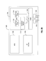
- FIG. 1 is a block diagram of a diagnostic setup for a handset in accordance with one embodiment of the present invention.
- FIG. 2A is a block diagram of an integrated circuit in accordance with one embodiment of the present invention.
- FIG. 2B is a block diagram of an integrated circuit in accordance with another embodiment of the present invention.
- FIG. 3 is a block diagram of a system in accordance with one embodiment of the present invention.
- a debug port of a wireless device may be used to inject control directives into and collect real-time trace data from the wireless device.
- any production device including the port may be used for diagnostic purposes.
- phone issues occurring in a specific phone can be debugged using that phone itself.
- a diagnostic mode may be entered without modification of the handset, and without compromising handset operational modes and functions, as described below.
- Virtually all cellular telephone handsets include a bidirectional acoustic port to which an external speaker and microphone can be attached.
- Embodiments of the invention "purloin” or co-opt this acoustic port for system debugging.
- a handset 10 which may be a cellular phone such as a global system for mobile communications (GSM) handset, is coupled for diagnostic testing.
- a bidirectional acoustic port 11 of handset 10 is coupled to a diagnostic interface unit (DIU) 15 via a cable 12. Diagnostic trace data generated within handset 10 may be transmitted through acoustic port 11 to DIU 15.
- DIU 15 may receive the trace data and convert it to a standard data protocol.
- DIU 15 may convert the trace data to a universal serial bus (USB) protocol or a recommended standard (e.g., RS-232) protocol. Then DIU 15 may forward the data to a data collection unit 20 via a cable 17.
- USB universal serial bus
- RS-232 recommended standard
- data collection unit 20 may be a personal computer such as a notebook computer.
- Data collection unit 20 may store the diagnostic information and also may display it on a display. In some embodiments the diagnostic information may be stored and then later accessed. In such manner, field tests can be performed and the data later analyzed.
- control directives may be forwarded through DIU 15 for use in controlling diagnostic testing of handset 10. Accordingly, DIU 15 may modulate the control directives and provide them to handset 10 via bidirectional acoustic port 11. These control directives may be passed to a digital signal processor (DSP) within handset 10 for execution of diagnostic routines.
- the diagnostic routines may include testing of lower level (e.g., physical) layers of the DSP.
- data collection unit 20 may include one or more storage media including instructions to perform diagnostic testing on a handset in accordance with an embodiment of the present invention. Further, the instructions may control storage and access to diagnostic trace data in data collection unit 20.
- IC 100 may be an ASIC adapted for use in a handset. More specifically, IC 100 may be a single chip integrated circuit that includes both radio frequency (RF) circuitry and baseband circuitry for use in a cellular phone or other wireless communication device.
- RF radio frequency
- IC 100 includes a DSP 110.
- DSP 110 may perform various baseband signal processing activities. These activities may include performing different algorithms to implement desired signal processing functions.
- ASIC 100 includes a microcontroller unit (MCU) 140 and RF circuitry 150. MCU 140 may be adapted to execute control applications and handle other functions of ASIC 100.
- RF circuitry 150 may include transceiver circuitry to both receive and transmit RF signals and convert these signals to and from baseband levels. Accordingly, baseband signals from DSP 110 may be provided to RF circuitry 150 for transmission, and incoming RF signals received by RF circuitry 150 may be converted to baseband and provided to DSP 110 for further processing. While not shown in FIG. 2A , it is to be understood that ASIC 100 may include other components, functionality, ports, and the like.
- DSP 110 may include a trace port driver 112 and a codec port driver 114.
- Trace port driver 112 may be used as a port to transmit and receive trace information during a diagnostic mode.
- Codec port driver 114 may be used to transmit and receive digital audio data during normal operation.
- trace port driver 112 is coupled to a voiceband modem 115.
- Modem 115 is used to modulate trace data in a format compatible with the remainder of IC 100. More specifically, modem 115 modulates the data to be compatible with a codec 120 in terms of bandwidth, circuit noise, and the like.
- a CCITT standard acoustic modem e.g., a V.94 modem
- a custom modem may be provided. In some embodiments such a custom modem may provide higher data rates, as the trace information does not traverse a telephone network. That is, in some embodiments an acoustic port may accommodate data rates roughly comparable to those of a serial port of the handset, for example, between approximately 50-60 kilobytes per second (kbps), although the scope of the present invention is not so limited.
- data from trace port driver 112 is modulated in modem 115 and is switched through a first switch S1 to a codec 120.
- This diagnostic mode is shown in FIG. 2A , in which switch S1 is selected to couple modem 115 to codec 120.
- Codec 120 may perform various encoding operations.
- Coded diagnostic information may then be switched through a second switch S2 to an external acoustic port 130 of IC 100.
- External acoustic port 130 may be a bidirectional port to both receive and transmit information.
- port 130 is coupled to external acoustic port 11 of handset 10, for example, via signal lines on a circuit board of the handset.
- acoustic ports 130 and 135 are bidirectional, providing output data in one direction (i.e., downlink to an external or internal speaker) and incoming information in the other direction (i.e., uplink via a microphone or other input).
- a plug detector may determine presence of a plug in external acoustic port 11.
- the plug detector may route signals to and from an external speaker/microphone connected to external acoustic port 11. However, in various embodiments during a diagnostic mode, this plug detector may be disabled to force route a path from DSP 110 (and more specifically trace port driver 112) through external acoustic port 130 of ASIC 100 via switches S1 and S2. Thus, during a diagnostic mode the audio path may be force routed through the external acoustic audio port, and any mechanism present in the handset for detecting the presence of a plug within the external acoustic port may be disabled.
- DSP 110b includes a voiceband modem 115b, in addition to a trace port driver 112b and a codec port driver 114b. Furthermore, DSP 110b includes a switch S1 to select between a path with trace port driver 112b or codec port driver 114b.
- IC 100b may correspond to IC 100 discussed above with regard to FIG. 2A .
- the external acoustic port of a handset may be used.
- an integrated test mode may be used to assign the external acoustic port for use in a diagnostic mode.
- other manners of allocating an external acoustic port to a diagnostic mode may be realized.
- the external acoustic port When allocated to diagnostic service, the external acoustic port may remain in a diagnostic mode until one of several conditions occurs. In some embodiments, these conditions may include one of the following: (1) manual disabling of the diagnostic mode; (2) cycling of power on the handset; or (3) removing a power source from the handset (e.g., a battery).
- the data may include information regarding operation of the DSP itself, along with physical layer data.
- Such data in the downlink direction may take various forms including, for example, log points, internal state data, and the like.
- diagnostic data to be captured may include low level data including, for example, I and Q data. Because such data may exist at higher bandwidths than may be accommodated via an external acoustic port, such data may be filtered and/or buffered, as described below.
- the connection from DIU 15 may carry control directives, which may take different forms.
- the control directives may include, for example, enabling/disabling of specific trace points, querying of memory contents, modifying of internal states, and the like.
- Trace data may be processed in various forms before it is sent in the downlink direction.
- the trace data may be filtered and/or buffered.
- trace data may conform to or match a speed of the link through bidirectional acoustic port 11.
- the link may have a speed of between approximately 50-60 kbps.
- one or more buffers within DSP 110 may be used to store the trace data before it is sent through trace port driver 112.
- the trace data may be filtered. For example, only trace data that corresponds to a particular type of event (e.g., physical layer data, failure information or the like) may be sent.
- code may be instrumented to generate trace data only for occurrences of certain events within the code.
- intermittent problems and/or problems that are hard to reproduce may be debugged. For example, issues relating to cell handover, dropping of calls and the like may be more readily debugged via field testing using a diagnostic setup in accordance with an embodiment of the present invention.
- system 300 may be a wireless device, such as a cellular telephone, PDA, portable computer or the like.
- An antenna 305 is present to receive and transmit RF signals.
- Antenna 305 may receive different bands of incoming RF signals using an antenna switch.
- a quad-band receiver may be adapted to receive GSM communications, enhanced GSM (EGSM), digital cellular system (DCS) and personal communication system (PCS) signals, although the scope of the present invention is not so limited.
- antenna 305 may be adapted for use in a general packet radio service (GPRS) device, a satellite tuner, or a wireless local area network (WLAN) device, for example.
- GPRS general packet radio service
- WLAN wireless local area network
- Transceiver 310 may be a single chip transceiver including both RF components and baseband components.
- Transceiver 310 may be formed using a complementary metal-oxide-semiconductor (CMOS) process, in some embodiments.
- CMOS complementary metal-oxide-semiconductor
- transceiver 310 includes an RF transceiver 312 and a baseband processor 314.
- RF transceiver 312 may include receive and transmit portions and may be adapted to provide frequency conversion between the RF spectrum and a baseband. Baseband signals are then provided to a baseband processor 314 for further processing.
- transceiver 310 may correspond to ASIC 100 of FIG. 2A .
- baseband processor 314 which may correspond to DSP 110 of FIG. 2A , may include a trace port driver and a codec port driver (not shown in FIG. 3 ).
- these ports may be coupled through the modem, codec and switches shown in FIG. 2A (not shown for ease of illustration in FIG. 3 ) to an external acoustic port 316 and an internal acoustic port 318.
- external acoustic port 316 may be coupled to a bidirectional external acoustic port 311 of handset 300.
- Internal acoustic port 318 may be coupled to an internal speaker 360 to provide voice data to an end user.
- Internal acoustic port 318 also may be coupled to an internal microphone 370 to receive voice data from the end user.
- baseband processor 314 may provide such signals to various locations within system 300 including, for example, an application processor 320 and a memory 330.
- Application processor 320 may be a microprocessor, such as a central processing unit (CPU) to control operation of system 300 and further handle processing of application programs, such as personal information management (PIM) programs, email programs, downloaded games, and the like.
- Memory 330 may include different memory components, such as a flash memory and a read only memory (ROM), although the scope of the present invention is not so limited.
- a display 340 is shown coupled to application processor 320 to provide display of information associated with telephone calls and application programs, for example.
- a keypad 350 may be present in system 300 to receive user input.
Landscapes
- Engineering & Computer Science (AREA)
- Signal Processing (AREA)
- Computer Networks & Wireless Communication (AREA)
- Human Computer Interaction (AREA)
- Telephone Function (AREA)
- Mobile Radio Communication Systems (AREA)
- Monitoring And Testing Of Transmission In General (AREA)
- Transceivers (AREA)
- Amplifiers (AREA)
- Electric Cable Installation (AREA)
- Testing, Inspecting, Measuring Of Stereoscopic Televisions And Televisions (AREA)
Abstract
Description
- The present invention relates to mobile systems, and more particularly to diagnostic testing of mobile systems.
- Many different types of mobile systems exist. Examples of such systems include cellular telephone handsets, personal digital assistants (PDAs), notebook personal computers (PCs), and the like. During the design and development of such systems, significant resources are spent to confirm that the design and its implementation operate satisfactorily, both in laboratory testing and in the field during normal operation.
- With respect to cellular telephones, for example, certain design issues may lead to systemic errors or performance issues that cannot be resolved during design phases or analysis of development or other prototype systems. Instead, such issues often arise only in the context of production systems. As a result, the final round of test and validation for a cellular handset is a systemic problem. All of the components of the phone may meet their respective specifications, but the unit as a whole may fail to meet one or more performance criteria, for a number of reasons. Many of these integration problems are inherently systemic and cannot be reproduced on a reference design, a development platform, or another handset model. Instead, such problems are debugged "in vivo" on the given handset model, and in some cases a specific handset.
- Effective system debugging requires some degree of visibility into the internal operation of the handset, which is limited on a production model. Typically, in vivo debugging of handsets is performed using an integrated test mode or a conventional trace facility. The integrated test mode typically provides limited diagnostic capabilities and only allows limited viewing of trace data on a display of the handset. Conventional trace facilities are typically accessed using a serial port of the handset, and the tracing is typically limited to analysis of data from an internal microcontroller unit (MCU). Such trace information does not provide any visibility into the physical layer (
Layer 1 in the OSI communication model) or digital signal processor (DSP) data. - Instead, to obtain such data a handset manufacturer may sometimes modify a handset to provide greater visibility. However, such modifications are time consuming and are often ineffective. For example, these modifications can vary operation of a handset to conceal problems, and may destroy the handset. Certainly, these handsets cannot be sold after the modifications are made. Nor are they generally suitable for field-testing of specific phone issues.
- Accordingly, improved diagnostics for mobile systems would aid and speed handset development and debugging.
- There is provided according to a first embodiment an apparatus comprising: a first switch to route diagnostic information or acoustic information received from a processor; a codec coupled to the first switch to code the routed diagnostic information or acoustic information; and a second switch coupled to the codec to route the coded diagnostic information to a first port and to route the coded acoustic information to the first port or a second port.
- The processor may comprise a digital signal processor having a diagnostic port driver and an acoustic port driver. The apparatus may comprise a modem coupled between the diagnostic port driver and the first switch to modulate the diagnostic information. The apparatus may comprise a single integrated circuit including the first and second switches, the codec and the modem, and the modem may comprise a soft modem of the digital signal processor. The first port may comprise an external acoustic port of a handset. The external acoustic port may comprise a bidirectional port, and the bidirectional port may receive control information to cause the processor to generate the diagnostic information. The apparatus may comprise an unmodified production cellular handset, and the first port may comprise an external acoustic port and the second port may comprise an internal acoustic port.
- There is provided according to a second embodiment a method comprising: generating diagnostic information in a handset; providing the diagnostic information to an external acoustic port of the handset; and forwarding the diagnostic information to a data collector from the external acoustic port.
- The method may further comprise transmitting control signals to the handset from the data collector, the control signals to initiate a diagnostic mode in the handset. The method may further comprise modulating the diagnostic information and encoding the modulated diagnostic information via an integrated modem and codec of the handset before providing the diagnostic information to the external acoustic port. The method may further comprise receiving the diagnostic information from the external acoustic port at an interface unit and converting the diagnostic information to a selected protocol before forwarding the diagnostic information to the data collection unit. The method may further comprise: generating physical layer diagnostic information in a digital signal processor of the handset; modulating and coding the physical layer diagnostic information; and providing the modulated and coded physical layer diagnostic information to the external acoustic port.
- There is provided according to a third embodiment a mobile device comprising: a processor having a data port and a diagnostic port; first switch means for providing a path to the diagnostic port or the data port; an internal audio port coupled to the first switch means to communicate audio data with the processor; and an external audio port coupled to the first switch means to communicate diagnostic information between the processor and a data collector during a diagnostic procedure.
- The mobile device may further comprise a modem coupled between the diagnostic port of the processor and the first switch means. The mobile device may further comprise second switch means for providing a path between the modem and the data collector during the diagnostic procedure. The mobile device may further comprise a codec coupled between the first switch means and the second switch means. The mobile device may further comprise an integrated circuit including the processor, the modem, the first switch means, and the second switch means. The external audio port may comprise a bidirectional port to provide control information from the data collector to the mobile device and to provide the diagnostic information to the data collector.
-
FIG. 1 is a block diagram of a diagnostic setup for a handset in accordance with one embodiment of the present invention. -
FIG. 2A is a block diagram of an integrated circuit in accordance with one embodiment of the present invention. -
FIG. 2B is a block diagram of an integrated circuit in accordance with another embodiment of the present invention. -
FIG. 3 is a block diagram of a system in accordance with one embodiment of the present invention. - In various embodiments of the present invention, a debug port of a wireless device is provided that may be used to inject control directives into and collect real-time trace data from the wireless device. Thus any production device including the port may be used for diagnostic purposes. As a result, phone issues occurring in a specific phone can be debugged using that phone itself. Furthermore, a diagnostic mode may be entered without modification of the handset, and without compromising handset operational modes and functions, as described below.
- Virtually all cellular telephone handsets include a bidirectional acoustic port to which an external speaker and microphone can be attached. Embodiments of the invention "purloin" or co-opt this acoustic port for system debugging.
- Referring now to
FIG. 1 , shown is a block diagram of a diagnostic setup for a handset in accordance with one embodiment of the present invention. As shown inFIG. 1 , ahandset 10, which may be a cellular phone such as a global system for mobile communications (GSM) handset, is coupled for diagnostic testing. Specifically, as shown inFIG. 1 , a bidirectionalacoustic port 11 ofhandset 10 is coupled to a diagnostic interface unit (DIU) 15 via acable 12. Diagnostic trace data generated withinhandset 10 may be transmitted throughacoustic port 11 toDIU 15. DIU 15 may receive the trace data and convert it to a standard data protocol. For example, in some embodiments DIU 15 may convert the trace data to a universal serial bus (USB) protocol or a recommended standard (e.g., RS-232) protocol. Then DIU 15 may forward the data to adata collection unit 20 via acable 17. In other embodiments, an interface unit may be omitted, and thehandset 10 may be coupled directly todata collection unit 20. In various embodiments,data collection unit 20 may be a personal computer such as a notebook computer.Data collection unit 20 may store the diagnostic information and also may display it on a display. In some embodiments the diagnostic information may be stored and then later accessed. In such manner, field tests can be performed and the data later analyzed. - Furthermore, using
data collection unit 20, control directives may be forwarded throughDIU 15 for use in controlling diagnostic testing ofhandset 10. Accordingly,DIU 15 may modulate the control directives and provide them tohandset 10 via bidirectionalacoustic port 11. These control directives may be passed to a digital signal processor (DSP) withinhandset 10 for execution of diagnostic routines. The diagnostic routines may include testing of lower level (e.g., physical) layers of the DSP. Thusdata collection unit 20 may include one or more storage media including instructions to perform diagnostic testing on a handset in accordance with an embodiment of the present invention. Further, the instructions may control storage and access to diagnostic trace data indata collection unit 20. - Referring now to
FIG. 2A , shown is a block diagram of an integrated circuit (IC) 100 in accordance with one embodiment of the present invention.IC 100 may be an ASIC adapted for use in a handset. More specifically,IC 100 may be a single chip integrated circuit that includes both radio frequency (RF) circuitry and baseband circuitry for use in a cellular phone or other wireless communication device. - As shown in
FIG. 2A ,IC 100 includes aDSP 110.DSP 110 may perform various baseband signal processing activities. These activities may include performing different algorithms to implement desired signal processing functions. As further shown inFIG. 2A ,ASIC 100 includes a microcontroller unit (MCU) 140 andRF circuitry 150.MCU 140 may be adapted to execute control applications and handle other functions ofASIC 100.RF circuitry 150 may include transceiver circuitry to both receive and transmit RF signals and convert these signals to and from baseband levels. Accordingly, baseband signals fromDSP 110 may be provided toRF circuitry 150 for transmission, and incoming RF signals received byRF circuitry 150 may be converted to baseband and provided toDSP 110 for further processing. While not shown inFIG. 2A , it is to be understood thatASIC 100 may include other components, functionality, ports, and the like. - As shown in
FIG. 2A ,DSP 110 may include atrace port driver 112 and acodec port driver 114.Trace port driver 112 may be used as a port to transmit and receive trace information during a diagnostic mode.Codec port driver 114 may be used to transmit and receive digital audio data during normal operation. - Still referring to
FIG. 2A , traceport driver 112 is coupled to avoiceband modem 115.Modem 115 is used to modulate trace data in a format compatible with the remainder ofIC 100. More specifically,modem 115 modulates the data to be compatible with acodec 120 in terms of bandwidth, circuit noise, and the like. In some embodiments, a CCITT standard acoustic modem (e.g., a V.94 modem) may be used. Alternately, a custom modem may be provided. In some embodiments such a custom modem may provide higher data rates, as the trace information does not traverse a telephone network. That is, in some embodiments an acoustic port may accommodate data rates roughly comparable to those of a serial port of the handset, for example, between approximately 50-60 kilobytes per second (kbps), although the scope of the present invention is not so limited. - During diagnostic modes, data from
trace port driver 112 is modulated inmodem 115 and is switched through a first switch S1 to acodec 120. This diagnostic mode is shown inFIG. 2A , in which switch S1 is selected tocouple modem 115 tocodec 120.Codec 120 may perform various encoding operations. Coded diagnostic information may then be switched through a second switch S2 to an externalacoustic port 130 ofIC 100. Externalacoustic port 130 may be a bidirectional port to both receive and transmit information. In turn,port 130 is coupled to externalacoustic port 11 ofhandset 10, for example, via signal lines on a circuit board of the handset. - During normal operation, voice processing is performed in
DSP 110 and digitized data fromcodec port driver 114 is coupled via switch S1 throughcodec 120 and switch S2 to either externalacoustic port 130 or an internalacoustic port 135 ofIC 100, based on whether an external speaker/microphone is present. As shown inFIG. 2A ,acoustic ports acoustic port 11. If a plug is present, the plug detector may route signals to and from an external speaker/microphone connected to externalacoustic port 11. However, in various embodiments during a diagnostic mode, this plug detector may be disabled to force route a path from DSP 110 (and more specifically trace port driver 112) through externalacoustic port 130 ofASIC 100 via switches S1 and S2. Thus, during a diagnostic mode the audio path may be force routed through the external acoustic audio port, and any mechanism present in the handset for detecting the presence of a plug within the external acoustic port may be disabled. - In other embodiments, additional functionality may be implemented within
DSP 110. For example, a voiceband modem may be implemented in software (i.e., a soft modem) for execution withinDSP 110. Referring now toFIG. 2B , shown is a block diagram of anintegrated circuit 100b in accordance with another embodiment of the present invention. As shown inFIG. 2B ,DSP 110b includes avoiceband modem 115b, in addition to atrace port driver 112b and acodec port driver 114b. Furthermore,DSP 110b includes a switch S1 to select between a path withtrace port driver 112b orcodec port driver 114b. In all other respects,IC 100b may correspond toIC 100 discussed above with regard toFIG. 2A . - Accordingly, to perform diagnostics the external acoustic port of a handset may be used. In some embodiments, an integrated test mode may be used to assign the external acoustic port for use in a diagnostic mode. However, other manners of allocating an external acoustic port to a diagnostic mode may be realized. When allocated to diagnostic service, the external acoustic port may remain in a diagnostic mode until one of several conditions occurs. In some embodiments, these conditions may include one of the following: (1) manual disabling of the diagnostic mode; (2) cycling of power on the handset; or (3) removing a power source from the handset (e.g., a battery).
- While the types of diagnostic trace information may vary in different embodiments, in some embodiments the data may include information regarding operation of the DSP itself, along with physical layer data. Such data in the downlink direction may take various forms including, for example, log points, internal state data, and the like. Furthermore, diagnostic data to be captured may include low level data including, for example, I and Q data. Because such data may exist at higher bandwidths than may be accommodated via an external acoustic port, such data may be filtered and/or buffered, as described below. In the uplink direction, the connection from
DIU 15 may carry control directives, which may take different forms. In some embodiments, the control directives may include, for example, enabling/disabling of specific trace points, querying of memory contents, modifying of internal states, and the like. - Trace data may be processed in various forms before it is sent in the downlink direction. For example, the trace data may be filtered and/or buffered. In such manner, trace data may conform to or match a speed of the link through bidirectional
acoustic port 11. As discussed above, in some embodiments the link may have a speed of between approximately 50-60 kbps. To accommodate this speed, one or more buffers withinDSP 110 may be used to store the trace data before it is sent throughtrace port driver 112. Furthermore, the trace data may be filtered. For example, only trace data that corresponds to a particular type of event (e.g., physical layer data, failure information or the like) may be sent. For example, code may be instrumented to generate trace data only for occurrences of certain events within the code. - By performing testing in accordance with an embodiment of the present invention, intermittent problems and/or problems that are hard to reproduce may be debugged. For example, issues relating to cell handover, dropping of calls and the like may be more readily debugged via field testing using a diagnostic setup in accordance with an embodiment of the present invention.
- Because the external acoustic port is used for diagnostic purposes, the ability to listen to real audio during diagnostic modes may be precluded. However, while certain problems may manifest themselves as audio problems, the vast majority of problems are not in fact audio problems, but rather systemic issues, as described herein. Thus although real audio data may not be available during a diagnostic mode, successful debugging may occur.
- Referring now to
FIG. 3 , shown is a block diagram of a system in accordance with one embodiment of the present invention. As shown inFIG. 3 ,system 300 may be a wireless device, such as a cellular telephone, PDA, portable computer or the like. Anantenna 305 is present to receive and transmit RF signals.Antenna 305 may receive different bands of incoming RF signals using an antenna switch. For example, a quad-band receiver may be adapted to receive GSM communications, enhanced GSM (EGSM), digital cellular system (DCS) and personal communication system (PCS) signals, although the scope of the present invention is not so limited. In other embodiments,antenna 305 may be adapted for use in a general packet radio service (GPRS) device, a satellite tuner, or a wireless local area network (WLAN) device, for example. - Incoming RF signals are provided to a
transceiver 310 which may be a single chip transceiver including both RF components and baseband components.Transceiver 310 may be formed using a complementary metal-oxide-semiconductor (CMOS) process, in some embodiments. As shown inFIG. 3 ,transceiver 310 includes anRF transceiver 312 and abaseband processor 314.RF transceiver 312 may include receive and transmit portions and may be adapted to provide frequency conversion between the RF spectrum and a baseband. Baseband signals are then provided to abaseband processor 314 for further processing. - In some embodiments,
transceiver 310 may correspond toASIC 100 ofFIG. 2A . Accordingly,baseband processor 314, which may correspond toDSP 110 ofFIG. 2A , may include a trace port driver and a codec port driver (not shown inFIG. 3 ). In turn, these ports may be coupled through the modem, codec and switches shown inFIG. 2A (not shown for ease of illustration inFIG. 3 ) to an externalacoustic port 316 and an internalacoustic port 318. As shown inFIG. 3 , externalacoustic port 316 may be coupled to a bidirectional externalacoustic port 311 ofhandset 300. Internalacoustic port 318 may be coupled to aninternal speaker 360 to provide voice data to an end user. Internalacoustic port 318 also may be coupled to aninternal microphone 370 to receive voice data from the end user. - After processing signals received from
RF transceiver 312,baseband processor 314 may provide such signals to various locations withinsystem 300 including, for example, anapplication processor 320 and amemory 330.Application processor 320 may be a microprocessor, such as a central processing unit (CPU) to control operation ofsystem 300 and further handle processing of application programs, such as personal information management (PIM) programs, email programs, downloaded games, and the like.Memory 330 may include different memory components, such as a flash memory and a read only memory (ROM), although the scope of the present invention is not so limited. Additionally, adisplay 340 is shown coupled toapplication processor 320 to provide display of information associated with telephone calls and application programs, for example. Furthermore, akeypad 350 may be present insystem 300 to receive user input. - While the present invention has been described with respect to a limited number of embodiments, those skilled in the art will appreciate numerous modifications and variations therefrom. It is intended that the appended claims cover all such modifications and variations as fall within the true spirit and scope of this present invention.
Claims (11)
- A mobile device comprising:a processor having a data port and a diagnostic port;a first switch coupled to provide a path to the diagnostic port or the data port;an internal audio port coupled to the first switch to communicate audio data with the processor; andan external audio port coupled to the first switch means to communicate diagnostic information between the processor and a data collector during a diagnostic procedure.
- The mobile device of claim 1, further comprising a modem coupled between the diagnostic port of the processor and the first switch means.
- The mobile device of claim 2, further comprising a second switch coupled between the first switch means and the external audio port to provide a path between the modem and the data collector during the diagnostic procedure.
- The mobile device of claim 3, further comprising a codec coupled between the first switch means and the second switch means.
- The mobile device of claim 3, further comprising an integrated circuit including the processor, the modem, the first switch means, and the second switch means.
- The mobile device of claim 1, wherein the external audio port comprises a bidirectional port to provide control information from the data collector to the mobile device and to provide the diagnostic information to the data collector.
- The mobile device of any preceding claim wherein said processor is a digital signal processor.
- The mobile device of any preceding claim wherein during said diagnostic procedure an audio path is force routed through said external audio port.
- The mobile device of claim 8 wherein an ability to listen to audio during diagnostic modes is precluded.
- The mobile device of any preceding claim further comprising a plug detector configured to:determine the presence of a plug said external acoustic port route signals to and from said external acoustic port if a plug is detected.
- The mobile device of claim 10 wherein said plug detector is disabled during said diagnostic procedure.
Applications Claiming Priority (2)
| Application Number | Priority Date | Filing Date | Title |
|---|---|---|---|
| US11/152,136 US8260285B2 (en) | 2005-06-14 | 2005-06-14 | Performing diagnostics in a wireless system |
| EP06740118A EP1894432B1 (en) | 2005-06-14 | 2006-03-30 | Performing diagnostics in a wireless system |
Related Parent Applications (1)
| Application Number | Title | Priority Date | Filing Date |
|---|---|---|---|
| EP06740118.2 Division | 2006-03-30 |
Publications (2)
| Publication Number | Publication Date |
|---|---|
| EP2219400A1 true EP2219400A1 (en) | 2010-08-18 |
| EP2219400B1 EP2219400B1 (en) | 2012-01-18 |
Family
ID=36699279
Family Applications (2)
| Application Number | Title | Priority Date | Filing Date |
|---|---|---|---|
| EP06740118A Expired - Lifetime EP1894432B1 (en) | 2005-06-14 | 2006-03-30 | Performing diagnostics in a wireless system |
| EP10165852A Expired - Lifetime EP2219400B1 (en) | 2005-06-14 | 2006-03-30 | Performing diagnostics in a wireless system |
Family Applications Before (1)
| Application Number | Title | Priority Date | Filing Date |
|---|---|---|---|
| EP06740118A Expired - Lifetime EP1894432B1 (en) | 2005-06-14 | 2006-03-30 | Performing diagnostics in a wireless system |
Country Status (7)
| Country | Link |
|---|---|
| US (2) | US8260285B2 (en) |
| EP (2) | EP1894432B1 (en) |
| CN (1) | CN101243709B (en) |
| AT (2) | ATE542380T1 (en) |
| DE (1) | DE602006016602D1 (en) |
| TW (1) | TWI346495B (en) |
| WO (1) | WO2007001539A1 (en) |
Families Citing this family (12)
| Publication number | Priority date | Publication date | Assignee | Title |
|---|---|---|---|---|
| US8244237B2 (en) * | 2006-09-26 | 2012-08-14 | Samsung Electronics Co., Ltd. | Handset self diagnostics |
| US8369799B2 (en) | 2007-10-25 | 2013-02-05 | Echostar Technologies L.L.C. | Apparatus, systems and methods to communicate received commands from a receiving device to a mobile device |
| US8405512B2 (en) * | 2008-02-01 | 2013-03-26 | Apple Inc. | System and method for accessing diagnostic information |
| US7880591B2 (en) | 2008-02-01 | 2011-02-01 | Apple Inc. | Consumer abuse detection system and method |
| US8867571B2 (en) * | 2008-03-31 | 2014-10-21 | Echostar Technologies L.L.C. | Systems, methods and apparatus for transmitting data over a voice channel of a wireless telephone network |
| JP2011227743A (en) * | 2010-04-21 | 2011-11-10 | Sanyo Electric Co Ltd | Accessory device, information collection device and method for obtaining information on article return reason |
| US8996928B2 (en) * | 2012-04-17 | 2015-03-31 | Qualcomm Incorporated | Devices for indicating a physical layer error |
| US8942109B2 (en) | 2012-04-25 | 2015-01-27 | Anritsu Company | Impairment simulation for network communication to enable voice quality degradation estimation |
| US20150025818A1 (en) * | 2013-07-16 | 2015-01-22 | Azimuth Systems, Inc. | Synchronized testing of multiple wireless devices |
| DE102014213524A1 (en) * | 2014-07-11 | 2016-01-14 | Rohde & Schwarz GmbH & Co. Kommanditgesellschaft | Measuring system, measuring method and computer program product for resource-saving measurement |
| US10152432B1 (en) * | 2017-07-26 | 2018-12-11 | Dell Products L.P. | Support information provisioning system |
| RU2671999C1 (en) * | 2017-12-19 | 2018-11-08 | Общество с ограниченной ответственностью "Инновационные системы" | Method and system for diagnostics of mobile computer devices |
Citations (4)
| Publication number | Priority date | Publication date | Assignee | Title |
|---|---|---|---|---|
| WO2001084809A2 (en) * | 2000-04-27 | 2001-11-08 | Harris Corporation | Interface for conducting serial digital data communications through audio jack |
| EP1229747A2 (en) * | 2001-02-02 | 2002-08-07 | Mitsubishi Denki Kabushiki Kaisha | Mobile phone terminal, and peripheral unit for acoustic test of mobile phone terminal |
| EP1439719A1 (en) * | 2003-01-20 | 2004-07-21 | Thomson Licensing S.A. | Method for testing an appliance comprising an audio port and respective appliance |
| EP1441491A1 (en) * | 2003-01-21 | 2004-07-28 | Agilent Technologies, Inc. | System and method for testing portable communications devices |
Family Cites Families (25)
| Publication number | Priority date | Publication date | Assignee | Title |
|---|---|---|---|---|
| JP3183956B2 (en) | 1992-07-23 | 2001-07-09 | 日本電気株式会社 | Buffer memory circuit |
| US5426643A (en) * | 1993-11-01 | 1995-06-20 | Motorola Inc. | Apparatus and method for transmitting bit synchronous data over an unreliable channel |
| JPH07221761A (en) * | 1994-02-04 | 1995-08-18 | Fujitsu Ltd | Cell delay absorption circuit |
| DE4417286A1 (en) | 1994-05-13 | 1995-11-23 | Deutsche Bundespost Telekom | ATM buffer circuit data read-out method |
| US5586119A (en) * | 1994-08-31 | 1996-12-17 | Motorola, Inc. | Method and apparatus for packet alignment in a communication system |
| US5623483A (en) * | 1995-05-11 | 1997-04-22 | Lucent Technologies Inc. | Synchronization system for networked multimedia streams |
| US5781593A (en) * | 1996-11-14 | 1998-07-14 | Omnipoint Corporation | Methods and apparatus for vocoder synchronization in mobile communication network |
| US6064693A (en) * | 1997-02-28 | 2000-05-16 | Data Race, Inc. | System and method for handling underrun of compressed speech frames due to unsynchronized receive and transmit clock rates |
| DE69735527D1 (en) | 1997-05-02 | 2006-05-11 | Lsi Logic Corp | Digital method for adaptive clock recovery |
| US6493338B1 (en) * | 1997-05-19 | 2002-12-10 | Airbiquity Inc. | Multichannel in-band signaling for data communications over digital wireless telecommunications networks |
| KR100255328B1 (en) * | 1998-02-18 | 2000-05-01 | 윤종용 | Hand-held telephone for recording/reproducing of voice signal and method thereof |
| WO2000024144A1 (en) | 1998-10-21 | 2000-04-27 | Tiernan Communications, Inc. | Method and apparatus for de-jittering asynchronous data transfer delay |
| US6754265B1 (en) * | 1999-02-05 | 2004-06-22 | Honeywell International Inc. | VOCODER capable modulator/demodulator |
| US6658027B1 (en) * | 1999-08-16 | 2003-12-02 | Nortel Networks Limited | Jitter buffer management |
| US7010001B2 (en) * | 2000-01-10 | 2006-03-07 | Qualcomm, Incorporated | Method and apparatus for supporting adaptive multi-rate (AMR) data in a CDMA communication system |
| US8116759B2 (en) * | 2000-06-12 | 2012-02-14 | I/O Controls Corporation | System and method for facilitating diagnosis and maintenance of a mobile conveyance |
| US7460629B2 (en) * | 2001-06-29 | 2008-12-02 | Agere Systems Inc. | Method and apparatus for frame-based buffer control in a communication system |
| WO2003036895A1 (en) | 2001-10-25 | 2003-05-01 | Renesas Technology Corp. | Semiconductor integrated circuit for communication, modulating/demodulating device, and communication diagnosing method |
| US7162731B2 (en) | 2002-02-07 | 2007-01-09 | Advent Networks, Inc. | Radio frequency characterization of cable plant and corresponding calibration of communication equipment communicating via the cable plant |
| JP2003271734A (en) * | 2002-03-19 | 2003-09-26 | Nippon Colin Co Ltd | Diagnosis result notification method |
| JP2004072573A (en) | 2002-08-08 | 2004-03-04 | Murata Mach Ltd | Device and system for diagnosing apparatus and communication terminal apparatus |
| JP4218348B2 (en) | 2003-01-17 | 2009-02-04 | オムロン株式会社 | Imaging device |
| CN1522086A (en) * | 2003-02-12 | 2004-08-18 | 华冠通讯股份有限公司 | Automatic testing system and method for mobile phone functions |
| JP4390620B2 (en) * | 2004-04-30 | 2009-12-24 | Necエレクトロニクス株式会社 | Voltage regulator circuit |
| US7720046B2 (en) * | 2005-09-23 | 2010-05-18 | St-Ericsson Sa | Synchronizing a channel codec and vocoder of a mobile station |
-
2005
- 2005-06-14 US US11/152,136 patent/US8260285B2/en not_active Expired - Fee Related
-
2006
- 2006-03-30 WO PCT/US2006/011769 patent/WO2007001539A1/en not_active Ceased
- 2006-03-30 AT AT10165852T patent/ATE542380T1/en active
- 2006-03-30 EP EP06740118A patent/EP1894432B1/en not_active Expired - Lifetime
- 2006-03-30 EP EP10165852A patent/EP2219400B1/en not_active Expired - Lifetime
- 2006-03-30 DE DE602006016602T patent/DE602006016602D1/en not_active Expired - Lifetime
- 2006-03-30 AT AT06740118T patent/ATE480114T1/en not_active IP Right Cessation
- 2006-03-30 TW TW095111195A patent/TWI346495B/en not_active IP Right Cessation
- 2006-03-30 CN CN2006800294526A patent/CN101243709B/en not_active Expired - Fee Related
-
2012
- 2012-04-24 US US13/454,907 patent/US8538417B2/en not_active Expired - Fee Related
Patent Citations (4)
| Publication number | Priority date | Publication date | Assignee | Title |
|---|---|---|---|---|
| WO2001084809A2 (en) * | 2000-04-27 | 2001-11-08 | Harris Corporation | Interface for conducting serial digital data communications through audio jack |
| EP1229747A2 (en) * | 2001-02-02 | 2002-08-07 | Mitsubishi Denki Kabushiki Kaisha | Mobile phone terminal, and peripheral unit for acoustic test of mobile phone terminal |
| EP1439719A1 (en) * | 2003-01-20 | 2004-07-21 | Thomson Licensing S.A. | Method for testing an appliance comprising an audio port and respective appliance |
| EP1441491A1 (en) * | 2003-01-21 | 2004-07-28 | Agilent Technologies, Inc. | System and method for testing portable communications devices |
Also Published As
| Publication number | Publication date |
|---|---|
| US20060281452A1 (en) | 2006-12-14 |
| WO2007001539A1 (en) | 2007-01-04 |
| ATE542380T1 (en) | 2012-02-15 |
| DE602006016602D1 (en) | 2010-10-14 |
| EP2219400B1 (en) | 2012-01-18 |
| US8538417B2 (en) | 2013-09-17 |
| US20120208531A1 (en) | 2012-08-16 |
| EP1894432A1 (en) | 2008-03-05 |
| TW200644594A (en) | 2006-12-16 |
| CN101243709B (en) | 2011-09-14 |
| EP1894432B1 (en) | 2010-09-01 |
| US8260285B2 (en) | 2012-09-04 |
| ATE480114T1 (en) | 2010-09-15 |
| TWI346495B (en) | 2011-08-01 |
| CN101243709A (en) | 2008-08-13 |
Similar Documents
| Publication | Publication Date | Title |
|---|---|---|
| US8538417B2 (en) | Performing diagnostics in a wireless system | |
| CN101662530B (en) | Mobile phone with Bluetooth function and test method thereof | |
| KR100382932B1 (en) | Sharing interface apparatus for serial and usb port of mobile communication terminal | |
| JP3676244B2 (en) | Portable device terminal and peripheral device for acoustic test of portable device terminal | |
| US5504800A (en) | Cellular automated test set | |
| KR20020044176A (en) | System and method for indicating connection properties for a call placed via a wireless handset | |
| KR100574662B1 (en) | Mobile communication terminal with source program tracking and its control method | |
| AU698175B2 (en) | Portable multi-information communication device | |
| KR100663566B1 (en) | Connection cable and method for debugging wireless terminal | |
| US20080103776A1 (en) | Real time monitoring & control for audio devices | |
| KR20050073967A (en) | Method for controlling operation of stereo speaker in mobile communication terminal | |
| JPH11355857A (en) | Mobile phone | |
| KR20080033631A (en) | Mobile communication terminal comprising an ultra-wideband wireless communication module and its driving method | |
| KR100241897B1 (en) | Data transmitting and receiving device and method of composite wireless terminal | |
| CN121098374A (en) | Narrowband internet of things terminal, data transmission method, device, medium and product | |
| KR100575977B1 (en) | Link common method with PC in mobile communication terminal equipped with MP3 playback function | |
| KR20020039426A (en) | Simulator for verifying Radio Protocol in a CDMA Mobile Communication System | |
| JP2005025360A (en) | Electronic equipment | |
| JPH09284415A (en) | mobile phone | |
| JP2001144642A (en) | Wireless communication terminal | |
| KR20050100268A (en) | Apparatus and method for transmitting a short message in a mobile terminal | |
| JP2002027543A (en) | Digital data communication method and digital data communication device | |
| KR20050056608A (en) | Method for reporting error and user petition information of mobile communication unit | |
| KR20010028376A (en) | Digital picture image and data transmission cellular phone using ISM band | |
| KR980012958A (en) | Devices for data communication in digital mobile phones or PCS terminals |
Legal Events
| Date | Code | Title | Description |
|---|---|---|---|
| PUAI | Public reference made under article 153(3) epc to a published international application that has entered the european phase |
Free format text: ORIGINAL CODE: 0009012 |
|
| AC | Divisional application: reference to earlier application |
Ref document number: 1894432 Country of ref document: EP Kind code of ref document: P |
|
| AK | Designated contracting states |
Kind code of ref document: A1 Designated state(s): AT BE BG CH CY CZ DE DK EE ES FI FR GB GR HU IE IS IT LI LT LU LV MC NL PL PT RO SE SI SK TR |
|
| 17P | Request for examination filed |
Effective date: 20110202 |
|
| RIC1 | Information provided on ipc code assigned before grant |
Ipc: H04M 1/24 20060101ALI20110315BHEP Ipc: H04W 24/00 20090101AFI20110315BHEP |
|
| GRAP | Despatch of communication of intention to grant a patent |
Free format text: ORIGINAL CODE: EPIDOSNIGR1 |
|
| GRAS | Grant fee paid |
Free format text: ORIGINAL CODE: EPIDOSNIGR3 |
|
| RAP1 | Party data changed (applicant data changed or rights of an application transferred) |
Owner name: ST-ERICSSON SA |
|
| GRAA | (expected) grant |
Free format text: ORIGINAL CODE: 0009210 |
|
| AC | Divisional application: reference to earlier application |
Ref document number: 1894432 Country of ref document: EP Kind code of ref document: P |
|
| AK | Designated contracting states |
Kind code of ref document: B1 Designated state(s): AT BE BG CH CY CZ DE DK EE ES FI FR GB GR HU IE IS IT LI LT LU LV MC NL PL PT RO SE SI SK TR |
|
| REG | Reference to a national code |
Ref country code: GB Ref legal event code: FG4D |
|
| REG | Reference to a national code |
Ref country code: CH Ref legal event code: EP |
|
| REG | Reference to a national code |
Ref country code: AT Ref legal event code: REF Ref document number: 542380 Country of ref document: AT Kind code of ref document: T Effective date: 20120215 Ref country code: IE Ref legal event code: FG4D |
|
| REG | Reference to a national code |
Ref country code: DE Ref legal event code: R096 Ref document number: 602006027251 Country of ref document: DE Effective date: 20120315 |
|
| REG | Reference to a national code |
Ref country code: NL Ref legal event code: VDEP Effective date: 20120118 |
|
| LTIE | Lt: invalidation of european patent or patent extension |
Effective date: 20120118 |
|
| PG25 | Lapsed in a contracting state [announced via postgrant information from national office to epo] |
Ref country code: BG Free format text: LAPSE BECAUSE OF FAILURE TO SUBMIT A TRANSLATION OF THE DESCRIPTION OR TO PAY THE FEE WITHIN THE PRESCRIBED TIME-LIMIT Effective date: 20120418 Ref country code: IS Free format text: LAPSE BECAUSE OF FAILURE TO SUBMIT A TRANSLATION OF THE DESCRIPTION OR TO PAY THE FEE WITHIN THE PRESCRIBED TIME-LIMIT Effective date: 20120518 Ref country code: LT Free format text: LAPSE BECAUSE OF FAILURE TO SUBMIT A TRANSLATION OF THE DESCRIPTION OR TO PAY THE FEE WITHIN THE PRESCRIBED TIME-LIMIT Effective date: 20120118 Ref country code: NL Free format text: LAPSE BECAUSE OF FAILURE TO SUBMIT A TRANSLATION OF THE DESCRIPTION OR TO PAY THE FEE WITHIN THE PRESCRIBED TIME-LIMIT Effective date: 20120118 Ref country code: BE Free format text: LAPSE BECAUSE OF FAILURE TO SUBMIT A TRANSLATION OF THE DESCRIPTION OR TO PAY THE FEE WITHIN THE PRESCRIBED TIME-LIMIT Effective date: 20120118 |
|
| PG25 | Lapsed in a contracting state [announced via postgrant information from national office to epo] |
Ref country code: PL Free format text: LAPSE BECAUSE OF FAILURE TO SUBMIT A TRANSLATION OF THE DESCRIPTION OR TO PAY THE FEE WITHIN THE PRESCRIBED TIME-LIMIT Effective date: 20120118 Ref country code: FI Free format text: LAPSE BECAUSE OF FAILURE TO SUBMIT A TRANSLATION OF THE DESCRIPTION OR TO PAY THE FEE WITHIN THE PRESCRIBED TIME-LIMIT Effective date: 20120118 Ref country code: PT Free format text: LAPSE BECAUSE OF FAILURE TO SUBMIT A TRANSLATION OF THE DESCRIPTION OR TO PAY THE FEE WITHIN THE PRESCRIBED TIME-LIMIT Effective date: 20120518 Ref country code: LV Free format text: LAPSE BECAUSE OF FAILURE TO SUBMIT A TRANSLATION OF THE DESCRIPTION OR TO PAY THE FEE WITHIN THE PRESCRIBED TIME-LIMIT Effective date: 20120118 Ref country code: GR Free format text: LAPSE BECAUSE OF FAILURE TO SUBMIT A TRANSLATION OF THE DESCRIPTION OR TO PAY THE FEE WITHIN THE PRESCRIBED TIME-LIMIT Effective date: 20120419 |
|
| REG | Reference to a national code |
Ref country code: AT Ref legal event code: MK05 Ref document number: 542380 Country of ref document: AT Kind code of ref document: T Effective date: 20120118 |
|
| PG25 | Lapsed in a contracting state [announced via postgrant information from national office to epo] |
Ref country code: CY Free format text: LAPSE BECAUSE OF FAILURE TO SUBMIT A TRANSLATION OF THE DESCRIPTION OR TO PAY THE FEE WITHIN THE PRESCRIBED TIME-LIMIT Effective date: 20120118 |
|
| PG25 | Lapsed in a contracting state [announced via postgrant information from national office to epo] |
Ref country code: EE Free format text: LAPSE BECAUSE OF FAILURE TO SUBMIT A TRANSLATION OF THE DESCRIPTION OR TO PAY THE FEE WITHIN THE PRESCRIBED TIME-LIMIT Effective date: 20120118 Ref country code: CZ Free format text: LAPSE BECAUSE OF FAILURE TO SUBMIT A TRANSLATION OF THE DESCRIPTION OR TO PAY THE FEE WITHIN THE PRESCRIBED TIME-LIMIT Effective date: 20120118 Ref country code: SE Free format text: LAPSE BECAUSE OF FAILURE TO SUBMIT A TRANSLATION OF THE DESCRIPTION OR TO PAY THE FEE WITHIN THE PRESCRIBED TIME-LIMIT Effective date: 20120118 Ref country code: MC Free format text: LAPSE BECAUSE OF NON-PAYMENT OF DUE FEES Effective date: 20120331 Ref country code: SI Free format text: LAPSE BECAUSE OF FAILURE TO SUBMIT A TRANSLATION OF THE DESCRIPTION OR TO PAY THE FEE WITHIN THE PRESCRIBED TIME-LIMIT Effective date: 20120118 Ref country code: DK Free format text: LAPSE BECAUSE OF FAILURE TO SUBMIT A TRANSLATION OF THE DESCRIPTION OR TO PAY THE FEE WITHIN THE PRESCRIBED TIME-LIMIT Effective date: 20120118 Ref country code: RO Free format text: LAPSE BECAUSE OF FAILURE TO SUBMIT A TRANSLATION OF THE DESCRIPTION OR TO PAY THE FEE WITHIN THE PRESCRIBED TIME-LIMIT Effective date: 20120118 |
|
| REG | Reference to a national code |
Ref country code: CH Ref legal event code: PL |
|
| PLBE | No opposition filed within time limit |
Free format text: ORIGINAL CODE: 0009261 |
|
| STAA | Information on the status of an ep patent application or granted ep patent |
Free format text: STATUS: NO OPPOSITION FILED WITHIN TIME LIMIT |
|
| PG25 | Lapsed in a contracting state [announced via postgrant information from national office to epo] |
Ref country code: SK Free format text: LAPSE BECAUSE OF FAILURE TO SUBMIT A TRANSLATION OF THE DESCRIPTION OR TO PAY THE FEE WITHIN THE PRESCRIBED TIME-LIMIT Effective date: 20120118 Ref country code: IT Free format text: LAPSE BECAUSE OF FAILURE TO SUBMIT A TRANSLATION OF THE DESCRIPTION OR TO PAY THE FEE WITHIN THE PRESCRIBED TIME-LIMIT Effective date: 20120118 |
|
| REG | Reference to a national code |
Ref country code: FR Ref legal event code: ST Effective date: 20121130 |
|
| 26N | No opposition filed |
Effective date: 20121019 |
|
| GBPC | Gb: european patent ceased through non-payment of renewal fee |
Effective date: 20120418 |
|
| REG | Reference to a national code |
Ref country code: IE Ref legal event code: MM4A |
|
| PG25 | Lapsed in a contracting state [announced via postgrant information from national office to epo] |
Ref country code: AT Free format text: LAPSE BECAUSE OF FAILURE TO SUBMIT A TRANSLATION OF THE DESCRIPTION OR TO PAY THE FEE WITHIN THE PRESCRIBED TIME-LIMIT Effective date: 20120118 Ref country code: CH Free format text: LAPSE BECAUSE OF NON-PAYMENT OF DUE FEES Effective date: 20120331 Ref country code: FR Free format text: LAPSE BECAUSE OF NON-PAYMENT OF DUE FEES Effective date: 20120402 Ref country code: GB Free format text: LAPSE BECAUSE OF NON-PAYMENT OF DUE FEES Effective date: 20120418 Ref country code: IE Free format text: LAPSE BECAUSE OF NON-PAYMENT OF DUE FEES Effective date: 20120330 Ref country code: LI Free format text: LAPSE BECAUSE OF NON-PAYMENT OF DUE FEES Effective date: 20120331 |
|
| REG | Reference to a national code |
Ref country code: DE Ref legal event code: R097 Ref document number: 602006027251 Country of ref document: DE Effective date: 20121019 |
|
| PG25 | Lapsed in a contracting state [announced via postgrant information from national office to epo] |
Ref country code: ES Free format text: LAPSE BECAUSE OF FAILURE TO SUBMIT A TRANSLATION OF THE DESCRIPTION OR TO PAY THE FEE WITHIN THE PRESCRIBED TIME-LIMIT Effective date: 20120429 |
|
| PG25 | Lapsed in a contracting state [announced via postgrant information from national office to epo] |
Ref country code: TR Free format text: LAPSE BECAUSE OF FAILURE TO SUBMIT A TRANSLATION OF THE DESCRIPTION OR TO PAY THE FEE WITHIN THE PRESCRIBED TIME-LIMIT Effective date: 20120118 |
|
| PG25 | Lapsed in a contracting state [announced via postgrant information from national office to epo] |
Ref country code: LU Free format text: LAPSE BECAUSE OF NON-PAYMENT OF DUE FEES Effective date: 20120330 |
|
| PG25 | Lapsed in a contracting state [announced via postgrant information from national office to epo] |
Ref country code: HU Free format text: LAPSE BECAUSE OF FAILURE TO SUBMIT A TRANSLATION OF THE DESCRIPTION OR TO PAY THE FEE WITHIN THE PRESCRIBED TIME-LIMIT Effective date: 20060330 |
|
| REG | Reference to a national code |
Ref country code: DE Ref legal event code: R082 Ref document number: 602006027251 Country of ref document: DE Representative=s name: GRUENECKER PATENT- UND RECHTSANWAELTE PARTG MB, DE Ref country code: DE Ref legal event code: R081 Ref document number: 602006027251 Country of ref document: DE Owner name: OCT CIRCUIT TECHNOLOGIES INTERNATIONAL LTD., IE Free format text: FORMER OWNER: ST-ERICSSON SA, GENEVE PLAN-LES-OUATES, CH |
|
| PGFP | Annual fee paid to national office [announced via postgrant information from national office to epo] |
Ref country code: DE Payment date: 20170222 Year of fee payment: 12 |
|
| REG | Reference to a national code |
Ref country code: DE Ref legal event code: R119 Ref document number: 602006027251 Country of ref document: DE |
|
| PG25 | Lapsed in a contracting state [announced via postgrant information from national office to epo] |
Ref country code: DE Free format text: LAPSE BECAUSE OF NON-PAYMENT OF DUE FEES Effective date: 20181002 |