EP2219349A2 - Gehäuseanordnung für eine elektronische Anwendung - Google Patents
Gehäuseanordnung für eine elektronische Anwendung Download PDFInfo
- Publication number
- EP2219349A2 EP2219349A2 EP10152621A EP10152621A EP2219349A2 EP 2219349 A2 EP2219349 A2 EP 2219349A2 EP 10152621 A EP10152621 A EP 10152621A EP 10152621 A EP10152621 A EP 10152621A EP 2219349 A2 EP2219349 A2 EP 2219349A2
- Authority
- EP
- European Patent Office
- Prior art keywords
- case
- space
- clamping protrusions
- clamping
- protrusions
- Prior art date
- Legal status (The legal status is an assumption and is not a legal conclusion. Google has not performed a legal analysis and makes no representation as to the accuracy of the status listed.)
- Withdrawn
Links
- 238000003780 insertion Methods 0.000 claims abstract description 21
- 230000037431 insertion Effects 0.000 claims abstract description 21
- 238000000034 method Methods 0.000 description 1
Images


Classifications
-
- H—ELECTRICITY
- H04—ELECTRIC COMMUNICATION TECHNIQUE
- H04M—TELEPHONIC COMMUNICATION
- H04M1/00—Substation equipment, e.g. for use by subscribers
- H04M1/02—Constructional features of telephone sets
- H04M1/0202—Portable telephone sets, e.g. cordless phones, mobile phones or bar type handsets
- H04M1/0249—Details of the mechanical connection between the housing parts or relating to the method of assembly
- H04M1/0252—Details of the mechanical connection between the housing parts or relating to the method of assembly by means of a snap-on mechanism
-
- F—MECHANICAL ENGINEERING; LIGHTING; HEATING; WEAPONS; BLASTING
- F16—ENGINEERING ELEMENTS AND UNITS; GENERAL MEASURES FOR PRODUCING AND MAINTAINING EFFECTIVE FUNCTIONING OF MACHINES OR INSTALLATIONS; THERMAL INSULATION IN GENERAL
- F16B—DEVICES FOR FASTENING OR SECURING CONSTRUCTIONAL ELEMENTS OR MACHINE PARTS TOGETHER, e.g. NAILS, BOLTS, CIRCLIPS, CLAMPS, CLIPS OR WEDGES; JOINTS OR JOINTING
- F16B21/00—Means for preventing relative axial movement of a pin, spigot, shaft or the like and a member surrounding it; Stud-and-socket releasable fastenings
- F16B21/06—Releasable fastening devices with snap-action
- F16B21/065—Releasable fastening devices with snap-action with an additional locking element
Definitions
- the present invention relates to a case assembly, and more particularly, to a case assembly for electronic appliance and the case assembly is easily assembled and disassembled.
- a conventional case assembly for electronic appliance relies on the connection of multiple bolts which decide the quality of the case assembly.
- the reliability of the case assembly depends on the connection of the bolts and the cases, however, the bolts have to be threadedly connected to the cases one by one and which is a time-consuming task.
- the threaded holes can be easily broken and affect the connection of the bolts which may drop from the cases.
- U.S. Patent No. 7,092,520 to Fuhrmann discloses the invention related to the connection of the bolts and the cases.
- the present invention intends to provide a case assembly which provides the assemblers or users a convenient feature to easily assemble or disassemble the cases.
- the present invention relates to a case assembly for electronic appliance, and the case assembly comprises a first case having a plurality of engaging members and each engaging member includes two clamping protrusions which are located apart from each other.
- Each clamping protrusion includes a supporting portion and a protruding portion which extends laterally from the supporting portion.
- a space is defined between the two clamping protrusions and the protruding portions of the clamping protrusions define an opening of the space.
- a second case is connected to the first case and an interior space is defined between the first and second cases.
- the second case includes a plurality of ports defined therethrough which are located corresponding to the engaging members.
- Each port has a shoulder defined in an inside thereof and the shoulder is located corresponding to the protruding portions of the clamping protrusions.
- a number of positioning members each have an insertion portion and a head opposite to the insertion portion.
- a transverse width of the opening of the space is smaller than a width of the insertion portion. The insertion portion of each of the positioning members is inserted into the space corresponding thereto and the clamping protrusions are expanded outward by the positioning member. The protruding portions are engaged on the shoulder of the second case.
- the two clamping protrusions are inclined an angle toward each other.
- each of the positioning members includes a straight portion and a gradually-narrowed portion which extends from the straight portion.
- the gradually-narrowed portion is located corresponding to the space between the two clamping protrusions corresponding thereto.
- a minimized width of the gradually-narrowed portion is smaller than the transverse width of the opening of the space.
- Each of the clamping protrusions has a protrusion which is located to the opening of the space corresponding thereto.
- the straight portion of each of the insertion portions includes a recess which is located corresponding to the protrusion of the clamping protrusion. The protrusions of the clamping protrusion are engaged with the recesses when the positioning member is inserted into the space.
- the clamping protrusions are made of flexible material and extend from the first case.
- the width of each of the ports in the second case is larger than the width between two respective outsides of the two protruding portions the clamping protrusions.
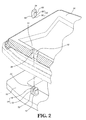
- the case assembly of the present invention comprises a first case 10, a second case 30 and a plurality of positioning members 50.
- the first case 10 includes a plurality of engaging members 12 thereon.
- Each engaging member 12 includes two clamping protrusions 14 which are located apart from each other.
- Each clamping protrusion 14 includes a supporting portion 16 and a protruding portion 18 which extends laterally from the supporting portion 16.
- a space 20 is defined between the two clamping protrusions 14.
- the protruding portions 18 of the clamping protrusions 14 define an opening of the space 20.
- the clamping protrusions 14 are made of flexible material and extend from the first case 10.
- each of the clamping protrusions 14 has a protrusion 22 which is located close to the opening of the space 20 corresponding thereto.
- the second case 30 includes a plurality of ports 32 defined therethrough which are located corresponding to the engaging members 12.
- the width of each of the ports 32 in the second case 30 is larger than the width between two respective outsides of the two protruding portions 18 of the clamping protrusions 14.
- Each port 32 has a shoulder 36 defined in an inside 34 thereof. The shoulder 36 is located corresponding to the protruding portions 18 of the clamping protrusions 14.
- the plurality of positioning members 50 are cooperated with the engaging members 12 of the first case 10.
- Each positioning member 50 has an insertion portion 52 and a head 54 which is located opposite to the insertion portion 52.
- the insertion portion 52 of each of the positioning members 50 includes a straight portion 56 and a gradually-narrowed portion 58 which extends from the straight portion 56.
- the gradually-narrowed portion 58 is located corresponding to the space 20 between the two clamping protrusions 14 corresponding thereto.
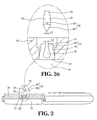
- the minimized width L1 of the gradually-narrowed portion 58 is smaller than the transverse width L2 of the opening of the space 20, as shown in Fig. 3a .
- the straight portion 56 of the insertion portion 52 includes a recess 60 which is located corresponding to the protrusion 22 of the clamping protrusion 14. The protrusions 22 of the clamping protrusion 14 are engaged with the recesses 60 when the positioning member 50 is inserted into the space 20.
- the two clamping protrusions 14 are inclined an angle toward each other such that the transverse width L2 of the opening of the space 20 is smaller than the width L3 of the straight portion 56 of the insertion portion 52, as shown in Fig. 3a .
- the first and second cases 10, 30 are easily assembled and an interior space is defined between the first and second cases 10, 30 so as to accommodate electronic parts such as communication modules.
- first and second cases 10, 30 When disassembling the first and second cases 10, 30, because the length of the positioning member 50 is longer than the depth of the space 20, so that the head 54 of the positioning member 50 is exposed outside the space 20 and the user can pull the head 54 away from the space 20 to remove the positioning member 50.
- the clamping protrusions 14 then bounce toward each other and the protruding portions 18 are disengaged from the shoulder 36.
- the first and second cases 10, 30 are separated from each other.
Landscapes
- Engineering & Computer Science (AREA)
- General Engineering & Computer Science (AREA)
- Signal Processing (AREA)
- Mechanical Engineering (AREA)
- Casings For Electric Apparatus (AREA)
- Connection Of Plates (AREA)
Applications Claiming Priority (1)
| Application Number | Priority Date | Filing Date | Title |
|---|---|---|---|
| TW098104567A TWI392804B (zh) | 2009-02-12 | 2009-02-12 | 電子裝置之殼體組裝構造 |
Publications (2)
| Publication Number | Publication Date |
|---|---|
| EP2219349A2 true EP2219349A2 (de) | 2010-08-18 |
| EP2219349A3 EP2219349A3 (de) | 2011-12-28 |
Family
ID=42138962
Family Applications (1)
| Application Number | Title | Priority Date | Filing Date |
|---|---|---|---|
| EP10152621A Withdrawn EP2219349A3 (de) | 2009-02-12 | 2010-02-04 | Gehäuseanordnung für eine elektronische Anwendung |
Country Status (4)
| Country | Link |
|---|---|
| US (1) | US8477930B2 (de) |
| EP (1) | EP2219349A3 (de) |
| JP (1) | JP3158898U (de) |
| TW (1) | TWI392804B (de) |
Families Citing this family (4)
| Publication number | Priority date | Publication date | Assignee | Title |
|---|---|---|---|---|
| US8845040B2 (en) * | 2009-08-25 | 2014-09-30 | Wistron Corporation | Housing for an electronic device |
| TWI366754B (en) * | 2009-08-25 | 2012-06-21 | Wistron Corp | Device housing for an electronic device |
| US8264837B2 (en) * | 2010-04-19 | 2012-09-11 | Apple Inc. | Systems and methods for cover assembly retention of a portable electronic device |
| JP7262616B2 (ja) * | 2019-12-12 | 2023-04-21 | 三菱電機株式会社 | 電子機器筐体 |
Citations (1)
| Publication number | Priority date | Publication date | Assignee | Title |
|---|---|---|---|---|
| US7092520B2 (en) | 1996-02-28 | 2006-08-15 | Nokia Corporation | Radiotelephone |
Family Cites Families (15)
| Publication number | Priority date | Publication date | Assignee | Title |
|---|---|---|---|---|
| US6347218B1 (en) * | 1996-02-28 | 2002-02-12 | Nokia Mobile Phones Limited | Electronic device with housing supplement |
| GB9821124D0 (en) * | 1998-09-29 | 1998-11-25 | Nokia Mobile Phones Ltd | Back cover for a mobile phone |
| SE515918C2 (sv) * | 1999-03-15 | 2001-10-29 | Ericsson Telefon Ab L M | Utbytbar panel hos en mobilradiostation, främre del för ett hus hos en mobilradiostation, mobilradiostation samt sätt för att bortagbart fästa den utbytbara panelen vid en mobilradiostation |
| US20020085709A1 (en) * | 2001-01-02 | 2002-07-04 | Gimmy Hsu | Cover for portable phone |
| US20020159586A1 (en) * | 2001-04-26 | 2002-10-31 | Tsan-Wen Chiou | Panel protective structure of a mobile telephone |
| DE10135934B4 (de) * | 2001-07-24 | 2005-10-06 | Siemens Ag | Verbindungssystem |
| US20030095656A1 (en) * | 2001-11-20 | 2003-05-22 | Sommer Henry David | Rugged design and method for housing an electronic device |
| TW544029U (en) * | 2002-05-10 | 2003-07-21 | Benq Corp | Mobile phone with exchangeable key module |
| TW570429U (en) * | 2002-06-21 | 2004-01-01 | Quanta Comp Inc | Mobile phone with a replaceable housing |
| TWM265866U (en) * | 2004-02-20 | 2005-05-21 | Fih Co Ltd | Replaceable panel for portable electronic device |
| TWM258507U (en) * | 2004-06-02 | 2005-03-01 | Fih Co Ltd | The replaceable panel for portable electronic device |
| TW200802450A (en) * | 2006-06-02 | 2008-01-01 | Altek Corp | Button assembly |
| EP1873869B1 (de) * | 2006-06-28 | 2013-07-10 | Weidmüller Interface GmbH & Co. KG | Elektrisches Modul |
| JP4584210B2 (ja) * | 2006-08-25 | 2010-11-17 | 京セラ株式会社 | 電子機器 |
| US8088507B2 (en) * | 2008-04-25 | 2012-01-03 | Universal Scientific Industrial (Shanghai) Co., Ltd. | Portable electronic device having secured battery |
-
2009
- 2009-02-12 TW TW098104567A patent/TWI392804B/zh active
-
2010
- 2010-02-03 US US12/699,372 patent/US8477930B2/en not_active Expired - Fee Related
- 2010-02-04 EP EP10152621A patent/EP2219349A3/de not_active Withdrawn
- 2010-02-08 JP JP2010000717U patent/JP3158898U/ja not_active Expired - Lifetime
Patent Citations (1)
| Publication number | Priority date | Publication date | Assignee | Title |
|---|---|---|---|---|
| US7092520B2 (en) | 1996-02-28 | 2006-08-15 | Nokia Corporation | Radiotelephone |
Also Published As
| Publication number | Publication date |
|---|---|
| TW201030246A (en) | 2010-08-16 |
| EP2219349A3 (de) | 2011-12-28 |
| US8477930B2 (en) | 2013-07-02 |
| JP3158898U (ja) | 2010-04-22 |
| US20100201235A1 (en) | 2010-08-12 |
| TWI392804B (zh) | 2013-04-11 |
Similar Documents
| Publication | Publication Date | Title |
|---|---|---|
| US20120251226A1 (en) | Deformable connection mechanism for connecting two shells | |
| US10642374B2 (en) | Keyboard/keyboard enclosure | |
| EP2219349A2 (de) | Gehäuseanordnung für eine elektronische Anwendung | |
| US12019810B2 (en) | Keyboard assembly | |
| EP2180668A1 (de) | Gehäuseanwendung für tragbare elektronische Vorrichtung | |
| US7656658B2 (en) | Mounting apparatus for data storage device | |
| US20090237888A1 (en) | Electrical assembly and fastening assembly thereof | |
| US8929058B2 (en) | Fastening device, housing, and electronic device | |
| EP3070399B1 (de) | Vorrichtung zur sicherung einer led-lichtquelle an einer kühlkörperoberfläche | |
| US20100052485A1 (en) | Fastening Device and a Computer Case Having the Fastening Device | |
| JP2011095691A (ja) | 眼鏡用のヒンジ機構 | |
| US20090004014A1 (en) | Fast-positioning device for assembling blade brackets to a motor housing of a ceiling fan | |
| US20120153784A1 (en) | Electronic device chassis | |
| US9016965B1 (en) | Keyboard/keyboard enclosure | |
| US20080036338A1 (en) | Block-shape container which can be assembled into and disassembled from a computer casing | |
| US20060076348A1 (en) | Electrical outlet box having attachable walls | |
| US7874627B2 (en) | Assembly for connecting plates | |
| JP2009068671A (ja) | ヒンジ構造及び折り畳み型電子機器 | |
| JP2016206629A (ja) | 表示装置 | |
| EP4212065B1 (de) | Modulare struktur mit einpressanordnung | |
| US7742613B2 (en) | Connecting means for housings of hearing devices | |
| US20130169123A1 (en) | Enclosure assembly | |
| US20140312190A1 (en) | Mounting structure for power supply | |
| EP2924822A1 (de) | Modulares Gehäuse für elektrische und elektronische Ausrüstungen | |
| CN101815410B (zh) | 电子装置的壳体组装构造 |
Legal Events
| Date | Code | Title | Description |
|---|---|---|---|
| PUAI | Public reference made under article 153(3) epc to a published international application that has entered the european phase |
Free format text: ORIGINAL CODE: 0009012 |
|
| AK | Designated contracting states |
Kind code of ref document: A2 Designated state(s): AT BE BG CH CY CZ DE DK EE ES FI FR GB GR HR HU IE IS IT LI LT LU LV MC MK MT NL NO PL PT RO SE SI SK SM TR |
|
| AX | Request for extension of the european patent |
Extension state: AL BA RS |
|
| PUAL | Search report despatched |
Free format text: ORIGINAL CODE: 0009013 |
|
| AK | Designated contracting states |
Kind code of ref document: A3 Designated state(s): AT BE BG CH CY CZ DE DK EE ES FI FR GB GR HR HU IE IS IT LI LT LU LV MC MK MT NL NO PL PT RO SE SI SK SM TR |
|
| AX | Request for extension of the european patent |
Extension state: AL BA RS |
|
| RIC1 | Information provided on ipc code assigned before grant |
Ipc: H05K 5/03 20060101ALI20111124BHEP Ipc: F16B 19/02 20060101ALI20111124BHEP Ipc: F16B 5/06 20060101ALI20111124BHEP Ipc: H04M 1/02 20060101AFI20111124BHEP |
|
| STAA | Information on the status of an ep patent application or granted ep patent |
Free format text: STATUS: THE APPLICATION IS DEEMED TO BE WITHDRAWN |
|
| 18D | Application deemed to be withdrawn |
Effective date: 20120629 |