EP2219281A2 - Circuit et procédé pour équilibrage de cellules - Google Patents
Circuit et procédé pour équilibrage de cellules Download PDFInfo
- Publication number
- EP2219281A2 EP2219281A2 EP10153247A EP10153247A EP2219281A2 EP 2219281 A2 EP2219281 A2 EP 2219281A2 EP 10153247 A EP10153247 A EP 10153247A EP 10153247 A EP10153247 A EP 10153247A EP 2219281 A2 EP2219281 A2 EP 2219281A2
- Authority
- EP
- European Patent Office
- Prior art keywords
- cell
- shunt path
- shunt
- coupled
- cells
- Prior art date
- Legal status (The legal status is an assumption and is not a legal conclusion. Google has not performed a legal analysis and makes no representation as to the accuracy of the status listed.)
- Withdrawn
Links
Images


Classifications
-
- H—ELECTRICITY
- H02—GENERATION; CONVERSION OR DISTRIBUTION OF ELECTRIC POWER
- H02J—CIRCUIT ARRANGEMENTS OR SYSTEMS FOR SUPPLYING OR DISTRIBUTING ELECTRIC POWER; SYSTEMS FOR STORING ELECTRIC ENERGY
- H02J7/00—Circuit arrangements for charging or depolarising batteries or for supplying loads from batteries
- H02J7/0013—Circuit arrangements for charging or depolarising batteries or for supplying loads from batteries acting upon several batteries simultaneously or sequentially
- H02J7/0014—Circuits for equalisation of charge between batteries
- H02J7/0016—Circuits for equalisation of charge between batteries using shunting, discharge or bypass circuits
-
- Y—GENERAL TAGGING OF NEW TECHNOLOGICAL DEVELOPMENTS; GENERAL TAGGING OF CROSS-SECTIONAL TECHNOLOGIES SPANNING OVER SEVERAL SECTIONS OF THE IPC; TECHNICAL SUBJECTS COVERED BY FORMER USPC CROSS-REFERENCE ART COLLECTIONS [XRACs] AND DIGESTS
- Y02—TECHNOLOGIES OR APPLICATIONS FOR MITIGATION OR ADAPTATION AGAINST CLIMATE CHANGE
- Y02T—CLIMATE CHANGE MITIGATION TECHNOLOGIES RELATED TO TRANSPORTATION
- Y02T10/00—Road transport of goods or passengers
- Y02T10/60—Other road transportation technologies with climate change mitigation effect
- Y02T10/70—Energy storage systems for electromobility, e.g. batteries
Definitions
- a typical Lithium-Ion (Li-Ion) battery pack usually includes a group of battery cells connected in series. Charging and discharging the battery pack through normal operation overtime may result in cell-to-cell variations in cell voltages. When one or more cells in a series string charge faster or slower than the others, an unbalanced condition may occur.
- FIG. 1 illustrates a conventional cell balancing circuit.
- Multiple cells connected in series include a first cell 102 and a second cell 103.
- the positive terminal (anode) of the cell 102 is coupled to a controller 110 at a terminal BAT1 through a resistor 108.
- the negative terminal (cathode) of the cell 102 is coupled to the controller 110 at a terminal BAT0 through a resistor 106.
- An external shunt path (bypass path) is parallel-connected with the cell 102.
- the shunt path can include a current limiting resistor 101 and a bleeding control switch 104 connected in series with the current limiting resistor 101.
- the bleeding control switch 104 is controlled by the controller 110 via a dedicated pin CB1.
- the positive terminal of the cell 103 is coupled to the controller 110 at the terminal BAT2 through a resistor 112.
- the negative terminal of the cell 103 is coupled to the controller 110 at the terminal BAT1 through the resistor 108.
- An external shunt path is parallel-connected with the cell 103.
- the shunt path can include a current limiting resistor 114 and a bleeding control switch 116 connected in series with the current limiting resistor 114.
- the bleeding control switch 116 is controlled by the controller 110 via a dedicated pin CB2.
- the controller 110 may turn on the switch 104 to enable a shunt current to flow through the external shunt path, thus charging of the cell 102 can be slowed down and the cell voltages can be balanced in the battery pack.
- an extra pin e.g., CB1 for cell 102, CB2 for cell 103 to control a corresponding bleeding control switch, which can increase the cost.
- FIG. 2 shows another conventional cell balancing circuit. Elements labeled the same as in FIG. 1 have similar functions.
- an internal switch 212 is coupled between the terminal BAT1 and the terminal BAT0.
- An internal switch 216 is coupled between the terminal BAT2 and the terminal BAT1. Internal switch 212 and internal switch 216 are under control of an internal switch control unit 214 which is also located in the controller 210.
- the internal switch 212 in order to conduct the shunt path of the cell 102, the internal switch 212 needs to be turned on in order to enable a current I2 flowing from the positive terminal of the cell 102 through the resistor 108, terminal BAT1 and internal switch 212 to the terminal BAT0, then through the resistor 106 to the negative terminal of the cell 102.
- the internal switch 216 In order to conduct the shunt path of the cell 103, the internal switch 216 needs to be turned on in order to enable a current 13 flowing from a positive terminal of the cell 103, through the resistor 112 to the terminal BAT2 and internal switch 216 to the terminal BAT1, then through the resistor 108 to the negative terminal of the cell 103.
- a cell balancing circuit used for balancing a plurality of cells including a first cell and a second cell adjacent to the first cell.
- the cell balancing circuit includes a first shunt path coupled to the first cell in parallel for enabling a shunt current of the first cell, a second shunt path coupled to the second cell in parallel for enabling a shunt current of the second cell.
- the cell balancing circuit further includes a controller which is coupled to the first shunt path and the second shunt path. The controller is operable for alternately conducting the first shunt path and the second shunt path if the first cell and the second cell are unbalanced.
- said controller may be operable for conducting said first shunt path in a first series of discrete time slots, and for conducting said second shunt path in a second series of discrete time slots, wherein said first series of discrete time slots and said second series of discrete time slots are mutually exclusive. Further, said controller may be operable for conducting said first shunt path and cutting off said second shunt path in a first time slot, and for cutting off said first shunt path and conducting said second shunt path in a second time slot.
- said controller may further comprise a first switch coupled to said first shunt path for controlling a conductance status of said first shunt path by enabling a first control current flowing through said first switch; a second switch coupled to said second shunt path for controlling a conductance status of said second shunt path by enabling a second control current flowing through said second switch, wherein said controller is operable for alternately turning on said first internal switch and said second switch.
- said cell balancing circuit may further comprise a first resistor coupled between said first shunt path and said first internal switch, wherein said first control current flows through said first resistor to produce a voltage drop on said first resistor, and wherein a conductance status of said first shunt path is determined by said voltage drop.
- a battery management system comprises a charger for charging a plurality of cells comprising a first cell and a second cell adjacent to said first cell; a monitoring circuit coupled to said cells for monitoring said cells and for detecting an unbalanced condition of said cells; and a cell balancing circuit coupled to said monitoring circuit for balancing said cells, said cell balancing circuit comprising: a first shunt path coupled to said first cell in parallel for enabling a shunt current of said first cell; a second shunt path coupled to said second cell in parallel for enabling a shunt current of said second cell; and a controller coupled to said first shunt path and said second shunt path and operable for alternately conducting said first shunt path and said second shunt path if said first cell and said second cell are unbalanced.
- said controller may be operable for conducting said first shunt path in a first series of discrete time slots, and for conducting said second shunt path in a second series of discrete time slots, wherein said first series of discrete time slots and said second series of discrete time slots are mutually exclusive. Further said controller may be operable for conducting said first shunt path and cutting off said second shunt path in a first time slot, and for cutting off said first shunt path and conducting said second shunt path in a second time slot.
- said controller may further comprise a first switch coupled to said first shunt path for controlling a conductance status of said first shunt path by enabling a first control current flowing from a positive terminal of said first cell through said first switch to a negative terminal of said first cell; a second switch coupled to said second shunt path for controlling a conductance status of said second shunt path by enabling a second control current flowing from a positive terminal of said second cell through said second switch to a negative terminal of said second cell, wherein said controller is operable for alternately turning on said first switch and said second switch.
- Said battery management system may further comprise a first resistor coupled between said first shunt path and said first internal switch, wherein said first control current flows through said first resistorto produce a voltage drop on said first resistor, and wherein a conductance status of said first shunt path is determined by said voltage drop.
- said first shunt path may comprise a bleeding control switch, and wherein a conductance status of said bleeding control switch is determined by said voltage drop.
- a method for balancing a plurality of cells comprises: dividing said plurality of cells into a first group and a second group, wherein each cell from said first group is adjacent to at least one cell from said second group; monitoring an unbalanced condition of said plurality of cells; and alternately enabling shunt current for a first plurality of unbalanced cells from said first group and shunt current for a second plurality of unbalanced cells from said second group.
- said method further may comprise balancing said first plurality of unbalanced cells from said first group in a first series of discrete time slots; and balancing said second plurality of unbalanced cells from said second group in a second series of discrete time slots, wherein said first series of discrete time slots and said second series of discrete time slots are mutually exclusive.
- Said method may further comprise conducting a plurality of shunt paths respectively coupled to said first plurality of unbalanced cells from said first group in a first series of discrete time slots; and conducting a plurality of shunt paths respectively coupled to said second plurality of unbalanced cells from said second group in a second series of discrete time slots, wherein said first series of discrete time slots and said second series of discrete time slots are mutually exclusive.
- Said method may further comprise alternately enabling a first control current corresponding to a first cell and a second control current corresponding to a second cell; conducting a first shunt path coupled to said first cell in response to said first control current; and conducting a second shunt path coupled to said second cell in response to said second control current.
- Said method may further comprise producing a voltage drop on a resistor coupled to said first shunt path by said first control current, wherein said first control current flows through said resistor.
- Said method may further comprise turning on a bleeding control switch in said first shunt path in response to said voltage drop to conduct said first shunt path.
- Said method may further comprise determining a cell is unbalanced if a voltage of said cell is greater than a predetermined threshold.
- Said method may further comprise determining a cell is unbalanced if a voltage difference between a first cell voltage of said cell and a second cell voltage of another cell is greater than a predetermined threshold.
- FIG. 1 illustrates a conventional cell balancing circuit using a dedicated pin to enable or disable a shunt path.
- FIG. 2 illustrates another conventional cell balancing circuit with a bleeding control switch controlled by an internal switch.
- Fig. 3 illustrates an electrical system, in accordance with one embodiment of the present invention.
- FIG. 4 illustrates a cell balancing circuit, in accordance with one embodiment of the present invention.
- FIG. 5 illustrates a cell balancing circuit, in accordance with one embodiment of the present invention.
- FIG. 6 illustrates a cell balancing circuit for balancing a group of cells, in accordance with one embodiment of the present invention.
- FIG. 7 illustrates a cell balancing circuit for balancing a group of cells, in accordance with one embodiment of the present invention.
- FIG. 8 illustrates a flowchart of a method for balancing a cell, in accordance with one embodiment of the present invention.
- FIG. 9 illustrates a cell balancing circuit, in accordance with one embodiment of the present invention.
- FIG. 10 illustrates a time multiplex algorithm used by the controller in FIG. 9 .
- FIG. 11 illustrates a battery management system, in accordance with one embodiment of the present invention.
- FIG. 12 illustrates a flowchart of a method for balancing a plurality of cells, in accordance with one embodiment of the present invention.
- Embodiments described herein may be discussed in the general context of computer-executable instructions residing on some form of computer-usable medium, such as program modules, executed by one or more computers or other devices.
- program modules include routines, programs, objects, components, data structures, etc., that perform particular tasks or implement particular abstract data types.
- the functionality of the program modules may be combined or distributed as desired in various embodiments.
- Computer-usable media may comprise computer storage media and communication media.
- Computer storage media includes volatile and nonvolatile, removable and non-removable media implemented in any method or technology for storage of information such as computer-readable instructions, data structures, program modules or other data.
- Computer storage media includes, but is not limited to, random access memory (RAM), read only memory (ROM), electrically erasable programmable ROM (EEPROM), flash memory or other memory technology, compact disk ROM (CD-ROM), digital versatile disks (DVDs) or other optical storage, magnetic cassettes, magnetic tape, magnetic disk storage or other magnetic storage devices, or any other medium that can be used to store the desired information.
- Communication media can embody computer-readable instructions, data structures, program modules or other data in a modulated data signal such as a carrier wave or other transport mechanism and includes any information delivery media.
- modulated data signal means a signal that has one or more of its characteristics set or changed in such a manner as to encode information in the signal.
- communication media includes wired media such as a wired network or direct-wired connection, and wireless media such as acoustic, radio frequency (RF), infrared and other wireless media. Combinations of any of the above should also be included within the scope of computer-readable media.
- FIG. 3 illustrates an electrical system 300 including a functional module 302 and a battery pack 304.
- the battery pack 304 includes a group of battery cells.
- the functional module 302 is powered by the battery pack 304 and can perform one or more functions.
- the electrical system 300 can include, but is not limited to, a computer system, a vehicle, an electrical bike, an uninterruptible power supply, etc.
- the functional module 302 includes a central processing unit (CPU) of a computer system.
- the functional module 302 includes a vehicle motor of a vehicle.
- a battery cell balancing circuit for the battery pack 304, which reduces pin numbers and can be operable even if a battery cell voltage is relatively low.
- the cell balancing circuit uses a current regulator to control a shunt path of a battery cell, in one embodiment.
- a bleeding control switch for conducting a shunt path of a battery cell can have various types and is not limited to a switch with a relatively low threshold voltage (e.g., 1 V).
- the battery cell balancing circuit is able to balance multiple cells simultaneously, e.g., to balance neighboring cells simultaneously.
- FIG. 4 illustrates a cell balancing circuit 400, in accordance with one embodiment of the present invention.
- the balancing circuit 400 in FIG. 4 utilizes a constant current regulator, e.g., an internal current sink 414, to control a conductance status of a shunt path of a cell cell-1, in one embodiment.
- the current regulator 414 is coupled to the shunt path for producing a current to control a conductance status of the shunt path.
- the shunt path is conducted (turned on) in response to the current produced by the current regulator 414, in one embodiment.
- the positive terminal (anode) of cell-1 in a battery pack is coupled to a controller 410 at the terminal BAT1 through a first resistor 408.
- the negative terminal (cathode) of cell-1 is coupled to the controller 410 at the terminal BAT0 through a second resistor 406.
- a shunt path is parallel-connected with cell-1 for enabling a shunt current of cell-1.
- the shunt path includes a bleeding (balancing) control switch 404 and a current limiting resistor 401 coupled in series.
- the bleeding control switch 404 can be a P channel metal oxide semiconductor field effect transistor (PMOSFET).
- the bleeding control switch 404 can conduct the shunt path in response to the current produced by the current regulator 414.
- the resistor 408 is coupled between the shunt path and the current sink 414.
- a conductance status of the bleeding control switch 404 is determined by its gate-to-source voltage Vgs, which is substantially equal to a voltage drop on the resistor 408, in the example of FIG. 4 .
- a controller 410 can be used to control a charging and/or discharging of the battery pack, and can be used to perform various protection functions (e.g., over-voltage protection, over-current protection, under-voltage protection, cell balancing) for the battery pack.
- the controller 410 can be integrated in the battery pack.
- the controller 410 can include a current regulator shown as a current sink 414 coupled between the terminal BAT1 and ground.
- the current sink 414 is operable for providing a sink current flowing from the positive terminal of cell-1 through the resistor 408 to ground and for controlling a conductance status of the shunt path.
- the current sink 414 sinks current from the positive terminal of cell-1.
- the sink current flows though the resistor 408, thereby producing a voltage drop on the resistor 408.
- the conductance status of the shunt path can be determined by the voltage drop across the resistor 408.
- the controller 410 may further include a current sink control unit 412 which is operable for controlling (e.g., enabling/disabling) the current sink 414.
- the current sink control unit 412 monitors cell-1 and enables the current sink 414 if cell-1 is unbalanced.
- cell-1 is unbalanced if a voltage of cell-1 is greater than a predetermined threshold.
- cell-1 is unbalanced if a difference between the voltage of cell-1 and a voltage of another cell (not shown in FIG. 4 for purposes of brevity and clarity) in the same battery pack is greater than a predetermined threshold.
- the shunt path of cell-1 can be built inside the controller 410.
- a resistance of the resistor 408 is 1 K ⁇
- the sink current provided by the current sink 414 is 3mA
- the threshold voltage of the bleeding control switch 404 is -1V.
- the cell balancing circuit in the present disclosure is not limited to such specific values.
- the current sink 414 can be enabled by the current sink control unit 412 to provide a sink current, e.g., 3mA, flowing from the positive terminal of cell-1 through the resistor 408 to ground.
- a sink current e.g. 3mA
- the voltage drop on the resistor 408 is 3V. Therefore, the gate-to-source voltage Vgs of the bleeding control switch 404 is -3V and the bleeding control switch 404 is turned on, in one embodiment. Once the bleeding control switch 404 is turned on, the corresponding shunt path is conducted (turned on).
- a shunt current (balancing current) can flow through the shunt path, thus balancing cell-1 with other cells.
- a shunt current balancing current
- part of the charging current of cell-1 can be shunted away via the shunt path, thus charging of cell-1 can be slowed down, and the cell unbalance can be reduced/eliminated after balancing for a time period.
- Such time period can be determined by the current sink control unit 412, in one embodiment.
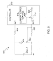
- FIG. 5 illustrates a cell balancing circuit 500, in accordance with one embodiment of the present invention. Elements labeled the same as in FIG. 4 have similar functions.
- the balancing circuit 500 in FIG. 5 utilizes a constant current regulator, e.g., an internal current source 514 to control a conductance status of a shunt path of a cell cell-1 in a battery pack, in one embodiment.
- the current regulator 514 is coupled to the shunt path for producing a current to control a conductance status of the shunt path.
- the shunt path is conducted (turned on) in response to the current produced by the current regulator 514, in one embodiment.
- a bleeding control switch 504 can be an N channel metal oxide semiconductor field effect transistor (NMOSFET).
- the bleeding control switch 504 can conduct the shunt path in response to the current produced by the current regulator 514.
- the positive terminal of cell-1 is coupled to a controller 510 at the terminal BAT1 through a first resistor 408.
- the negative terminal of cell-1 is coupled to the controller 510 at the terminal BAT0 through a second resistor 406.
- a conductance status of the bleeding control switch 504 is determined by its gate-to-source voltage Vgs, which is substantially equal to a voltage drop on the resistor 406, in the example of FIG. 5 .
- the controller 510 can be used to control a charging and/or discharging of the battery pack, and can be used to perform various protection functions (e.g., over-voltage protection, over-current protection, under-voltage protection, cell balancing) for the battery pack.
- the controller 510 can be integrated in the battery pack.
- the controller 510 can include a current regulator shown as a current source 514 which is coupled between the terminal BAT0 and a power supply Vcc 513.
- the current source 514 is operable for providing a source current flowing from the power supply 513 through the resistor 406 to the negative terminal of cell-1 and for controlling a conductance status of the shunt path.
- the current source 514 sources current to the negative terminal of cell-1.
- the source current flows through the resistor 406, thereby producing a voltage drop on the resistor 406.
- the conductance status of the shunt path can be determined by the voltage drop across the resistor 406.
- the controller 510 may further include a current source control unit 512 which is operable for controlling (e.g., enabling/disabling) the current source 514.
- the current source control unit 512 monitors cell-1 and enables the current source 514 if cell-1 is unbalanced.
- cell-1 is unbalanced if a voltage of cell-1 is greater than a predetermined threshold.
- cell-1 is unbalanced if a difference between the voltage of cell-1 and a voltage of another cell (not shown in FIG. 5 for purposes of brevity and clarity) in the same battery pack is greater than a predetermined threshold.
- the shunt path of cell-1 can be built inside the controller 510.
- a resistance of resistor 406 is 1K ⁇
- the source current provided by the current source 514 is 3mA
- the threshold voltage of the bleeding control switch 504 is 1V.
- the cell balancing circuit in the present disclosure is not limited to such specific values.
- the current source 514 can be enabled by the current source control unit 512 to provide a source current, e.g., 3mA, flowing from the power supply 513 to the negative terminal of cell-1 through the resistor 406. As such, the voltage drop across the resistor 406 is 3V. Therefore, the gate-to-source voltage Vgs of the bleeding control switch 504 is 3V and the bleeding control switch 504 is turned on, in one embodiment. Once the bleeding control switch 504 is turned on, the corresponding shunt path is conducted (turned on). Consequently, a shunt current (balancing current) can flow through the shunt path, thus balancing the cell voltages in the battery pack. A bleeding time period can be determined by the current source control unit 512, in one embodiment.
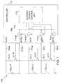
- FIG. 6 illustrates a cell balancing circuit for balancing a group of series-connected cells cell-1 ⁇ cell-N in a battery pack, in accordance with one embodiment of the present invention.
- Cell-1 ⁇ cell-N are coupled in series. Not all of the cells are shown in FIG. 6 for purposes of brevity and clarity.
- a plurality of shunt paths are coupled to the cells cell-1 ⁇ cell-N in parallel respectively, and each of the shunt paths is operable for enabling a shunt current of a corresponding cell.
- each shunt path can include a corresponding bleeding control switch Q1-1 ⁇ Q1-N and a corresponding resistor Rc-1 - Rc-N coupled in series.
- a conductance status of a shunt path is determined by a conductance status of a corresponding bleeding control switch Q1-1 ⁇ Q1-N.
- Each of the bleeding control switches Q1-1 ⁇ Q1-N can be a PMOSFET. Not all of the bleeding control switches and resistors are shown in FIG. 6 for purposes of brevity and clarity.
- a controller 610 is coupled to the plurality of cells cell-1 ⁇ cell-N for balancing the plurality of cells cell-1 ⁇ cell-N.
- the controller 610 comprises a plurality of current regulators, e.g., current sinks 614-1 - 614-N, which are coupled to the plurality of shunt paths respectively.
- Each of the current regulators 614-1 ⁇ 614-N is operable for producing a current flowing from a positive terminal of a corresponding cell to ground to control a conductance status of a corresponding shunt path, and the corresponding shunt path is conducted (turned on) in response to the current.
- Each bleeding control switch Q1-1 ⁇ Q1-N can conduct (turn on) a corresponding shunt path in response to the current produced from a corresponding current regulator 614-1 - 614-N.
- Terminals of the cells cell-1 ⁇ cell-N are coupled to the controller 610 at terminals BAT0 ⁇ BATN through resistors R0-0 ⁇ R0-N respectively.
- terminals BAT1 ⁇ BATN are coupled to ground through current sinks 614-1 ⁇ 614-N in the controller 610. Not all of the terminals, resistors, and current sinks are shown in FIG. 6 for purposes of brevity and clarity.
- each of the current regulators 614-1 ⁇ 614-N is operable for producing a current flowing through a corresponding resistor R0-1 ⁇ R0-N, which produces a voltage drop on the corresponding resistor R0-1 ⁇ R0-N.
- the conductance status of a corresponding bleeding control switch Q1-1 ⁇ Q1-N is determined by a voltage drop on the corresponding resistor R0-1 ⁇ R0-N, in one embodiment.
- the controller 610 can include a current sink control unit 612 which is operable for controlling current sinks 614-1 - 614-N.
- the current sink control unit 612 in the controller 610 enables a corresponding current sink 614-1 - 614-N if a corresponding cell cell-1 ⁇ cell-N is unbalanced.
- the current sinks 614-1 - 614-N can be enabled or disabled independently or simultaneously by the current sink control unit 612. Consequently, the balancing circuit can be operable for balancing the group of cells according to the state of each cell.
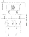
- FIG. 7 illustrates a cell balancing circuit for balancing a group of series-connected cells cell-1 ⁇ cell-N in a battery pack, in accordance with one embodiment of the present invention.
- Cell-1 ⁇ cell-N are coupled in series. Not all of the cells are shown in FIG. 7 for purposes of brevity and clarity.
- a plurality of shunt paths are coupled to the cells cell-1 ⁇ cell-N in parallel respectively, and each of the shunt paths is operable for enabling a shunt current of a corresponding cell.
- each shunt path can include a corresponding bleeding control switch Q1-1 ⁇ Q1-N and a resistor Rc-1 - Rc-N coupled in series.
- a conductance status of a shunt path is determined by a conductance status of a corresponding bleeding control switch Q1-1 ⁇ Q1-N.
- Each of the bleeding control switches Q1-1 ⁇ Q1-N can be an NMOSFET. Not all of the bleeding control switches and resistors are shown in FIG. 7 for purposes of brevity and clarity.
- a controller 710 is coupled to the plurality of cells cell-1 ⁇ cell-N for balancing the plurality of cells cell-1 ⁇ cell-N.
- the controller 710 comprises a plurality of current regulators, e.g., current sources 714-1 ⁇ 714-N, which are coupled to the plurality of shunt paths respectively.
- Each of the current regulators 714-1 ⁇ 714-N is operable for producing a current flowing from a power supply 718 to a negative terminal of a corresponding cell to control a conductance status of a corresponding shunt path, and the corresponding shunt path is conducted (turned on) in response to the current.
- Each bleeding control switch Q1-1 ⁇ Q1-N can conduct (turn on) a corresponding shunt path in response to the current produced from a corresponding current regulator 714-1 ⁇ 714-N.
- Terminals of the cells cell-1 ⁇ cell-N are coupled to the controller 710 at terminals BAT0 ⁇ BATN through resistors R0-0 ⁇ R0-N respectively.
- terminals BAT0 ⁇ BATN-1 are coupled to a power supply Vcc 718 through current sources 714-1 ⁇ 714-N in the controller 710. Not all of the terminals, resistors, and current sources are shown in FIG. 7 for purposes of brevity and clarity.
- each of the current regulators 714-1 ⁇ 714-N is operable for producing a current flowing through a corresponding resistor R0-0 ⁇ RO-N-1, which produces a voltage drop on the corresponding resistor R0-0 ⁇ RO-N-1.
- the conductance status of a corresponding bleeding control switch Q1-1 ⁇ Q1-N is determined by a voltage drop on the corresponding resistor R0-0 ⁇ RO-N-1, in one embodiment.
- the controller 710 can include a current source control unit 712 which is operable for controlling current source 714-1 ⁇ 714-N.
- the current source control unit 712 in the controller 710 enables a corresponding current source 714-1 ⁇ 714-N if a corresponding cell cell-1 ⁇ cell-N is unbalanced.
- the current source 714-1 ⁇ 714-N can be enabled or disabled independently or simultaneously by the current source control unit 712. Consequently, the balancing circuit can be operable for balancing a group of cells according to the state of each cell.
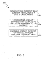
- FIG. 8 illustrates a flowchart 800 of a method for balancing a cell, in accordance with one embodiment of the present invention.
- FIG. 8 is described in combination with FIG. 4 and 5 .
- a current is generated by a current regulator, e.g., a current sink 414 or a current source 514, if a cell cell-1 is unbalanced.
- a voltage drop on a resistor 408/406 coupled between the shunt path and the current regulator can be produced (step not shown in FIG. 8 ).
- a bleeding control switch 404/504 can be turned on in response to the voltage drop on the resistor 408/406 (step not shown in FIG. 8 ). Therefore, in block 804, a shunt path coupled to cell-1 is conducted (turned on) in response to the current generated by the current regulator.
- a shunt current is enabled to flow through the shunt path.
- the PMOSFET and NMOSFET used in the above embodiments can be replaced by any other type of switches whose conductance status can be controlled by a voltage drop, without departing from the scope of the present disclosure.
- the resistor can also be replaced by any other type of components with resistance or impedance, across which a voltage drop can be developed due to a current flow, without departing from the scope of the present disclosure.
- the present invention intends to cover those equivalent embodiments.
- cell balancing circuits in the present invention can be applicable for different types of battery cells, because a conductance status of a bleeding control switches is not affected by a cell voltage.
- the present invention is further capable of simultaneously balancing neighboring cells.
- a current regulator generates currents with the same direction either flow into the controller (when current sinks are used as shown in FIG. 6 ) or flow out of the controller (when current sources are used as shown in FIG. 7 ). Therefore, there is no confliction of current direction. Consequently, multiple cells, no matter neighboring cells or non-neighboring cells, can be simultaneously balanced by a single controller, in one embodiment.
- the cell balancing circuits can be used in battery charging and battery discharging, stand-by conditions, in one embodiment.
- FIG. 9 illustrates a cell balancing circuit 900 for balancing a group of series-connected cells cell-1 ⁇ cell-N in a battery pack, in accordance with one embodiment of the present invention. Not all of the cells are shown in FIG. 9 for purposes of brevity and clarity.
- the balancing circuit 900 in the example of FIG. 9 includes a controller 910 which is operable for balancing cell-1 ⁇ cell-N using a time-multiplex algorithm to avoid a confliction of current direction that may occur in FIG. 2 .
- the cell balancing circuit 900 includes a plurality of shunt paths coupled to cell-1 ⁇ cell-N in parallel respectively. Each shunt path is operable for enabling a shunt current of a corresponding cell.
- each shunt path can include a corresponding bleeding control switch Q1-1 ⁇ Q1-N and a corresponding resistor Rc-1 - Rc-N coupled in series.
- the shunt path coupled to cell-1 includes a bleeding control switch Q1-1 and a resistor Rc-1. Not all of the bleeding control switches and resistors are shown in FIG. 9 for purposes of brevity and clarity.
- a conductance status of a shunt path can be determined by a conductance status of a corresponding bleeding control switch Q1-1 ⁇ Q1-N.
- each of the bleeding control switches Q1-1 ⁇ Q1-N can be a P channel metal oxide semiconductor field effect transistor (PMOSFET).
- a conductance status of a bleeding control switch Q1-1 ⁇ Q1-N is determined by its gate-to-source voltage Vgs, which is substantially equal to a voltage drop on a corresponding resistor R0-1 ⁇ R0-N.
- Terminals of cell-1 ⁇ cell-N are coupled to the controller 910 at terminals BAT0 ⁇ BATN through resistors R0-0 ⁇ R0-N respectively.
- the controller 910 includes a plurality of internal switches Q2-1 - Q2-N. Each of the internal switches Q2-1 - Q2-N is coupled between two corresponding terminals of the controller 910. For example, internal switch Q2-1 is coupled between terminals BAT0 and BAT1. Internal switch Q2-2 is coupled between terminals BAT1 and BAT2. Internal switch Q2-N is coupled between terminals BATN-1 and BATN. An on/off status of each of the internal switches Q2-1 - Q2-N can determine a conductance status of a corresponding shunt path. Not all of the internal switches are shown in FIG. 9 for purposes of brevity and clarity.
- the controller 910 can further include an internal switch control unit 912 for controlling the on/off status of each of the internal switches Q2-1 - Q2-N.
- a corresponding internal switch Q2-1 can be turned on (e.g., by the internal switch control unit 912) to enable a first control current flowing from a positive terminal of cell-1 through the internal switch Q2-1 to a negative terminal of cell-1.
- a voltage drop can be generated across the resistor R0-1, such that the bleeding control switch Q1-1 can be turned on in response to the voltage drop.
- the bleeding control switch Q1-1 is turned on, the corresponding shunt path coupled to cell-1 is conducted.
- a shunt current can flow through the shunt path, thus balancing cell-1 with the other cells. For example, during a battery charging phase, if a shunt current is enabled for the cell-1, part of the charging current of the cell-1 can be shunted away via the shunt path, thus charging of the cell-1 can be slowed down.
- a corresponding internal switch Q2-2 can be turned on (e.g., by the internal switch control unit 912) to enable a second control current flowing from a positive terminal of cell-2 through the internal switch Q2-2 to a negative terminal of cell-2.
- a voltage drop can be generated across the resistor R0-2, such that the bleeding control switch Q1-2 can be turned on in response to the voltage drop.
- cell-1 ⁇ cell-N can be divided into multiple groups, e.g., a first group and a second group, in one embodiment.
- the first group can include odd numbered cells cell-1, cell-3, cell-5, ...and cell-N-1.
- the second group can include even numbered cells cell-2, cell-4, cell-6, ...and cell-N.
- each cell from the first group is adjacent to at least one cell from the second group.
- each cell from the second group is adjacent to at least one cell from the first group.
- the controller 910 can alternately balance the unbalanced cells from the first group and the unbalanced cells from the second group. More specifically, the controller 910 can control the on/off status of the internal switches Q2-1 - Q2-N through the internal switch control unit 912 to conduct the shunt paths coupled to the unbalanced cells from the first group in a first series of discrete time slots, and to conduct the shunt paths coupled to the unbalanced cells from the second group in a second series of discrete time slots.
- the first series of discrete time slots and the second series of discrete time slots are mutually exclusive, in one embodiment.
- a confliction of the current direction of the control current that may occur in the cell balancing circuit in FIG. 2 can be avoided.
- the PMOSFET used in the above embodiments can be replaced by any other type of switches whose conductance status can be controlled by a voltage drop, without departing from the scope of the present disclosure.
- the resistor can also be replaced by any other type of components with resistance or impedance, across which a voltage drop can be developed due to a current flow, without departing from the scope of the present disclosure.
- the present invention intends to cover those equivalent embodiments.
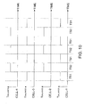
- FIG. 10 illustrates an example of the time multiplex algorithm used by the controller in FIG. 9 for alternately balancing the unbalanced cells from the first group and the unbalanced cells from the second group.
- FIG. 10 is described in combination with FIG. 9 .
- a first series of discrete time slots which include the time slots labeled as TS1 can be assigned to the first group
- a second series of discrete time slots which include the time slots labeled as TS2 can be assigned to the second group.
- the first series of discrete time slots and the second series of discrete time slots are mutually exclusive.
- the controller 910 selects the first group for balancing, and stops balancing the second group.
- the controller 910 can conduct the shunt paths coupled to cell-1 and cell-3 to balance cell-1 and cell-3, and cut off the shunt paths coupled to cell-2 and cell-4 to stop balancing cell-2 and cell-4 during time slots TS1.
- the controller 910 can turn on internal switches Q2-1 and Q2-3 so as to conduct the shunt paths coupled to cell-1 and cell-3 respectively.
- a control current can be enabled to flow from the positive terminal of cell-1 through the resistor R0-1, the internal switch Q2-1, and the resistor R0-0 to the negative terminal of cell-1.
- a voltage drop can be generated across the resistor R0-1.
- the bleeding control switch Q1-1 can be turned on in response to the voltage drop across the resistor R0-1, such that a shunt current can be enabled for cell-1.
- a control current can be enabled to flow from the positive terminal of cell-3 through the resistor R0-3, the internal switch Q2-3, and the resistor R0-2 to the negative terminal of cell-3.
- a voltage drop can be generated across the resistor R0-3.
- the bleeding control switch Q1-3 can be turned on in response to the voltage drop across the resistor R0-3, such that a shunt current can be enabled for cell-3.
- the controller 910 selects the second group for balancing, and stops balancing the first group.
- the controller 910 can conduct the shunt paths coupled to cell-2 and cell-4 to balance cell-2 and cell-4, and cut off the shunt paths coupled to cell-1 and cell-3 to stop balancing cell-1 and cell-3.
- the controller 910 can turn on internal switches Q2-2 and Q2-4 so as to conduct the shunt paths coupled to cell-2 and cell-4 respectively.
- a control current can be enabled to flow from the positive terminal of cell-2 through the resistor R0-2, the internal switch Q2-2, and the resistor R0-1 to the negative terminal of cell-2.
- a voltage drop can be generated across the resistor R0-2.
- the bleeding control switch Q1-2 can be turned on in response to the voltage drop across the resistor R0-2, such that a shunt current can be enabled for cell-2.
- a control current can be enabled to flow from the positive terminal of cell-4 through the resistor R0-4, the internal switch Q2-4, and the resistor R0-3 to the negative terminal of cell-4.
- a voltage drop can be generated across the resistor R0-4.
- the bleeding control switch Q1-4 can be turned on in response to the voltage drop across the resistor R0-4, such that a shunt current can be enabled for cell-4.
- the shunt currents of the adjacent cells can be enabled alternately.
- a confliction of the current direction can be avoided. For example, consider the control current flowing through the resistor R0-1. In time slots labeled as TS1, a control current flows from the positive terminal of cell-1 through the resistor R0-1 to the negative terminal of cell-1 (flows into the controller 910) to conduct the shunt path of cell-1. In time slots labeled as TS2, a control current flows from the positive terminal of cell-2 through the resistor R0-1 to the negative terminal of cell-2 (flows out of the controller 910) to conduct the shunt path of cell-2.
- the length of each time slot can be relatively short, such as 5 ms.
- the time multiplex algorithm described above can be used by various kinds of cell balancing circuits which can have different configurations and are not limited to the configuration as shown in the example of FIG. 9 .
- FIG. 11 illustrates a battery management system 1100, in accordance with one embodiment of the present invention. Elements labeled the same as in FIG. 9 have similar functions.
- the battery management system 1100 includes a charger 1102 for charging a plurality of cells cell-1 ⁇ cell-N in a battery pack 1106, a monitoring circuit 1104 for monitoring cells cell-1 ⁇ cell-N and detecting an unbalanced condition, and a controller 910 for balancing cell-1 ⁇ cell-N using the time-multiplex algorithm illustrated in FIG. 10 .
- Cell-1 ⁇ cell-N can be divided into a plurality of groups, e.g., a first group comprising odd numbered cells and a second group comprising even numbered cells.
- the controller 910 can further include an internal switch control unit 912 for controlling a plurality of internal switches Q2-1 ⁇ Q2-2 to conduct a plurality of shunt paths respectively coupled to cell-1 ⁇ cell-N.
- the monitoring circuit 1104 is implemented out of the controller 910. In another embodiment, the monitoring circuit 1104 can be built inside in the controller 910.
- the charger 1102 charges cell-1 ⁇ cell-N. Unbalanced conditions may occur during charging.
- the monitoring circuit 1104 monitors the status, e.g., cell voltages, of each cell and transmits the monitored information to the controller 910.
- a cell is unbalanced if a voltage of the cell is greater than a predetermined threshold. In an alternative embodiment, a cell is unbalanced if a difference between the voltage of the cell and a voltage of another cell in the same battery pack is greater than a predetermined threshold.
- the controller 910 can use the time-multiplex algorithm illustrated in FIG. 10 to alternately balance the unbalanced cells from the first group and the unbalanced cells from the second group.
- the controller 910 can conduct a corresponding shunt path to enable a shunt current.
- the controller 910 can turn on an internal switch, e.g., internal switch Q2-1 - Q2-N, to enable a control current flowing through a resistor, e.g., resistor R0-1 ⁇ R0-N, to generate a voltage drop across the resistor.
- a corresponding bleeding control switch, e.g., bleeding control switch Rc-1 - Rc-N, in the shunt path can be turned on in response to the voltage drop, such that the shunt path can be conducted.
- FIG. 12 illustrates a flowchart 1200 of a method for balancing a plurality of cells, in accordance with one embodiment of the present invention.
- FIG. 12 is described in combination with FIG. 10 and FIG. 11 .
- cell balancing during battery charging is illustrated.
- the cell balancing in the present invention can be used in many other operation phases such as battery discharging and battery stand-by phases.
- the charger 1102 starts to charge a plurality of cells cell-1 ⁇ cell-N. Unbalanced conditions may occur during charging.
- each cell is monitored, e.g., by a monitoring circuit 1104. The monitored information is transmitted to a controller 910.
- the controller 910 can determine if a cell is unbalanced with other cells. In one embodiment, a cell is unbalanced if a voltage of the cell is greater than a predetermined threshold. In another embodiment, a cell is unbalanced if a voltage difference between a first cell voltage of the cell and a second cell voltage of another cell is greater than a predetermined threshold.
- the flowchart 1200 goes back to block 1204 to continue monitoring each cell. If a cell, e.g., cell-i, needs to be balanced, the flowchart 1200 goes to block 1208 to determine whether cell-i belongs to a first group or to a second group.
- the controller 910 can balance the cell using the time multiplex algorithm illustrated in FIG. 10 based on a determination of whether cell-i belongs to the first group orto the second group.
- the flowchart 1200 goes to block 1210 and the balanced time Tbalance for cell-i is assigned with a first series of discrete time slots, such as the time slots labeled as TS1 in FIG. 10 .
- the flowchart 1200 goes to block 1212 and the balanced time Tbalance for cell-i is assigned with a second series of discrete time slots, such as the time slots labeled as TS2 in FIG. 10 .
- the first series of discrete time slots and the second series of discrete time slots are mutually exclusive.
- the flowchart 1200 goes to block 1214 to balance cell-i in the balanced time Tbalance.
- a shunt path coupled to cell-i is conducted to enable a shunt current flowing through the shunt path, in one embodiment.
- cell-i is monitored, e.g., by the monitoring circuit 1104 to determine if the balancing for cell-i is finished. If cell-i still needs balancing, the flowchart 1200 goes back to block 1204 to continue monitoring each cell. If cell-i is balanced with other cells, the flowchart 1200 goes to block 1218 to terminate the balancing of cell-i. Subsequently, the flowchart 1200 can go back to block 1204 to continue monitoring each cell.
- extra pins for controlling shunt paths are omitted, such that the cost can be reduced.
- the confliction of current direction can be avoided by using the time multiplex algorithm. Consequently, multiple cells can be balanced substantially at the same time by a single controller, in one embodiment.
- the cell balancing circuits can be used in battery charging, battery discharging or in stand-by conditions, in one embodiment.
Landscapes
- Engineering & Computer Science (AREA)
- Power Engineering (AREA)
- Charge And Discharge Circuits For Batteries Or The Like (AREA)
- Secondary Cells (AREA)
Applications Claiming Priority (1)
| Application Number | Priority Date | Filing Date | Title |
|---|---|---|---|
| US12/378,235 US20100033128A1 (en) | 2007-10-09 | 2009-02-11 | Circuit and method for cell balancing |
Publications (2)
| Publication Number | Publication Date |
|---|---|
| EP2219281A2 true EP2219281A2 (fr) | 2010-08-18 |
| EP2219281A3 EP2219281A3 (fr) | 2017-04-12 |
Family
ID=42200808
Family Applications (1)
| Application Number | Title | Priority Date | Filing Date |
|---|---|---|---|
| EP10153247.1A Withdrawn EP2219281A3 (fr) | 2009-02-11 | 2010-02-11 | Circuit et procédé pour équilibrage de cellules |
Country Status (5)
| Country | Link |
|---|---|
| US (1) | US20100033128A1 (fr) |
| EP (1) | EP2219281A3 (fr) |
| JP (1) | JP2010187534A (fr) |
| CN (1) | CN101800436B (fr) |
| TW (1) | TW201034338A (fr) |
Families Citing this family (26)
| Publication number | Priority date | Publication date | Assignee | Title |
|---|---|---|---|---|
| US8547064B2 (en) * | 2010-01-14 | 2013-10-01 | Texas Instruments Incorporated | Battery cell tab monitor |
| US8872478B2 (en) * | 2010-03-09 | 2014-10-28 | O2Micro Inc. | Circuit and method for balancing battery cells |
| US20120086401A1 (en) * | 2010-10-07 | 2012-04-12 | Intersil Americas Inc. | Cell balancing circuit for use in a multi-cell battery system |
| TWI420778B (zh) * | 2010-11-04 | 2013-12-21 | Chao Cheng Lu | 電池組並聯裝置 |
| US8089249B2 (en) * | 2010-11-08 | 2012-01-03 | O2Micro, Inc. | Battery management systems and methods |
| DE102010043912A1 (de) | 2010-11-15 | 2012-05-16 | Robert Bosch Gmbh | Verfahren zur Bestimmung des Ladezustands von Zellen einer Batterie, Batterie mit einem Modul zur Bestimmung des Ladezustands von Zellen der Batterie sowie ein Kraftfahrzeug mit einer entsprechenden Batterie |
| US8957624B2 (en) * | 2011-01-20 | 2015-02-17 | Valence Technology, Inc. | Rechargeable battery systems and rechargeable battery system operational methods |
| US8922167B2 (en) * | 2011-01-20 | 2014-12-30 | Valence Technology, Inc. | Rechargeable battery systems and rechargeable battery system operational methods |
| US9340122B2 (en) * | 2011-05-31 | 2016-05-17 | Hitachi Automotive Systems, Ltd. | Battery system monitoring apparatus |
| US9559529B1 (en) * | 2011-07-28 | 2017-01-31 | The United States Of America As Represented By The Administrator Of National Aeronautics And Space Administration | Modular battery controller |
| JP2013046433A (ja) * | 2011-08-22 | 2013-03-04 | Seiko Instruments Inc | セルバランス装置およびバッテリシステム |
| CN102340022B (zh) * | 2011-09-16 | 2014-11-05 | 奇瑞汽车股份有限公司 | 一种动力型电池及其制造方法 |
| CN103035959A (zh) * | 2011-10-09 | 2013-04-10 | 西胜国际股份有限公司 | 平衡电池系统分支电流的方法和平衡分支电流的电池系统 |
| CN103035869A (zh) * | 2011-10-09 | 2013-04-10 | 西胜国际股份有限公司 | 在组装电池系统中提升安全的方法和封包的电池系统 |
| KR20130091951A (ko) * | 2012-02-09 | 2013-08-20 | 삼성에스디아이 주식회사 | 배터리 시스템, 이의 제어 방법 및 이를 포함하는 에너지 저장 시스템 |
| EP2665120B1 (fr) * | 2012-05-14 | 2016-08-03 | Micro-Beam SA | Procédé et système d'équilibrage de cellules constitutives d'une batterie |
| US9362772B2 (en) | 2012-08-14 | 2016-06-07 | Texas Instruments Incorporated | System and method for balancing voltages |
| JP6107836B2 (ja) | 2015-01-07 | 2017-04-05 | トヨタ自動車株式会社 | 電池監視装置 |
| JP2018117438A (ja) * | 2017-01-17 | 2018-07-26 | 太陽誘電株式会社 | リチウムイオンキャパシタを備えた電源モジュール |
| CN107086632B (zh) * | 2017-05-26 | 2023-04-25 | 泉州华威国维电子科技有限公司 | 一种电池 |
| CN110015167B (zh) * | 2017-08-31 | 2021-09-03 | 比亚迪股份有限公司 | 电池均衡系统、车辆、电池均衡方法及存储介质 |
| CN108063473A (zh) * | 2017-12-15 | 2018-05-22 | 杰华特微电子(杭州)有限公司 | 电池均衡电路及控制方法 |
| WO2019189161A1 (fr) * | 2018-03-28 | 2019-10-03 | パナソニックIpマネジメント株式会社 | Circuit de décharge de dispositif de stockage d'énergie, système de stockage d'énergie et véhicule équipé de celui-ci |
| CN109842179A (zh) * | 2019-02-27 | 2019-06-04 | 杰华特微电子(杭州)有限公司 | 电池组检测电路及检测方法 |
| CN112737012B (zh) * | 2020-12-16 | 2023-03-24 | 上海摩芯半导体技术有限公司 | 充电电池组均衡控制电路及均衡控制方法 |
| CN117501577A (zh) * | 2022-05-31 | 2024-02-02 | 北京小米移动软件有限公司 | 电池均衡电路和电池均衡方法 |
Family Cites Families (14)
| Publication number | Priority date | Publication date | Assignee | Title |
|---|---|---|---|---|
| US5631534A (en) * | 1995-08-21 | 1997-05-20 | Delco Electronics Corp. | Bidirectional current pump for battery charge balancing |
| US6140800A (en) * | 1999-05-27 | 2000-10-31 | Peterson; William Anders | Autonomous battery equalization circuit |
| TW542470U (en) * | 2000-07-11 | 2003-07-11 | Ind Tech Res Inst | Battery voltage balancer |
| US6285161B1 (en) * | 2000-09-11 | 2001-09-04 | O2 Micro International Limited | Battery cell charging system having voltage threshold and bleeder current generating circuits |
| DE10134147A1 (de) * | 2001-07-13 | 2003-02-06 | Daimler Chrysler Ag | Vorrichtung für den Ladungsausgleich |
| CA2406500C (fr) * | 2001-10-01 | 2008-04-01 | Research In Motion Limited | Circuit de protection contre les surtensions pour circuit de charge |
| CN1512644A (zh) * | 2002-12-30 | 2004-07-14 | 广达电脑股份有限公司 | 充电式电位平衡装置 |
| JP4035777B2 (ja) * | 2003-02-10 | 2008-01-23 | 株式会社デンソー | 組電池の放電装置 |
| CN2790010Y (zh) * | 2005-03-25 | 2006-06-21 | 苏州星恒电源有限公司 | 锂充电电池充放电均衡电路的执行电路 |
| US7466104B2 (en) * | 2006-10-13 | 2008-12-16 | O2 Micro International Limited | System and method for balancing cells in a battery pack with selective bypass paths |
| DE102007023023A1 (de) * | 2007-05-16 | 2008-11-27 | Siemens Ag | Schaltungsanordnung und Verfahren zum Betreiben einer Energiespeicheranordnung |
| US20090079391A1 (en) * | 2007-09-25 | 2009-03-26 | O2Micro Inc. | Systems and methods for cell balancing |
| US7973514B2 (en) * | 2007-10-09 | 2011-07-05 | O2Micro, Inc. | Battery cell balancing systems using current regulators |
| CA2663334C (fr) * | 2008-04-18 | 2015-11-24 | Railpower Technologies Corp. | Systeme et methode d'egalisation dynamique de batteries, sans perte |
-
2009
- 2009-02-11 US US12/378,235 patent/US20100033128A1/en not_active Abandoned
-
2010
- 2010-01-21 CN CN2010100033628A patent/CN101800436B/zh active Active
- 2010-02-10 JP JP2010027845A patent/JP2010187534A/ja active Pending
- 2010-02-11 TW TW099104351A patent/TW201034338A/zh unknown
- 2010-02-11 EP EP10153247.1A patent/EP2219281A3/fr not_active Withdrawn
Non-Patent Citations (1)
| Title |
|---|
| None |
Also Published As
| Publication number | Publication date |
|---|---|
| TW201034338A (en) | 2010-09-16 |
| CN101800436A (zh) | 2010-08-11 |
| JP2010187534A (ja) | 2010-08-26 |
| EP2219281A3 (fr) | 2017-04-12 |
| US20100033128A1 (en) | 2010-02-11 |
| CN101800436B (zh) | 2013-09-25 |
Similar Documents
| Publication | Publication Date | Title |
|---|---|---|
| EP2219281A2 (fr) | Circuit et procédé pour équilibrage de cellules | |
| US7973514B2 (en) | Battery cell balancing systems using current regulators | |
| US11349144B2 (en) | Rechargeable multi-cell battery | |
| KR101975395B1 (ko) | 배터리 팩 및 이의 제어 방법 | |
| KR101182890B1 (ko) | 배터리 팩 충전 제어 시스템 | |
| US10958083B2 (en) | Battery pack with reduced voltage variance | |
| US20060097700A1 (en) | Method and system for cell equalization with charging sources and shunt regulators | |
| US20130293006A1 (en) | Battery balancing system and battery balancing method using the same | |
| JP7101484B2 (ja) | バッテリへの電力供給の制御 | |
| KR20190047601A (ko) | 배터리 밸런싱을 위한 장치 및 그것을 포함하는 배터리팩 | |
| KR20130046234A (ko) | 배터리 팩 및 이의 제어 방법 | |
| JP2012034529A (ja) | 二次電池パック接続制御方法、蓄電システム、および二次電池パック | |
| EP2593802A1 (fr) | Appareil de protection à semi-conducteurs pour une batterie assemblée, bloc-batterie comprenant l'appareil de protection à semi-conducteurs, ainsi que dispositif électronique | |
| JP2008043009A (ja) | 電池パックおよび制御方法 | |
| KR20170071949A (ko) | 배터리 팩 및 이를 포함하는 배터리 시스템 | |
| US20180152030A1 (en) | Dual cell protection ic and battery module including same | |
| KR20110134751A (ko) | 배터리 팩 및 이의 제어 방법 | |
| US9935472B2 (en) | Battery pack | |
| KR101858321B1 (ko) | 셀 밸런싱 회로의 고장 진단 장치 및 방법 | |
| US20150035490A1 (en) | Battery management system and method | |
| KR20180035080A (ko) | 배터리 셀 밸런싱 회로 | |
| JP2009201345A (ja) | 電流レギュレータを使用した電池セルバランシングシステム | |
| CN115800418B (zh) | 电池控制方法、储能系统、装置、计算机设备和存储介质 | |
| JP2022508101A (ja) | バッテリ管理システム | |
| KR102347920B1 (ko) | 배터리 관리 장치 및 방법 |
Legal Events
| Date | Code | Title | Description |
|---|---|---|---|
| PUAI | Public reference made under article 153(3) epc to a published international application that has entered the european phase |
Free format text: ORIGINAL CODE: 0009012 |
|
| AK | Designated contracting states |
Kind code of ref document: A2 Designated state(s): AT BE BG CH CY CZ DE DK EE ES FI FR GB GR HR HU IE IS IT LI LT LU LV MC MK MT NL NO PL PT RO SE SI SK SM TR |
|
| AX | Request for extension of the european patent |
Extension state: AL BA RS |
|
| PUAL | Search report despatched |
Free format text: ORIGINAL CODE: 0009013 |
|
| AK | Designated contracting states |
Kind code of ref document: A3 Designated state(s): AT BE BG CH CY CZ DE DK EE ES FI FR GB GR HR HU IE IS IT LI LT LU LV MC MK MT NL NO PL PT RO SE SI SK SM TR |
|
| AX | Request for extension of the european patent |
Extension state: AL BA RS |
|
| RIC1 | Information provided on ipc code assigned before grant |
Ipc: H02J 7/00 20060101AFI20170309BHEP |
|
| STAA | Information on the status of an ep patent application or granted ep patent |
Free format text: STATUS: THE APPLICATION IS DEEMED TO BE WITHDRAWN |
|
| 18D | Application deemed to be withdrawn |
Effective date: 20171013 |