EP2219194A1 - Frame structure of class 6 cable - Google Patents
Frame structure of class 6 cable Download PDFInfo
- Publication number
- EP2219194A1 EP2219194A1 EP08859558A EP08859558A EP2219194A1 EP 2219194 A1 EP2219194 A1 EP 2219194A1 EP 08859558 A EP08859558 A EP 08859558A EP 08859558 A EP08859558 A EP 08859558A EP 2219194 A1 EP2219194 A1 EP 2219194A1
- Authority
- EP
- European Patent Office
- Prior art keywords
- cable
- separator
- core
- cat
- conductor sets
- Prior art date
- Legal status (The legal status is an assumption and is not a legal conclusion. Google has not performed a legal analysis and makes no representation as to the accuracy of the status listed.)
- Withdrawn
Links
Images


Classifications
-
- H—ELECTRICITY
- H01—ELECTRIC ELEMENTS
- H01B—CABLES; CONDUCTORS; INSULATORS; SELECTION OF MATERIALS FOR THEIR CONDUCTIVE, INSULATING OR DIELECTRIC PROPERTIES
- H01B7/00—Insulated conductors or cables characterised by their form
- H01B7/17—Protection against damage caused by external factors, e.g. sheaths or armouring
- H01B7/18—Protection against damage caused by wear, mechanical force or pressure; Sheaths; Armouring
- H01B7/1895—Internal space filling-up means
-
- H—ELECTRICITY
- H01—ELECTRIC ELEMENTS
- H01B—CABLES; CONDUCTORS; INSULATORS; SELECTION OF MATERIALS FOR THEIR CONDUCTIVE, INSULATING OR DIELECTRIC PROPERTIES
- H01B7/00—Insulated conductors or cables characterised by their form
- H01B7/02—Disposition of insulation
-
- H—ELECTRICITY
- H01—ELECTRIC ELEMENTS
- H01B—CABLES; CONDUCTORS; INSULATORS; SELECTION OF MATERIALS FOR THEIR CONDUCTIVE, INSULATING OR DIELECTRIC PROPERTIES
- H01B7/00—Insulated conductors or cables characterised by their form
- H01B7/17—Protection against damage caused by external factors, e.g. sheaths or armouring
-
- H—ELECTRICITY
- H01—ELECTRIC ELEMENTS
- H01B—CABLES; CONDUCTORS; INSULATORS; SELECTION OF MATERIALS FOR THEIR CONDUCTIVE, INSULATING OR DIELECTRIC PROPERTIES
- H01B7/00—Insulated conductors or cables characterised by their form
- H01B7/17—Protection against damage caused by external factors, e.g. sheaths or armouring
- H01B7/18—Protection against damage caused by wear, mechanical force or pressure; Sheaths; Armouring
-
- H—ELECTRICITY
- H01—ELECTRIC ELEMENTS
- H01B—CABLES; CONDUCTORS; INSULATORS; SELECTION OF MATERIALS FOR THEIR CONDUCTIVE, INSULATING OR DIELECTRIC PROPERTIES
- H01B11/00—Communication cables or conductors
- H01B11/02—Cables with twisted pairs or quads
- H01B11/06—Cables with twisted pairs or quads with means for reducing effects of electromagnetic or electrostatic disturbances, e.g. screens
Definitions
- This disclosure relates to a Cat 6 cable and, more particularly, to a separator structure for the Cat 6 cable.
- Generic cabling system provides modularized and flexible channels for information transmission within or between buildings. It not only connects audio, data, image devices, information exchange devices and other information management systems with each other, but also connects such devices to external communication network. It also includes all the cables between the wiring network or telecommunication circuitry outside the buildings and application system devices, and related connection elements. Generic cabling system consists of various kinds and types of elements, including transmission media, related connection hardware (e.g. distribution frame, connector, socket, plug, adapter), electrical protection equipments and so on, which elements can serve to construct various wiring sub-systems and have their own specific usage. In addition, these elements are easy to install and can be updated smoothly according to the varying requirement.
- related connection hardware e.g. distribution frame, connector, socket, plug, adapter
- cabling system is the base of intelligent design, which is closely related with information network and focuses on building up the multimedia integrated network, such as telephone, data, text, image transmission and so on.
- the performance gradation and criterion of the cabling system are continuously improved and updated along with the development of network communication technology, and at present the performance gradation mainly involves CAT 5E (100 MHz) cable, CAT 6 (250 MHz) cable and optical fiber.
- CAT 6 (250 MHz) cable is becoming the mainstream product in the generic cabling market, which is generally of the shielded and unshielded type.
- CAT 6 cables in prior art are manufactured employing a cross-shaped separator as the filler in the cable.
- Fig. 1 it shows a core 2, and a shield layer 1 between the core 2 and a jacket (not shown), or a jacket 1; inside the core 2, it is provided with four conductor sets (twisted pairs) 3 each consisting of a pair of conductors (wires) 21, insulating layers 22 covering the conductors, and a cross-shaped separator 23 among the four twisted pairs 3.
- conductor sets (twisted pairs) 3 each consisting of a pair of conductors (wires) 21, insulating layers 22 covering the conductors, and a cross-shaped separator 23 among the four twisted pairs 3.
- a minority of the CAT 6 cables in prior art are manufactured employing a flat-strip separator as the filler in the cable.
- Fig. 2 it shows a core 2, and a shield layer 1 between the core 2 and a jacket (not shown), or a jacket 1; inside the core 2, it is provided with four conductor sets (twisted pairs) 3 each consisting of a pair of conductors 21, insulating layers 22 covering the conductors, and a flat-strip separator 23 among the four twisted pairs 3.
- conductor sets (twisted pairs) 3 each consisting of a pair of conductors 21, insulating layers 22 covering the conductors, and a flat-strip separator 23 among the four twisted pairs 3.
- An object of the present invention is to propose a separator structure of CAT 6 cable, which overcomes the aforementioned problems.
- the separator structure comprises a core; a shield layer between the core and a jacket, or a jacket; four conductor sets (twisted pairs) each consisting of a pair of conductors (wires) and insulating layers covering the conductors provided inside the core; and a separator among the four conductor sets; wherein said separator has a shape of "V", the bottom end of which is located at the center of the core and the two sides of which respectively separate the adjacent conductor sets.
- the present design has such advantages over the prior art that, it is possible to use the cross-spool winding system (Reelex) in packaging as in the case of CAT 5E cable; the old reel-in-box which is necessary for CAT 6 cable package in prior art is omitted; the cable and the package thereof are compacter and lighter; cost for transportation and on-site cabling is highly reduced.
- Reelex cross-spool winding system
- the separator structure comprises a core 2; a shield layer 1 between the core 2 and a jacket, or a jacket 1; four conductor sets (twisted pairs) 3 each consisting of a pair of conductors (wires) 21, and insulating layers 22 covering the conductors provided inside the core 2; and a separator 25 among the four conductor sets 3; wherein said separator 25 has a shape of "V", the bottom end of which is located at the center of the core 2 and the two sides of which respectively separate the adjacent conductor sets 3 from each other;
- One of the two sides of said separator 25 separates the left-hand and right-hand conductor sets 3 from each other, and the other of the two sides of said separator 25 separates the upper-left and lower-left conductor sets 3 from each other.
- the V-shaped separator is compact, flexible, light in weight and stable in structure, which makes the cabling easier and more reliable.
- V-shaped separator has less combustible material, thus improving the fire-resistance and safety level.
- the new design is also more environment-friendly, because the reel is regarded to be such a kind of package garbage that is difficult to dispose, and the omission of reel eliminates the need of garbage disposal.
- the new design makes the cable and the package thereof compacter and lighter, and cost for transportation and on-site cabling is highly reduced.
Landscapes
- Physics & Mathematics (AREA)
- Electromagnetism (AREA)
- Insulated Conductors (AREA)
- Installation Of Indoor Wiring (AREA)
Abstract
Description
- This disclosure relates to a Cat 6 cable and, more particularly, to a separator structure for the Cat 6 cable.
- Generic cabling system provides modularized and flexible channels for information transmission within or between buildings. It not only connects audio, data, image devices, information exchange devices and other information management systems with each other, but also connects such devices to external communication network. It also includes all the cables between the wiring network or telecommunication circuitry outside the buildings and application system devices, and related connection elements. Generic cabling system consists of various kinds and types of elements, including transmission media, related connection hardware (e.g. distribution frame, connector, socket, plug, adapter), electrical protection equipments and so on, which elements can serve to construct various wiring sub-systems and have their own specific usage. In addition, these elements are easy to install and can be updated smoothly according to the varying requirement. However, with time going by and the change of network application, it is believed that cabling system is the base of intelligent design, which is closely related with information network and focuses on building up the multimedia integrated network, such as telephone, data, text, image transmission and so on. The performance gradation and criterion of the cabling system are continuously improved and updated along with the development of network communication technology, and at present the performance gradation mainly involves CAT 5E (100 MHz) cable, CAT 6 (250 MHz) cable and optical fiber. CAT 6 (250 MHz) cable is becoming the mainstream product in the generic cabling market, which is generally of the shielded and unshielded type.
- As shown in
Fig. 1 , more than 90% of the CAT 6 cables in prior art are manufactured employing a cross-shaped separator as the filler in the cable. - In
Fig. 1 , it shows acore 2, and ashield layer 1 between thecore 2 and a jacket (not shown), or ajacket 1; inside thecore 2, it is provided with four conductor sets (twisted pairs) 3 each consisting of a pair of conductors (wires) 21, insulatinglayers 22 covering the conductors, and across-shaped separator 23 among the fourtwisted pairs 3. - As shown in
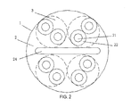
Fig. 2 , a minority of the CAT 6 cables in prior art are manufactured employing a flat-strip separator as the filler in the cable. - In
Fig. 2 , it shows acore 2, and ashield layer 1 between thecore 2 and a jacket (not shown), or ajacket 1; inside thecore 2, it is provided with four conductor sets (twisted pairs) 3 each consisting of a pair ofconductors 21,insulating layers 22 covering the conductors, and a flat-strip separator 23 among the fourtwisted pairs 3. - However, the filler solutions as described above inevitably present following unresolved technical problems:
- As for the ordinary cross-shaped separator: the cable is large in wire diameter, not flexible enough (exhibiting an inherent stiffness caused by the cross), and unable to be packaged using the cross-spool winding system (Reelex), which renders difficulty in packaging and transporting;
- As for the flat-strip separator: the cable is small in wire diameter and flexible, but unstable in structure, and also unable to be packaged using the cross-spool winding system (Reelex), which renders difficulty in packaging and transporting and unreliability in installation.
- An object of the present invention is to propose a separator structure of CAT 6 cable, which overcomes the aforementioned problems.
- To solve the abovementioned problems, the separator structure according to present invention comprises a core; a shield layer between the core and a jacket, or a jacket; four conductor sets (twisted pairs) each consisting of a pair of conductors (wires) and insulating layers covering the conductors provided inside the core; and a separator among the four conductor sets; wherein said separator has a shape of "V", the bottom end of which is located at the center of the core and the two sides of which respectively separate the adjacent conductor sets.
- The present design has such advantages over the prior art that, it is possible to use the cross-spool winding system (Reelex) in packaging as in the case of CAT 5E cable; the old reel-in-box which is necessary for CAT 6 cable package in prior art is omitted; the cable and the package thereof are compacter and lighter; cost for transportation and on-site cabling is highly reduced.
-
-
Figure 1 is a schematic diagram of the structure of the CAT 6 STP cable with a cross-shaped separator in prior art; -
Figure 2 is a schematic diagram of the structure of the CAT 6 STP cable with a flat-strip separator in prior art; and -
Figure 3 is a schematic diagram of the structure of the CAT 6 STP cable of the present invention. - The present invention will be described in detail with reference to the annexed drawings and an embodiment as follows.
- As shown in
Figure 3 , the separator structure according to present invention comprises acore 2; ashield layer 1 between thecore 2 and a jacket, or ajacket 1; four conductor sets (twisted pairs) 3 each consisting of a pair of conductors (wires) 21, andinsulating layers 22 covering the conductors provided inside thecore 2; and aseparator 25 among the fourconductor sets 3; wherein saidseparator 25 has a shape of "V", the bottom end of which is located at the center of thecore 2 and the two sides of which respectively separate theadjacent conductor sets 3 from each other; - One of the two sides of said
separator 25 separates the left-hand and right-hand conductor sets 3 from each other, and the other of the two sides of saidseparator 25 separates the upper-left and lower-left conductor sets 3 from each other. - The V-shaped separator is compact, flexible, light in weight and stable in structure, which makes the cabling easier and more reliable.
- In addition, the V-shaped separator has less combustible material, thus improving the fire-resistance and safety level.
- As compared with the conventional design with a cross or a flat strip as the separator, it is possible to use the cross-spool winding system (Reelex) in packaging as in the case of CAT 5E and omit the old reel-in-box which is necessary for packaging the CAT 6 cable in prior art. In addition to the lower cost, the new design is also more environment-friendly, because the reel is regarded to be such a kind of package garbage that is difficult to dispose, and the omission of reel eliminates the need of garbage disposal.
- The new design makes the cable and the package thereof compacter and lighter, and cost for transportation and on-site cabling is highly reduced.
Claims (2)
- A separator structure for Cat 6 cable, comprising a core (2); a shield layer (1) between the core (2) and a jacket, or a jacket (1); four conductor sets (3) each consisting of a pair of conductors (21), and insulating layers (22) covering the conductors provided inside the core (2), characterized in that, further comprising a separator (25) among the four conductor sets (3), wherein said separator (25) has a shape of "V", the bottom end of which is located at the center of the core (2) and the two sides of which respectively separate the adjacent conductor sets (3) from each other.
- A separator structure for Cat 6 cable as claimed in claim 1, characterized in that, one of the two sides of said separator (25) separates the left-hand and right-hand conductor sets (3) from each other, and the other of the two sides of said separator (25) separates the upper-left and lower-left conductor sets (3) from each other.
Applications Claiming Priority (2)
| Application Number | Priority Date | Filing Date | Title |
|---|---|---|---|
| CN2007101715552A CN101452749B (en) | 2007-11-30 | 2007-11-30 | Six kinds of cables with skeleton structure |
| PCT/CN2008/073268 WO2009074087A1 (en) | 2007-11-30 | 2008-12-01 | Frame structure of class 6 cable |
Publications (2)
| Publication Number | Publication Date |
|---|---|
| EP2219194A1 true EP2219194A1 (en) | 2010-08-18 |
| EP2219194A4 EP2219194A4 (en) | 2013-01-30 |
Family
ID=40734937
Family Applications (1)
| Application Number | Title | Priority Date | Filing Date |
|---|---|---|---|
| EP08859558A Withdrawn EP2219194A4 (en) | 2007-11-30 | 2008-12-01 | Frame structure of class 6 cable |
Country Status (7)
| Country | Link |
|---|---|
| US (1) | US9048007B2 (en) |
| EP (1) | EP2219194A4 (en) |
| KR (1) | KR101547211B1 (en) |
| CN (1) | CN101452749B (en) |
| AU (1) | AU2008336010A1 (en) |
| BR (1) | BRPI0819733A2 (en) |
| WO (1) | WO2009074087A1 (en) |
Cited By (3)
| Publication number | Priority date | Publication date | Assignee | Title |
|---|---|---|---|---|
| WO2012071290A1 (en) * | 2010-11-22 | 2012-05-31 | Commscope Inc. Of North Carolina | Twisted pair communications cable with selective separation of pairs |
| CN103971834A (en) * | 2014-04-24 | 2014-08-06 | 安徽徽宁电器仪表集团有限公司 | Thermal insulation cable |
| CN105825937A (en) * | 2016-04-22 | 2016-08-03 | 山东菲达电力电缆股份有限公司 | A skeleton, optical fiber cable and triple network fusion low-voltage photoelectric composite cable |
Families Citing this family (10)
| Publication number | Priority date | Publication date | Assignee | Title |
|---|---|---|---|---|
| CN103971831A (en) * | 2014-04-24 | 2014-08-06 | 安徽徽宁电器仪表集团有限公司 | Torsion resistant cable |
| CN103971807A (en) * | 2014-04-24 | 2014-08-06 | 安徽徽宁电器仪表集团有限公司 | Rubber flexible cable |
| CN103971826A (en) * | 2014-04-24 | 2014-08-06 | 安徽徽宁电器仪表集团有限公司 | Torsion-resistant cable |
| CN103928138A (en) * | 2014-04-26 | 2014-07-16 | 芜湖航天特种电缆厂 | Direct-current cable for offshore oil and gas drilling platform |
| CN104021852A (en) * | 2014-05-09 | 2014-09-03 | 安徽埃克森科技集团有限公司 | Wind energy cable |
| CN104021862A (en) * | 2014-05-09 | 2014-09-03 | 安徽埃克森科技集团有限公司 | Water-resistant cable |
| CN104361948A (en) * | 2014-12-02 | 2015-02-18 | 安徽渡江电缆集团有限公司 | Anti-interference communication cable |
| US10186350B2 (en) | 2016-07-26 | 2019-01-22 | General Cable Technologies Corporation | Cable having shielding tape with conductive shielding segments |
| EP3582235B1 (en) | 2018-06-14 | 2023-12-20 | General Cable Technologies Corporation | Cable having shielding tape with conductive shielding segments |
| CN110459363A (en) * | 2018-10-09 | 2019-11-15 | 安波福电气系统有限公司 | A cable structure suitable for CAT6 unshielded cables |
Family Cites Families (9)
| Publication number | Priority date | Publication date | Assignee | Title |
|---|---|---|---|---|
| US3848073A (en) * | 1973-01-15 | 1974-11-12 | Sun Chemical Corp | Shielding tapes |
| JPS5636609A (en) * | 1979-08-31 | 1981-04-09 | Nippon Telegr & Teleph Corp <Ntt> | Optical fiber cable and its production |
| FR2738947B1 (en) * | 1995-09-15 | 1997-10-17 | Filotex Sa | MULTI-PAIR CABLE, SHIELDED PER PAIR AND EASY TO CONNECT |
| FR2779866B1 (en) * | 1998-06-11 | 2000-07-13 | Alsthom Cge Alcatel | CABLE FOR TRANSMITTING INFORMATION AND ITS MANUFACTURING METHOD |
| US6300573B1 (en) * | 1999-07-12 | 2001-10-09 | The Furukawa Electric Co., Ltd. | Communication cable |
| US6624359B2 (en) * | 2001-12-14 | 2003-09-23 | Neptco Incorporated | Multifolded composite tape for use in cable manufacture and methods for making same |
| CN2904224Y (en) * | 2006-04-10 | 2007-05-23 | 杨国忠 | Data cable with frame |
| CN201126738Y (en) * | 2007-11-30 | 2008-10-01 | 耐克森凯讯(上海)电缆有限公司 | Cage construction of six series cable |
| US7834271B2 (en) * | 2008-04-30 | 2010-11-16 | Tyco Electronics Corporation | Cabling having shielding separators |
-
2007
- 2007-11-30 CN CN2007101715552A patent/CN101452749B/en not_active Expired - Fee Related
-
2008
- 2008-12-01 EP EP08859558A patent/EP2219194A4/en not_active Withdrawn
- 2008-12-01 AU AU2008336010A patent/AU2008336010A1/en not_active Abandoned
- 2008-12-01 WO PCT/CN2008/073268 patent/WO2009074087A1/en not_active Ceased
- 2008-12-01 US US12/741,449 patent/US9048007B2/en not_active Expired - Fee Related
- 2008-12-01 KR KR1020107013226A patent/KR101547211B1/en not_active Expired - Fee Related
- 2008-12-01 BR BRPI0819733A patent/BRPI0819733A2/en not_active IP Right Cessation
Cited By (4)
| Publication number | Priority date | Publication date | Assignee | Title |
|---|---|---|---|---|
| WO2012071290A1 (en) * | 2010-11-22 | 2012-05-31 | Commscope Inc. Of North Carolina | Twisted pair communications cable with selective separation of pairs |
| US8759680B2 (en) | 2010-11-22 | 2014-06-24 | Commscope, Inc. Of North Carolina | Twisted pair communications cable with selective separation of pairs |
| CN103971834A (en) * | 2014-04-24 | 2014-08-06 | 安徽徽宁电器仪表集团有限公司 | Thermal insulation cable |
| CN105825937A (en) * | 2016-04-22 | 2016-08-03 | 山东菲达电力电缆股份有限公司 | A skeleton, optical fiber cable and triple network fusion low-voltage photoelectric composite cable |
Also Published As
| Publication number | Publication date |
|---|---|
| WO2009074087A1 (en) | 2009-06-18 |
| CN101452749B (en) | 2013-03-20 |
| KR20100088156A (en) | 2010-08-06 |
| KR101547211B1 (en) | 2015-08-26 |
| AU2008336010A1 (en) | 2009-06-18 |
| EP2219194A4 (en) | 2013-01-30 |
| BRPI0819733A2 (en) | 2019-09-24 |
| US20110017492A1 (en) | 2011-01-27 |
| US9048007B2 (en) | 2015-06-02 |
| CN101452749A (en) | 2009-06-10 |
Similar Documents
| Publication | Publication Date | Title |
|---|---|---|
| US9048007B2 (en) | Separator structure for Cat 6 cable | |
| CN102209994B (en) | Communication cable with improved crosstalk attenuation | |
| US11025345B2 (en) | Hybrid cable providing data transmission through fiber optic cable and low voltage power over copper wire | |
| JP3589348B2 (en) | Electric / optical composite cable | |
| CN202067602U (en) | Repeater type photoelectric composite cable for metal armouring wire | |
| CN201126738Y (en) | Cage construction of six series cable | |
| CN1327455C (en) | Photoelectric comprehensive cable | |
| CN102122546A (en) | Mixed optical cable with cross support | |
| CN201853534U (en) | Hybrid optical cable with cross bracing | |
| CN201191535Y (en) | Low cross talk photoelectric mixed cable having shielding compartment | |
| CN203260402U (en) | Copper conductor straightly-placed ratproof photoelectric mixing cable | |
| CN202149952U (en) | Household multifunctional information case | |
| CN103824643A (en) | Triangle communication cable | |
| CN201994134U (en) | Bundling-type multi-core composite cable | |
| CN201994136U (en) | Armored cable-core straightly-placed wire type optical-power composite cable | |
| CN201936680U (en) | Novel intelligent composite optical cable | |
| CN216697948U (en) | 8-shaped data communication composite cable | |
| CN217606607U (en) | Low-cost aluminum alloy core photoelectric composite cable | |
| CN207517397U (en) | A kind of novel photoelectric composite cable | |
| CN214847893U (en) | Novel unshielded twisted pair | |
| CN211294724U (en) | Mixed cable | |
| CN201194183Y (en) | High Performance Data Cable | |
| CN211788327U (en) | Composite cable for equipment connection | |
| CN201177996Y (en) | A figure-of-eight digital communication cable | |
| CN202948782U (en) | Data and image transmission composite cable |
Legal Events
| Date | Code | Title | Description |
|---|---|---|---|
| PUAI | Public reference made under article 153(3) epc to a published international application that has entered the european phase |
Free format text: ORIGINAL CODE: 0009012 |
|
| 17P | Request for examination filed |
Effective date: 20100630 |
|
| AK | Designated contracting states |
Kind code of ref document: A1 Designated state(s): AT BE BG CH CY CZ DE DK EE ES FI FR GB GR HR HU IE IS IT LI LT LU LV MC MT NL NO PL PT RO SE SI SK TR |
|
| AX | Request for extension of the european patent |
Extension state: AL BA MK RS |
|
| DAX | Request for extension of the european patent (deleted) | ||
| A4 | Supplementary search report drawn up and despatched |
Effective date: 20130107 |
|
| RIC1 | Information provided on ipc code assigned before grant |
Ipc: H01B 11/06 20060101ALI20121221BHEP Ipc: H01B 11/00 20060101AFI20121221BHEP Ipc: H01B 7/17 20060101ALI20121221BHEP Ipc: H01B 7/18 20060101ALI20121221BHEP |
|
| RIC1 | Information provided on ipc code assigned before grant |
Ipc: H01B 11/06 20060101ALI20130305BHEP Ipc: H01B 11/00 20060101AFI20130305BHEP Ipc: H01B 7/18 20060101ALI20130305BHEP Ipc: H01B 7/17 20060101ALI20130305BHEP |
|
| 17Q | First examination report despatched |
Effective date: 20140717 |
|
| 17Q | First examination report despatched |
Effective date: 20140829 |
|
| GRAP | Despatch of communication of intention to grant a patent |
Free format text: ORIGINAL CODE: EPIDOSNIGR1 |
|
| INTG | Intention to grant announced |
Effective date: 20151022 |
|
| STAA | Information on the status of an ep patent application or granted ep patent |
Free format text: STATUS: THE APPLICATION IS DEEMED TO BE WITHDRAWN |
|
| 18D | Application deemed to be withdrawn |
Effective date: 20160302 |