EP2219092A1 - Méthode de contrôle de la vitesse d'un véhicule - Google Patents
Méthode de contrôle de la vitesse d'un véhicule Download PDFInfo
- Publication number
- EP2219092A1 EP2219092A1 EP10152454A EP10152454A EP2219092A1 EP 2219092 A1 EP2219092 A1 EP 2219092A1 EP 10152454 A EP10152454 A EP 10152454A EP 10152454 A EP10152454 A EP 10152454A EP 2219092 A1 EP2219092 A1 EP 2219092A1
- Authority
- EP
- European Patent Office
- Prior art keywords
- speed
- stretch
- vehicle
- max
- current
- Prior art date
- Legal status (The legal status is an assumption and is not a legal conclusion. Google has not performed a legal analysis and makes no representation as to the accuracy of the status listed.)
- Granted
Links
- 238000000034 method Methods 0.000 title claims abstract description 33
- 230000003068 static effect Effects 0.000 claims abstract description 38
- 230000006870 function Effects 0.000 claims description 64
- 239000000446 fuel Substances 0.000 claims description 31
- 230000009467 reduction Effects 0.000 claims description 27
- 238000013461 design Methods 0.000 claims description 12
- 230000001133 acceleration Effects 0.000 claims description 11
- 230000003247 decreasing effect Effects 0.000 claims description 3
- 230000000007 visual effect Effects 0.000 claims description 3
- 230000009471 action Effects 0.000 claims description 2
- 230000000750 progressive effect Effects 0.000 claims description 2
- 230000002829 reductive effect Effects 0.000 claims description 2
- 230000007704 transition Effects 0.000 claims 1
- 230000007935 neutral effect Effects 0.000 description 7
- 230000005540 biological transmission Effects 0.000 description 6
- 230000001276 controlling effect Effects 0.000 description 4
- 238000012360 testing method Methods 0.000 description 4
- 230000008859 change Effects 0.000 description 3
- 230000001172 regenerating effect Effects 0.000 description 3
- 230000001105 regulatory effect Effects 0.000 description 3
- 230000006399 behavior Effects 0.000 description 2
- 239000003344 environmental pollutant Substances 0.000 description 2
- 238000007620 mathematical function Methods 0.000 description 2
- 231100000719 pollutant Toxicity 0.000 description 2
- 238000009877 rendering Methods 0.000 description 2
- 238000004088 simulation Methods 0.000 description 2
- 230000005526 G1 to G0 transition Effects 0.000 description 1
- 238000013459 approach Methods 0.000 description 1
- 238000002485 combustion reaction Methods 0.000 description 1
- 230000007423 decrease Effects 0.000 description 1
- 230000000694 effects Effects 0.000 description 1
- 238000011156 evaluation Methods 0.000 description 1
- 230000014509 gene expression Effects 0.000 description 1
- 238000002347 injection Methods 0.000 description 1
- 239000007924 injection Substances 0.000 description 1
- 238000009434 installation Methods 0.000 description 1
- 230000000670 limiting effect Effects 0.000 description 1
- 238000005259 measurement Methods 0.000 description 1
- 238000005086 pumping Methods 0.000 description 1
- 230000004044 response Effects 0.000 description 1
- 230000002441 reversible effect Effects 0.000 description 1
- 239000000243 solution Substances 0.000 description 1
Images


Classifications
-
- B—PERFORMING OPERATIONS; TRANSPORTING
- B60—VEHICLES IN GENERAL
- B60W—CONJOINT CONTROL OF VEHICLE SUB-UNITS OF DIFFERENT TYPE OR DIFFERENT FUNCTION; CONTROL SYSTEMS SPECIALLY ADAPTED FOR HYBRID VEHICLES; ROAD VEHICLE DRIVE CONTROL SYSTEMS FOR PURPOSES NOT RELATED TO THE CONTROL OF A PARTICULAR SUB-UNIT
- B60W30/00—Purposes of road vehicle drive control systems not related to the control of a particular sub-unit, e.g. of systems using conjoint control of vehicle sub-units, or advanced driver assistance systems for ensuring comfort, stability and safety or drive control systems for propelling or retarding the vehicle
- B60W30/14—Adaptive cruise control
- B60W30/143—Speed control
- B60W30/146—Speed limiting
-
- B—PERFORMING OPERATIONS; TRANSPORTING
- B60—VEHICLES IN GENERAL
- B60W—CONJOINT CONTROL OF VEHICLE SUB-UNITS OF DIFFERENT TYPE OR DIFFERENT FUNCTION; CONTROL SYSTEMS SPECIALLY ADAPTED FOR HYBRID VEHICLES; ROAD VEHICLE DRIVE CONTROL SYSTEMS FOR PURPOSES NOT RELATED TO THE CONTROL OF A PARTICULAR SUB-UNIT
- B60W30/00—Purposes of road vehicle drive control systems not related to the control of a particular sub-unit, e.g. of systems using conjoint control of vehicle sub-units, or advanced driver assistance systems for ensuring comfort, stability and safety or drive control systems for propelling or retarding the vehicle
- B60W30/18—Propelling the vehicle
- B60W30/188—Controlling power parameters of the driveline, e.g. determining the required power
-
- B—PERFORMING OPERATIONS; TRANSPORTING
- B60—VEHICLES IN GENERAL
- B60W—CONJOINT CONTROL OF VEHICLE SUB-UNITS OF DIFFERENT TYPE OR DIFFERENT FUNCTION; CONTROL SYSTEMS SPECIALLY ADAPTED FOR HYBRID VEHICLES; ROAD VEHICLE DRIVE CONTROL SYSTEMS FOR PURPOSES NOT RELATED TO THE CONTROL OF A PARTICULAR SUB-UNIT
- B60W40/00—Estimation or calculation of non-directly measurable driving parameters for road vehicle drive control systems not related to the control of a particular sub unit, e.g. by using mathematical models
- B60W40/02—Estimation or calculation of non-directly measurable driving parameters for road vehicle drive control systems not related to the control of a particular sub unit, e.g. by using mathematical models related to ambient conditions
- B60W40/06—Road conditions
- B60W40/072—Curvature of the road
-
- B—PERFORMING OPERATIONS; TRANSPORTING
- B60—VEHICLES IN GENERAL
- B60W—CONJOINT CONTROL OF VEHICLE SUB-UNITS OF DIFFERENT TYPE OR DIFFERENT FUNCTION; CONTROL SYSTEMS SPECIALLY ADAPTED FOR HYBRID VEHICLES; ROAD VEHICLE DRIVE CONTROL SYSTEMS FOR PURPOSES NOT RELATED TO THE CONTROL OF A PARTICULAR SUB-UNIT
- B60W40/00—Estimation or calculation of non-directly measurable driving parameters for road vehicle drive control systems not related to the control of a particular sub unit, e.g. by using mathematical models
- B60W40/02—Estimation or calculation of non-directly measurable driving parameters for road vehicle drive control systems not related to the control of a particular sub unit, e.g. by using mathematical models related to ambient conditions
- B60W40/06—Road conditions
- B60W40/076—Slope angle of the road
-
- B—PERFORMING OPERATIONS; TRANSPORTING
- B60—VEHICLES IN GENERAL
- B60W—CONJOINT CONTROL OF VEHICLE SUB-UNITS OF DIFFERENT TYPE OR DIFFERENT FUNCTION; CONTROL SYSTEMS SPECIALLY ADAPTED FOR HYBRID VEHICLES; ROAD VEHICLE DRIVE CONTROL SYSTEMS FOR PURPOSES NOT RELATED TO THE CONTROL OF A PARTICULAR SUB-UNIT
- B60W50/00—Details of control systems for road vehicle drive control not related to the control of a particular sub-unit, e.g. process diagnostic or vehicle driver interfaces
- B60W50/0097—Predicting future conditions
-
- B—PERFORMING OPERATIONS; TRANSPORTING
- B60—VEHICLES IN GENERAL
- B60W—CONJOINT CONTROL OF VEHICLE SUB-UNITS OF DIFFERENT TYPE OR DIFFERENT FUNCTION; CONTROL SYSTEMS SPECIALLY ADAPTED FOR HYBRID VEHICLES; ROAD VEHICLE DRIVE CONTROL SYSTEMS FOR PURPOSES NOT RELATED TO THE CONTROL OF A PARTICULAR SUB-UNIT
- B60W2556/00—Input parameters relating to data
- B60W2556/45—External transmission of data to or from the vehicle
- B60W2556/50—External transmission of data to or from the vehicle for navigation systems
-
- B—PERFORMING OPERATIONS; TRANSPORTING
- B60—VEHICLES IN GENERAL
- B60W—CONJOINT CONTROL OF VEHICLE SUB-UNITS OF DIFFERENT TYPE OR DIFFERENT FUNCTION; CONTROL SYSTEMS SPECIALLY ADAPTED FOR HYBRID VEHICLES; ROAD VEHICLE DRIVE CONTROL SYSTEMS FOR PURPOSES NOT RELATED TO THE CONTROL OF A PARTICULAR SUB-UNIT
- B60W2720/00—Output or target parameters relating to overall vehicle dynamics
- B60W2720/10—Longitudinal speed
- B60W2720/103—Speed profile
-
- Y—GENERAL TAGGING OF NEW TECHNOLOGICAL DEVELOPMENTS; GENERAL TAGGING OF CROSS-SECTIONAL TECHNOLOGIES SPANNING OVER SEVERAL SECTIONS OF THE IPC; TECHNICAL SUBJECTS COVERED BY FORMER USPC CROSS-REFERENCE ART COLLECTIONS [XRACs] AND DIGESTS
- Y02—TECHNOLOGIES OR APPLICATIONS FOR MITIGATION OR ADAPTATION AGAINST CLIMATE CHANGE
- Y02T—CLIMATE CHANGE MITIGATION TECHNOLOGIES RELATED TO TRANSPORTATION
- Y02T10/00—Road transport of goods or passengers
- Y02T10/10—Internal combustion engine [ICE] based vehicles
- Y02T10/40—Engine management systems
-
- Y—GENERAL TAGGING OF NEW TECHNOLOGICAL DEVELOPMENTS; GENERAL TAGGING OF CROSS-SECTIONAL TECHNOLOGIES SPANNING OVER SEVERAL SECTIONS OF THE IPC; TECHNICAL SUBJECTS COVERED BY FORMER USPC CROSS-REFERENCE ART COLLECTIONS [XRACs] AND DIGESTS
- Y02—TECHNOLOGIES OR APPLICATIONS FOR MITIGATION OR ADAPTATION AGAINST CLIMATE CHANGE
- Y02T—CLIMATE CHANGE MITIGATION TECHNOLOGIES RELATED TO TRANSPORTATION
- Y02T10/00—Road transport of goods or passengers
- Y02T10/80—Technologies aiming to reduce greenhouse gasses emissions common to all road transportation technologies
- Y02T10/84—Data processing systems or methods, management, administration
Definitions
- the present invention relates to a method for controlling the speed of a vehicle.
- Each driver drives his own vehicle, principally following two objectives that are in contrast with one another: reducing to the minimum the travel time and reducing to the minimum fuel consumption (and hence, indirectly, the pollutants produced). Since these two objectives are mutually antithetic, the problem arises of approaching achievement of both by finding an optimal point of equilibrium.
- the document No. US2004068359A1 describes a method for controlling the speed of a vehicle that envisages: determining a current stretch of a path of the vehicle; determining a recommended maximum speed for the current stretch of the path of the vehicle; and determining an optimal speed for the current stretch of the path of the vehicle as a function of the corresponding recommended maximum speed.
- the aim of the present invention is to provide a method for controlling the speed of a vehicle, said the control method enabling an optimal balance to be obtained between the reduction of the travel time and the reduction of fuel consumption and, in particular, being easy to use even for a non-expert driver and being easy and economically advantageous to implement on an existing vehicle.
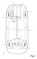
- FIG. 1 designated as a whole by the number 1 is an automobile provided with two front wheels 2 and two rear driving wheels 3, which receive the torque generated by an internal-combustion engine 4 set in a front position by means of a servo transmission 5.
- the servo transmission 5 comprises a servo clutch 6, which is housed in a bell fixed with respect to the engine 4 and is designed to connect a crankshaft 7 of the engine 4 to a transmission shaft 8 terminating in a mechanical servo gearchange 9.
- Cascaded to the servo gearchange 9 is a differential 10, departing from which is a pair of axleshafts 11, each of which is fixed with respect to a respective rear driving wheel 2.
- the automobile 1 comprises a control unit 12, which is able to control the speed of the automobile 1 both by acting on the generation of the torque by driving the engine 4 and by acting on the transmission of the torque by acting on the servo transmission 5.
- the control unit 12 is connected to a satellite navigator 13 (which can be integrated within the control unit 12 or can be separate from the control unit 12), which is designed to determine (or in any case at least foresee) both the path that must be covered by the automobile 1 and the current position and speed of the automobile 1 along the path itself.
- the satellite navigator 13 For each stretch of path, the satellite navigator 13 is able to supply the recommended maximum speed V MAX for the stretch of path itself, normally on the straight the recommended maximum speed V MAX for each stretch of path coinciding with the speed limit imposed by the highway code and coinciding with a lower value in the presence of bends, humps, crossroads, and other points that present difficulties and must be approached with caution.
- the control unit 12 is connected to an acquisition device 14, which is able to "read” the road signals (including traffic lights) in front of the automobile 1 by means of a video camera and/or by means of a radio connection with radiotransmitters carried by the road signals themselves.
- the radiotransmitter is able to supply both the state of the traffic light (green, yellow or red) and the time that remains before the traffic lights change.
- the acquisition device 14 could be able to receive via radio information supplied by information control units located, for example, in the proximity of road accidents or in areas with high traffic density (to supply, for example, the average speed of the queue) and information on the weather conditions (temperature, presence of rain, ice), etc.
- information control units located, for example, in the proximity of road accidents or in areas with high traffic density (to supply, for example, the average speed of the queue) and information on the weather conditions (temperature, presence of rain, ice), etc.
- control unit 12 can be connected to a system of video cameras and/or radars for identifying, in the path of the vehicle 1, the presence of other vehicles or of other objects and information on their speed. Said information is useful for modifying the speed of the vehicle 1 not only for reasons of safety, but also for slowing down and avoiding any need for jamming on the brakes (this behaviour is advantageous from the standpoint of fuel saving).
- an interface device 15 which enables the driver to interact with the control unit 12; in particular, by means of the interface device 15 the driver can read the current value and modify the current value by a coefficient k S of static saving, which is variable within a given range (typically between 0.2 and 2) and indicates to what extent the saving on the travel time must prevail over the energy saving during the phases at constant speed (i.e., in static conditions).
- the interface device 15 can present to the driver the value of the coefficient k S of static saving in a different way from the effective numeric value; for example, the interface device 15 can present to the driver the value of the coefficient k S of static saving in percentage terms (for example 0% corresponds to the value 0.2, and 100% corresponds to the value 2, or vice versa).
- the driver can read the current value and modify the current value by a coefficient k D of dynamic saving, which is variable within a given range and indicates to what extent the saving on the travel time must prevail over the energy saving during the phases at variable speed (i.e., in acceleration or in deceleration, that is, in dynamic conditions).
- a single coefficient K of saving is envisaged, which is used both during phases at constant speed, and during phases at variable speed; in other words, the single coefficient K of saving replaces the coefficient k S of static saving, and the coefficient k D of dynamic saving being interpreted differently for stationary phases (characterized by constant speed) and for transitory or dynamic phases (characterized by accelerations or decelerations).
- the control unit 12 determines each time the optimal speed V O of the automobile 1 that is comprised between zero (lower limit that is reached when it is necessary to stop the automobile 1, for example in front of a red traffic light) and the recommended maximum speed V MAX .
- the mission of the control unit 12 is to determine for each stretch of the path of the automobile 1 what is the optimal speed V O (which is always lower than or, at the most, equal to the recommended maximum speed V MAX ). All other conditions being equal, a reduction of the speed of the automobile 1 generally enables a reduction of fuel consumption but at the same time entails an increase in the travel time.
- the control unit 12 determine for each stretch of the path of the automobile 1 what is the optimal speed V O , which represents the point of optimal equilibrium between the objective of reducing fuel consumption and the objective of reducing the travel time.
- the fuel consumption of the automobile 1 is determined as the speed varies, and hence an experimental law is determined, which yields the fuel consumption of the automobile 1 as a function of the speed; by way of example, illustrated in the graph of Figure 2 is a real example of an experimental law that yields the fuel consumption of the automobile 1 as a function of the speed.
- the gear ratio 9 is chosen to optimize operation of the engine 4, i.e., generally to reduce as far as possible the r.p.m. of the engine 4 without jeopardizing proper operation of the engine 4 itself (i.e., to get the engine 4 to work in conditions of maximum efficiency).
- Illustrated in Figure 2 is the experimental law that yields the fuel consumption of the automobile 1 as a function of the speed in the case of zero slope; in general, said experimental law is parameterized as a function of the slope, which can be either positive (uphill, hence consumption penalized) or negative (downhill, hence consumption favoured).
- a cost function F C is defined, which, given a certain recommended maximum speed V MAX and a speed V lower than the recommended maximum speed V MAX , yields the overall "cost" of the reduction of the speed from the recommended maximum speed V MAX to the speed V and is calculated by adding algebraically to the percentage variation in consumption ⁇ C% (which is in general negative) obtained as a result of the reduction of the speed the percentage variation of the travel time ⁇ T% (which is always positive) obtained as a result of the reduction of the speed.
- Entered into the cost function F C is also the coefficient k S of static saving, which varies the weight of the percentage variation in consumption ⁇ C% with respect to the percentage variation of the travel time ⁇ T%.
- the coefficient k S of static saving is used as multiplicative coefficient of the percentage variation of the travel time.
- the coefficient k S of static saving when the coefficient k S of static saving is lower than 1 it determines a greater weight of the fuel consumption with respect to the travel time; when the coefficient k S of static saving is equal to 1 it does not have any effect; and when the coefficient k S of static saving is higher than 1 it determines a smaller weight of the fuel consumption with respect to the travel time.
- the coefficient k S of static saving could be used as multiplicative coefficient of the percentage variation in consumption ⁇ C%, as quotient of the percentage variation of the travel time ⁇ T%, or else as quotient of the percentage variation in consumption ⁇ C%.
- the functions T(V) and C(V) described above that yield the travel time and the fuel consumption of the automobile 1 at the speed V determine the travel time and the fuel consumption of the automobile 1 for covering a reference stretch of standard and predefined length (for example, 1 km or else 10 km or else 100 km). Given the length of the reference stretch and the speed of the automobile 1 the travel time is determined by means of a simple division; moreover, given the length of the reference stretch and the speed of the automobile 1, the unit consumption at this speed is determined by means of an experimental law of the type like the one illustrated in Figure 2 , and hence fuel consumption is determined by means of a simple division. It should then be emphasized that the units of measurement with which the functions T(V) and C(V) are expressed have no importance given that the cost function F C is normalized and expressed in percentage terms.
- the corresponding optimal speed V O is the speed that yields the minimum absolute value of the cost function F C .
- the determination of the optimal speeds V O is made by means of known mathematical techniques of determination of the minimum of a function (typically using numerical methodologies with the aid of a computer, in so far as the experimental law that yields the unit consumption as a function of the speed is not simply expressible with a mathematical function); obviously, there is always present the constraint that the optimal speed V O cannot be higher than the recommended maximum speed V MAX .
- a law is determined, which, as a function of the recommended maximum speed V MAX yields the optimal speed V O and is parameterized as a function of the coefficient k S of static saving; a real example of said law is graphically illustrated in Figure 3 , where it appears immediately evident that given the same recommended maximum speed V MAX the optimal speed V O increases as the coefficient k S of static saving increases.
- the control unit 12 determines by means of the satellite navigator 13 the path of the automobile 1 and then determines the current stretch of path (i.e., the stretch of path in which the automobile 1 is located and is hence currently occupied by the automobile 1) and the recommended maximum speed V MAX for the current stretch; as a function of the recommended maximum speed V MAX for the current stretch and as a function of the coefficient k S of static saving selected by the driver, the control unit 12, using the law determined in the design stage, determines the corresponding optimal speed V O and then drives the engine 4 (and if necessary the gearchange 9) in a known way to get the automobile 1 to travel at the optimal speed V O .
- the control unit 12 updates the corresponding optimal speed V O , as has been described above.
- the amplitude of the stretches of the path is not uniform, but depends upon the context: on a motorway, the length of the stretches is much greater than on a local road that traverses built-up areas.
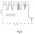
- Figure 4 is a graphic illustration of a real example of a profile of the recommended maximum speed V MAX (solid line) and of the optimal speed V O (dashed line) of the automobile 1 along a testing path of approximately 4 km using a coefficient k S of static saving equal to 0.85 (hence a coefficient k S of static saving that favours slightly the reduction of fuel consumption over the reduction of the travel time).
- the navigator 13 knowing or estimating with an internal algorithm of its own the future path of the vehicle 1, is able to inform the control unit 12 of a certain number of future variations of the recommended maximum speed V MAX and hence of the optimal speeds V O ; the control unit 12 then has the task of deciding what is, if it exists, the point on which to calculate the profile of deceleration as a function of the current speed of the vehicle 1, of the future speed constraints, and of the respective distances of application.
- the rule of adjustment of the speed envisages that, when the optimal speed V O for the current stretch is lower than the optimal speed V O for the subsequent stretch, the adjustment of the speed (i.e., the acceleration of the automobile 1) occurs entirely in the subsequent stretch; in other words, when the optimal speed V O for the current stretch is lower than the optimal speed V O for the subsequent stretch, the current stretch is entirely covered at its own optimal speed V O and in the initial part of the subsequent stretch a progressive acceleration is made to reach progressively the optimal speed V O for the subsequent stretch.
- the acceleration is never violent in so far as during a violent acceleration the engine 4 works in conditions far from maximum efficiency.
- the mean value of the acceleration during adjustment of the speed is variable as a function of the coefficient k D of dynamic saving so that the more the coefficient k D of dynamic saving favours the reduction of fuel consumption, the more the mean value of the acceleration is reduced.
- the rule of adjustment of the speed envisages that, when the optimal speed V O for the current stretch is higher than the optimal speed V O for the subsequent stretch, the adjustment of the speed (i.e., the deceleration of the automobile 1) occurs entirely in the current stretch; in other words, when the optimal speed V O for the current stretch is higher than the optimal speed V O for the subsequent stretch, the last part of the current stretch is covered at a progressively decreasing speed to reach progressively the optimal speed V O for the subsequent stretch.
- the deceleration is never violent, and, in the limits of possibility, it is not necessary to apply the brakes but only use an inertial motion of the automobile 1 so as not to dissipate the kinetic energy possessed by the automobile 1.
- the automobile 1 in deceleration the automobile 1 is allowed to advance by inertia with the engine 4 cut off (i.e., driven by the rear driving wheels 3 without fuel injection and hence without fuel consumption) starting from a distance from the start of the subsequent stretch such as to allow the automobile 1 to reach the start of the subsequent stretch at the desired speed.
- the deceleration of the automobile 1 is always a function of the desire of the driver, which is expressed through the coefficient k D of dynamic saving; when the coefficient k D of dynamic saving expresses a high attention to the reduction of fuel consumption, the deceleration may be made even with the engine turned off and the gear in neutral so as not to disperse energy in pumping of the cylinders and in friction of the engine 4 and of the transmission 5.
- the control unit 12 must evaluate whether it is possible to turn off the engine 4 in conditions of safety, i.e., whether the path envisages (even potentially) many applications of the brake, as for example happens in the presence of negative slopes, a series of bends, or intense traffic.
- a solution to this problem is the use of a servo brake actuated by an electric motor that is supplied by the battery of the automobile 1 and hence does not depend directly upon the engine 4 for its operation.
- the navigator 13 is in any case able to supply to the control unit 12 information regarding the presence of slopes, bends, crossroads, etc., hence putting the control unit 12 into conditions of sending commands for turning off the engine 4 and engaging the neutral only when said operation presents a high degree of safety.
- a law of inertial motion is determined that, in conditions of cut-off or in conditions of engine 4 turned off and neutral gear and starting from a given starting speed, yields the evolution of the speed of the automobile 1 as a function of the distance covered, all this being determined also as a function of the slope (whether positive or negative), considering that this information can be estimated by the control unit 12 or transmitted by the navigator 13.
- This law of inertial motion can be expressed by means of a mathematical function containing parameters determined experimentally or else can be expressed by means of an experimental table.
- the control unit 12 determines, also according to the slope, the space required for the automobile 1 to slow down to reach the final speed (optimal speed V O for the subsequent stretch) starting from the initial speed (optimal speed V O for the current stretch); hence, when the automobile 1 is at a distance equal to the space for slowing down from the start of the subsequent stretch, the control unit 12 turns off the engine 4 (i.e., it sets the engine 4 in conditions of cut-off and possibly disconnected from the rear driving wheels 3 as a function of the coefficient k D of dynamic saving) to proceed with an inertial motion up to the start of the subsequent stretch.
- the control unit 12 turns off the engine 4 (i.e., it sets the engine 4 in conditions of cut-off and possibly disconnected from the rear driving wheels 3 as a function of the coefficient k D of dynamic saving) to proceed with an inertial motion up to the start of the subsequent stretch.
- control unit 12 can also envisage using the brakes in the proximity of the start of the subsequent stretch; the intervention of the brakes will be all the more important, the more the coefficient k D of dynamic saving favours the reduction of the travel time.
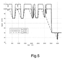
- Figure 5 is a graphic illustration a real example of a profile of the recommended maximum speed V MAX (solid line), optimal speed V O-S in static conditions (dashed line), i.e., without application of the rule of adjustment of the speed described above, and optimal speed V O-D in dynamic conditions (dashed-and-dotted line), i.e., with application of the rule of adjustment of the speed of the automobile 1 described above, along a testing path of approximately 4 km using a coefficient k S of static saving equal to 0.85 (hence a coefficient k S of static saving that slightly favours the reduction of fuel consumption over the reduction of the travel time) and using a coefficient k D of dynamic saving that leads to the engine 4 being turned off during deceleration without, however, disconnecting the engine 4 from the rear driving wheels 3.
- control unit 12 is not able to determine the optimal speed V O in dynamic conditions, but is able to determine only the optimal speed V O in static conditions.
- control unit 12 could receive in real time the information supplied by the acquisition device 14 regarding the limits imposed by the variable road signals (typically traffic lights) in front of the automobile 1; in response to particular constraints imposed by the variable road signals, the control unit 12 temporarily modifies the optimal speed V O to take into account said constraints in an efficient and effective way. For example, if a red traffic light is detected, the control unit 12 sets the engine 4 in cut-off (or turns off the engine 4 with gear in neutral) to be able to reach the traffic light gradually, minimizing fuel consumption.
- V O the optimal speed V O to take into account said constraints in an efficient and effective way. For example, if a red traffic light is detected, the control unit 12 sets the engine 4 in cut-off (or turns off the engine 4 with gear in neutral) to be able to reach the traffic light gradually, minimizing fuel consumption.
- the dialogue via radio between the acquisition device 14 and the control unit of the "speaking” traffic lights enables acquisition both of the current state of the traffic lights and of the time that remains before the subsequent change of state; in this case, knowing the distance from the traffic lights, the state of the traffic lights, and the time that remains before the subsequent change of state, the control unit 12 can determine the most efficient law of motion to pass through the crossroads regulated by the traffic lights.
- the control unit 12 evaluates whether it is possible to pass through the crossroads regulated by the traffic lights in conditions of safety (possibly also by accelerating the automobile 1 up to the recommended maximum speed V MAX for the current stretch) or else whether it is necessary to slow down and then to stop the automobile 1 in front of the red traffic light. In the latter case, generally the control unit 12 sets the engine 4 in cut-off (or turns off the engine 4 with gear in neutral) to be able to reach the traffic light gradually, thus minimizing the fuel consumption. Instead, if the traffic light is on red, the control unit 12, knowing the time to wait for the green and the distance from the traffic lights, determines the law of motion for the traffics light just after it has changed state from red to green.
- control unit 12 could receive in real time from a system of video cameras and/or radars the information regarding the presence on the path of the vehicle 1 of other vehicles and information regarding their speed. All this can be useful not only for requirements of safety, but also for reducing fuel consumption since it is possible in time to reduce the speed and hence the torque generated by the engine to avoid any subsequent jamming-on of the brakes.
- control unit 12 receives in real time information on the presence along the path of the vehicle 1 of other vehicles or other objects and of their speed, determines any potential interference (bumping) with other vehicles or other objects along the path of the vehicle if it advances at the current optimal speed V O , and decreases temporarily and progressively the optimal speed V O to slow down the vehicle 1 temporarily so as to prevent any interference with other vehicles or other objects along the path of the vehicle 1.
- the constant speed can be energetically less advantageous (i.e., it may present higher consumption levels) than the speed that alternates cyclically phases of active motion and passive motion in so far as in phases of active motion the engine 4 can be made to work in conditions of maximum efficiency.
- the simulations on the behaviour of the vehicle 1 for determining the type of optimal motion are not made each time by the control unit 12, but are made during the design stage, and the results of the simulations are stored in a memory of the control unit 12.
- a table is present, which, as a function of the desired average speed, yields whether it is more advantageous from the energy standpoint to proceed at a constant speed or else whether it is more advantageous from the energy standpoint to proceed by alternating cyclically a phase of active motion and a phase of passive motion; moreover, when it is more advantageous from the energy standpoint to proceed by alternating cyclically a phase of active motion and a phase of passive motion, the table also yields the ideal ratio between the duration of the phase of active motion and the duration of the phase of passive motion.
- the control unit 12 verifies whether it is more advantageous from the energy standpoint to proceed at a constant speed equal to the current optimal speed V O or else whether it is more advantageous from the energy standpoint to proceed by alternating cyclically a phase of active motion and a phase of passive motion so as to obtain an average speed equal to the current optimal speed V O , and obviously uses the modes that are most advantageous from the energy standpoint.
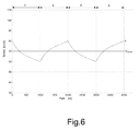
- the vehicle 1 has an accelerated motion, during which the instantaneous speed (designated by the letter V in Figure 6 ) is progressively increasing until it reaches a maximum value that is higher than the current optimal speed V O and is equal to the average speed V MEAN , whereas, during the phase of passive motion, the vehicle 1 presents a decelerated motion in which the instantaneous speed is progressively decreasing until it reaches a minimum value lower than the current optimal speed V O .
- the instantaneous speed oscillates cyclically about the current optimal speed V O , which is equal to the average speed V MEAN .
- the mode of operation described above in which the vehicle cyclically alternates a phase of active motion (in which the engine 4 is turned on and is connected to the rear driving wheels 3 through the gearchange 9) and a phase of passive motion or motion by inertia (in which the engine 4 is turned off and is disconnected from the rear driving wheels 3), can be used also independently of the determination of the recommended maximum speed V MAX and of the subsequent determination of the optimal speed V O .
- the driver who is about to embark upon a sufficiently long stretch that can potentially be travelled along at a constant speed (typically, but not only, a stretch of motorway), communicates to the control unit 12 the desired average speed that it is intended to maintain by means of the interface device 15 and leaves to the control unit 12 the task of "implementing" said desired average speed in the most economic advantageous way possible. Maintaining the requirement of obtaining the desired average speed, the control unit 12 decides whether it is more advantageous from the energy standpoint to proceed at a constant speed equal to the desired average speed or else whether it is more advantageous from the energy standpoint to proceed by alternating cyclically a phase of active motion and a phase of passive motion. In addition, once it has been established that it is more advantageous to proceed by alternating cyclically a phase of active motion and a phase of passive motion, the control unit 12 establishes the ideal ratio between the duration of the phase of active motion and the duration of the phase passive motion.
- a constant speed typically, but not only, a stretch of motorway
- the optimal speed V O determined by the control unit 12 can be directly implemented by the control unit 12 itself, or else may only be recommended to the driver by means of a purposely provided visual and/or acoustic warning issued by the interface device 15.
- the interface device 15 could also display an estimate of the variation of the fuel consumption (and possibly also an estimate of the variation of the travel time) if one were to proceed at the optimal speed V O instead of at the current speed.
- the optimal speed V O determined by the control unit 12 can be directly implemented by the control unit 12 itself, or else may only be recommended to the driver, to whom the complete control of the accelerator is left; also in the former case the driver must anyway be able immediately to take over full control of the vehicle 1 freeing himself from the control of tracking of the speed performed by the control unit 12, for example by acting also slightly on the brake pedal. Once the driver wants the control unit 12 to resume control, this must be possible with the same ease, without the driver himself having to make an explicit request.
- Two different cases may thus arise: in the first, the driver accelerates with respect to the optimal speed V O , for example to overtake, in which case it is sufficient to release the accelerator pedal to enable the control unit 12 to resume control gradually; in the second case, instead, the driver brakes, and then the control unit 12 will resume tracking of the optimal speed V O if and only if it is the driver himself who brings the vehicle 1 for a calibratable time into the neighbourhood of the same optimal speed V O .
- the driver may perform downloading of the data on the journey that has just terminated (typically via USB port or the like) and, by means of a purposely provided program implemented in a personal computer, may verify his own style of driving (for example, by superimposing the path covered on a map to be able to have a point-by-point indication of the various recommendations); the result of the procedure ought to be a sort of indicator of efficiency or of amount of fuel saved or that it would have been possible to save in the case where the driver had managed to follow all the recommendations supplied to him by the control unit 12.
- the speed-control method has been described above presents numerous advantages in so far as it enables reduction of the fuel consumption and of the pollutants produced, without at the same time inflicting an excessive penalization on the travel time.
- an extremely important aspect of the speed-control method described above is the possibility of concentrating one's action in the points of the path with highest density of advantages and hence determining an effective reduction of consumption, without intervening in a way that is excessive and troublesome for the driver.
- the functionality of the speed-control method described above can be easily regulated by the driver by acting in a simple and intuitive way on the coefficients k S and k D of static and dynamic saving.
- the speed-control method described above is simple and inexpensive to implement even on an existing vehicle of up-to-date design in so far as it does not require installation of physical components additional to the ones already normally present.
Landscapes
- Engineering & Computer Science (AREA)
- Automation & Control Theory (AREA)
- Transportation (AREA)
- Mechanical Engineering (AREA)
- Physics & Mathematics (AREA)
- Mathematical Physics (AREA)
- Human Computer Interaction (AREA)
- Control Of Vehicle Engines Or Engines For Specific Uses (AREA)
- Controls For Constant Speed Travelling (AREA)
- Electric Propulsion And Braking For Vehicles (AREA)
- Control Of Driving Devices And Active Controlling Of Vehicle (AREA)
Applications Claiming Priority (1)
| Application Number | Priority Date | Filing Date | Title |
|---|---|---|---|
| IT000070A ITTO20090070A1 (it) | 2009-02-04 | 2009-02-04 | Metodo di controllo della velocita' di un veicolo |
Publications (3)
| Publication Number | Publication Date |
|---|---|
| EP2219092A1 true EP2219092A1 (fr) | 2010-08-18 |
| EP2219092A8 EP2219092A8 (fr) | 2010-10-27 |
| EP2219092B1 EP2219092B1 (fr) | 2011-09-07 |
Family
ID=40941645
Family Applications (1)
| Application Number | Title | Priority Date | Filing Date |
|---|---|---|---|
| EP10152454A Active EP2219092B1 (fr) | 2009-02-04 | 2010-02-02 | Méthode de contrôle de la vitesse d'un véhicule |
Country Status (3)
| Country | Link |
|---|---|
| EP (1) | EP2219092B1 (fr) |
| AT (1) | ATE523828T1 (fr) |
| IT (1) | ITTO20090070A1 (fr) |
Cited By (8)
| Publication number | Priority date | Publication date | Assignee | Title |
|---|---|---|---|---|
| WO2013062449A1 (fr) * | 2011-10-27 | 2013-05-02 | Volvo Construction Equipment Ab | Procédé de commande de la vitesse d'un véhicule |
| EP2703209A1 (fr) * | 2012-08-31 | 2014-03-05 | IFP Energies nouvelles | Procédé de détermination d'un indicateur energétique d'un deplacement d'un vehicule |
| WO2015049019A1 (fr) * | 2013-10-02 | 2015-04-09 | Audi Ag | Procédé permettant de déterminer une accélération efficace pour un trajet à effectuer ou effectué avec un véhicule automobile |
| WO2016200309A1 (fr) * | 2015-06-08 | 2016-12-15 | Scania Cv Ab | Procédé de commande de vitesse réelle d'un véhicule motorisé |
| CN109188915A (zh) * | 2018-11-05 | 2019-01-11 | 南开大学 | 内嵌运动性能调节机制的速度规划方法 |
| FR3070658A1 (fr) * | 2017-09-06 | 2019-03-08 | IFP Energies Nouvelles | Procede de determination d'une vitesse a atteindre pour un premier vehicule precede par un deuxieme vehicule, en particulier pour un vehicule autonome |
| US10793152B2 (en) | 2015-08-07 | 2020-10-06 | Audi Ag | Method for assisting a driver in time-efficiently performing a journey with a motor vehicle, and motor vehicle |
| CN114132335A (zh) * | 2021-12-29 | 2022-03-04 | 同济大学 | 一种用于双离合变速器车辆的模型驱动车速规划和挡位规划控制方法 |
Citations (6)
| Publication number | Priority date | Publication date | Assignee | Title |
|---|---|---|---|---|
| EP1302356A1 (fr) * | 2001-10-15 | 2003-04-16 | Ford Global Technologies, Inc. | Méthode et système de commande d'un véhicule |
| US20040068359A1 (en) | 2002-10-04 | 2004-04-08 | Konstantin Neiss | Predictive speed control for a motor vehicle |
| EP1475265A2 (fr) * | 2003-05-06 | 2004-11-10 | Robert Bosch Gmbh | Procédé de commande d'un véhicule |
| DE10358968A1 (de) * | 2003-12-16 | 2005-07-21 | Bayerische Motoren Werke Ag | Fahrgeschwindigkeitsregelvorrichtung für ein Kraftfahrzeug, die mit einem Navigationssystem verbunden ist |
| DE102005045891B3 (de) * | 2005-09-26 | 2007-02-15 | Siemens Ag | Verfahren zur Kraftstoffverbrauchsreduktion einer Brennkraftmaschine |
| US20070192012A1 (en) * | 2006-02-14 | 2007-08-16 | Detroit Diesel Corporation | Method and system of enhanced vehicle road speed limiting |
-
2009
- 2009-02-04 IT IT000070A patent/ITTO20090070A1/it unknown
-
2010
- 2010-02-02 AT AT10152454T patent/ATE523828T1/de not_active IP Right Cessation
- 2010-02-02 EP EP10152454A patent/EP2219092B1/fr active Active
Patent Citations (6)
| Publication number | Priority date | Publication date | Assignee | Title |
|---|---|---|---|---|
| EP1302356A1 (fr) * | 2001-10-15 | 2003-04-16 | Ford Global Technologies, Inc. | Méthode et système de commande d'un véhicule |
| US20040068359A1 (en) | 2002-10-04 | 2004-04-08 | Konstantin Neiss | Predictive speed control for a motor vehicle |
| EP1475265A2 (fr) * | 2003-05-06 | 2004-11-10 | Robert Bosch Gmbh | Procédé de commande d'un véhicule |
| DE10358968A1 (de) * | 2003-12-16 | 2005-07-21 | Bayerische Motoren Werke Ag | Fahrgeschwindigkeitsregelvorrichtung für ein Kraftfahrzeug, die mit einem Navigationssystem verbunden ist |
| DE102005045891B3 (de) * | 2005-09-26 | 2007-02-15 | Siemens Ag | Verfahren zur Kraftstoffverbrauchsreduktion einer Brennkraftmaschine |
| US20070192012A1 (en) * | 2006-02-14 | 2007-08-16 | Detroit Diesel Corporation | Method and system of enhanced vehicle road speed limiting |
Cited By (16)
| Publication number | Priority date | Publication date | Assignee | Title |
|---|---|---|---|---|
| US9802610B2 (en) | 2011-10-27 | 2017-10-31 | Volvo Construction Equipment Ab | Method for controlling the speed of a vehicle |
| WO2013062449A1 (fr) * | 2011-10-27 | 2013-05-02 | Volvo Construction Equipment Ab | Procédé de commande de la vitesse d'un véhicule |
| EP2703209A1 (fr) * | 2012-08-31 | 2014-03-05 | IFP Energies nouvelles | Procédé de détermination d'un indicateur energétique d'un deplacement d'un vehicule |
| FR2994923A1 (fr) * | 2012-08-31 | 2014-03-07 | IFP Energies Nouvelles | Procede de determination d'un indicateur energetique d'un deplacement d'un vehicule |
| CN103661385A (zh) * | 2012-08-31 | 2014-03-26 | Ifp新能源公司 | 确定车辆行驶的生态驾驶指标的方法 |
| CN103661385B (zh) * | 2012-08-31 | 2017-08-08 | Ifp新能源公司 | 确定车辆行驶的生态驾驶指标的方法 |
| WO2015049019A1 (fr) * | 2013-10-02 | 2015-04-09 | Audi Ag | Procédé permettant de déterminer une accélération efficace pour un trajet à effectuer ou effectué avec un véhicule automobile |
| WO2016200309A1 (fr) * | 2015-06-08 | 2016-12-15 | Scania Cv Ab | Procédé de commande de vitesse réelle d'un véhicule motorisé |
| US10793152B2 (en) | 2015-08-07 | 2020-10-06 | Audi Ag | Method for assisting a driver in time-efficiently performing a journey with a motor vehicle, and motor vehicle |
| US11345355B2 (en) | 2017-09-06 | 2022-05-31 | IFP Energies Nouvelles | Method for determining a speed to be reached for a first vehicle preceded by a second vehicle, in particular for an autonomous vehicle |
| FR3070658A1 (fr) * | 2017-09-06 | 2019-03-08 | IFP Energies Nouvelles | Procede de determination d'une vitesse a atteindre pour un premier vehicule precede par un deuxieme vehicule, en particulier pour un vehicule autonome |
| EP3453583A1 (fr) * | 2017-09-06 | 2019-03-13 | IFP Energies nouvelles | Procede de determination d'une vitesse a atteindre pour un premier vehicule precede par un deuxieme vehicule, en particulier pour un vehicule autonome |
| CN109188915A (zh) * | 2018-11-05 | 2019-01-11 | 南开大学 | 内嵌运动性能调节机制的速度规划方法 |
| CN109188915B (zh) * | 2018-11-05 | 2021-10-29 | 南开大学 | 内嵌运动性能调节机制的速度规划方法 |
| CN114132335A (zh) * | 2021-12-29 | 2022-03-04 | 同济大学 | 一种用于双离合变速器车辆的模型驱动车速规划和挡位规划控制方法 |
| CN114132335B (zh) * | 2021-12-29 | 2023-06-20 | 同济大学 | 一种用于双离合变速器车辆的模型驱动车速规划和挡位规划控制方法 |
Also Published As
| Publication number | Publication date |
|---|---|
| ITTO20090070A1 (it) | 2010-08-05 |
| EP2219092A8 (fr) | 2010-10-27 |
| EP2219092B1 (fr) | 2011-09-07 |
| ATE523828T1 (de) | 2011-09-15 |
Similar Documents
| Publication | Publication Date | Title |
|---|---|---|
| EP2219092B1 (fr) | Méthode de contrôle de la vitesse d'un véhicule | |
| US10875534B2 (en) | Vehicle control device | |
| JP4858039B2 (ja) | 車両制御装置 | |
| US11524686B2 (en) | Method of controlling a prime mover of a vehicle, apparatus for controlling a prime mover of a vehicle, and a vehicle comprising such an apparatus | |
| EP2867091B1 (fr) | Système et procédé de commande de la vitesse d'un véhicule et de marche en roue libre | |
| US8731788B2 (en) | System and method of speed-based downspeed coasting management | |
| US9605614B2 (en) | Vehicle control system | |
| EP3166829B1 (fr) | Commande d'un moteur à combustion dans un véhicule | |
| EP2976241B1 (fr) | Procédé de commande d'une vitesse actuelle d'un véhicule | |
| EP2440420B1 (fr) | Module destiné à déterminer des valeurs de référence pour un système de commande de véhicule | |
| WO2016152750A1 (fr) | Dispositif et procédé de régulation de vitesse | |
| EP2370288B1 (fr) | Détermination de comportement d'accélération | |
| JP2004142686A (ja) | 自動車用走行制御装置および自動車の走行制御システム | |
| JP6485157B2 (ja) | 走行制御装置、及び、走行制御方法 | |
| US20130166164A1 (en) | Gear selection device for a motor vehicle | |
| WO2018143351A1 (fr) | Dispositif de commande de déplacement et procédé de commande de déplacement | |
| WO2019151918A1 (fr) | Procédé et appareil de commande de changement de vitesse d'une boîte de vitesses dans un véhicule à moteur | |
| CN112092811B (zh) | 巡航控制中的预测坡度优化 | |
| CN210126520U (zh) | 车辆的控制装置 | |
| CN112428977A (zh) | 用于控制车辆的方法和系统 | |
| US11022214B2 (en) | Transmission control device | |
| JP6958082B2 (ja) | 走行制御装置、車両および走行制御方法 | |
| WO2015107914A1 (fr) | Système, procédé, et programme de commande de véhicule | |
| SE2250483A1 (en) | Method and control arrangement for controlling a vehicle during a speed reduction | |
| CN116767211A (zh) | 用于车辆中内燃机的离合器起动控制的计算机实施的方法 |
Legal Events
| Date | Code | Title | Description |
|---|---|---|---|
| PUAI | Public reference made under article 153(3) epc to a published international application that has entered the european phase |
Free format text: ORIGINAL CODE: 0009012 |
|
| AK | Designated contracting states |
Kind code of ref document: A1 Designated state(s): AT BE BG CH CY CZ DE DK EE ES FI FR GB GR HR HU IE IS IT LI LT LU LV MC MK MT NL NO PL PT RO SE SI SK SM TR |
|
| RIN1 | Information on inventor provided before grant (corrected) |
Inventor name: NESCI, WALTER Inventor name: ANGELLOTTI, SERINO Inventor name: PRODI, GIOVANNI |
|
| 17P | Request for examination filed |
Effective date: 20110218 |
|
| GRAP | Despatch of communication of intention to grant a patent |
Free format text: ORIGINAL CODE: EPIDOSNIGR1 |
|
| RIC1 | Information provided on ipc code assigned before grant |
Ipc: G05D 1/02 20060101AFI20110309BHEP Ipc: B60W 30/18 20060101ALI20110309BHEP Ipc: B60W 10/18 20060101ALI20110309BHEP Ipc: B60W 40/06 20060101ALI20110309BHEP Ipc: B60W 50/08 20060101ALI20110309BHEP Ipc: G05B 13/04 20060101ALI20110309BHEP |
|
| GRAS | Grant fee paid |
Free format text: ORIGINAL CODE: EPIDOSNIGR3 |
|
| GRAA | (expected) grant |
Free format text: ORIGINAL CODE: 0009210 |
|
| REG | Reference to a national code |
Ref country code: GB Ref legal event code: FG4D |
|
| REG | Reference to a national code |
Ref country code: CH Ref legal event code: EP |
|
| REG | Reference to a national code |
Ref country code: IE Ref legal event code: FG4D |
|
| REG | Reference to a national code |
Ref country code: DE Ref legal event code: R096 Ref document number: 602010000168 Country of ref document: DE Effective date: 20111201 |
|
| REG | Reference to a national code |
Ref country code: NL Ref legal event code: VDEP Effective date: 20110907 |
|
| PG25 | Lapsed in a contracting state [announced via postgrant information from national office to epo] |
Ref country code: SE Free format text: LAPSE BECAUSE OF FAILURE TO SUBMIT A TRANSLATION OF THE DESCRIPTION OR TO PAY THE FEE WITHIN THE PRESCRIBED TIME-LIMIT Effective date: 20110907 Ref country code: NO Free format text: LAPSE BECAUSE OF FAILURE TO SUBMIT A TRANSLATION OF THE DESCRIPTION OR TO PAY THE FEE WITHIN THE PRESCRIBED TIME-LIMIT Effective date: 20111207 Ref country code: HR Free format text: LAPSE BECAUSE OF FAILURE TO SUBMIT A TRANSLATION OF THE DESCRIPTION OR TO PAY THE FEE WITHIN THE PRESCRIBED TIME-LIMIT Effective date: 20110907 Ref country code: FI Free format text: LAPSE BECAUSE OF FAILURE TO SUBMIT A TRANSLATION OF THE DESCRIPTION OR TO PAY THE FEE WITHIN THE PRESCRIBED TIME-LIMIT Effective date: 20110907 Ref country code: LT Free format text: LAPSE BECAUSE OF FAILURE TO SUBMIT A TRANSLATION OF THE DESCRIPTION OR TO PAY THE FEE WITHIN THE PRESCRIBED TIME-LIMIT Effective date: 20110907 |
|
| LTIE | Lt: invalidation of european patent or patent extension |
Effective date: 20110907 |
|
| PG25 | Lapsed in a contracting state [announced via postgrant information from national office to epo] |
Ref country code: CY Free format text: LAPSE BECAUSE OF FAILURE TO SUBMIT A TRANSLATION OF THE DESCRIPTION OR TO PAY THE FEE WITHIN THE PRESCRIBED TIME-LIMIT Effective date: 20110907 Ref country code: AT Free format text: LAPSE BECAUSE OF FAILURE TO SUBMIT A TRANSLATION OF THE DESCRIPTION OR TO PAY THE FEE WITHIN THE PRESCRIBED TIME-LIMIT Effective date: 20110907 Ref country code: SI Free format text: LAPSE BECAUSE OF FAILURE TO SUBMIT A TRANSLATION OF THE DESCRIPTION OR TO PAY THE FEE WITHIN THE PRESCRIBED TIME-LIMIT Effective date: 20110907 Ref country code: LV Free format text: LAPSE BECAUSE OF FAILURE TO SUBMIT A TRANSLATION OF THE DESCRIPTION OR TO PAY THE FEE WITHIN THE PRESCRIBED TIME-LIMIT Effective date: 20110907 Ref country code: GR Free format text: LAPSE BECAUSE OF FAILURE TO SUBMIT A TRANSLATION OF THE DESCRIPTION OR TO PAY THE FEE WITHIN THE PRESCRIBED TIME-LIMIT Effective date: 20111208 |
|
| REG | Reference to a national code |
Ref country code: AT Ref legal event code: MK05 Ref document number: 523828 Country of ref document: AT Kind code of ref document: T Effective date: 20110907 |
|
| PG25 | Lapsed in a contracting state [announced via postgrant information from national office to epo] |
Ref country code: BE Free format text: LAPSE BECAUSE OF FAILURE TO SUBMIT A TRANSLATION OF THE DESCRIPTION OR TO PAY THE FEE WITHIN THE PRESCRIBED TIME-LIMIT Effective date: 20110907 |
|
| PG25 | Lapsed in a contracting state [announced via postgrant information from national office to epo] |
Ref country code: IS Free format text: LAPSE BECAUSE OF FAILURE TO SUBMIT A TRANSLATION OF THE DESCRIPTION OR TO PAY THE FEE WITHIN THE PRESCRIBED TIME-LIMIT Effective date: 20120107 Ref country code: SK Free format text: LAPSE BECAUSE OF FAILURE TO SUBMIT A TRANSLATION OF THE DESCRIPTION OR TO PAY THE FEE WITHIN THE PRESCRIBED TIME-LIMIT Effective date: 20110907 Ref country code: CZ Free format text: LAPSE BECAUSE OF FAILURE TO SUBMIT A TRANSLATION OF THE DESCRIPTION OR TO PAY THE FEE WITHIN THE PRESCRIBED TIME-LIMIT Effective date: 20110907 |
|
| PG25 | Lapsed in a contracting state [announced via postgrant information from national office to epo] |
Ref country code: EE Free format text: LAPSE BECAUSE OF FAILURE TO SUBMIT A TRANSLATION OF THE DESCRIPTION OR TO PAY THE FEE WITHIN THE PRESCRIBED TIME-LIMIT Effective date: 20110907 Ref country code: PT Free format text: LAPSE BECAUSE OF FAILURE TO SUBMIT A TRANSLATION OF THE DESCRIPTION OR TO PAY THE FEE WITHIN THE PRESCRIBED TIME-LIMIT Effective date: 20120109 Ref country code: RO Free format text: LAPSE BECAUSE OF FAILURE TO SUBMIT A TRANSLATION OF THE DESCRIPTION OR TO PAY THE FEE WITHIN THE PRESCRIBED TIME-LIMIT Effective date: 20110907 Ref country code: PL Free format text: LAPSE BECAUSE OF FAILURE TO SUBMIT A TRANSLATION OF THE DESCRIPTION OR TO PAY THE FEE WITHIN THE PRESCRIBED TIME-LIMIT Effective date: 20110907 Ref country code: NL Free format text: LAPSE BECAUSE OF FAILURE TO SUBMIT A TRANSLATION OF THE DESCRIPTION OR TO PAY THE FEE WITHIN THE PRESCRIBED TIME-LIMIT Effective date: 20110907 |
|
| PLBE | No opposition filed within time limit |
Free format text: ORIGINAL CODE: 0009261 |
|
| STAA | Information on the status of an ep patent application or granted ep patent |
Free format text: STATUS: NO OPPOSITION FILED WITHIN TIME LIMIT |
|
| PG25 | Lapsed in a contracting state [announced via postgrant information from national office to epo] |
Ref country code: DK Free format text: LAPSE BECAUSE OF FAILURE TO SUBMIT A TRANSLATION OF THE DESCRIPTION OR TO PAY THE FEE WITHIN THE PRESCRIBED TIME-LIMIT Effective date: 20110907 |
|
| 26N | No opposition filed |
Effective date: 20120611 |
|
| PG25 | Lapsed in a contracting state [announced via postgrant information from national office to epo] |
Ref country code: MC Free format text: LAPSE BECAUSE OF NON-PAYMENT OF DUE FEES Effective date: 20120229 |
|
| REG | Reference to a national code |
Ref country code: DE Ref legal event code: R097 Ref document number: 602010000168 Country of ref document: DE Effective date: 20120611 |
|
| REG | Reference to a national code |
Ref country code: IE Ref legal event code: MM4A |
|
| PG25 | Lapsed in a contracting state [announced via postgrant information from national office to epo] |
Ref country code: IE Free format text: LAPSE BECAUSE OF NON-PAYMENT OF DUE FEES Effective date: 20120202 |
|
| PG25 | Lapsed in a contracting state [announced via postgrant information from national office to epo] |
Ref country code: MK Free format text: LAPSE BECAUSE OF FAILURE TO SUBMIT A TRANSLATION OF THE DESCRIPTION OR TO PAY THE FEE WITHIN THE PRESCRIBED TIME-LIMIT Effective date: 20110907 |
|
| PG25 | Lapsed in a contracting state [announced via postgrant information from national office to epo] |
Ref country code: ES Free format text: LAPSE BECAUSE OF FAILURE TO SUBMIT A TRANSLATION OF THE DESCRIPTION OR TO PAY THE FEE WITHIN THE PRESCRIBED TIME-LIMIT Effective date: 20111218 |
|
| PG25 | Lapsed in a contracting state [announced via postgrant information from national office to epo] |
Ref country code: BG Free format text: LAPSE BECAUSE OF FAILURE TO SUBMIT A TRANSLATION OF THE DESCRIPTION OR TO PAY THE FEE WITHIN THE PRESCRIBED TIME-LIMIT Effective date: 20111207 |
|
| PG25 | Lapsed in a contracting state [announced via postgrant information from national office to epo] |
Ref country code: MT Free format text: LAPSE BECAUSE OF FAILURE TO SUBMIT A TRANSLATION OF THE DESCRIPTION OR TO PAY THE FEE WITHIN THE PRESCRIBED TIME-LIMIT Effective date: 20110907 |
|
| PG25 | Lapsed in a contracting state [announced via postgrant information from national office to epo] |
Ref country code: TR Free format text: LAPSE BECAUSE OF FAILURE TO SUBMIT A TRANSLATION OF THE DESCRIPTION OR TO PAY THE FEE WITHIN THE PRESCRIBED TIME-LIMIT Effective date: 20110907 |
|
| PG25 | Lapsed in a contracting state [announced via postgrant information from national office to epo] |
Ref country code: SM Free format text: LAPSE BECAUSE OF FAILURE TO SUBMIT A TRANSLATION OF THE DESCRIPTION OR TO PAY THE FEE WITHIN THE PRESCRIBED TIME-LIMIT Effective date: 20110907 Ref country code: LU Free format text: LAPSE BECAUSE OF NON-PAYMENT OF DUE FEES Effective date: 20120202 |
|
| PG25 | Lapsed in a contracting state [announced via postgrant information from national office to epo] |
Ref country code: HU Free format text: LAPSE BECAUSE OF FAILURE TO SUBMIT A TRANSLATION OF THE DESCRIPTION OR TO PAY THE FEE WITHIN THE PRESCRIBED TIME-LIMIT Effective date: 20100202 |
|
| REG | Reference to a national code |
Ref country code: CH Ref legal event code: PL |
|
| GBPC | Gb: european patent ceased through non-payment of renewal fee |
Effective date: 20140202 |
|
| PG25 | Lapsed in a contracting state [announced via postgrant information from national office to epo] |
Ref country code: CH Free format text: LAPSE BECAUSE OF NON-PAYMENT OF DUE FEES Effective date: 20140228 Ref country code: LI Free format text: LAPSE BECAUSE OF NON-PAYMENT OF DUE FEES Effective date: 20140228 |
|
| PG25 | Lapsed in a contracting state [announced via postgrant information from national office to epo] |
Ref country code: GB Free format text: LAPSE BECAUSE OF NON-PAYMENT OF DUE FEES Effective date: 20140202 |
|
| REG | Reference to a national code |
Ref country code: FR Ref legal event code: PLFP Year of fee payment: 7 |
|
| REG | Reference to a national code |
Ref country code: FR Ref legal event code: PLFP Year of fee payment: 8 |
|
| REG | Reference to a national code |
Ref country code: FR Ref legal event code: PLFP Year of fee payment: 9 |
|
| PGFP | Annual fee paid to national office [announced via postgrant information from national office to epo] |
Ref country code: FR Payment date: 20230119 Year of fee payment: 14 |
|
| PGFP | Annual fee paid to national office [announced via postgrant information from national office to epo] |
Ref country code: IT Payment date: 20230120 Year of fee payment: 14 |
|
| REG | Reference to a national code |
Ref country code: DE Ref legal event code: R079 Ref document number: 602010000168 Country of ref document: DE Free format text: PREVIOUS MAIN CLASS: G05D0001020000 Ipc: G05D0001430000 |
|
| PGFP | Annual fee paid to national office [announced via postgrant information from national office to epo] |
Ref country code: DE Payment date: 20240123 Year of fee payment: 15 |