EP2218968A2 - Einteiliges Flammrohr mit Verbesserungen der Wärmeübertragungsoberfläche - Google Patents
Einteiliges Flammrohr mit Verbesserungen der Wärmeübertragungsoberfläche Download PDFInfo
- Publication number
- EP2218968A2 EP2218968A2 EP10153345A EP10153345A EP2218968A2 EP 2218968 A2 EP2218968 A2 EP 2218968A2 EP 10153345 A EP10153345 A EP 10153345A EP 10153345 A EP10153345 A EP 10153345A EP 2218968 A2 EP2218968 A2 EP 2218968A2
- Authority
- EP
- European Patent Office
- Prior art keywords
- combustor
- surface feature
- piece
- feature
- air flow
- Prior art date
- Legal status (The legal status is an assumption and is not a legal conclusion. Google has not performed a legal analysis and makes no representation as to the accuracy of the status listed.)
- Withdrawn
Links
- 238000012546 transfer Methods 0.000 title claims abstract description 15
- 238000000034 method Methods 0.000 claims abstract description 29
- 238000001816 cooling Methods 0.000 claims description 21
- 239000004576 sand Substances 0.000 claims description 9
- 230000000994 depressogenic effect Effects 0.000 claims description 5
- 239000000446 fuel Substances 0.000 description 12
- 239000007789 gas Substances 0.000 description 11
- 230000007704 transition Effects 0.000 description 9
- 238000000926 separation method Methods 0.000 description 5
- 238000004519 manufacturing process Methods 0.000 description 3
- 239000000203 mixture Substances 0.000 description 3
- 238000012986 modification Methods 0.000 description 3
- 230000004048 modification Effects 0.000 description 3
- 238000013459 approach Methods 0.000 description 2
- 230000003416 augmentation Effects 0.000 description 2
- 230000008901 benefit Effects 0.000 description 2
- 239000000567 combustion gas Substances 0.000 description 2
- 238000002485 combustion reaction Methods 0.000 description 2
- 230000002708 enhancing effect Effects 0.000 description 2
- 239000012530 fluid Substances 0.000 description 2
- 230000001965 increasing effect Effects 0.000 description 2
- 230000003993 interaction Effects 0.000 description 2
- 238000003754 machining Methods 0.000 description 2
- 230000008569 process Effects 0.000 description 2
- 239000000956 alloy Substances 0.000 description 1
- 229910045601 alloy Inorganic materials 0.000 description 1
- 238000009750 centrifugal casting Methods 0.000 description 1
- UHZZMRAGKVHANO-UHFFFAOYSA-M chlormequat chloride Chemical compound [Cl-].C[N+](C)(C)CCCl UHZZMRAGKVHANO-UHFFFAOYSA-M 0.000 description 1
- 238000009749 continuous casting Methods 0.000 description 1
- 238000004512 die casting Methods 0.000 description 1
- 230000000694 effects Effects 0.000 description 1
- 230000005611 electricity Effects 0.000 description 1
- 238000010109 expendable mold casting Methods 0.000 description 1
- 230000004907 flux Effects 0.000 description 1
- 239000000463 material Substances 0.000 description 1
- 238000005259 measurement Methods 0.000 description 1
- 238000010110 non-expendable mold casting Methods 0.000 description 1
- 238000007789 sealing Methods 0.000 description 1
- 238000010116 semi-solid metal casting Methods 0.000 description 1
- 239000007787 solid Substances 0.000 description 1
- 238000003466 welding Methods 0.000 description 1
Images




Classifications
-
- F—MECHANICAL ENGINEERING; LIGHTING; HEATING; WEAPONS; BLASTING
- F23—COMBUSTION APPARATUS; COMBUSTION PROCESSES
- F23R—GENERATING COMBUSTION PRODUCTS OF HIGH PRESSURE OR HIGH VELOCITY, e.g. GAS-TURBINE COMBUSTION CHAMBERS
- F23R3/00—Continuous combustion chambers using liquid or gaseous fuel
- F23R3/005—Combined with pressure or heat exchangers
-
- F—MECHANICAL ENGINEERING; LIGHTING; HEATING; WEAPONS; BLASTING
- F23—COMBUSTION APPARATUS; COMBUSTION PROCESSES
- F23R—GENERATING COMBUSTION PRODUCTS OF HIGH PRESSURE OR HIGH VELOCITY, e.g. GAS-TURBINE COMBUSTION CHAMBERS
- F23R3/00—Continuous combustion chambers using liquid or gaseous fuel
- F23R3/002—Wall structures
Definitions
- This invention relates generally to turbine components, and more particularly to a one-piece can combustor with heat transfer surface enhancements.
- Industrial gas turbines are typically designed with one or more combustion chambers, also known as “combustors” or “cans”, often arranged in a circular array around the circumference of the turbine.
- combustion chambers also known as “combustors” or “cans”
- air and fuel streams are pre-mixed before entering the combustors, and in others, the air and fuel is mixed together within the combustor.
- the hot combustion gases exit the combustor and the resulting forces act to turn the turbine, where the rotational energy may be utilized, for example, to generate electricity via a generator.
- the process of burning the air and fuel mixture can produce flame temperatures in excess of about 3900 degrees Fahrenheit, but the conventional combustors, associated liners and transition pieces, having metallic walls, are generally capable of withstanding temperatures of only about 1500 degrees Fahrenheit for a limited amount of time, typically about 10,000 hours, before the metallic pieces need to be replaced.
- One approach for reducing the temperature of the flame is to pre-mix the fuel and compressed air. Such an approach is driven primarily by the requirement to reduce NOx emissions, but even though the resulting lean, premixed combustion produces cooler flame temperatures and reduced NOx emissions, the flame temperature is still too hot for the conventional combustor components to withstand. Therefore, steps must taken to cool the combustor, liner, and transition pieces.
- One cooling method is to surround the outside of the combustor with a flow sleeve, and to introduce relatively cool, compressed air from the flow channel between the liner and flow sleeve through holes in the liner and into the hot combustion gas stream.
- the film of air passing over the hot surface can reduce the heat flux to the components, and, therefore, this type of cooling is sometimes referred to as "film-cooling".
- film-cooling In pre-mixed, low NOx emission systems, however, the amount of cooling air available may be limited, and alternate methods, including "backside" cooling have been proposed to cool the combustor, liner, and associated components.
- Backside cooling involves passing compressed discharge air over the outer surface of the combustor liner before premixing the air with fuel.
- Much of the patent literature has focused on various liner modifications and embodiments to enhance the cooling.
- "turbulators" of various shapes and sizes, placed on the outside of the liner have been proposed for enhancing heat transfer (see, for example, U.S. Patent Nos. 7,104,067 ; 6,681,578 ; and 6,098,397 ).
- the various known techniques for enhancing heat transfer work with varying efficiencies, and each technique has an impact on thermal gradients and pressure loss.
- a method for transferring heat from a can combustor associated with a gas turbine.
- the method includes providing a one-piece can combustor body having at least one surface feature operable to transfer heat away from the can combustor body and directing air flow adjacent to the at least one surface feature. Heat from the can combustor body is transferred through the at least one surface feature to the air flow.
- a system for transferring heat from a can combustor associated with a gas turbine.
- the system includes a one-piece can combustor body having at least one surface feature operable to transfer heat away from the can combustor body, and a sleeve for directing air flow adjacent to the at least one surface feature. Heat from the can combustor body is transferred through the at least one surface feature to the air flow.
- an apparatus for dissipating heat from a can combustor associated with a gas turbine.
- the apparatus includes at least one surface pattern associated with the can combustor body and operable to transfer heat away from the can combustor body when an air flow is directed adjacent to the at least one surface feature.
- FIG. 1 An example can combustor 100 section of a gas turbine is illustrated in FIG. 1 , according to an embodiment of the invention.
- the combustor 100 in FIG. 1 depicts a one-piece can combustor 102, having a head end 104 near a plurality of fuel nozzles 106, and an aft end 108 near the first stage of the turbine 110.
- discharge air 112 compressed to a pressure of approximately 200-400 p.s.i. may impinge upon, and flow through a plurality of holes in an impingement sleeve 114 and into a cooling annulus 116 where the discharge air 112 may remove heat from the one-piece can combustor 102.
- a given section of the cooling annulus 116 perpendicular to the center axis 130 may or may not be representative of a true geometrical annulus, but may be circular, oval, square or any combination of shapes as needed.
- the discharge air 112 may swirl around the circumference of the one-piece can combustor 102 within the cooling annulus 116 where it may be directed back towards the head end 104 and may be mixed with fuel in the fuel nozzles 106.
- the fuel/air mixture 118 may then travel towards the aft end 108 of the one-piece combustor 102 where, after being ignited, may exit at the turbine annulus sector 120 and drive the first stage of the turbine 110.
- the cap seal interface 128 of the one-piece can combustor 102 may attach to the frame of the can combustor 100 at the head end 104 via radial struts 124.
- the aft end 108 of the one-piece can combustor 102 may be secured to the frame of the can combustor 100 by attaching the aft frame 122 to a bracket assembly 126.
- the discharge air 112 may flow around the one-piece can combustor 102 within the cooling annulus 116, and may, by convective cooling, remove a portion of the heat from some or all of the surrounding structures.
- the heat transfer coefficient may be increased by manufacturing the one-piece can combustor 102 with surface enhancements to (a) provide additional surface area for which the discharge air 112 may interact with the one-piece can combustor 102, and to (b) impart multiple local flow disruptions (or turbulence) at the air-surface boundary for increasing the interaction of the air with the surface, and thereby, removing more heat from the surrounding structure.
- the discharge air 112 may be directed to flow in any direction, including perpendicular and parallel, with respect to the normal of the surface and/or surface enhancements. According to other embodiments of the invention, the discharge air 112 may naturally flow in any direction, including perpendicular and parallel, with respect to the normal of the surface and/or surface enhancements. Discharge air 112, flowing adjacent to the surface enhancements, may also flow adjacent to the surrounding structures and surfaces, thereby, transferring heat from all adjacent surfaces.
- FIG. 2 depicts an example one-piece can combustor 102 with example surface features 202 in accordance with an embodiment of the invention. Also shown is an example embodiment of the aft frame 122, and the cap seal interface 128. According to an embodiment of the invention, the entire body of the one-piece can combustor 102, including the surface features 202, cap seal interface 128, and aft frame 122 may be cast as a unitary body. Different example embodiments of the surface enhancements will be shown in FIGs. 3A-F below. According to other example embodiments of the invention, the one-piece can combustor 102 may include additional or less mounting frames, brackets, and surface features without departing from the scope of the invention.
- the one-piece can combustor 102 may have a generally circular or oval opening at the head end 104, and may transition to a generally rectangular and reduced cross-sectional area at the aft end 108.
- the body of the one-piece can combustor 102 may have a non-symmetrical curvature extending from the aft end 108 to the head end 104 to allow multiple combustors to drive a single turbine while fitting within certain spatial confines of a multiple can combustor system.
- FIG. 3A depicts an example surface feature 202 comprising a plurality of segmented and angled turbulators, or ribs, in the pattern of a chevron array.
- FIG. 3B depicts a detailed view of the surface feature 202 shown in FIG. 3A .
- a surface feature 202 can comprise one or more elements, or ribs, cast in the one-piece can combustor 102, and which may be approximately 0.5 mm to 1.0 mm in height, and further, may have either a substantially flat or rounded rib top 302 surface.
- the ribs may also transition from the flat, lower regions, to the rib top 302 with a transition radius 303 approximately equal to the height of the rib.
- the width 304 of the surface feature 202 ribs may be approximately 0.5 mm to 1.0 mm, and the length 306 may be approximately 0.5 to 1.5 cm.
- the rib row separation 308 may be approximately 5 to 15 mm.
- the rib end separation 310 from the ends of the ribs in one row to the ends of the ribs in the adjacent row may be approximately 1 to 5 mm.
- the surface feature 202 ribs may form an angle 312 of about 0 to about 90 degrees with respect to the row line 316, however in one embodiment, the angle 312 is approximately 65 degrees.
- the surface enhancement row line 316 may run generally parallel to the center axis 130 of the one-piece can combustor 102, or the row line 314 may be set at an angle, for instance, between about 0 and about 45 degrees with respect to the center axis 130.
- the diameter of the one-piece can combustor 102 varies from the head end 104 to the aft end 108, it will be appreciated that the length 306 or the end separation 310 of individual elements of the surface feature 202 may vary as a function of the position along the body of the one-piece can combustor 102.
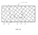
- FIG. 3C depicts another example surface feature 202 comprising an array of dimples or concavities 320 cast within the one-piece can combustor 102 according to another embodiment of the invention.
- the concavities 320 may have a diameter (D) 322 between about 7 to about 13 mm, a depth ( ⁇ ) between about 0.25 to about 0.5 mm, center to center row spacing (Sr) 324 between about 11 to about 20 mm, and center to center column spacing (Sc) 326 between about 11 to about 20 mm.
- the concavity row line 328 may be generally parallel to the center axis 130 of the one-piece can combustor 102.
- the concavity row line 328 may form any angle between about 0 and about 45 degrees with respect to the center axis 130 of the one-piece can combustor 102.
- FIG. 3D depicts another example surface feature 202 comprising an array of grooves 330 cast within the one-piece can combustor 102 according to another embodiment of the invention.
- the grooves 330 may have a circular depth profile with a radius of curvature ranging from about 1 to about 3 mm.
- the grooves may define a groove width 332 ranging from about 2 to about 8 mm, and a groove spacing 334 ranging from about 5 to about 13 mm.
- the groove center line 336 may be generally parallel to the center axis 130 of the one-piece can combustor 102.
- the groove center line 336 may form any angle between about 0 and about 45 degrees with respect to the center axis 130 of the one-piece can combustor 102.
- FIG. 3E depicts another example surface feature 202 comprising an array of fins 340 cast within the one-piece can combustor 102 according to another embodiment of the invention.
- the fins 340 may be about 0.5 to about 3 mm in height, and may have either a substantially flat or rounded fin top 342 surface.
- the fins 340 may also transition from the flat, lower regions, to the fin top 342 with a transition radius approximately 0.1 mm.
- the width 344 of the fins may be approximately 1 to approximately 7 mm, and the length 346 may be approximately 1 to approximately 7 mm.
- the fin row spacing 348 may be approximately 2 to approximately 8 mm, and the fin column spacing 350 may be approximately 2 to approximately 8 mm.
- the fins 340 may be defined with an alternating column offset 352 approximately 0 to approximately 5 mm.
- the fin row line 354 may be generally parallel to the center axis 130 of the one-piece can combustor 102. According to other example embodiments of the invention, the fin row line 354 may form any angle between about 0 and about 90 degrees with respect to the center axis 130 of the one-piece can combustor 102. Since the diameter of the one-piece can combustor varies from the head end 104 to the aft end 108, it will be appreciated that the fin length 346, the fin row spacing 348, and/or the fin column spacing 350 may vary as a function of the position along the body of the one-piece can combustor 102.
- FIG. 3F depicts another example surface feature 202 comprising an array of curved dunes 360 cast within the one-piece can combustor 102 according to another embodiment of the invention.
- the dunes 360 may generally have sand dune-type shape, ranging from about 0.5 to about 3 mm in height, and may have a substantially rounded top surface 362 having a top surface radius ranging from about 3 to about 7 mm.
- the dunes 360 may be further defined by a solid cylindrical cutout 366 on one side of the curved dune 360, with a cutout angle approximately 45 degrees with respect to the line normal to the surface, and with a diameter of the cutout approximately one-half the diameter 368 of the dune 360.
- the diameter 368 of the dune 360 may be approximately 7 to approximately 13 mm.
- the dune row period 370 may be approximately 11 to approximately 20 mm, and the dune column period 372 may be approximately 11 to approximately 20 mm.
- the dune row line 374 may be generally parallel to the center axis 130 of the one-piece can combustor 102. According to other example embodiments of the invention, the dune row line 374 may form any angle between about 0 and about 45 degrees with respect to the center axis 130 of the one-piece can combustor 102.
- the curved dunes 360 may be defined so that the cutout portions 364 are positioned towards the head end 104.
- the curved dunes 360 may be defined so that the cutout portions 364 are distributed substantially downwind with respect to direction of the discharge airflow 112 at each local surface feature. Furthermore, since the diameter of the one-piece can combustor 102 varies from the head end 104 to the aft end 108, it will be appreciated that the dune diameter 368, row spacing 370, and/or column spacing 372 may vary as a function of the position along the body of the one-piece can combustor 102.
- FIG. 4 depicts measured friction multiplier data for several example surface enhancement embodiments, according to example embodiments of the invention.
- the variable 'f' represents the coefficient of friction, sometimes called the friction factor, for any particular surface.
- the variable 'fsm' represents the coefficient of friction for a smooth surface without augmentation features or roughness.
- the ratio 'f/fsm' represents the augmentation of the coefficient of friction for a non-smooth surface, sometimes called the friction multiplier.
- 'Re' represents the Reynolds number of the backside convective flow, defined as the product of fluid bulk velocity times the characteristic length of the geometry, divided by the kinematic viscosity of the fluid. For example, FIG.
- FIG. 4 shows comparison data for a smooth surface (without surface enhancements), transverse turbulators (continuous turbulator rib, for example, with no rib end separation 310 and with angle 312 approximately 90 degrees), chevron patterns (as shown in FIG. 3B , with the angle 312 approximately 65 degrees), staggered sand dunes (as shown in FIG. 3F ) and in-line sand dunes (not shown).
- the variable “P” in FIG. 4 represents the "pitch” between the ribs, or the rib row separation 308.
- the variable “e” represents the rib height. Since the friction multiplier may correspond with a pressure drop in the airflow, the selection of a particular surface feature embodiment is typically based upon a trade-off between minimizing the friction while maximizing the heat removal efficiency.
- a one-piece can combustor such as 102 may be cast with surface features as a one-piece, unitary body.
- a method for manufacturing a one-piece can combustor such as 102 may include using expendable or non-expendable mold casting, die casting, semi-solid metal casting, centrifugal casting, continuous casting, etc.
- various materials used in manufacturing a one-piece can combustor such as 102 may include high temperature alloys such as Udimet 500, Haynes 188, or Haynes 230 for example.
- Block 502 is followed by block 504 , in which the one-piece can combustor, such as 102, may be mounted between a turbine combustor head end, such as 104, and an aft end, such as 108.
- an aft frame such as 122, including a sealing surface and mounting features 204, may be cast as part of the single piece can combustor 102, and the mounting features 204 may be designed to be secured to one more mounting brackets 126 attached to the frame of the turbine.
- the cap seal interface 128 at the head end 104 of the one-piece can combustor 102 may be mounted to the turbine using radial struts 124, for example.
- Block 504 is followed by block 506, in which the one-piece can combustor such as 102 may be surrounded by an impingement sleeve such as 114 to provide passage paths for discharge air such as 112 from the compressor to the surface of the one-piece can combustor 102, and to define a cooling annulus such as 116 around the one-piece can combustor 102 for directing air towards the head end such as 104 where it can be mixed with fuel in the plurality of fuel nozzles such as 106.
- an impingement sleeve such as 114 to provide passage paths for discharge air such as 112 from the compressor to the surface of the one-piece can combustor 102, and to define a cooling annulus such as 116 around the one-piece can combustor 102 for directing air towards the head end such as 104 where it can be mixed with fuel in the plurality of fuel nozzles such as 106.
- Block 506 is followed by block 508, in which the discharge air flowing within the cooling annulus such as 116 may interact with the surface of the one-piece can combustor such as 102, thereby removing heat from the one-piece can combustor 102.
- the heat removal process may be enhanced via the local interaction of the discharge air 112 with the surface features 202.
- a cast, one-piece can combustor such as 102 with one or more cast surface enhancements such as 202 may provide an advantage over conventional multiple-piece combustors.
- the minimization of the number of pieces can reduce the assembly time, reduce the number of seals required in connecting the combustor to the head end and aft end of the turbine, and eliminate or otherwise reduce the extra machining that would otherwise be required to define the surface features 202.
- At least one technical effect of at least one embodiment of the invention is that heat from the can combustor body may be transferred through the at least one surface feature to the air flow.
Landscapes
- Engineering & Computer Science (AREA)
- Chemical & Material Sciences (AREA)
- Combustion & Propulsion (AREA)
- Mechanical Engineering (AREA)
- General Engineering & Computer Science (AREA)
- Turbine Rotor Nozzle Sealing (AREA)
- Combustion Of Fluid Fuel (AREA)
Applications Claiming Priority (1)
| Application Number | Priority Date | Filing Date | Title |
|---|---|---|---|
| US12/372,246 US20100205972A1 (en) | 2009-02-17 | 2009-02-17 | One-piece can combustor with heat transfer surface enhacements |
Publications (1)
| Publication Number | Publication Date |
|---|---|
| EP2218968A2 true EP2218968A2 (de) | 2010-08-18 |
Family
ID=42174494
Family Applications (1)
| Application Number | Title | Priority Date | Filing Date |
|---|---|---|---|
| EP10153345A Withdrawn EP2218968A2 (de) | 2009-02-17 | 2010-02-11 | Einteiliges Flammrohr mit Verbesserungen der Wärmeübertragungsoberfläche |
Country Status (4)
| Country | Link |
|---|---|
| US (1) | US20100205972A1 (de) |
| EP (1) | EP2218968A2 (de) |
| JP (1) | JP2010190216A (de) |
| CN (1) | CN101893255A (de) |
Cited By (3)
| Publication number | Priority date | Publication date | Assignee | Title |
|---|---|---|---|---|
| EP2770258A3 (de) * | 2013-02-20 | 2015-07-15 | Mitsubishi Hitachi Power Systems, Ltd. | Gasturbinenbrennkammer mit Wärmeübertragungsvorrichtung |
| EP2792850A4 (de) * | 2011-12-15 | 2015-10-28 | Ihi Corp | Prallkühlungsmechanismus, turbinenschaufel und brennkammer |
| EP2538027A3 (de) * | 2011-06-21 | 2017-12-13 | General Electric Company | Verfahren und Systeme zur Übertragung von Wärme aus einem Übergangskanal |
Families Citing this family (19)
| Publication number | Priority date | Publication date | Assignee | Title |
|---|---|---|---|---|
| US8813501B2 (en) | 2011-01-03 | 2014-08-26 | General Electric Company | Combustor assemblies for use in turbine engines and methods of assembling same |
| US20120208141A1 (en) * | 2011-02-14 | 2012-08-16 | General Electric Company | Combustor |
| US9255484B2 (en) * | 2011-03-16 | 2016-02-09 | General Electric Company | Aft frame and method for cooling aft frame |
| US8966910B2 (en) * | 2011-06-21 | 2015-03-03 | General Electric Company | Methods and systems for cooling a transition nozzle |
| US9127552B2 (en) * | 2011-11-07 | 2015-09-08 | General Electric Company | Transition piece aft frame with fuel injection apertures |
| US20130180252A1 (en) * | 2012-01-18 | 2013-07-18 | General Electric Company | Combustor assembly with impingement sleeve holes and turbulators |
| US9145778B2 (en) | 2012-04-03 | 2015-09-29 | General Electric Company | Combustor with non-circular head end |
| US9506359B2 (en) | 2012-04-03 | 2016-11-29 | General Electric Company | Transition nozzle combustion system |
| US9121613B2 (en) * | 2012-06-05 | 2015-09-01 | General Electric Company | Combustor with brief quench zone with slots |
| US9546601B2 (en) * | 2012-11-20 | 2017-01-17 | General Electric Company | Clocked combustor can array |
| US20140366541A1 (en) * | 2013-06-14 | 2014-12-18 | General Electric Company | Systems and apparatus relating to fuel injection in gas turbines |
| KR101556532B1 (ko) * | 2014-01-16 | 2015-10-01 | 두산중공업 주식회사 | 냉각슬리브를 포함하는 라이너, 플로우슬리브 및 가스터빈연소기 |
| US10208604B2 (en) * | 2016-04-27 | 2019-02-19 | United Technologies Corporation | Cooling features with three dimensional chevron geometry |
| KR101906052B1 (ko) * | 2017-05-17 | 2018-10-08 | 두산중공업 주식회사 | 연소기 및 이를 포함하는 가스 터빈 |
| US20190072276A1 (en) * | 2017-09-06 | 2019-03-07 | United Technologies Corporation | Float wall combustor panels having heat transfer augmentation |
| KR102080566B1 (ko) * | 2018-01-03 | 2020-02-24 | 두산중공업 주식회사 | 연소기의 냉각구조와 이를 포함하는 연소기 및 가스터빈 |
| EP4047187A1 (de) * | 2021-02-18 | 2022-08-24 | Siemens Energy Global GmbH & Co. KG | Übergang mit unebener oberfläche |
| US20240151150A1 (en) | 2021-02-18 | 2024-05-09 | Siemens Energy Global GmbH & Co. KG | Transition with uneven surface |
| US12523173B2 (en) | 2024-05-10 | 2026-01-13 | Rtx Corporation | Supercharged combustor cooling using turbomachinery |
Citations (4)
| Publication number | Priority date | Publication date | Assignee | Title |
|---|---|---|---|---|
| US6098397A (en) | 1998-06-08 | 2000-08-08 | Caterpillar Inc. | Combustor for a low-emissions gas turbine engine |
| US6681578B1 (en) | 2002-11-22 | 2004-01-27 | General Electric Company | Combustor liner with ring turbulators and related method |
| US7082766B1 (en) | 2005-03-02 | 2006-08-01 | General Electric Company | One-piece can combustor |
| US7104067B2 (en) | 2002-10-24 | 2006-09-12 | General Electric Company | Combustor liner with inverted turbulators |
Family Cites Families (11)
| Publication number | Priority date | Publication date | Assignee | Title |
|---|---|---|---|---|
| JPH0752014B2 (ja) * | 1986-03-20 | 1995-06-05 | 株式会社日立製作所 | ガスタ−ビン燃焼器 |
| FR2724412B1 (fr) * | 1994-09-14 | 1996-10-25 | Snecma | Aube de turbomachine en materiau composite munie d'un joint d'etancheite et son procede de realisation |
| GB2328011A (en) * | 1997-08-05 | 1999-02-10 | Europ Gas Turbines Ltd | Combustor for gas or liquid fuelled turbine |
| US6021570A (en) * | 1997-11-20 | 2000-02-08 | Caterpillar Inc. | Annular one piece combustor liner |
| JP2003201863A (ja) * | 2001-10-29 | 2003-07-18 | Mitsubishi Heavy Ind Ltd | 燃焼器及びこれを備えたガスタービン |
| EP1426558A3 (de) * | 2002-11-22 | 2005-02-09 | General Electric Company | Gasturbinenübergangsstück mit geprägter Oberfläche, sowie Kühlverfahren für ein solches Gasturbinenübergangsstück |
| US7007482B2 (en) * | 2004-05-28 | 2006-03-07 | Power Systems Mfg., Llc | Combustion liner seal with heat transfer augmentation |
| US7373778B2 (en) * | 2004-08-26 | 2008-05-20 | General Electric Company | Combustor cooling with angled segmented surfaces |
| US7386980B2 (en) * | 2005-02-02 | 2008-06-17 | Power Systems Mfg., Llc | Combustion liner with enhanced heat transfer |
| US7540156B2 (en) * | 2005-11-21 | 2009-06-02 | General Electric Company | Combustion liner for gas turbine formed of cast nickel-based superalloy |
| US7757492B2 (en) * | 2007-05-18 | 2010-07-20 | General Electric Company | Method and apparatus to facilitate cooling turbine engines |
-
2009
- 2009-02-17 US US12/372,246 patent/US20100205972A1/en not_active Abandoned
-
2010
- 2010-02-11 EP EP10153345A patent/EP2218968A2/de not_active Withdrawn
- 2010-02-12 JP JP2010028379A patent/JP2010190216A/ja active Pending
- 2010-02-22 CN CN2010101352527A patent/CN101893255A/zh active Pending
Patent Citations (4)
| Publication number | Priority date | Publication date | Assignee | Title |
|---|---|---|---|---|
| US6098397A (en) | 1998-06-08 | 2000-08-08 | Caterpillar Inc. | Combustor for a low-emissions gas turbine engine |
| US7104067B2 (en) | 2002-10-24 | 2006-09-12 | General Electric Company | Combustor liner with inverted turbulators |
| US6681578B1 (en) | 2002-11-22 | 2004-01-27 | General Electric Company | Combustor liner with ring turbulators and related method |
| US7082766B1 (en) | 2005-03-02 | 2006-08-01 | General Electric Company | One-piece can combustor |
Cited By (5)
| Publication number | Priority date | Publication date | Assignee | Title |
|---|---|---|---|---|
| EP2538027A3 (de) * | 2011-06-21 | 2017-12-13 | General Electric Company | Verfahren und Systeme zur Übertragung von Wärme aus einem Übergangskanal |
| EP2792850A4 (de) * | 2011-12-15 | 2015-10-28 | Ihi Corp | Prallkühlungsmechanismus, turbinenschaufel und brennkammer |
| US9957812B2 (en) | 2011-12-15 | 2018-05-01 | Ihi Corporation | Impingement cooling mechanism, turbine blade and cumbustor |
| EP2770258A3 (de) * | 2013-02-20 | 2015-07-15 | Mitsubishi Hitachi Power Systems, Ltd. | Gasturbinenbrennkammer mit Wärmeübertragungsvorrichtung |
| US9435536B2 (en) | 2013-02-20 | 2016-09-06 | Mitsubishi Hitachi Power Systems, Ltd. | Gas turbine combustor equipped with heat-transfer device |
Also Published As
| Publication number | Publication date |
|---|---|
| CN101893255A (zh) | 2010-11-24 |
| US20100205972A1 (en) | 2010-08-19 |
| JP2010190216A (ja) | 2010-09-02 |
Similar Documents
| Publication | Publication Date | Title |
|---|---|---|
| EP2218968A2 (de) | Einteiliges Flammrohr mit Verbesserungen der Wärmeübertragungsoberfläche | |
| US7373778B2 (en) | Combustor cooling with angled segmented surfaces | |
| EP3006831B1 (de) | Gekühltes bauteil | |
| EP1400750B1 (de) | Doppelwandiges Brennkammer-Verbindungselement mit Kühlkanälen mit Vertiefungen | |
| US6640547B2 (en) | Effusion cooled transition duct with shaped cooling holes | |
| EP2481983B1 (de) | Turbulenz erzeugende Hinterkantenverkleidungsanordnung und Kühlungsverfahren für Gasturbinenbrennkammer | |
| EP3176372B1 (de) | Gekühltes bauteil einer turbomaschine | |
| US10927762B2 (en) | Cooled component | |
| US20050268615A1 (en) | Method and apparatus for cooling combustor liner and transition piece of a gas turbine | |
| EP2365198A2 (de) | Gezielte Kühlung der Gasturbinen- Leitschaufeln | |
| EP3099975B1 (de) | Gasturbinenbrennkammerverkleidungsplatte mit synergistischen kühlmerkmalen | |
| EP1561902B1 (de) | Turbinenschaufel mit Turbulatoren | |
| EP2532962A2 (de) | Brennermantel mit Turbulatoren | |
| EP3090208B1 (de) | Gasturbinenmotorwandanordnung mit verbesserter strömungsleitung | |
| CN115507387B (zh) | 用于燃气涡轮发动机的燃烧器 | |
| EP2957832B1 (de) | Wärmeleitende vorrichtung und gasturbinenbrennkammer damit | |
| EP1813868A2 (de) | Gasturbinenbrennkammerwandelemente | |
| CN115507390B (zh) | 用于燃气涡轮发动机的燃烧器 | |
| US10890327B2 (en) | Liner of a gas turbine engine combustor including dilution holes with airflow features | |
| CN115507386B (zh) | 用于燃气涡轮发动机的燃烧器 | |
| CN115507384A (zh) | 用于燃气涡轮发动机的燃烧器 | |
| WO2019002274A1 (en) | TURBOMACHINE COMPONENT AND METHOD FOR MANUFACTURING THE TURBOMACHINE COMPONENT | |
| CN115507383B (zh) | 用于燃气涡轮发动机的燃烧器 | |
| CN115507385A (zh) | 用于燃气涡轮发动机的燃烧器 | |
| US20200332664A1 (en) | Components for gas turbine engines |
Legal Events
| Date | Code | Title | Description |
|---|---|---|---|
| PUAI | Public reference made under article 153(3) epc to a published international application that has entered the european phase |
Free format text: ORIGINAL CODE: 0009012 |
|
| AK | Designated contracting states |
Kind code of ref document: A2 Designated state(s): AT BE BG CH CY CZ DE DK EE ES FI FR GB GR HR HU IE IS IT LI LT LU LV MC MK MT NL NO PL PT RO SE SI SK SM TR |
|
| STAA | Information on the status of an ep patent application or granted ep patent |
Free format text: STATUS: THE APPLICATION IS DEEMED TO BE WITHDRAWN |
|
| 18D | Application deemed to be withdrawn |
Effective date: 20150901 |