EP2218905A1 - Injector and method for injecting fluid - Google Patents
Injector and method for injecting fluid Download PDFInfo
- Publication number
- EP2218905A1 EP2218905A1 EP09002221A EP09002221A EP2218905A1 EP 2218905 A1 EP2218905 A1 EP 2218905A1 EP 09002221 A EP09002221 A EP 09002221A EP 09002221 A EP09002221 A EP 09002221A EP 2218905 A1 EP2218905 A1 EP 2218905A1
- Authority
- EP
- European Patent Office
- Prior art keywords
- flow
- closing element
- guiding surface
- fluid
- cartridge
- Prior art date
- Legal status (The legal status is an assumption and is not a legal conclusion. Google has not performed a legal analysis and makes no representation as to the accuracy of the status listed.)
- Granted
Links
Images


Classifications
-
- F—MECHANICAL ENGINEERING; LIGHTING; HEATING; WEAPONS; BLASTING
- F02—COMBUSTION ENGINES; HOT-GAS OR COMBUSTION-PRODUCT ENGINE PLANTS
- F02M—SUPPLYING COMBUSTION ENGINES IN GENERAL WITH COMBUSTIBLE MIXTURES OR CONSTITUENTS THEREOF
- F02M61/00—Fuel-injectors not provided for in groups F02M39/00 - F02M57/00 or F02M67/00
- F02M61/04—Fuel-injectors not provided for in groups F02M39/00 - F02M57/00 or F02M67/00 having valves, e.g. having a plurality of valves in series
- F02M61/08—Fuel-injectors not provided for in groups F02M39/00 - F02M57/00 or F02M67/00 having valves, e.g. having a plurality of valves in series the valves opening in direction of fuel flow
-
- F—MECHANICAL ENGINEERING; LIGHTING; HEATING; WEAPONS; BLASTING
- F02—COMBUSTION ENGINES; HOT-GAS OR COMBUSTION-PRODUCT ENGINE PLANTS
- F02M—SUPPLYING COMBUSTION ENGINES IN GENERAL WITH COMBUSTIBLE MIXTURES OR CONSTITUENTS THEREOF
- F02M61/00—Fuel-injectors not provided for in groups F02M39/00 - F02M57/00 or F02M67/00
- F02M61/16—Details not provided for in, or of interest apart from, the apparatus of groups F02M61/02 - F02M61/14
- F02M61/18—Injection nozzles, e.g. having valve seats; Details of valve member seated ends, not otherwise provided for
- F02M61/1873—Valve seats or member ends having circumferential grooves or ridges, e.g. toroidal
-
- F—MECHANICAL ENGINEERING; LIGHTING; HEATING; WEAPONS; BLASTING
- F02—COMBUSTION ENGINES; HOT-GAS OR COMBUSTION-PRODUCT ENGINE PLANTS
- F02M—SUPPLYING COMBUSTION ENGINES IN GENERAL WITH COMBUSTIBLE MIXTURES OR CONSTITUENTS THEREOF
- F02M61/00—Fuel-injectors not provided for in groups F02M39/00 - F02M57/00 or F02M67/00
- F02M61/16—Details not provided for in, or of interest apart from, the apparatus of groups F02M61/02 - F02M61/14
- F02M61/18—Injection nozzles, e.g. having valve seats; Details of valve member seated ends, not otherwise provided for
- F02M61/1893—Details of valve member ends not covered by groups F02M61/1866 - F02M61/188
Definitions
- the invention relates to an injector and a method for injecting fluid and relates particularly to an injector and a method for injecting fuel into an internal combustion engine.
- spray targeting performance is fundamental for a mixture preparation in a spark plug area.
- evaporation of gasoline provided in a first of multiple successive injections in a high temperature environment induces an upward flow field perturbing the successive injections and changing a direction of a spray. This leads to fluctuations of a spray cone angle. Engine misfire and increase of emissions may occur as a consequence.
- the object of the invention is to provide an injector and a method for injecting fluid that allows for a stable and dependable spray pattern.
- the invention is characterized by an injector comprising a closing element, a deflection element and a cartridge.
- the closing element comprises a conical flow guiding surface downstream of a contact area.
- the flow guiding surface of the closing element extends to an outer edge of the closing element.
- the deflection element is arranged at the flow guiding surface of the closing element.
- the deflection element is dimensioned to deflect a fluid flow only during a first time period directly following a beginning of each opening phase of the injector during which the fluid flow is guided by the flow guiding surface of the closing element from a first flow direction upstream the deflection element to a second flow direction differing from the first flow direction such that the fluid is injected in the second flow direction.
- the cartridge comprises a flow guiding surface.
- the flow guiding surface of the cartridge comprises a valve seat and is arranged adjacent to a downstream end of the cartridge in an angle with respect to a longitudinal axis of the cartridge greater than that of the flow guiding surface of the closing element.
- the contact area of the closing element is arranged for being in sealing contact with the valve seat in a closed position of the closing element.
- the flow guiding surface of the cartridge is arranged for taking over a guidance of the fluid flow from the flow guiding surface of the closing element during a second time period directly following the first time period such that the fluid is injected in a third flow direction differing from the second flow direction.
- An advantage is that with such injector a stable and dependable spray pattern may be created that is conical or that is broader at the beginning during the first time period than later during the second time period, that is, the spray pattern does not have a collapsed form. This enables for a low interaction of fluid when injected in rapid succession. This allows for a low emission and low consumption operation of an internal combustion engine when fuel is injected into the internal combustion engine, particularly during stratified operation.
- the deflection element is formed as an annular deflection element to allow for a uniform distribution of the fluid without interruptions 360 degrees around the longitudinal axis of the cartridge.
- the deflection element is dimensioned thick enough to deflect the fluid flow from the first to the second flow direction when the fluid flow is guided by the flow guiding surface of the closing element.
- the deflection element is further dimensioned thin enough to not deflect the fluid flow when the fluid flow is guided by the flow guiding surface of the cartridge.
- the third flow direction is therefore essentially determined by the flow guiding surface of the cartridge, not by the deflection element.
- the fluid flow essentially is represented by a core flow of all fluid passing a gap between the valve seat of the cartridge and the contact area of the closing element. The deflection or non-deflection of the fluid flow therefore respectively involves the deflection or non-deflection of the core flow.
- a thickness of the deflection element amounts to 0.2 to 2 micrometers.
- a distance of an upstream edge of the deflection element from the outer edge of the closing element amounts to 2 to 20 micrometers.
- the deflection element is formed as a coating.
- the deflection element is formed as a plastic deformation of the closing element.
- Such deflection element may be particularly robust and durable.
- a seat distance between the contact area seated on the valve seat and the outer edge of the closing element amounts to 70 to 160 micrometers. With this seat distance sufficient space is available downstream the contact area and the valve seat for the fluid flow to be guided first by the flow guiding surface of the closing element and second by the flow guiding surface of the cartridge and to enable the take over of the guiding.
- a gap size of a gap between the cartridge and the closing element at the downstream end of the cartridge in the closed position of the closing element amounts to 3 to 8 micrometers.
- the invention is characterized by a method for injecting fluid.
- the method comprises guiding a fluid flow with a conical flow guiding surface of a closing element of an injector and deflecting the fluid flow with a deflection element arranged at the flow guiding surface of the closing element from a first flow direction upstream the deflection element to a second flow direction differing from the first flow direction during a first time period directly following a beginning of an opening phase of the injector and injecting the fluid in the second flow direction.
- the method further comprises taking over a guidance of the fluid flow from the flow guiding surface of the closing element and guiding the fluid flow with a flow guiding surface of a cartridge arranged adjacent to a downstream end of the cartridge during a second time period during the opening phase and/or open state of the injector following the first time period and injecting the fluid in a third flow direction differing from the second flow direction.
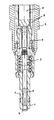
- Figure 1 shows an injector for injecting a fluid.
- the injector is designed for injecting fuel into a cylinder of an internal combustion engine of, for example, a vehicle and particularly an automobile.
- the injector comprises an external tube 1, an internal tube 2 and a valve cap 3.
- the fluid passes through an annular cavity between the external tube 1 and the internal tube 2 and through the valve cap 3.
- the injector further comprises a cartridge 4 with a recess 5 in which a valve needle 6 is arranged axially movable.
- the valve needle 6 comprises a closing element 7 at its downstream end arranged for closing the injector in its closed position inhibiting a fluid flow and for allowing the fluid flow otherwise.
- the injector further comprises a lifting device with an actuator 8 for moving the valve needle 6 in axial direction for opening and closing the injector.
- the actuator 8 preferably is a piezo actuator.
- the actuator 8 may alternatively be, for example, a solenoid actuator.
- a lift generated by the lifting device depends on an axial elongation of the actuator 8 which is dependent on an electric control signal.
- the lifting device is mechanically coupled with the valve needle 6 and cooperates with the valve needle 6 such that at least part of the lift generated by the lifting device is transferred to the valve needle 6 moving the closing element 7 in its closed position or in an open position.
- a closing force is provided to the valve needle 6 by a valve spring 9 which is preloaded during assembly of the injector.
- the injector may be designed differently.
- Figure 2 shows the closing element 7 and figures 3 and 4 show part of a downstream portion of the cartridge 4 and the closing element 7.
- the recess 5 of the cartridge 4 widens conically in the downstream portion of the cartridge 4 up to an edge 10 of the cartridge 4 which represents a downstream end of the cartridge 4.
- a preferably conical inner surface directly upstream the edge 10 of the cartridge 4 forms a flow guiding surface 11 of the cartridge 4.
- This flow guiding surface 11 of the cartridge 4 comprises or forms a valve seat 12.
- the closing element 7 comprises a contact area 13. In the closed position of the closing element 7 the contact area 13 is sealingly seated on the valve seat 12 inhibiting the fluid flow.
- the contact area 13 preferably is designed as a rounded portion allowing for a ring-shaped contact line in the closed position of the closing element 7.
- the closing element 7 widens conically downstream the contact area 13 up to an outer edge 14 of the closing element 7.
- a conical surface directly upstream the outer edge 14 of the closing element 7 forms a flow guiding surface 15 of the closing element 7.
- An angle of the flow guiding surface 11 of the cartridge 4 with respect to a longitudinal axis of the injector preferably is slightly larger than that of the flow guiding surface 15 of the closing element 7.
- the flow guiding surface 11 of the cartridge 4 and the flow guiding surface 15 of the closing element 7 diverge from the valve seat 12 and contact area 13 in a direction of the fluid flow.
- the angles differ by less than ten degrees and differ even more preferably by less than five degrees.
- the closing element 7 comprises a deflection element 16.
- the deflection element 16 is arranged on the flow guiding surface 15 of the closing element 7.
- the deflection element 16 is formed as an annular deflection element 16 coaxial with respect to a longitudinal axis of the closing element 7.
- the deflection element 16 is continuous without interruptions.
- the deflection element 16 is formed as a coating on the closing element 7 as shown in figure 2 in the left and in the middle detail view or as a plastic deformation as shown in figure 2 in the right detail view. It is considered sufficient to apply the coating only on the flow guiding surface 15 of the closing element 7 as shown in the left detail view of figure 2 .
- the deflection element 16 is dimensioned such that the fluid flow is deflected by the deflection element 16 from a first flow direction FD1 upstream the deflection element 16 to a second flow direction FD2 different from the first flow direction FD1 only during a first time period TP1 directly following a beginning of an opening phase of the injector.
- TP1 first time period directly following a beginning of an opening phase of the injector.
- the fluid flow directly prior to injection is guided by the flow guiding surface 15 of the closing element 7 and the deflection element 16. This is shown in figure 3 .
- the fluid is injected in the second flow direction FD2 dependent on the dimensions of the deflection element 16.
- An angle of the second flow direction FD2 with respect to the longitudinal axis of the injector is greater than that of the first flow direction FD1. Without the deflection element 16 the fluid would be injected essentially in the first flow direction FD1 dependent on the angle of the flow guiding surface 15 of the closing element 7.
- a second time period TP2 following the first time period TP1 guidance of the fluid flow is taken over from the flow guiding surface 15 of the closing element 7 by the flow guiding surface 11 of the cartridge 4.
- the fluid flow is no longer effectively deflected by the deflection element 16 and the fluid is injected in a third flow direction FD3 different from the second flow direction FD2 depending on the angle of the flow guiding surface 11 of the cartridge 4. Due to only slight differences in the angle of the flow guiding surface 11 of the cartridge 4 from the angle of the flow guiding surface 15 of the closing element 7 the third flow direction FD3 may be slightly different from the first flow direction FD1.
- a sudden opening of the injector that is lifting the closing element 7 from its closed position on the valve seat 12 to an open position, generates a water hammer effect.
- An intensity of the water hammer effect increases with a pressure of the fluid.
- the water hammer effect is responsible for a pressure drop in a primary phase of a hydraulic injection of the fluid. In this primary phase the fluid may be injected with poor momentum compared to a later secondary phase of the hydraulic injection.
- a thickness T of the deflection element 16 is dimensioned such that the fluid flow interacts with the deflection element 16 effectively in the primary phase of the opening of the injector. The interaction decreases in the secondary phase.
- the deflection element 16 is essentially effective when the fluid flow has poor momentum because of the pressure drop due to the water hammer effect and when the fluid flow is guided by the flow guiding surface 15 of the closing element 7.
- the thickness T of the deflection element 16 must be small enough in order to reduce its contribution to a spray angle when in the secondary phase a stabilized lift of the closing element 7 is reached and the flow guiding surface 11 of the cartridge 4 acts as guiding surface for the fluid flow.
- An influence of the deflection element 16 preferably is negligable during the secondary phase.
- the change of guidance from the flow guiding surface 15 of the closing element 7 to the flow guiding surface 11 of the cartridge 4 is based on an increase of momentum of the fluid flow during the opening phase.
- the first time period TD1 essentially corresponds to the primary phase
- the second time period TD2 essentially corresponds to the secondary phase.
- Figure 5 shows a resulting spray pattern 17.
- the spray pattern 17 has a widened form instead of a collapsed form 18 that would result without the deflection element 16 because of the low momentum of the fluid during the primary phase and the small angle of the flow guiding surface 15 of the closing element 7 with respect to the longitudinal axis of the injector.
- the thickness T of the deflection element 16 preferably amounts to about 0.2 to 2 micrometers.
- the distance D amounts to about 5 to 20 micrometers when the deflection element 16 is formed as the coating.
- the coating is applied over the full distance D. This enables a robust coating and a simple and cost effective manufacturing of the injector.
- the distance D amounts to about 2 to 5 micrometers when the deflection element 16 is formed as the plastic deformation.
- a seat distance S of the valve seat 12 and the contact area 13 from the outer edge 14 of the closing element 7 in the closed position of the closing element 7 preferably amounts to about 70 to 160 micrometers.
- a resulting gap size G between the edge 10 of the cartridge 4 and the flow guiding surface 15 of the closing element 7 in the closed position of the closing element 7 preferably amounts to about 3 to 8 micrometers.
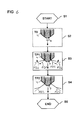
- Figure 6 shows a flow chart of a method for injecting fluid.
- the method is performed by the injector.
- the method begins with a step S1.
- the injector and particularly the actuator 8 is provided with the control signal for opening the injector.
- the closing element 7 begins to lift off of the valve seat 12 of the cartridge 4 and the fluid begins to flow through the gap between the contact area 13 and the valve seat 12.
- the point of time T0 represents the beginning of the opening phase of the injector.
- a step S3 within the first time period TP1, the fluid flow is guided by the flow guiding surface 15 of the closing element 7 and is deflected by the deflection element 16 and is injected in the second flow direction FD2 as explained above.
- a step S4 within the second time period TP2, the guidance of the fluid flow is taken over from the flow guiding surface 15 of the closing element 7 by the flow guiding surface 11 of the cartridge 4 and the fluid flow is guided by the flow guiding surface 11 of the cartridge and is injected in the third flow direction FD3 as explained above.
- the method ends in a step S5.
- the method is performed with each injection, that is with each opening phase of the injector.
Landscapes
- Engineering & Computer Science (AREA)
- Chemical & Material Sciences (AREA)
- Combustion & Propulsion (AREA)
- Mechanical Engineering (AREA)
- General Engineering & Computer Science (AREA)
- Fuel-Injection Apparatus (AREA)
Abstract
Description
- The invention relates to an injector and a method for injecting fluid and relates particularly to an injector and a method for injecting fuel into an internal combustion engine.
- In a stratified operation mode, spray targeting performance is fundamental for a mixture preparation in a spark plug area. However, evaporation of gasoline provided in a first of multiple successive injections in a high temperature environment induces an upward flow field perturbing the successive injections and changing a direction of a spray. This leads to fluctuations of a spray cone angle. Engine misfire and increase of emissions may occur as a consequence.
- The object of the invention is to provide an injector and a method for injecting fluid that allows for a stable and dependable spray pattern.
- This object is achieved with the features of the independent claims. Preferred embodiments are characterized in the dependent claims.
- According to a first aspect the invention is characterized by an injector comprising a closing element, a deflection element and a cartridge. The closing element comprises a conical flow guiding surface downstream of a contact area. The flow guiding surface of the closing element extends to an outer edge of the closing element. The deflection element is arranged at the flow guiding surface of the closing element. The deflection element is dimensioned to deflect a fluid flow only during a first time period directly following a beginning of each opening phase of the injector during which the fluid flow is guided by the flow guiding surface of the closing element from a first flow direction upstream the deflection element to a second flow direction differing from the first flow direction such that the fluid is injected in the second flow direction. The cartridge comprises a flow guiding surface. The flow guiding surface of the cartridge comprises a valve seat and is arranged adjacent to a downstream end of the cartridge in an angle with respect to a longitudinal axis of the cartridge greater than that of the flow guiding surface of the closing element. The contact area of the closing element is arranged for being in sealing contact with the valve seat in a closed position of the closing element. The flow guiding surface of the cartridge is arranged for taking over a guidance of the fluid flow from the flow guiding surface of the closing element during a second time period directly following the first time period such that the fluid is injected in a third flow direction differing from the second flow direction.
- An advantage is that with such injector a stable and dependable spray pattern may be created that is conical or that is broader at the beginning during the first time period than later during the second time period, that is, the spray pattern does not have a collapsed form. This enables for a low interaction of fluid when injected in rapid succession. This allows for a low emission and low consumption operation of an internal combustion engine when fuel is injected into the internal combustion engine, particularly during stratified operation.
- Preferably, the deflection element is formed as an annular deflection element to allow for a uniform distribution of the fluid without interruptions 360 degrees around the longitudinal axis of the cartridge. The deflection element is dimensioned thick enough to deflect the fluid flow from the first to the second flow direction when the fluid flow is guided by the flow guiding surface of the closing element. The deflection element is further dimensioned thin enough to not deflect the fluid flow when the fluid flow is guided by the flow guiding surface of the cartridge. The third flow direction is therefore essentially determined by the flow guiding surface of the cartridge, not by the deflection element. The fluid flow essentially is represented by a core flow of all fluid passing a gap between the valve seat of the cartridge and the contact area of the closing element. The deflection or non-deflection of the fluid flow therefore respectively involves the deflection or non-deflection of the core flow.
- According to a preferred embodiment, a thickness of the deflection element amounts to 0.2 to 2 micrometers. By this, the deflection element is thick enough to deflect the fluid flow from the first to the second flow direction when the fluid flow is guided by the flow guiding surface of the closing element and is thin enough to not deflect the fluid flow when the fluid flow is guided by the flow guiding surface of the cartridge.
- According to a further preferred embodiment, a distance of an upstream edge of the deflection element from the outer edge of the closing element amounts to 2 to 20 micrometers. By this, the deflection element can cover an area on the flow guiding surface of the closing element that is big enough to be durable and robust to tolerate high pressure pulses during operation. Further, it is small enough to not affect the sealing contact between the cartridge and the closing element and to not being destroyed by the repeated opening and closing operation of the injector. The deflection element and thus the injector may therefore be robust and dependable.
- According to a further preferred embodiment, the deflection element is formed as a coating. An advantage is that this is simple and inexpensive. Further, a coating can be applied very precisely, particularly with respect to its thickness, and may thus allow for a dependable spray pattern.
- According to a further preferred embodiment, the deflection element is formed as a plastic deformation of the closing element. Such deflection element may be particularly robust and durable.
- According to a further preferred embodiment, a seat distance between the contact area seated on the valve seat and the outer edge of the closing element amounts to 70 to 160 micrometers. With this seat distance sufficient space is available downstream the contact area and the valve seat for the fluid flow to be guided first by the flow guiding surface of the closing element and second by the flow guiding surface of the cartridge and to enable the take over of the guiding.
- According to a further preferred embodiment, a gap size of a gap between the cartridge and the closing element at the downstream end of the cartridge in the closed position of the closing element amounts to 3 to 8 micrometers. By this, only few space is available for a build up of combustion residues that could affect the spray pattern. Further, the take over of the guiding from the flow guiding surface of the closing element to the flow guiding surface of the cartridge is supported. The resulting spray pattern may thus be stable and dependable.
- According to a second aspect the invention is characterized by a method for injecting fluid. The method comprises guiding a fluid flow with a conical flow guiding surface of a closing element of an injector and deflecting the fluid flow with a deflection element arranged at the flow guiding surface of the closing element from a first flow direction upstream the deflection element to a second flow direction differing from the first flow direction during a first time period directly following a beginning of an opening phase of the injector and injecting the fluid in the second flow direction. The method further comprises taking over a guidance of the fluid flow from the flow guiding surface of the closing element and guiding the fluid flow with a flow guiding surface of a cartridge arranged adjacent to a downstream end of the cartridge during a second time period during the opening phase and/or open state of the injector following the first time period and injecting the fluid in a third flow direction differing from the second flow direction.
- The advantages of the second aspect of the invention essentially are the same as the advantages of the first aspect of the invention.
- In the following, embodiments of the invention are illustrated with reference to the schematic drawings.
- The figures are illustrating:
-
FIG. 1 , an injector, -
FIG. 2 , a closing element, -
FIG. 3 , a downstream portion of a cartridge and the closing element at a first point of time, -
FIG. 4 , a downstream portion of the cartridge and the closing element at a second point of time, -
FIG. 5 , a resulting spray pattern and -
FIG. 6 , a flow chart. - Elements of same construction or function are provided with the same reference signs throughout all figures.
-
Figure 1 shows an injector for injecting a fluid. Particularly, the injector is designed for injecting fuel into a cylinder of an internal combustion engine of, for example, a vehicle and particularly an automobile. The injector comprises anexternal tube 1, aninternal tube 2 and a valve cap 3. The fluid passes through an annular cavity between theexternal tube 1 and theinternal tube 2 and through the valve cap 3. The injector further comprises acartridge 4 with arecess 5 in which avalve needle 6 is arranged axially movable. Thevalve needle 6 comprises aclosing element 7 at its downstream end arranged for closing the injector in its closed position inhibiting a fluid flow and for allowing the fluid flow otherwise. The injector further comprises a lifting device with an actuator 8 for moving thevalve needle 6 in axial direction for opening and closing the injector. The actuator 8 preferably is a piezo actuator. However, the actuator 8 may alternatively be, for example, a solenoid actuator. In case of the actuator 8 being the piezo actuator, a lift generated by the lifting device depends on an axial elongation of the actuator 8 which is dependent on an electric control signal. The lifting device is mechanically coupled with thevalve needle 6 and cooperates with thevalve needle 6 such that at least part of the lift generated by the lifting device is transferred to thevalve needle 6 moving theclosing element 7 in its closed position or in an open position. Further, a closing force is provided to thevalve needle 6 by a valve spring 9 which is preloaded during assembly of the injector. However, the injector may be designed differently. -
Figure 2 shows theclosing element 7 andfigures 3 and4 show part of a downstream portion of thecartridge 4 and theclosing element 7. Therecess 5 of thecartridge 4 widens conically in the downstream portion of thecartridge 4 up to anedge 10 of thecartridge 4 which represents a downstream end of thecartridge 4. A preferably conical inner surface directly upstream theedge 10 of thecartridge 4 forms aflow guiding surface 11 of thecartridge 4. Thisflow guiding surface 11 of thecartridge 4 comprises or forms avalve seat 12. Theclosing element 7 comprises acontact area 13. In the closed position of theclosing element 7 thecontact area 13 is sealingly seated on thevalve seat 12 inhibiting the fluid flow. Thecontact area 13 preferably is designed as a rounded portion allowing for a ring-shaped contact line in the closed position of theclosing element 7. Theclosing element 7 widens conically downstream thecontact area 13 up to anouter edge 14 of theclosing element 7. A conical surface directly upstream theouter edge 14 of theclosing element 7 forms aflow guiding surface 15 of theclosing element 7. An angle of theflow guiding surface 11 of thecartridge 4 with respect to a longitudinal axis of the injector preferably is slightly larger than that of theflow guiding surface 15 of theclosing element 7. By this, theflow guiding surface 11 of thecartridge 4 and theflow guiding surface 15 of theclosing element 7 diverge from thevalve seat 12 andcontact area 13 in a direction of the fluid flow. Preferably, the angles differ by less than ten degrees and differ even more preferably by less than five degrees. - The
closing element 7 comprises adeflection element 16. Thedeflection element 16 is arranged on theflow guiding surface 15 of theclosing element 7. Preferably, thedeflection element 16 is formed as anannular deflection element 16 coaxial with respect to a longitudinal axis of theclosing element 7. Thus, preferably, thedeflection element 16 is continuous without interruptions. Preferably, thedeflection element 16 is formed as a coating on theclosing element 7 as shown infigure 2 in the left and in the middle detail view or as a plastic deformation as shown infigure 2 in the right detail view. It is considered sufficient to apply the coating only on theflow guiding surface 15 of theclosing element 7 as shown in the left detail view offigure 2 . However, it may be advantageous to apply the coating also to a part of theclosing element 7 downstream theouter edge 14 of theclosing element 7. This may be easier to manufacture and may thus be more cost effective. - The
deflection element 16 is dimensioned such that the fluid flow is deflected by thedeflection element 16 from a first flow direction FD1 upstream thedeflection element 16 to a second flow direction FD2 different from the first flow direction FD1 only during a first time period TP1 directly following a beginning of an opening phase of the injector. During this first time period TP1 the fluid flow directly prior to injection is guided by theflow guiding surface 15 of theclosing element 7 and thedeflection element 16. This is shown infigure 3 . As a result, the fluid is injected in the second flow direction FD2 dependent on the dimensions of thedeflection element 16. An angle of the second flow direction FD2 with respect to the longitudinal axis of the injector is greater than that of the first flow direction FD1. Without thedeflection element 16 the fluid would be injected essentially in the first flow direction FD1 dependent on the angle of theflow guiding surface 15 of theclosing element 7. - During a second time period TP2 following the first time period TP1 guidance of the fluid flow is taken over from the
flow guiding surface 15 of theclosing element 7 by theflow guiding surface 11 of thecartridge 4. By this, the fluid flow is no longer effectively deflected by thedeflection element 16 and the fluid is injected in a third flow direction FD3 different from the second flow direction FD2 depending on the angle of theflow guiding surface 11 of thecartridge 4. Due to only slight differences in the angle of theflow guiding surface 11 of thecartridge 4 from the angle of theflow guiding surface 15 of theclosing element 7 the third flow direction FD3 may be slightly different from the first flow direction FD1. - A sudden opening of the injector, that is lifting the
closing element 7 from its closed position on thevalve seat 12 to an open position, generates a water hammer effect. An intensity of the water hammer effect increases with a pressure of the fluid. The water hammer effect is responsible for a pressure drop in a primary phase of a hydraulic injection of the fluid. In this primary phase the fluid may be injected with poor momentum compared to a later secondary phase of the hydraulic injection. - A thickness T of the
deflection element 16 is dimensioned such that the fluid flow interacts with thedeflection element 16 effectively in the primary phase of the opening of the injector. The interaction decreases in the secondary phase. In other words: Thedeflection element 16 is essentially effective when the fluid flow has poor momentum because of the pressure drop due to the water hammer effect and when the fluid flow is guided by theflow guiding surface 15 of theclosing element 7. The thickness T of thedeflection element 16 must be small enough in order to reduce its contribution to a spray angle when in the secondary phase a stabilized lift of theclosing element 7 is reached and theflow guiding surface 11 of thecartridge 4 acts as guiding surface for the fluid flow. In other words: An influence of thedeflection element 16 preferably is negligable during the secondary phase. The change of guidance from theflow guiding surface 15 of theclosing element 7 to theflow guiding surface 11 of thecartridge 4 is based on an increase of momentum of the fluid flow during the opening phase. The first time period TD1 essentially corresponds to the primary phase, the second time period TD2 essentially corresponds to the secondary phase. -
Figure 5 shows a resultingspray pattern 17. Thespray pattern 17 has a widened form instead of acollapsed form 18 that would result without thedeflection element 16 because of the low momentum of the fluid during the primary phase and the small angle of theflow guiding surface 15 of theclosing element 7 with respect to the longitudinal axis of the injector. - The thickness T of the
deflection element 16 preferably amounts to about 0.2 to 2 micrometers. A location of an upstream edge of thedeflection element 16 on theflow guiding surface 15 of theclosing element 7 with respect to theouter edge 14 of theclosing element 7, that is a distance D of this upstream edge of thedeflection element 16 from theouter edge 14 of theclosing element 7, preferably amounts to about 2 to 20 micrometers. Preferably, the distance D amounts to about 5 to 20 micrometers when thedeflection element 16 is formed as the coating. Preferably, the coating is applied over the full distance D. This enables a robust coating and a simple and cost effective manufacturing of the injector. Preferably, the distance D amounts to about 2 to 5 micrometers when thedeflection element 16 is formed as the plastic deformation. - A seat distance S of the
valve seat 12 and thecontact area 13 from theouter edge 14 of theclosing element 7 in the closed position of theclosing element 7 preferably amounts to about 70 to 160 micrometers. A resulting gap size G between theedge 10 of thecartridge 4 and theflow guiding surface 15 of theclosing element 7 in the closed position of theclosing element 7 preferably amounts to about 3 to 8 micrometers. -
Figure 6 shows a flow chart of a method for injecting fluid. The method is performed by the injector. The method begins with a step S1. In a step S2 the injector and particularly the actuator 8 is provided with the control signal for opening the injector. At a point of time T0 theclosing element 7 begins to lift off of thevalve seat 12 of thecartridge 4 and the fluid begins to flow through the gap between thecontact area 13 and thevalve seat 12. The point of time T0 represents the beginning of the opening phase of the injector. - In a step S3, within the first time period TP1, the fluid flow is guided by the
flow guiding surface 15 of theclosing element 7 and is deflected by thedeflection element 16 and is injected in the second flow direction FD2 as explained above. In a step S4, within the second time period TP2, the guidance of the fluid flow is taken over from theflow guiding surface 15 of theclosing element 7 by theflow guiding surface 11 of thecartridge 4 and the fluid flow is guided by theflow guiding surface 11 of the cartridge and is injected in the third flow direction FD3 as explained above. The method ends in a step S5. Preferably, the method is performed with each injection, that is with each opening phase of the injector.
Claims (8)
- Injector comprising- a closing element (7) comprising a conical flow guiding surface (15) downstream of a contact area (13), the flow guiding surface (15) of the closing element (7) extending to an outer edge (14) of the closing element (7),- a deflection element (16) arranged at the flow guiding surface (15) of the closing element (7), the deflection element (16) being dimensioned to deflect a fluid flow only during a first time period (TP1) directly following a beginning of each opening phase of the injector during which the fluid flow is guided by the flow guiding surface (15) of the closing element (7) from a first flow direction (FD1) upstream the deflection element (16) to a second flow direction (FD2) differing from the first flow direction (FD1) such that the fluid is injected in the second flow direction (FD2), and- a cartridge (4) with a flow guiding surface (11), the flow guiding surface (11) of the cartridge (4) comprising a valve seat (12) and being arranged adjacent to a downstream end of the cartridge (4) in an angle with respect to a longitudinal axis of the cartridge (4) greater than that of the flow guiding surface (15) of the closing element (7), the contact area (13) of the closing element (7) being arranged for being in sealing contact with the valve seat (12) in a closed position of the closing element (7) and the flow guiding surface (11) of the cartridge (4) being arranged for taking over a guidance of the fluid flow from the flow guiding surface (15) of the closing element (7) during a second time period (TP2) directly following the first time period (TP1) such that the fluid is injected in a third flow direction (FD3) differing from the second flow direction (FD2).
- Injector according to claim 1, wherein a thickness (T) of the deflection element (16) amounts to 0.2 to 2 micrometers.
- Injector according to any one of claims 1 and 2, wherein a distance (D) of an upstream edge of the deflection element (16) from the outer edge (14) of the closing element (7) amounts to 2 to 20 micrometers.
- Injector according to any one of claims 1 to 3, wherein the deflection element (16) is formed as a coating.
- Injector according to any one of claims 1 to 3, wherein the deflection element (16) is formed as a plastic deformation of the closing element (7).
- Injector according to any one of claims 1 to 5, wherein a seat distance (S) between the contact area (13) seated on the valve seat (12) and the outer edge (14) of the closing element (7) amounts to 70 to 160 micrometers.
- Injector according to any one of claims 1 to 6, wherein a gap size (G) of a gap between the cartridge (4) and the closing element (7) at the downstream end of the cartridge (4) in the closed position of the closing element (7) amounts to 3 to 8 micrometers.
- Method for injecting fluid comprising- guiding a fluid flow with a conical flow guiding surface (15) of a closing element (7) of an injector and deflecting the fluid flow with a deflection element (16) arranged at the flow guiding surface (15) of the closing element (7) from a first flow direction (FD1) upstream the deflection element (16) to a second flow direction (FD2) differing from the first flow direction (FD1) during a first time period (TP1) directly following a beginning of an opening phase of the injector and injecting the fluid in the second flow direction (FD2) and- taking over a guidance of the fluid flow from the flow guiding surface (15) of the closing element (7) and guiding the fluid flow with a flow guiding surface (11) of a cartridge (4) arranged adjacent to a downstream end of the cartridge (4) during a second time period (TP2) during the opening phase and/or open state of the injector following the first time period (TP1) and injecting the fluid in a third flow direction (FD3) differing from the second flow direction (FD2).
Priority Applications (1)
| Application Number | Priority Date | Filing Date | Title |
|---|---|---|---|
| EP20090002221 EP2218905B1 (en) | 2009-02-17 | 2009-02-17 | Injector and method for injecting fuel |
Applications Claiming Priority (1)
| Application Number | Priority Date | Filing Date | Title |
|---|---|---|---|
| EP20090002221 EP2218905B1 (en) | 2009-02-17 | 2009-02-17 | Injector and method for injecting fuel |
Publications (2)
| Publication Number | Publication Date |
|---|---|
| EP2218905A1 true EP2218905A1 (en) | 2010-08-18 |
| EP2218905B1 EP2218905B1 (en) | 2015-04-15 |
Family
ID=40847836
Family Applications (1)
| Application Number | Title | Priority Date | Filing Date |
|---|---|---|---|
| EP20090002221 Ceased EP2218905B1 (en) | 2009-02-17 | 2009-02-17 | Injector and method for injecting fuel |
Country Status (1)
| Country | Link |
|---|---|
| EP (1) | EP2218905B1 (en) |
Citations (5)
| Publication number | Priority date | Publication date | Assignee | Title |
|---|---|---|---|---|
| GB2084249A (en) | 1980-09-12 | 1982-04-07 | Karl Marx Stadt Automobilbau | Fuel Injector |
| JPH03225068A (en) | 1990-01-31 | 1991-10-04 | Aisan Ind Co Ltd | In-cylinder fuel injection device |
| EP1655482A1 (en) * | 2004-11-04 | 2006-05-10 | Siemens Aktiengesellschaft | Valve for injecting fuel |
| US20070120087A1 (en) | 2003-12-17 | 2007-05-31 | Wms Gaming Inc. | Valve body with multiconical geometry at the valve seat |
| EP2003331A1 (en) * | 2007-06-12 | 2008-12-17 | Siemens Aktiengesellschaft | Valve assembly for an injection valve and injection valve |
-
2009
- 2009-02-17 EP EP20090002221 patent/EP2218905B1/en not_active Ceased
Patent Citations (5)
| Publication number | Priority date | Publication date | Assignee | Title |
|---|---|---|---|---|
| GB2084249A (en) | 1980-09-12 | 1982-04-07 | Karl Marx Stadt Automobilbau | Fuel Injector |
| JPH03225068A (en) | 1990-01-31 | 1991-10-04 | Aisan Ind Co Ltd | In-cylinder fuel injection device |
| US20070120087A1 (en) | 2003-12-17 | 2007-05-31 | Wms Gaming Inc. | Valve body with multiconical geometry at the valve seat |
| EP1655482A1 (en) * | 2004-11-04 | 2006-05-10 | Siemens Aktiengesellschaft | Valve for injecting fuel |
| EP2003331A1 (en) * | 2007-06-12 | 2008-12-17 | Siemens Aktiengesellschaft | Valve assembly for an injection valve and injection valve |
Also Published As
| Publication number | Publication date |
|---|---|
| EP2218905B1 (en) | 2015-04-15 |
Similar Documents
| Publication | Publication Date | Title |
|---|---|---|
| US6772965B2 (en) | Fuel injection valve | |
| US7077100B2 (en) | Combined fuel injection valve-ignition plug | |
| US10208711B2 (en) | Gas injector including an outwardly opening valve closure element | |
| US9297344B2 (en) | Fuel injection valve for an internal combustion engine | |
| US6631854B1 (en) | Fuel injection valve | |
| KR20100106244A (en) | Fluid injector | |
| US7070128B2 (en) | Fuel injection valve | |
| US6543409B2 (en) | Method for the formation of a combustible fuel/air mixture | |
| EP2824313B1 (en) | Fuel injection valve for a combustion engine | |
| KR20150020109A (en) | Valve assembly for an injection valve and injection valve | |
| EP2218905A1 (en) | Injector and method for injecting fluid | |
| US20150198127A1 (en) | Valve assembly and fluid injector for a combustion engine | |
| EP2706221B1 (en) | Valve assembly for a fuel injector and fuel injector | |
| EP3507483B1 (en) | Fluid injector and needle for a fluid injector | |
| US6857585B2 (en) | Fuel-injector valve | |
| EP2896811B1 (en) | Nozzle assembly and fuel injection valve for a combustion engine | |
| US20070176132A1 (en) | Valve Assembly For An Injection Valve And Injection Valve | |
| KR20160090762A (en) | Fuel injection valve | |
| US20100154750A1 (en) | Method For Injecting Fuel With The Aid Of A Fuel-Injection System | |
| EP2246557B1 (en) | Injector for injecting fluid | |
| US20190113012A1 (en) | Valve for metering a fluid, especially a fuel injector | |
| EP1467087B1 (en) | Spray pattern element and fuel injection valve with a spray pattern element | |
| KR102625916B1 (en) | Valve for metering a fluid | |
| US20150300304A1 (en) | Injection valve | |
| US20030116658A1 (en) | Fuel-injection valve |
Legal Events
| Date | Code | Title | Description |
|---|---|---|---|
| PUAI | Public reference made under article 153(3) epc to a published international application that has entered the european phase |
Free format text: ORIGINAL CODE: 0009012 |
|
| AK | Designated contracting states |
Kind code of ref document: A1 Designated state(s): AT BE BG CH CY CZ DE DK EE ES FI FR GB GR HR HU IE IS IT LI LT LU LV MC MK MT NL NO PL PT RO SE SI SK TR |
|
| AX | Request for extension of the european patent |
Extension state: AL BA RS |
|
| 17P | Request for examination filed |
Effective date: 20110218 |
|
| AKX | Designation fees paid |
Designated state(s): DE FR IT |
|
| 17Q | First examination report despatched |
Effective date: 20110408 |
|
| 17Q | First examination report despatched |
Effective date: 20111115 |
|
| GRAP | Despatch of communication of intention to grant a patent |
Free format text: ORIGINAL CODE: EPIDOSNIGR1 |
|
| INTG | Intention to grant announced |
Effective date: 20141112 |
|
| GRAS | Grant fee paid |
Free format text: ORIGINAL CODE: EPIDOSNIGR3 |
|
| GRAA | (expected) grant |
Free format text: ORIGINAL CODE: 0009210 |
|
| AK | Designated contracting states |
Kind code of ref document: B1 Designated state(s): DE FR IT |
|
| REG | Reference to a national code |
Ref country code: DE Ref legal event code: R096 Ref document number: 602009030620 Country of ref document: DE Effective date: 20150528 |
|
| REG | Reference to a national code |
Ref country code: DE Ref legal event code: R097 Ref document number: 602009030620 Country of ref document: DE |
|
| REG | Reference to a national code |
Ref country code: FR Ref legal event code: PLFP Year of fee payment: 8 |
|
| PLBE | No opposition filed within time limit |
Free format text: ORIGINAL CODE: 0009261 |
|
| STAA | Information on the status of an ep patent application or granted ep patent |
Free format text: STATUS: NO OPPOSITION FILED WITHIN TIME LIMIT |
|
| 26N | No opposition filed |
Effective date: 20160118 |
|
| REG | Reference to a national code |
Ref country code: FR Ref legal event code: PLFP Year of fee payment: 9 |
|
| REG | Reference to a national code |
Ref country code: FR Ref legal event code: PLFP Year of fee payment: 10 |
|
| REG | Reference to a national code |
Ref country code: DE Ref legal event code: R084 Ref document number: 602009030620 Country of ref document: DE |
|
| REG | Reference to a national code |
Ref country code: DE Ref legal event code: R081 Ref document number: 602009030620 Country of ref document: DE Owner name: VITESCO TECHNOLOGIES GMBH, DE Free format text: FORMER OWNER: CONTINENTAL AUTOMOTIVE GMBH, 30165 HANNOVER, DE |
|
| REG | Reference to a national code |
Ref country code: DE Ref legal event code: R081 Ref document number: 602009030620 Country of ref document: DE Owner name: VITESCO TECHNOLOGIES GMBH, DE Free format text: FORMER OWNER: VITESCO TECHNOLOGIES GMBH, 30165 HANNOVER, DE |
|
| PGFP | Annual fee paid to national office [announced via postgrant information from national office to epo] |
Ref country code: FR Payment date: 20230220 Year of fee payment: 15 |
|
| PGFP | Annual fee paid to national office [announced via postgrant information from national office to epo] |
Ref country code: IT Payment date: 20230223 Year of fee payment: 15 Ref country code: DE Payment date: 20230228 Year of fee payment: 15 |
|
| P01 | Opt-out of the competence of the unified patent court (upc) registered |
Effective date: 20230530 |
|
| REG | Reference to a national code |
Ref country code: DE Ref legal event code: R119 Ref document number: 602009030620 Country of ref document: DE |
|
| PG25 | Lapsed in a contracting state [announced via postgrant information from national office to epo] |
Ref country code: DE Free format text: LAPSE BECAUSE OF NON-PAYMENT OF DUE FEES Effective date: 20240903 |
|
| PG25 | Lapsed in a contracting state [announced via postgrant information from national office to epo] |
Ref country code: FR Free format text: LAPSE BECAUSE OF NON-PAYMENT OF DUE FEES Effective date: 20240229 |
|
| PG25 | Lapsed in a contracting state [announced via postgrant information from national office to epo] |
Ref country code: FR Free format text: LAPSE BECAUSE OF NON-PAYMENT OF DUE FEES Effective date: 20240229 Ref country code: DE Free format text: LAPSE BECAUSE OF NON-PAYMENT OF DUE FEES Effective date: 20240903 |
|
| PG25 | Lapsed in a contracting state [announced via postgrant information from national office to epo] |
Ref country code: IT Free format text: LAPSE BECAUSE OF NON-PAYMENT OF DUE FEES Effective date: 20240217 |