EP2218890A1 - Waste heat utilization for pre-heating fuel - Google Patents
Waste heat utilization for pre-heating fuel Download PDFInfo
- Publication number
- EP2218890A1 EP2218890A1 EP10153343A EP10153343A EP2218890A1 EP 2218890 A1 EP2218890 A1 EP 2218890A1 EP 10153343 A EP10153343 A EP 10153343A EP 10153343 A EP10153343 A EP 10153343A EP 2218890 A1 EP2218890 A1 EP 2218890A1
- Authority
- EP
- European Patent Office
- Prior art keywords
- heat
- turbine engine
- fuel
- set forth
- generating source
- Prior art date
- Legal status (The legal status is an assumption and is not a legal conclusion. Google has not performed a legal analysis and makes no representation as to the accuracy of the status listed.)
- Granted
Links
- 239000000446 fuel Substances 0.000 title claims abstract description 79
- 239000002918 waste heat Substances 0.000 title claims abstract description 20
- 238000010438 heat treatment Methods 0.000 title description 6
- 238000000034 method Methods 0.000 claims abstract description 33
- 239000010687 lubricating oil Substances 0.000 claims description 38
- 239000000498 cooling water Substances 0.000 claims description 34
- 238000005461 lubrication Methods 0.000 claims description 13
- 238000005086 pumping Methods 0.000 claims description 4
- 239000007789 gas Substances 0.000 description 18
- VNWKTOKETHGBQD-UHFFFAOYSA-N methane Chemical compound C VNWKTOKETHGBQD-UHFFFAOYSA-N 0.000 description 16
- 239000003921 oil Substances 0.000 description 15
- 238000002955 isolation Methods 0.000 description 11
- XLYOFNOQVPJJNP-UHFFFAOYSA-N water Substances O XLYOFNOQVPJJNP-UHFFFAOYSA-N 0.000 description 11
- 239000003345 natural gas Substances 0.000 description 8
- 239000002737 fuel gas Substances 0.000 description 6
- 230000004048 modification Effects 0.000 description 5
- 238000012986 modification Methods 0.000 description 5
- LYCAIKOWRPUZTN-UHFFFAOYSA-N Ethylene glycol Chemical compound OCCO LYCAIKOWRPUZTN-UHFFFAOYSA-N 0.000 description 3
- 238000002485 combustion reaction Methods 0.000 description 3
- 239000002826 coolant Substances 0.000 description 3
- 238000012423 maintenance Methods 0.000 description 3
- 230000004075 alteration Effects 0.000 description 2
- 230000001419 dependent effect Effects 0.000 description 2
- 230000001050 lubricating effect Effects 0.000 description 2
- 239000004215 Carbon black (E152) Substances 0.000 description 1
- 239000000567 combustion gas Substances 0.000 description 1
- 238000000605 extraction Methods 0.000 description 1
- 238000010304 firing Methods 0.000 description 1
- 229930195733 hydrocarbon Natural products 0.000 description 1
- 150000002430 hydrocarbons Chemical class 0.000 description 1
- 239000007788 liquid Substances 0.000 description 1
- 238000011084 recovery Methods 0.000 description 1
- 230000000630 rising effect Effects 0.000 description 1
- -1 turbine turning gear Substances 0.000 description 1
Images

Classifications
-
- F—MECHANICAL ENGINEERING; LIGHTING; HEATING; WEAPONS; BLASTING
- F02—COMBUSTION ENGINES; HOT-GAS OR COMBUSTION-PRODUCT ENGINE PLANTS
- F02C—GAS-TURBINE PLANTS; AIR INTAKES FOR JET-PROPULSION PLANTS; CONTROLLING FUEL SUPPLY IN AIR-BREATHING JET-PROPULSION PLANTS
- F02C7/00—Features, components parts, details or accessories, not provided for in, or of interest apart form groups F02C1/00 - F02C6/00; Air intakes for jet-propulsion plants
- F02C7/22—Fuel supply systems
- F02C7/224—Heating fuel before feeding to the burner
-
- F—MECHANICAL ENGINEERING; LIGHTING; HEATING; WEAPONS; BLASTING
- F05—INDEXING SCHEMES RELATING TO ENGINES OR PUMPS IN VARIOUS SUBCLASSES OF CLASSES F01-F04
- F05D—INDEXING SCHEME FOR ASPECTS RELATING TO NON-POSITIVE-DISPLACEMENT MACHINES OR ENGINES, GAS-TURBINES OR JET-PROPULSION PLANTS
- F05D2220/00—Application
- F05D2220/60—Application making use of surplus or waste energy
Definitions
- This invention relates to process and apparatus for preheating fuel for a turbine engine during a generator, and more particularly to extracting heat from lubricating oil for the bearing of the turbine and the generator and applying that heat to relatively cool incoming fuel for the turbine to preheat the fuel.
- a gas fuel heater can be used to preheat fuel prior to combustion in a gas turbine. Gas fuel heating can reduce the amount of fuel required for achieving a specific firing temperature and thereby improves heat rate.
- Gas fuel pre-heating is also required from a dew point consideration.
- a superheat requirement is determined to ensure that gas is free of liquids and particularly, hydrocarbon droplets, during gas fuel operation.
- the superheat is a temperature difference between the supply and respective dew point temperature of the gas fuel.
- Dew point heaters are used to add the desired amount of superheat.
- Simple cycle power plants typically employ gas fired, oil-fired or electric heaters for fuel heating and combined cycle power plants can use feed water extracted from the heat recovery steam generator (HRSG) at an optimum location.
- HRSG heat recovery steam generator
- the present invention provides a waste heat utilization system for preheating fuel for a turbine engine component.
- the component includes at least one heat generating source.
- the system includes means for applying heat from the at least one heat generating source to relatively cold fuel for the turbine engine to preheat the fuel prior to ignition.
- the present invention provides a waste heat utilization method for preheating fuel for a turbine engine component including extracting heat from at least one heat generating source in the turbine engine component and applying the heat to relatively cold fuel for the turbine engine component to preheat the fuel prior to ignition.
- the present invention provides a method of providing a waste heat utilization system for preheating fuel for a turbine engine that powers a generator.
- the turbine engine and/or the generator include at least one heat generating source.
- the method includes providing means for applying heat from the at least one heat generating source to relatively cold fuel for the turbine engine to preheat the fuel prior to ignition.
- Example embodiments that incorporate one or more aspects of the present invention are described and illustrated in the drawings. These illustrated examples are not intended to be a limitation on the present invention. For example, one or more aspects of the present invention can be utilized in other embodiments and even other types of devices. Moreover, certain terminology is used herein for convenience only and is not to be taken as a limitation on the present invention. Still further, in the drawings, the same reference numerals are employed for designating the same elements.
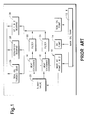
- Lube oil is circulated by a redundant set of AC pumps 10 which pump the lubricating oil from a main oil tank 12.
- a DC pump 14 is provided in case AC power to the site is interrupted.
- Relatively hot lubricating oil is pumped from the main oil tank 12 to one of a pair redundant oil-to-water heat exchanges 16 and 18 where the lubricating oil is cooled.
- the phase relatively hot is intended to be broadly construed and cover a large range of temperatures. In some respects the actual temperature of the oil in the tank 12 will be dependent upon the amount of heat imparted to the oil by turbine engine component(s) (e.g., gears and/or bearings 26-30). In general, the phrase relatively hot means that the temperature is greater than the temperature of the fuel by a difference enough to be usable to warm the fuel as discussed further below.
- One of the heat exchangers is in a stand-by condition and may be switched on-line by a three-way valve.
- the oil After passing through a fitter 22 or 24, the oil is delivered to a turning gear 26, a generator bearing 28, and turbine generator bearings 30. It should be appreciated that the gears and/or bearings 26-30 are example portion of turbine engine components. With the turbine and possible associated generator and mechanical drive being one example of a turbine engine component arrangement. After lubricating and absorbing heat from the rotating equipment, oil is returned to the main oil tank 12.
- the oil-to-water heat exchangers 16 and 18 are typically provided with a coolant including about 25% ethylene glycol and 75% water, which circulates through the heat exchanger where heat is extracted by the coolant.
- the plant auxiliary cooling water system ultimately rejects waste heat extracted by the coolant to the atmosphere.
- Various sensing devices are included in the lubricating system to ensure adequate oil level in the in the tank, oil pressure, and oil temperature.
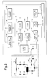
- FIG. 2 the existing gas turbine lube oil system illustrated in Figure 1 is shown as being modified by an arrangement according to one aspect of the present invention.
- Relatively hot lubricating oil is pumped from the main oil tank and is shunted by a line 32 and an isolation valve 34 to a double-wall or tube safety heat exchanger 36.
- Double-wall or tube heat exchangers are used where an intermixing of heat exchange media is to be avoided.
- the structure(s) for the exchange of heat may be varied.
- Heat is exchanged in the heat exchanger 36 with incoming, relatively cool, natural gas fuel for the turbine, which is shunted from an incoming fuel line 38 by an isolation valve 40. Heated fuel is delivered to the turbine while cooled lubricating oil is delivered to the lube oil system through a line 42 past a check valve 44.
- the heat exchanger 36 is one example of part of means for applying heat from the at least one heat generating source to relatively cold fuel for the turbine engine to preheat the fuel prior to ignition.
- the phase relatively cold is to be broadly construed and cover a large range of temperatures. In some respects the actual temperature of the fuel will be dependent upon ambient temperature of the fuel as stored and the temperature of the environment through which the incoming fuel line 38 extends.
- the phrase relatively cold means that the temperature is lower than a desired temperature at which the fuel can be combusted to obtain the greatest power output and/or fuel economy from the turbine.
- relatively cold is in relationship to the temperature of the oil so that the temperature of the fuel is greater than the relatively cold fuel by a difference enough to be usable to warm the fuel. It is to be appreciated that the example is contemplated not to limit the scope of the present invention.
- isolation valves 34 and 40 are opened, isolation valves 46, 48, 50, 52, 54, 56 and regulator valves 58 and 60 are closed. With the circuit in this condition, fuel gas in the line 38 is fed directly to the turbine while the heat exchanger 36 is isolated and lubricating oil circulates directly from the pump 10 through one of the heat exchangers 16 and 18 to the sites to be lubricated. All of the described valves may be activated either electrically or pneumatically.
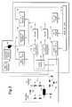
- FIG. 3 the existing gas turbine lube oil system illustrated in Figure 1 is shown as being modified by an arrangement according to a further aspect of this invention.
- This arrangement takes waste heat from the lube oil auxiliary cooling water and uses it to preheat the relatively cool natural gas fuel.
- auxiliary cooling water is pumped by a pump 62 to the heat exchangers 16 and 18 where it exchanges heat with hot lubricating oil from the main oil tank 12.
- Hot water is conducted from the heat exchanger 16 or 18 by a line 64 and exchanges heat in a double wall or tube heat exchanger 66 with incoming cool natural gas fuel shunted by an isolation valve 68. Heated fuel is delivered to the turbine while cooled water is returned through a line 70 to the auxiliary cooling water tank.
- the heat exchanger 66 is another example of part of means for applying heat from the at least one heat generating source to relatively cold fuel for the turbine engine to preheat the fuel prior to ignition. It is to be appreciated that the example is contemplated not to limit the scope of the present invention.
- the isolation valve 68 and a closed regulator valve 72 are opened, and isolation valves 74, 76, 78, 80, 82, 84 are closed.
- fuel gas is fed through the valve 68 directly to the turbine, while the heat exchanger 36 is isolated by the closed isolation valves 74-84 and the regulator valve 86.
- the auxiliary cooling water is then fed through the heat exchangers 16 and 18 and returned to the auxiliary cooling water tank, through the opened valve 116.
- the gas turbine lube oil system illustrated in Figure 1 is shown as being modified by an arrangement according to a still further aspect of this invention.
- This arrangement takes waste heat from the lube oil auxiliary cooling water and uses it to preheat the relatively cool natural gas fuel.
- This arrangement also takes waste heat from the generator cooling water and uses it to further preheat the natural gas fuel.
- auxiliary cooling water is pumped by a pump 88 to the heat exchangers 16 and 18 where it exchanges heat with hot lubricating oil from the main oil tank 12.
- Hot water is conducted from the heat exchangers 16 or 18 by a line 90 and exchanges heat in a double wall or tube heat exchanger 92 with incoming cool natural gas fuel shunted by an isolation valve 94.
- the relatively cool natural gas flows through a line 96 to a double wall or tube heat exchanger 98, to the heat exchanger 92 and then to the turbine.
- the cooled water flows through a line 100, past one way check valves 102 and 104 and back to an auxiliary cooling water tank 106.
- auxiliary cooling water is pumped by the pump 88 to the generator where it is heated by the generator and pumped to the heat exchanger 98 and then to the heat exchanger 92 through a line 108.
- the relatively cool water is then returned to the auxiliary cooling water tank through a line 110 and through a one-way check valve 104.
- the heat exchangers 92 and 98 are yet another example of part of means for applying heat from the at least one heat generating source to relatively cold fuel for the turbine engine to preheat the fuel prior to ignition. It is to be appreciated that the example is contemplated not to limit the scope of the present invention.
- the isolation valve 94 and closed regulator valve 116 and 138 are opened and isolation valves 118, 120, 124, 126, 128, 130, and 132 and regulator 134 and 136 are closed.
- fuel gas is fed through the valve 94 directly to the turbine, while the heat exchangers 92 and 98 are isolated.
- Water flowing from the heat exchangers 16 and 18 is blocked by the closed valve 134 and flows through the open valve 116, through the line 100, past the check valve 104 and back to the auxiliary cooling water tank 106.
- Generator cooling water is blocked by the closed valve 136 and flows through opened valve 138 to the auxiliary cooling water tank 106.
- the present invention provides a waste heat utilization method for preheating fuel for a turbine engine that powers a generator or a mechanical drive component.
- the method includes extracting heat from at least one heat generating source in the turbine engine and/or the generator and applying the heat to relatively cold fuel for the turbine engine to preheat the fuel prior to ignition.
- the present invention provides a method of providing a waste heat utilization system for preheating fuel for a turbine engine that powers a generator.
- the turbine engine and/or the generator include at least one heat generating source.
- the method includes providing means for applying heat from the at least one heat generating source to relatively cold fuel for the turbine engine to preheat the fuel prior to ignition.
- the method includes providing means for applying heat from the at least one heat generating source to relatively cold fuel for the turbine engine to preheat the fuel prior to ignition.
Landscapes
- Engineering & Computer Science (AREA)
- Chemical & Material Sciences (AREA)
- Combustion & Propulsion (AREA)
- Mechanical Engineering (AREA)
- General Engineering & Computer Science (AREA)
- Engine Equipment That Uses Special Cycles (AREA)
Abstract
Description
- This invention relates to process and apparatus for preheating fuel for a turbine engine during a generator, and more particularly to extracting heat from lubricating oil for the bearing of the turbine and the generator and applying that heat to relatively cool incoming fuel for the turbine to preheat the fuel.
- In recent years, pipeline natural gas fuel prices have continued to increase dramatically forcing heavy duty combustion turbine power plants to explore cost effective methods for combating rising fuel cost. As the need for higher thermal efficiency in power plants increases, a growing number of combined-cycle power plants are incorporating gas fuel heating as a means for improving overall efficiency. A gas fuel heater can be used to preheat fuel prior to combustion in a gas turbine. Gas fuel heating can reduce the amount of fuel required for achieving a specific firing temperature and thereby improves heat rate.
- Gas fuel pre-heating is also required from a dew point consideration. A superheat requirement is determined to ensure that gas is free of liquids and particularly, hydrocarbon droplets, during gas fuel operation. The superheat is a temperature difference between the supply and respective dew point temperature of the gas fuel. Dew point heaters are used to add the desired amount of superheat. Simple cycle power plants typically employ gas fired, oil-fired or electric heaters for fuel heating and combined cycle power plants can use feed water extracted from the heat recovery steam generator (HRSG) at an optimum location.
- In existing turbine power plants, heat is generated in the seal oil, turbine turning gear, gas turbine bearings, generator bearings and in the generator cooling water. Currently, the waste heat from gas turbine lubrication, generator and auxiliary system is rejected to the atmosphere via the plant auxiliary cooling water. There is a need to capture some of this waste heat for heating turbine fuel. This waste heat extraction will increase efficiency, reduce heat losses, increase fuel utilization, and lower operating costs for the combustion turbine power plants.
- The following presents a simplified summary of the invention in order to provide a basic understanding of some example aspects of the invention. This summary is not an extensive overview of the invention. Moreover, this summary is not intended to identify critical elements of the invention nor delineate the scope of the invention. The sole purpose of the summary is to present some concepts of the invention in simplified form as a prelude to the more detailed description that is presented later.
- In accordance with one aspect the present invention provides a waste heat utilization system for preheating fuel for a turbine engine component. The component includes at least one heat generating source. The system includes means for applying heat from the at least one heat generating source to relatively cold fuel for the turbine engine to preheat the fuel prior to ignition.
- In accordance with another aspect the present invention provides a waste heat utilization method for preheating fuel for a turbine engine component including extracting heat from at least one heat generating source in the turbine engine component and applying the heat to relatively cold fuel for the turbine engine component to preheat the fuel prior to ignition.
- In accordance with yet another aspect the present invention provides a method of providing a waste heat utilization system for preheating fuel for a turbine engine that powers a generator. The turbine engine and/or the generator include at least one heat generating source. The method includes providing means for applying heat from the at least one heat generating source to relatively cold fuel for the turbine engine to preheat the fuel prior to ignition.
- The foregoing and other aspects of the present invention will become apparent to those skilled in the art to which the present invention relates upon reading the following description with reference to the accompanying drawings, in which:
-
Fig. 1 is a schematic of a prior art lube oil circulating system; -
Fig. 2 is a schematic illustrating modifications to the prior art system according to one aspect of this invention; -
Fig. 3 is a schematic illustrating further modification to the prior art system according to a further aspect of this invention; and -
Fig. 4 is a schematic illustrating still further modifications to the prior art system according to a still further aspect of this invention. - Example embodiments that incorporate one or more aspects of the present invention are described and illustrated in the drawings. These illustrated examples are not intended to be a limitation on the present invention. For example, one or more aspects of the present invention can be utilized in other embodiments and even other types of devices. Moreover, certain terminology is used herein for convenience only and is not to be taken as a limitation on the present invention. Still further, in the drawings, the same reference numerals are employed for designating the same elements.
- Referring now to the drawings, and, particularly to
Fig. 1 an existing gas turbine lube oil schematic is illustrated. Lube oil is circulated by a redundant set ofAC pumps 10 which pump the lubricating oil from amain oil tank 12. ADC pump 14 is provided in case AC power to the site is interrupted. - Relatively hot lubricating oil is pumped from the
main oil tank 12 to one of a pair redundant oil-to-water heat exchanges tank 12 will be dependent upon the amount of heat imparted to the oil by turbine engine component(s) (e.g., gears and/or bearings 26-30). In general, the phrase relatively hot means that the temperature is greater than the temperature of the fuel by a difference enough to be usable to warm the fuel as discussed further below. One of the heat exchangers is in a stand-by condition and may be switched on-line by a three-way valve. After passing through afitter turning gear 26, a generator bearing 28, andturbine generator bearings 30. It should be appreciated that the gears and/or bearings 26-30 are example portion of turbine engine components. With the turbine and possible associated generator and mechanical drive being one example of a turbine engine component arrangement. After lubricating and absorbing heat from the rotating equipment, oil is returned to themain oil tank 12. - The oil-to-
water heat exchangers - Referring now to
Figure 2 , the existing gas turbine lube oil system illustrated inFigure 1 is shown as being modified by an arrangement according to one aspect of the present invention. - Relatively hot lubricating oil is pumped from the main oil tank and is shunted by a
line 32 and anisolation valve 34 to a double-wall or tubesafety heat exchanger 36. Double-wall or tube heat exchangers are used where an intermixing of heat exchange media is to be avoided. Of course, the structure(s) for the exchange of heat may be varied. Heat is exchanged in theheat exchanger 36 with incoming, relatively cool, natural gas fuel for the turbine, which is shunted from anincoming fuel line 38 by anisolation valve 40. Heated fuel is delivered to the turbine while cooled lubricating oil is delivered to the lube oil system through aline 42 past acheck valve 44. The lube oil then passes through the threeway valve 20 to one of theheat exchangers heat exchanger 36 is one example of part of means for applying heat from the at least one heat generating source to relatively cold fuel for the turbine engine to preheat the fuel prior to ignition. The phase relatively cold is to be broadly construed and cover a large range of temperatures. In some respects the actual temperature of the fuel will be dependent upon ambient temperature of the fuel as stored and the temperature of the environment through which theincoming fuel line 38 extends. In general, the phrase relatively cold means that the temperature is lower than a desired temperature at which the fuel can be combusted to obtain the greatest power output and/or fuel economy from the turbine. Also, relatively cold is in relationship to the temperature of the oil so that the temperature of the fuel is greater than the relatively cold fuel by a difference enough to be usable to warm the fuel. It is to be appreciated that the example is contemplated not to limit the scope of the present invention. - In order to isolate the fuel gas and lubricating oil shunts from the existing system during routine maintenance or sensed failure of the
heat exchanger 36, theisolation valves isolation valves regulator valves line 38 is fed directly to the turbine while theheat exchanger 36 is isolated and lubricating oil circulates directly from thepump 10 through one of theheat exchangers - Referring now to
Figure 3 , the existing gas turbine lube oil system illustrated inFigure 1 is shown as being modified by an arrangement according to a further aspect of this invention. This arrangement takes waste heat from the lube oil auxiliary cooling water and uses it to preheat the relatively cool natural gas fuel. - Relatively cool auxiliary cooling water is pumped by a
pump 62 to theheat exchangers main oil tank 12. Hot water is conducted from theheat exchanger line 64 and exchanges heat in a double wall ortube heat exchanger 66 with incoming cool natural gas fuel shunted by anisolation valve 68. Heated fuel is delivered to the turbine while cooled water is returned through aline 70 to the auxiliary cooling water tank. Thus, theheat exchanger 66 is another example of part of means for applying heat from the at least one heat generating source to relatively cold fuel for the turbine engine to preheat the fuel prior to ignition. It is to be appreciated that the example is contemplated not to limit the scope of the present invention. - In order to isolate the fuel gas shunt from the cooling water circuit during routine maintenance or sensed failure of the
heat exchanger 66, theisolation valve 68 and aclosed regulator valve 72 are opened, andisolation valves valve 68 directly to the turbine, while theheat exchanger 36 is isolated by the closed isolation valves 74-84 and theregulator valve 86. The auxiliary cooling water is then fed through theheat exchangers valve 116. - Referring now to
Figure 4 , the gas turbine lube oil system illustrated inFigure 1 is shown as being modified by an arrangement according to a still further aspect of this invention. This arrangement takes waste heat from the lube oil auxiliary cooling water and uses it to preheat the relatively cool natural gas fuel. This arrangement also takes waste heat from the generator cooling water and uses it to further preheat the natural gas fuel. - Relatively cool auxiliary cooling water is pumped by a
pump 88 to theheat exchangers main oil tank 12. Hot water is conducted from theheat exchangers tube heat exchanger 92 with incoming cool natural gas fuel shunted by anisolation valve 94. The relatively cool natural gas flows through aline 96 to a double wall ortube heat exchanger 98, to theheat exchanger 92 and then to the turbine. The cooled water flows through aline 100, past oneway check valves cooling water tank 106. - Relatively cool auxiliary cooling water is pumped by the
pump 88 to the generator where it is heated by the generator and pumped to theheat exchanger 98 and then to theheat exchanger 92 through aline 108. The relatively cool water is then returned to the auxiliary cooling water tank through aline 110 and through a one-way check valve 104. Thus, theheat exchangers - In order to isolate the fuel gas shunt from the cooling water circuit during routine maintenance or sensed failure of one or both of the
heat exchangers isolation valve 94 andclosed regulator valve isolation valves regulator 134 and 136 are closed. With the circuit in this condition, fuel gas is fed through thevalve 94 directly to the turbine, while theheat exchangers heat exchangers closed valve 134 and flows through theopen valve 116, through theline 100, past thecheck valve 104 and back to the auxiliarycooling water tank 106. Generator cooling water is blocked by the closed valve 136 and flows through openedvalve 138 to the auxiliarycooling water tank 106. - From the above example structural embodiments, it will be appreciated that associated methods provide other aspects of the present invention. For example, in accordance with one other aspect the present invention provides a waste heat utilization method for preheating fuel for a turbine engine that powers a generator or a mechanical drive component. The method includes extracting heat from at least one heat generating source in the turbine engine and/or the generator and applying the heat to relatively cold fuel for the turbine engine to preheat the fuel prior to ignition. As a further example, in accordance with yet another aspect the present invention provides a method of providing a waste heat utilization system for preheating fuel for a turbine engine that powers a generator. The turbine engine and/or the generator include at least one heat generating source. The method includes providing means for applying heat from the at least one heat generating source to relatively cold fuel for the turbine engine to preheat the fuel prior to ignition. As a further example, in accordance with another application of present invention in the case of a combined-cycle gas turbine, where cold gas fuel is typically heated in a performance heater by hot feed water extracted from HRSG at an optimum point. Gas turbine fuel upon being heated by the waste heat utilization system can be introduced in to a performance heater for achieving additional energy savings prior to ignition in a combined-cycle combustion gas turbine.
- The invention has been described with reference to the example embodiments described above. Modifications and alterations will occur to others upon a reading and understanding of this specification. Examples embodiments incorporating one or more aspects of the invention are intended to include all such modifications and alterations insofar as they come within the scope of the appended claims.
- Aspects of the present invention are defined in the following numbered clauses:
- 1. A waste heat utilization system for preheating fuel for a turbine engine component, the component including at least one heat generating source, the system including means for applying heat from the at least one heat generating source to relatively cold fuel for the turbine engine to preheat the fuel prior to ignition.
- 2. A system as set forth in
clause 1, wherein the at least one heat generating source in includes hot lubricating oil from the turbine engine component. - 3. A system as set forth in
clause 1 orclause 2, wherein the turbine engine component having at least one lubrication site, with lubricating oil being applied to the least one lubrication site and becoming relatively hot thereat, the system including means for pumping the relatively hot lubricating oil from the at least one lubrication site. - 4. A system as set forth in any one of the preceding clauses, wherein the at least one heat generating source includes heated component cooling water.
- 5. A system as set forth in any one of the preceding clauses, wherein the at least one heat generating source includes heated auxiliary cooling water.
- 6. A system as set forth in clause 5, wherein the auxiliary cooling water is heated by exchanging heat with hot lubricating oil from the turbine engine component.
- 7. A system as set forth in any one of the preceding clauses, wherein the means for applying heat includes a heat exchanger.
- 8. A system as set forth in clause 7, wherein the heat exchanger is a double wall or tube heat exchanger.
- 9. A waste heat utilization method for preheating fuel for a turbine engine component including extracting heat from at least one heat generating source in the turbine engine component and applying the heat to relatively cold fuel for the turbine engine component to preheat the fuel prior to ignition.
- 10. A method as set forth in clause 9, wherein the at least one heat generating source includes hot lubricating oil from the turbine engine component.
- 11. A method as set forth in clause 9 or
clause 10, wherein the turbine engine component having at least one lubrication site, with lubricating oil being applied to the least one lubrication site and becoming relatively hot thereat, the method including pumping the relatively hot lubricating oil from the at least one lubrication site. - 12. A method as set forth in any one of clauses 9 to 11, wherein the at least one heat generating source includes heated component cooling water.
- 13. A method as set forth in any one of clauses 9 to 12, wherein the at least one heat generating source includes heated auxiliary cooling water.
- 14. A method as set forth in clause 13, wherein the auxiliary cooling water is heated by exchanging heat with hot lubricating oil from the turbine engine component.
- 15. A method as set forth in any one of clauses 9 to 14, wherein extracted heat is applied to the relatively cold fuel by means of a heat exchanger.
- 16. A method as set forth in clause 15, wherein the heat exchanger is a double wall or tube heat exchanger.
- 17. A method of providing a waste heat utilization system for preheating fuel for a turbine engine that powers a generator, the turbine engine and/or the generator including at least one heat generating source, the method including providing means for applying heat from the at least one heat generating source to relatively cold fuel for the turbine engine to preheat the fuel prior to ignition.
- 18. A method as set forth in clause 17, wherein the at least one heat generating source includes hot lubricating oil from the turbine engine.
- 19. A method as set forth in clause 17 or
clause 18, wherein the at least one heat generating source includes heated generator cooling water. - 20. A method as set forth in any one of clauses 17 to 19, wherein the heat generating source is heated auxiliary cooling water, with the auxiliary cooling water being heated by exchanging heat with hot lubricating oil from the turbine engine.
Claims (15)
- A waste heat utilization system for preheating fuel for a turbine engine component, the component including at least one heat generating source (e.g., 26-30), the system including means (e.g.s, 36, 66, 92, 98) for applying heat from the at least one heat generating source to relatively cold fuel for the turbine engine to preheat the fuel prior to ignition.
- A system as set forth in claim 1, wherein the at least one heat generating source (e.g., 26-30) in includes hot lubricating oil from the turbine engine component.
- A system as set forth in claim 1 or claim 2, wherein the turbine engine component having at least one lubrication site (e.g., 26-30), with lubricating oil being applied to the least one lubrication site and becoming relatively hot thereat, the system including means for pumping (10) the relatively hot lubricating oil from the at least one lubrication site.
- A system as set forth in any one of the preceding claims, wherein the at least one heat generating source includes heated component cooling water (62).
- A system as set forth in any one of the preceding claims, wherein the at least one heat generating source includes heated auxiliary cooling water (106, 88).
- A system as set forth in claim 5, wherein the auxiliary cooling water is heated by exchanging heat (16, 18) with hot lubricating oil from the turbine engine component.
- A system as set forth in any one of the preceding claims, wherein the means for applying heat (e.g.s, 36, 66, 92, 98) includes a heat exchanger.
- A system as set forth in claim 7, wherein the heat exchanger (e.g.s, 36, 66, 92, 98) is a double wall or tube heat exchanger.
- A waste heat utilization method for preheating fuel for a turbine engine component including extracting heat from at least one heat generating source (e.g., 26-30) in the turbine engine component and applying the heat (e.g.s, 36, 66, 92, 98) to relatively cold fuel for the turbine engine component to preheat the fuel prior to ignition.
- A method as set forth in claim 9, wherein the at least one heat generating source (e.g., 26-30) includes hot lubricating oil from the turbine engine component.
- A method as set forth in claim 9 or claim 10, wherein the turbine engine component having at least one lubrication site (e.g., 26-30), with lubricating oil being applied to the least one lubrication site and becoming relatively hot thereat, the method including pumping (10) the relatively hot lubricating oil from the at least one lubrication site.
- A method as set forth in any one of claims 9 to 11, wherein the at least one heat generating source includes heated component cooling water (62).
- A method as set forth in any one of claims 9 to 12, wherein the at least one heat generating source includes heated auxiliary cooling water (106, 88).
- A method as set forth in claim 13, wherein the auxiliary cooling water is heated by exchanging heat (16, 18) with hot lubricating oil from the turbine engine component.
- A method as set forth in any one of claims 9 to 14, wherein extracted heat is applied to the relatively cold fuel by means of a heat exchanger (e.g.s, 36, 66, 92, 98).
Applications Claiming Priority (1)
| Application Number | Priority Date | Filing Date | Title |
|---|---|---|---|
| US12/372,127 US8438850B2 (en) | 2009-02-17 | 2009-02-17 | Waste heat utilization for pre-heating fuel |
Publications (2)
| Publication Number | Publication Date |
|---|---|
| EP2218890A1 true EP2218890A1 (en) | 2010-08-18 |
| EP2218890B1 EP2218890B1 (en) | 2014-10-08 |
Family
ID=42028221
Family Applications (1)
| Application Number | Title | Priority Date | Filing Date |
|---|---|---|---|
| EP10153343.8A Not-in-force EP2218890B1 (en) | 2009-02-17 | 2010-02-11 | Waste heat utilization for pre-heating fuel |
Country Status (4)
| Country | Link |
|---|---|
| US (1) | US8438850B2 (en) |
| EP (1) | EP2218890B1 (en) |
| JP (1) | JP2010190218A (en) |
| CN (1) | CN101806250B (en) |
Families Citing this family (14)
| Publication number | Priority date | Publication date | Assignee | Title |
|---|---|---|---|---|
| FR2970504B1 (en) * | 2011-01-19 | 2013-02-08 | Turbomeca | METHOD AND DEVICE FOR SUPPLYING LUBRICANTS |
| US8459033B2 (en) | 2011-07-05 | 2013-06-11 | General Electric Company | Systems and methods for modified wobbe index control with constant fuel temperature |
| JP5787651B2 (en) * | 2011-07-13 | 2015-09-30 | 三菱日立パワーシステムズ株式会社 | Gas turbine equipment and fuel temperature management method thereof |
| US9334802B2 (en) | 2011-10-31 | 2016-05-10 | United Technologies Corporation | Gas turbine engine thermal management system |
| US8495857B2 (en) * | 2011-10-31 | 2013-07-30 | United Technologies Corporation | Gas turbine engine thermal management system |
| US8443582B1 (en) | 2012-01-31 | 2013-05-21 | United Technologies Corporation | Gas turbine engine with geared turbofan and oil thermal management system |
| DE102012210702A1 (en) * | 2012-06-25 | 2014-01-02 | Siemens Aktiengesellschaft | Method for preheating fuel to be combusted in gas turbine, involves heating fuel by heat exchange with lubricant of gas turbine before injecting fuel into combustion chamber, where fuel flows through heat exchanger on secondary side |
| US20140130478A1 (en) * | 2012-11-09 | 2014-05-15 | General Electric Company | Gas turbomachine including a fuel pre-heat system |
| EP2954185B1 (en) | 2013-02-06 | 2022-05-04 | Raytheon Technologies Corporation | Multi-circuit lubrication system for a turbine engine |
| US9963994B2 (en) * | 2014-04-08 | 2018-05-08 | General Electric Company | Method and apparatus for clearance control utilizing fuel heating |
| CN104595032B (en) * | 2014-11-19 | 2016-08-24 | 上海交通大学 | A kind of multi-fan super large bypass ratio turbine push system |
| US10578020B2 (en) * | 2015-07-21 | 2020-03-03 | Unison Industries, Llc | Integral oil tank heat exchanger |
| US20170089265A1 (en) * | 2015-09-25 | 2017-03-30 | General Electric Company | Liquefied petroleum gas fuel conditioning system for gas turbine engines |
| CN114837808B (en) * | 2022-04-19 | 2023-08-08 | 苏州西热节能环保技术有限公司 | Waste heat flue gas utilization system of gas turbine generator set |
Citations (3)
| Publication number | Priority date | Publication date | Assignee | Title |
|---|---|---|---|---|
| GB1123921A (en) * | 1965-06-18 | 1968-08-14 | Francis Tin Chak Ma | Improvements in and relating to gas turbine engines |
| GB2131094A (en) | 1982-11-29 | 1984-06-13 | Gen Electric | Engine oil heat recovery system |
| EP1754863A2 (en) | 2005-08-19 | 2007-02-21 | General Electric Company | Lubricating oil heat recovery system for turbine engines |
Family Cites Families (17)
| Publication number | Priority date | Publication date | Assignee | Title |
|---|---|---|---|---|
| US2925712A (en) * | 1952-12-12 | 1960-02-23 | Rolls Royce | Aircraft fuel system with fuel heating means |
| US3147823A (en) * | 1962-11-23 | 1964-09-08 | Garrett Corp | Fuel evaporative engine oil cooling system |
| US4104873A (en) * | 1976-11-29 | 1978-08-08 | The United States Of America As Represented By The Administrator Of The United States National Aeronautics And Space Administration | Fuel delivery system including heat exchanger means |
| US4498524A (en) | 1977-08-08 | 1985-02-12 | Jacobsen Orval E | Heat exchanger with by-pass |
| US4773212A (en) * | 1981-04-01 | 1988-09-27 | United Technologies Corporation | Balancing the heat flow between components associated with a gas turbine engine |
| US4471211A (en) | 1983-10-05 | 1984-09-11 | Mitchell Reiss | Liquid to gas fuel heating device |
| US4696156A (en) * | 1986-06-03 | 1987-09-29 | United Technologies Corporation | Fuel and oil heat management system for a gas turbine engine |
| US4991644A (en) | 1989-07-12 | 1991-02-12 | Tufts University | Engine preheating process and system |
| US5363641A (en) * | 1993-08-06 | 1994-11-15 | United Technologies Corporation | Integrated auxiliary power system |
| FR2728938A1 (en) * | 1995-01-04 | 1996-07-05 | Snecma | OIL AND FUEL TEMPERATURE REGULATION SYSTEM IN A TURBOJET |
| JP3150567B2 (en) | 1995-04-14 | 2001-03-26 | 三菱重工業株式会社 | Gas turbine fuel heating device |
| DE60033738T2 (en) * | 1999-07-01 | 2007-11-08 | General Electric Co. | Device for humidifying and heating fuel gas |
| DE10041413B4 (en) * | 1999-08-25 | 2011-05-05 | Alstom (Switzerland) Ltd. | Method for operating a power plant |
| JP3767785B2 (en) | 1999-10-22 | 2006-04-19 | 本田技研工業株式会社 | Engine exhaust heat recovery device |
| EP1500804B1 (en) * | 2003-07-24 | 2014-04-30 | Hitachi, Ltd. | Gas turbine power plant |
| GB0318400D0 (en) * | 2003-08-06 | 2003-09-10 | Rolls Royce Plc | A fluid system |
| US7984606B2 (en) * | 2008-11-03 | 2011-07-26 | Propulsion, Gas Turbine, And Energy Evaluations, Llc | Systems and methods for thermal management in a gas turbine powerplant |
-
2009
- 2009-02-17 US US12/372,127 patent/US8438850B2/en not_active Expired - Fee Related
-
2010
- 2010-02-11 EP EP10153343.8A patent/EP2218890B1/en not_active Not-in-force
- 2010-02-15 JP JP2010029621A patent/JP2010190218A/en active Pending
- 2010-02-22 CN CN201010127122.9A patent/CN101806250B/en not_active Expired - Fee Related
Patent Citations (3)
| Publication number | Priority date | Publication date | Assignee | Title |
|---|---|---|---|---|
| GB1123921A (en) * | 1965-06-18 | 1968-08-14 | Francis Tin Chak Ma | Improvements in and relating to gas turbine engines |
| GB2131094A (en) | 1982-11-29 | 1984-06-13 | Gen Electric | Engine oil heat recovery system |
| EP1754863A2 (en) | 2005-08-19 | 2007-02-21 | General Electric Company | Lubricating oil heat recovery system for turbine engines |
Also Published As
| Publication number | Publication date |
|---|---|
| EP2218890B1 (en) | 2014-10-08 |
| US8438850B2 (en) | 2013-05-14 |
| JP2010190218A (en) | 2010-09-02 |
| US20100205977A1 (en) | 2010-08-19 |
| CN101806250A (en) | 2010-08-18 |
| CN101806250B (en) | 2015-01-14 |
Similar Documents
| Publication | Publication Date | Title |
|---|---|---|
| EP2218890B1 (en) | Waste heat utilization for pre-heating fuel | |
| EP2185872B1 (en) | Method and apparatus for starting a refrigerant system without preheating the oil | |
| AU2010326107B2 (en) | Utilizing steam and/or hot water generated using solar energy | |
| Nematollahi et al. | An evaluation of wind turbine waste heat recovery using organic Rankine cycle | |
| KR101660923B1 (en) | Steam turbine plant | |
| CN114893265B (en) | Heavy-duty gas-steam combined cycle power generation system with heat storage and energy storage module | |
| DE202007002602U1 (en) | ORC system for internal combustion engines | |
| CN101915475A (en) | Liquid heat energy circulating system and application thereof | |
| CN106321322A (en) | Integrated auxiliary machine power station cold region preheating system of engineering vehicle | |
| KR20120127015A (en) | Waste heat recycling system for ship | |
| CN106523053A (en) | Solar heat and thermal power plant coupling power generation and heat storage energy combination system and realization method | |
| JP2015017770A (en) | Boiler system | |
| US10006310B2 (en) | Steam power plant with an additional flexible solar system for the flexible integration of solar energy | |
| EP3473821B1 (en) | Combined heat and power plant and method for controlling a combined heat and power plant | |
| RU2440504C1 (en) | Cogeneration plant with internal combustion engine and stirling engine | |
| CN202157878U (en) | Liquid nitrogen evaporation system utilizing hydraulic brake | |
| CN201731673U (en) | Liquid heat energy circulating system | |
| CN206600944U (en) | Oilfield sewage source internal combustion engine drives compression type heat pump assembly | |
| RU2266414C2 (en) | Method of recovery of heat of exhaust gases of gas-turbine engine and heat power-generating plant for implementing the method | |
| WO2014063810A2 (en) | Device for converting thermal energy into mechanical energy and motor vehicle comprising a device of this type | |
| RU2629515C1 (en) | System for utilisation heat of closed type (versions) | |
| CA2835604C (en) | Steam power plant with an additional flexible solar system for the flexible integration of solar energy | |
| US12000312B2 (en) | Device for expanding a fluid | |
| RU2170885C1 (en) | Heat and power supply system | |
| RU89621U1 (en) | MANEUVERED GAS TURBINE HEAT ELECTROCENTRAL |
Legal Events
| Date | Code | Title | Description |
|---|---|---|---|
| PUAI | Public reference made under article 153(3) epc to a published international application that has entered the european phase |
Free format text: ORIGINAL CODE: 0009012 |
|
| AK | Designated contracting states |
Kind code of ref document: A1 Designated state(s): AT BE BG CH CY CZ DE DK EE ES FI FR GB GR HR HU IE IS IT LI LT LU LV MC MK MT NL NO PL PT RO SE SI SK SM TR |
|
| AX | Request for extension of the european patent |
Extension state: AL BA RS |
|
| 17P | Request for examination filed |
Effective date: 20110218 |
|
| 17Q | First examination report despatched |
Effective date: 20110408 |
|
| GRAP | Despatch of communication of intention to grant a patent |
Free format text: ORIGINAL CODE: EPIDOSNIGR1 |
|
| INTG | Intention to grant announced |
Effective date: 20140604 |
|
| GRAS | Grant fee paid |
Free format text: ORIGINAL CODE: EPIDOSNIGR3 |
|
| GRAA | (expected) grant |
Free format text: ORIGINAL CODE: 0009210 |
|
| AK | Designated contracting states |
Kind code of ref document: B1 Designated state(s): AT BE BG CH CY CZ DE DK EE ES FI FR GB GR HR HU IE IS IT LI LT LU LV MC MK MT NL NO PL PT RO SE SI SK SM TR |
|
| REG | Reference to a national code |
Ref country code: GB Ref legal event code: FG4D |
|
| REG | Reference to a national code |
Ref country code: AT Ref legal event code: REF Ref document number: 690767 Country of ref document: AT Kind code of ref document: T Effective date: 20141015 Ref country code: CH Ref legal event code: EP |
|
| REG | Reference to a national code |
Ref country code: IE Ref legal event code: FG4D |
|
| REG | Reference to a national code |
Ref country code: DE Ref legal event code: R096 Ref document number: 602010019333 Country of ref document: DE Effective date: 20141120 |
|
| REG | Reference to a national code |
Ref country code: NL Ref legal event code: VDEP Effective date: 20141008 |
|
| REG | Reference to a national code |
Ref country code: AT Ref legal event code: MK05 Ref document number: 690767 Country of ref document: AT Kind code of ref document: T Effective date: 20141008 |
|
| REG | Reference to a national code |
Ref country code: LT Ref legal event code: MG4D |
|
| PG25 | Lapsed in a contracting state [announced via postgrant information from national office to epo] |
Ref country code: NL Free format text: LAPSE BECAUSE OF FAILURE TO SUBMIT A TRANSLATION OF THE DESCRIPTION OR TO PAY THE FEE WITHIN THE PRESCRIBED TIME-LIMIT Effective date: 20141008 |
|
| PG25 | Lapsed in a contracting state [announced via postgrant information from national office to epo] |
Ref country code: LT Free format text: LAPSE BECAUSE OF FAILURE TO SUBMIT A TRANSLATION OF THE DESCRIPTION OR TO PAY THE FEE WITHIN THE PRESCRIBED TIME-LIMIT Effective date: 20141008 Ref country code: PT Free format text: LAPSE BECAUSE OF FAILURE TO SUBMIT A TRANSLATION OF THE DESCRIPTION OR TO PAY THE FEE WITHIN THE PRESCRIBED TIME-LIMIT Effective date: 20150209 Ref country code: IS Free format text: LAPSE BECAUSE OF FAILURE TO SUBMIT A TRANSLATION OF THE DESCRIPTION OR TO PAY THE FEE WITHIN THE PRESCRIBED TIME-LIMIT Effective date: 20150208 Ref country code: NO Free format text: LAPSE BECAUSE OF FAILURE TO SUBMIT A TRANSLATION OF THE DESCRIPTION OR TO PAY THE FEE WITHIN THE PRESCRIBED TIME-LIMIT Effective date: 20150108 Ref country code: FI Free format text: LAPSE BECAUSE OF FAILURE TO SUBMIT A TRANSLATION OF THE DESCRIPTION OR TO PAY THE FEE WITHIN THE PRESCRIBED TIME-LIMIT Effective date: 20141008 Ref country code: ES Free format text: LAPSE BECAUSE OF FAILURE TO SUBMIT A TRANSLATION OF THE DESCRIPTION OR TO PAY THE FEE WITHIN THE PRESCRIBED TIME-LIMIT Effective date: 20141008 |
|
| PG25 | Lapsed in a contracting state [announced via postgrant information from national office to epo] |
Ref country code: PL Free format text: LAPSE BECAUSE OF FAILURE TO SUBMIT A TRANSLATION OF THE DESCRIPTION OR TO PAY THE FEE WITHIN THE PRESCRIBED TIME-LIMIT Effective date: 20141008 Ref country code: LV Free format text: LAPSE BECAUSE OF FAILURE TO SUBMIT A TRANSLATION OF THE DESCRIPTION OR TO PAY THE FEE WITHIN THE PRESCRIBED TIME-LIMIT Effective date: 20141008 Ref country code: HR Free format text: LAPSE BECAUSE OF FAILURE TO SUBMIT A TRANSLATION OF THE DESCRIPTION OR TO PAY THE FEE WITHIN THE PRESCRIBED TIME-LIMIT Effective date: 20141008 Ref country code: GR Free format text: LAPSE BECAUSE OF FAILURE TO SUBMIT A TRANSLATION OF THE DESCRIPTION OR TO PAY THE FEE WITHIN THE PRESCRIBED TIME-LIMIT Effective date: 20150109 Ref country code: SE Free format text: LAPSE BECAUSE OF FAILURE TO SUBMIT A TRANSLATION OF THE DESCRIPTION OR TO PAY THE FEE WITHIN THE PRESCRIBED TIME-LIMIT Effective date: 20141008 Ref country code: AT Free format text: LAPSE BECAUSE OF FAILURE TO SUBMIT A TRANSLATION OF THE DESCRIPTION OR TO PAY THE FEE WITHIN THE PRESCRIBED TIME-LIMIT Effective date: 20141008 Ref country code: CY Free format text: LAPSE BECAUSE OF FAILURE TO SUBMIT A TRANSLATION OF THE DESCRIPTION OR TO PAY THE FEE WITHIN THE PRESCRIBED TIME-LIMIT Effective date: 20141008 |
|
| PG25 | Lapsed in a contracting state [announced via postgrant information from national office to epo] |
Ref country code: BE Free format text: LAPSE BECAUSE OF NON-PAYMENT OF DUE FEES Effective date: 20150228 |
|
| REG | Reference to a national code |
Ref country code: DE Ref legal event code: R097 Ref document number: 602010019333 Country of ref document: DE |
|
| PG25 | Lapsed in a contracting state [announced via postgrant information from national office to epo] |
Ref country code: DK Free format text: LAPSE BECAUSE OF FAILURE TO SUBMIT A TRANSLATION OF THE DESCRIPTION OR TO PAY THE FEE WITHIN THE PRESCRIBED TIME-LIMIT Effective date: 20141008 Ref country code: EE Free format text: LAPSE BECAUSE OF FAILURE TO SUBMIT A TRANSLATION OF THE DESCRIPTION OR TO PAY THE FEE WITHIN THE PRESCRIBED TIME-LIMIT Effective date: 20141008 Ref country code: RO Free format text: LAPSE BECAUSE OF FAILURE TO SUBMIT A TRANSLATION OF THE DESCRIPTION OR TO PAY THE FEE WITHIN THE PRESCRIBED TIME-LIMIT Effective date: 20141008 Ref country code: CZ Free format text: LAPSE BECAUSE OF FAILURE TO SUBMIT A TRANSLATION OF THE DESCRIPTION OR TO PAY THE FEE WITHIN THE PRESCRIBED TIME-LIMIT Effective date: 20141008 Ref country code: SK Free format text: LAPSE BECAUSE OF FAILURE TO SUBMIT A TRANSLATION OF THE DESCRIPTION OR TO PAY THE FEE WITHIN THE PRESCRIBED TIME-LIMIT Effective date: 20141008 |
|
| PLBE | No opposition filed within time limit |
Free format text: ORIGINAL CODE: 0009261 |
|
| STAA | Information on the status of an ep patent application or granted ep patent |
Free format text: STATUS: NO OPPOSITION FILED WITHIN TIME LIMIT |
|
| PG25 | Lapsed in a contracting state [announced via postgrant information from national office to epo] |
Ref country code: IT Free format text: LAPSE BECAUSE OF FAILURE TO SUBMIT A TRANSLATION OF THE DESCRIPTION OR TO PAY THE FEE WITHIN THE PRESCRIBED TIME-LIMIT Effective date: 20141008 |
|
| 26N | No opposition filed |
Effective date: 20150709 |
|
| PG25 | Lapsed in a contracting state [announced via postgrant information from national office to epo] |
Ref country code: LU Free format text: LAPSE BECAUSE OF FAILURE TO SUBMIT A TRANSLATION OF THE DESCRIPTION OR TO PAY THE FEE WITHIN THE PRESCRIBED TIME-LIMIT Effective date: 20150211 |
|
| REG | Reference to a national code |
Ref country code: CH Ref legal event code: PL |
|
| PG25 | Lapsed in a contracting state [announced via postgrant information from national office to epo] |
Ref country code: LI Free format text: LAPSE BECAUSE OF NON-PAYMENT OF DUE FEES Effective date: 20150228 Ref country code: MC Free format text: LAPSE BECAUSE OF FAILURE TO SUBMIT A TRANSLATION OF THE DESCRIPTION OR TO PAY THE FEE WITHIN THE PRESCRIBED TIME-LIMIT Effective date: 20141008 Ref country code: CH Free format text: LAPSE BECAUSE OF NON-PAYMENT OF DUE FEES Effective date: 20150228 |
|
| REG | Reference to a national code |
Ref country code: IE Ref legal event code: MM4A |
|
| REG | Reference to a national code |
Ref country code: FR Ref legal event code: ST Effective date: 20151030 |
|
| PG25 | Lapsed in a contracting state [announced via postgrant information from national office to epo] |
Ref country code: IE Free format text: LAPSE BECAUSE OF NON-PAYMENT OF DUE FEES Effective date: 20150211 |
|
| PG25 | Lapsed in a contracting state [announced via postgrant information from national office to epo] |
Ref country code: SI Free format text: LAPSE BECAUSE OF FAILURE TO SUBMIT A TRANSLATION OF THE DESCRIPTION OR TO PAY THE FEE WITHIN THE PRESCRIBED TIME-LIMIT Effective date: 20141008 Ref country code: FR Free format text: LAPSE BECAUSE OF NON-PAYMENT OF DUE FEES Effective date: 20150302 |
|
| PG25 | Lapsed in a contracting state [announced via postgrant information from national office to epo] |
Ref country code: MT Free format text: LAPSE BECAUSE OF FAILURE TO SUBMIT A TRANSLATION OF THE DESCRIPTION OR TO PAY THE FEE WITHIN THE PRESCRIBED TIME-LIMIT Effective date: 20141008 |
|
| PG25 | Lapsed in a contracting state [announced via postgrant information from national office to epo] |
Ref country code: HU Free format text: LAPSE BECAUSE OF FAILURE TO SUBMIT A TRANSLATION OF THE DESCRIPTION OR TO PAY THE FEE WITHIN THE PRESCRIBED TIME-LIMIT; INVALID AB INITIO Effective date: 20100211 Ref country code: BG Free format text: LAPSE BECAUSE OF FAILURE TO SUBMIT A TRANSLATION OF THE DESCRIPTION OR TO PAY THE FEE WITHIN THE PRESCRIBED TIME-LIMIT Effective date: 20141008 Ref country code: SM Free format text: LAPSE BECAUSE OF FAILURE TO SUBMIT A TRANSLATION OF THE DESCRIPTION OR TO PAY THE FEE WITHIN THE PRESCRIBED TIME-LIMIT Effective date: 20141008 |
|
| PG25 | Lapsed in a contracting state [announced via postgrant information from national office to epo] |
Ref country code: TR Free format text: LAPSE BECAUSE OF FAILURE TO SUBMIT A TRANSLATION OF THE DESCRIPTION OR TO PAY THE FEE WITHIN THE PRESCRIBED TIME-LIMIT Effective date: 20141008 |
|
| PGFP | Annual fee paid to national office [announced via postgrant information from national office to epo] |
Ref country code: GB Payment date: 20180227 Year of fee payment: 9 |
|
| PG25 | Lapsed in a contracting state [announced via postgrant information from national office to epo] |
Ref country code: MK Free format text: LAPSE BECAUSE OF FAILURE TO SUBMIT A TRANSLATION OF THE DESCRIPTION OR TO PAY THE FEE WITHIN THE PRESCRIBED TIME-LIMIT Effective date: 20141008 |
|
| PGFP | Annual fee paid to national office [announced via postgrant information from national office to epo] |
Ref country code: DE Payment date: 20180227 Year of fee payment: 9 |
|
| REG | Reference to a national code |
Ref country code: DE Ref legal event code: R119 Ref document number: 602010019333 Country of ref document: DE |
|
| GBPC | Gb: european patent ceased through non-payment of renewal fee |
Effective date: 20190211 |
|
| PG25 | Lapsed in a contracting state [announced via postgrant information from national office to epo] |
Ref country code: DE Free format text: LAPSE BECAUSE OF NON-PAYMENT OF DUE FEES Effective date: 20190903 Ref country code: GB Free format text: LAPSE BECAUSE OF NON-PAYMENT OF DUE FEES Effective date: 20190211 |