EP2218641B1 - Rückströmungnetzwerkelement für Flugzeuge - Google Patents
Rückströmungnetzwerkelement für Flugzeuge Download PDFInfo
- Publication number
- EP2218641B1 EP2218641B1 EP10153238.0A EP10153238A EP2218641B1 EP 2218641 B1 EP2218641 B1 EP 2218641B1 EP 10153238 A EP10153238 A EP 10153238A EP 2218641 B1 EP2218641 B1 EP 2218641B1
- Authority
- EP
- European Patent Office
- Prior art keywords
- network element
- strips
- aircraft
- floor
- current return
- Prior art date
- Legal status (The legal status is an assumption and is not a legal conclusion. Google has not performed a legal analysis and makes no representation as to the accuracy of the status listed.)
- Not-in-force
Links
- 230000000452 restraining effect Effects 0.000 claims 1
- 229910052751 metal Inorganic materials 0.000 description 10
- 239000002184 metal Substances 0.000 description 9
- 238000001465 metallisation Methods 0.000 description 6
- 238000005304 joining Methods 0.000 description 5
- 238000012423 maintenance Methods 0.000 description 5
- 238000004519 manufacturing process Methods 0.000 description 5
- 239000002131 composite material Substances 0.000 description 4
- 239000013521 mastic Substances 0.000 description 4
- 239000000463 material Substances 0.000 description 4
- 230000015572 biosynthetic process Effects 0.000 description 3
- 230000002829 reductive effect Effects 0.000 description 3
- 230000000284 resting effect Effects 0.000 description 3
- 230000015556 catabolic process Effects 0.000 description 2
- 230000007797 corrosion Effects 0.000 description 2
- 238000005260 corrosion Methods 0.000 description 2
- 238000006731 degradation reaction Methods 0.000 description 2
- 239000000835 fiber Substances 0.000 description 2
- 230000000670 limiting effect Effects 0.000 description 2
- 239000007769 metal material Substances 0.000 description 2
- 239000000203 mixture Substances 0.000 description 2
- 239000003973 paint Substances 0.000 description 2
- 230000002028 premature Effects 0.000 description 2
- 239000011347 resin Substances 0.000 description 2
- 229920005989 resin Polymers 0.000 description 2
- 206010042255 Struck by lightning Diseases 0.000 description 1
- 239000000956 alloy Substances 0.000 description 1
- 229910045601 alloy Inorganic materials 0.000 description 1
- 230000004075 alteration Effects 0.000 description 1
- 229910052782 aluminium Inorganic materials 0.000 description 1
- XAGFODPZIPBFFR-UHFFFAOYSA-N aluminium Chemical compound [Al] XAGFODPZIPBFFR-UHFFFAOYSA-N 0.000 description 1
- 239000002519 antifouling agent Substances 0.000 description 1
- 239000010953 base metal Substances 0.000 description 1
- 238000003698 laser cutting Methods 0.000 description 1
- 238000012986 modification Methods 0.000 description 1
- 230000004048 modification Effects 0.000 description 1
- 238000012544 monitoring process Methods 0.000 description 1
- 238000010422 painting Methods 0.000 description 1
- 230000036961 partial effect Effects 0.000 description 1
- 230000000737 periodic effect Effects 0.000 description 1
- 230000002787 reinforcement Effects 0.000 description 1
- 238000005728 strengthening Methods 0.000 description 1
- 238000009966 trimming Methods 0.000 description 1
- 239000011800 void material Substances 0.000 description 1
Images


Classifications
-
- H—ELECTRICITY
- H01—ELECTRIC ELEMENTS
- H01R—ELECTRICALLY-CONDUCTIVE CONNECTIONS; STRUCTURAL ASSOCIATIONS OF A PLURALITY OF MUTUALLY-INSULATED ELECTRICAL CONNECTING ELEMENTS; COUPLING DEVICES; CURRENT COLLECTORS
- H01R25/00—Coupling parts adapted for simultaneous co-operation with two or more identical counterparts, e.g. for distributing energy to two or more circuits
- H01R25/14—Rails or bus-bars constructed so that the counterparts can be connected thereto at any point along their length
-
- B—PERFORMING OPERATIONS; TRANSPORTING
- B64—AIRCRAFT; AVIATION; COSMONAUTICS
- B64C—AEROPLANES; HELICOPTERS
- B64C1/00—Fuselages; Constructional features common to fuselages, wings, stabilising surfaces or the like
- B64C1/18—Floors
-
- H—ELECTRICITY
- H02—GENERATION; CONVERSION OR DISTRIBUTION OF ELECTRIC POWER
- H02G—INSTALLATION OF ELECTRIC CABLES OR LINES, OR OF COMBINED OPTICAL AND ELECTRIC CABLES OR LINES
- H02G3/00—Installations of electric cables or lines or protective tubing therefor in or on buildings, equivalent structures or vehicles
- H02G3/36—Installations of cables or lines in walls, floors or ceilings
- H02G3/38—Installations of cables or lines in walls, floors or ceilings the cables or lines being installed in preestablished conduits or ducts
- H02G3/383—Installations of cables or lines in walls, floors or ceilings the cables or lines being installed in preestablished conduits or ducts in floors
Definitions
- the present invention generally relates to the current return for aircraft electrical appliances on an aircraft, and more particularly relates to an aircraft current return network element.
- the electrical power supply of the electrical appliances on board an aircraft is usually carried out by an electric power supply cable and by a current return network produced by the structure of the aircraft.
- the elements of the fuselage and its primary structure are made of metal material, which allows the formation of an electrical network return functional and fault currents.
- the structural elements of the fuselage are increasingly made of composite material comprising a mixture of fibers and resin, in order to achieve a significant mass gain while preserving or improving the mechanical characteristics of said structural elements.
- Composite materials with low electrical conductivity, fuselage structure elements of composite material can no longer form a current return network.
- An aircraft floor usually incorporates longitudinal members and cross members assembled by means of metal joining means.
- a protective paint against corrosion usually covers metal parts, painting that is usually not conductive.
- an interposing mastic is often present at the level of the structural junctions between the metal parts in order to avoid the phenomena of wear of contact between said parts.
- the metallization operation generally performed manually, then consists of removing the interposing mastic and stripping the paint, to locally reveal the base metal of the metal part.
- the connecting means can then be mounted on said piece at the prepared contact surface.
- the electrical junction made by the connecting means is obtained by a manual metallization operation, which can cause, therefore, some harmful imperfections.
- joining means makes it necessary to perform a large number of metallization operations, preferably one for each of said joining means.
- This operation manual, significantly extends the production cycle of the aircraft.
- the monitoring and maintenance cycle of each junction is also particularly increased. This necessarily leads to high costs of implementation and maintenance.
- US 5,127,601 A , WO2005 / 071788 A , US 2005/213278 A1 and FR 2 914 622 A describe network elements for aircraft.
- the main purpose of the invention is to present a current feedback network element at least partially overcoming the disadvantages mentioned above relating to the embodiments of the prior art.
- the subject of the invention is an aircraft current return network element comprising a plurality of intersecting electrically conductive strips and made in one piece, spaced apart from one another so as to form therebetween plurality of openings.
- the current return network element according to the invention has electrical and structural junctions naturally formed by the intersections of said strips, because the network element they form is made in one piece.
- said strips intersect without being superimposed on each other at intersections. It is then not necessary to provide reported means to ensure the electrical connection between said strips. The risk of loss of connection between the bands is thus eliminated.
- the invention makes it possible to substantially reduce the production cycle time since the metallization operations previously described are no longer necessary.
- the duration and maintenance costs of the line return network are also particularly reduced compared to the prior art described above.
- the number of bands can be high so as to form a particularly fine mesh, in order to obtain a network element with high reliability. Unlike the prior art, the number of bands, and therefore the number of intercrossings, does not increase the potential risks of degradation of electrical properties, or the duration of production and maintenance cycles.
- the geometry of said network element is easily adaptable to that of any aircraft part that is to be equipped with such a network element.
- the arrangement of the intersecting bands, and that of the openings can be chosen according to the geometry of the aircraft elements along which it is desired to route said strips.
- Each band is preferably rigid.
- said openings are arranged substantially periodically.
- said intersecting strips are substantially perpendicular to each other so as to form substantially rectangular or square openings.
- the network element is monolithic.
- said strips are made of the same material, which makes the electrical conductivity substantially homogeneous within said strips. Any abnormally high temperature zones located at the interfaces between different materials are thus removed. The risks of premature fatigue of the network element are therefore reduced.
- the material may be selected from those having a high conductivity in order to limit the voltage drop along the network element.
- the network element according to the invention has a generally wavy shape.
- general wavy form means a general shape having or having regular and parallel corrugations.
- the mechanical strength is then reinforced by the presence of the corrugations.
- the thickness of said strips is between 1mm and 5mm.
- the thickness is preferably substantially constant along each strip, and substantially the same for all said strips.
- said strips are intersecting substantially perpendicularly.
- the invention also relates to an aircraft part comprising at least one current return network element according to any one of the characteristics mentioned above.
- said aircraft part comprises a floor comprising a plurality of cross members, a network element being in abutment against said crosspieces.
- said sleepers have a support function, or maintenance of said network element. Moreover, it can participate in the structural strengthening of said floor.
- Said network element may bear against the upper or lower surface of said sleepers.
- Said aircraft part may comprise floor rails, said network element being interposed between said rails and said sleepers. Said network element is then preferably supported against the upper surface of the crosspieces.
- Said rails can be seat rails mounted on a passenger floor, or freight rails mounted on a so-called cargo floor.
- Said aircraft part may also comprise at least one electrical power supply cable support, said cable support being mounted on said network element by holding means. Said network element is then preferably supported against the lower surface of the sleepers.
- said aircraft part may comprise a fuselage portion comprising a plurality of structural frames, said network element being in support against said frames. Said network element can then participate in the structural reinforcement of said fuselage portion.
- the current feedback network element 1 according to the first preferred embodiment of the invention is shown schematically on the figure 1 in top view.
- X is referred to as the longitudinal direction of the aircraft
- Y is the direction transversely oriented relative to the aircraft
- Z is the vertical direction.
- front and rear are to be considered in relation to a direction of advancement of the aircraft obtained as a result of the thrust exerted by the engines of the aircraft, this direction coinciding substantially with the X direction.
- the network element 1 comprises a plurality of interleaved electrically conductive strips 2 made in one piece, spaced apart from each other so as to form therebetween a plurality of openings 4.
- Said strip is a piece whose length is much greater than its width, for example twice as long.
- the thickness of said strip may be equal to or less than its width, preferably less.
- the thickness may be between 0.5 and 15 millimeters, preferably between 1 and 5 millimeters.
- Each band 2 has a substantially constant thickness and width.
- the thickness and width are substantially identical for all said strips 2.
- Said strips 2 are electrically conductive, for example aluminum or in one of its alloys. Preferably, they are made of a material whose electrical conductivity is sufficient to allow the return of the current, both being resistant to corrosion.
- Said strips 2 intersect so as to form a mesh where each interlacing 3 forms a node of the mesh. They are spaced apart from each other so as to form between them a plurality of openings 4.
- opening means a void space passing through said network element.
- Said openings 4 are arranged in a substantially periodic manner, and said strips 2 forming a crisscrossing 3 are substantially perpendicular to each other, so as to form openings 4 substantially rectangular or square.
- Said strips 2 are made in one piece, so as to jointly form a single piece. No insert is therefore necessary to ensure the structural junction between said strips. In addition, the strips intersect without being superimposed on one another at the crisscrossing.
- the figure 2 shows a cross section of a fuselage 5 having a passenger floor 6.
- a current return network element 1, as described above, can be mounted on the floor 6, more precisely on the primary structure of the floor 6.
- the primary structure comprises a plurality of longitudinal members 7 extending in the longitudinal direction X of the aircraft, and a plurality of cross members 8 extending in the transverse direction Y.
- each cross member 8 is made in one piece and extends in the Y direction over the entire width of the floor structure 6.
- the cross members 8 and the longitudinal members 7 may be made of metal or composite material comprising a mixture of fibers and resin.
- Said network element 1 can bear against the upper surface 8A or lower 8B of said crossbars 8.
- bearing against By bearing against is meant disposed in direct or indirect contact against said sleepers 8.
- the indirect contact can be achieved by means of an interposing mastic.
- the network element 1 can be fixed to the cross members 8 by riveting or bolting, or by lockable connectors.
- said network element 1 comprises, for each floor 8, a strip 2 disposed opposite said crossbar 8, as shown in FIG. figure 1 where each dotted line symbolizes a cross 8.
- said strip runs along said cross member 8 opposite which it is arranged.
- Said network element 1 may have a number of strips 2 opposite said sleepers 8 less than the number thereof.
- a strip 2 may be arranged facing a crosspiece 8 every two or three sleepers, or more. Said network element 1 then has a reduced mass, thereby participating in the general requirement of mass saving.
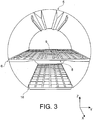
- figures 2 and 3 show metal rails 9 which can be mounted on the floor structure, for example rails 9 ensuring the attachment of passenger seats (not shown).
- the rails 9 usually extend along the longitudinal axis X of the fuselage and are connected to each other by cross members 8 which extend perpendicular thereto.
- Said network element 1 is then advantageously interposed between said rails 9 and said sleepers 8.
- said network element 1 comprises strips 2 oriented in the longitudinal direction of the rails 9.
- a strip 2 is disposed facing each rail 9.
- strips may follow said rails 9 and other strips of the same network element 1 may follow said sleepers 8.
- said rails 9 participate in the formation of the current return network by electrically connecting the electrical devices possibly disposed at the passenger seats to said network element 1 back current.
- the current return network may comprise a network element 1 resting on the upper surface 8A of the cross-members 8 and / or a network element 1 bearing against the lower surface 8B of the cross-members 8.
- Said supports 10 for electrical cables may comprise a profiled metal body 11 which participates in the return of the current flowing in the cables.
- Each cable support 10 can be mounted on said network element by means of holding means 12 ( Figure 4B ).
- Said holding means 12 may be metallic, so as to ensure electrical continuity with said cable supports.
- Said supports 10 can also provide harness support, and participate in protection against the indirect effects of lightning.
- These holding means 12 may be a pair of U-shaped rails 12 welded or fixed to the lower surface of said network element 1, as shown in FIG. Figure 4B .
- the two rails 12 are arranged so as to cooperate with the T-shaped profiled body 11 of said cable support 10.
- said holding means 12 extend all along said network element 1 in a continuous manner. They can alternatively extend discontinuously.
- These cable supports 10 can thus improve the structural rigidity of said network element 1.
- each network element 1, whether resting on the upper surface 8A or lower 8B of the crosspieces 8, extends in the transverse direction Y over the entire width of the floor 6.
- said network element 1 can be mounted on frames 13 of the fuselage structure of the aircraft, by fastening means 14 arranged at its side edges, as shown by FIGS. Figures 1 and 2 . It can be fixed by riveting or bolting, or by lockable connectors.
- said network element 1 advantageously has a modular structure, and thus allows the arrangement along the longitudinal direction X and / or the transverse direction Y of a plurality of successive network elements 1 so that extend substantially over the entire length and / or width of the floor 6.
- each network element 1 then comprises means 15 of electrical junction for ensuring electrical continuity between the neighboring network element 1.
- These means 15A, 15B of electrical junction may be contact areas disposed respectively on the front portion of a first network element 1 and on the rear portion of the second network element 1 consecutive.
- electrical connection means 15 may be provided at the lateral edges of each network element 1.
- each network element may comprise electrical junction elements for the purpose of arranging a plurality of network elements 1 at a time in the longitudinal X and transverse Y directions.
- FIG. 2 describes a current return network element mounted on a passenger floor 6, said network element can also be mounted on a so-called cargo floor 16 for goods.
- said network element can be in abutment against a plurality of fuselage frames 13, on a longitudinal portion of the fuselage 5.
- said element of network 1 ensures the return of current of electrical devices that can be placed in an upper or lower part of the fuselage 1.
- Said network element may also have a modular structure as described above.
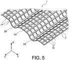
- the network element 1 may have a generally wavy shape.
- the network element comprises a first plurality of strips 2 extending in a first direction, which intersects with a second plurality of strips 2 extending in a second direction.
- the intercrossing and the one-piece production of said strips are identical to what has been described above.
- the first and second directions here are substantially orthogonal and coincide substantially with the longitudinal X and transverse Y directions, respectively. Alternatively, they can define between them a non-zero angle other than 90 °.
- Each strip 2 of said first plurality 17 extends substantially plane in the direction X, while each strip 2 of said second plurality 18 extends undulated substantially in the direction Y.
- the strips 2 of said second plurality 18 each have a succession of concave portions and convex portions.
- said first plurality of strips 2 comprises a band 2A defining the high peak of the wave considered. and a band 2B defining the low peak of said ripple.
- the network element 1 may comprise fixing openings disposed at the level of the intersections between each of the strips 2A and the strips 2 of the second plurality 18. Also, the network element 1 may be mounted, for example, on a floor aircraft through the strips 2A placed against the floor as described above. Mounting means, such as rivets, bolts or lockable connectors, are then arranged through the fastening openings.
- the strips 2B are then not in support against the floor, and can in particular be used to maintain harnesses.
- the general shape of the network element remains here substantially flat. Indeed, the set of bands 2A of the first plurality 17 is substantially contained in the same plane. Similarly, the set of bands 2B is substantially contained in the same plane, the latter being parallel to the plane of the bands 2A.
- the general shape of the network element 1 can be substantially curved, especially when it is mounted on a plurality of fuselage frames of a fuselage portion, as described above.
- the set of strips 2A of the first plurality 17 is substantially contained in the same curved surface.
- the set of strips 2B is substantially contained in the same area curve, the latter being parallel to the curved surface of the strips 2A.
- the network element according to the invention can be achieved by trimming a corrugated sheet or not, for example by laser cutting, or from expanded metal.
Landscapes
- Engineering & Computer Science (AREA)
- Mechanical Engineering (AREA)
- Aviation & Aerospace Engineering (AREA)
- Architecture (AREA)
- Civil Engineering (AREA)
- Structural Engineering (AREA)
- Installation Of Indoor Wiring (AREA)
- Elimination Of Static Electricity (AREA)
Claims (9)
- Stromrückführungsnetzelement (1) für ein Flugzeug, dadurch gekennzeichnet, dass es mehrere elektrisch leitfähige starre Bänder (2) umfasst, die verflochten und einteilig hergestellt sind und voneinander beabstandet sind, um zwischen ihnen mehrere Öffnungen (4) zu bilden, wobei das Stromrückführungsnetzelement (1) eine allgemeine Wellenform aufweist und mehrere erste (17) Bänder (2), die sich in einer ersten Richtung erstrecken, und mehrere zweite (18) Bänder (2), die sich in gewellter Weise in einer zweiten Richtung erstrecken und mit den mehreren ersten (17) Bändern (2) in im Wesentlichen senkrechter Weise verflochten sind, umfasst.
- Netzelement (1) nach Anspruch 1, dadurch gekennzeichnet, dass es monolithisch ist.
- Netzelement (1) nach Anspruch 1 oder 2, dadurch gekennzeichnet, dass die Dicke der Bänder (2) zwischen 1 mm und 5 mm liegt.
- Flugzeugteil mit mindestens einem Stromrückführungsnetzelement (1) nach einem der Ansprüche 1 bis 3.
- Flugzeugteil nach Anspruch 4, dadurch gekennzeichnet, dass es einen Fußboden (6) mit mehreren Querstreben (8) umfasst, wobei ein Netzelement (1) an den Querstreben (8) anliegt.
- Flugzeugteil nach Anspruch 5, dadurch gekennzeichnet, dass das Netzelement (1) an der oberen Oberfläche (8A) oder unteren Oberfläche (8B) der Querstreben (8) anliegt.
- Flugzeugteil nach Anspruch 5 oder 6, dadurch gekennzeichnet, dass es Fußbodenschienen (9) umfasst, wobei das Netzelement (1) zwischen die Schienen (9) und die Querstreben (8) eingefügt ist.
- Flugzeugteil nach einem der Ansprüche 5 bis 7, dadurch gekennzeichnet, dass es mindestens einen Träger (10) für Kabel zur Versorgung mit elektrischem Strom umfasst, wobei der Kabelträger (10) an dem Netzelement (1) durch Haltemittel (12) montiert ist.
- Flugzeugteil nach Anspruch 4, dadurch gekennzeichnet, dass es einen Rumpfabschnitt (5) mit mehreren Strukturrahmen (13) umfasst, wobei das Netzelement (1) an den Rahmen (13) anliegt.
Applications Claiming Priority (1)
| Application Number | Priority Date | Filing Date | Title |
|---|---|---|---|
| FR0950853A FR2941919B1 (fr) | 2009-02-11 | 2009-02-11 | Element de reseau de retour de courant pour aeronef |
Publications (2)
| Publication Number | Publication Date |
|---|---|
| EP2218641A1 EP2218641A1 (de) | 2010-08-18 |
| EP2218641B1 true EP2218641B1 (de) | 2017-11-22 |
Family
ID=41087292
Family Applications (1)
| Application Number | Title | Priority Date | Filing Date |
|---|---|---|---|
| EP10153238.0A Not-in-force EP2218641B1 (de) | 2009-02-11 | 2010-02-10 | Rückströmungnetzwerkelement für Flugzeuge |
Country Status (3)
| Country | Link |
|---|---|
| US (1) | US9130325B2 (de) |
| EP (1) | EP2218641B1 (de) |
| FR (1) | FR2941919B1 (de) |
Families Citing this family (11)
| Publication number | Priority date | Publication date | Assignee | Title |
|---|---|---|---|---|
| DE102010041335A1 (de) * | 2010-09-24 | 2012-03-29 | Airbus Operations Gmbh | Rumpfanordnung, Luft- oder Raumfahrzeug sowie Verfahren |
| FR2980313B1 (fr) | 2011-09-21 | 2015-03-06 | Airbus Operations Sas | Dispositif de support de chemin de cables pour aeronef, notamment aeronef a structure au moins partiellement realisee dans un materiau composite |
| GB201119046D0 (en) * | 2011-11-04 | 2011-12-14 | Rolls Royce Plc | Electrial harness |
| FR2986114B1 (fr) * | 2012-01-20 | 2015-02-27 | Labinal | Procede de raccordement, raccord de derivation equipotentiel et reseau de retour courant a liaison equipotentielle dans une architecture non conductrice |
| FR2990076B1 (fr) * | 2012-04-27 | 2015-08-21 | Labinal | Harnais de liaison de retour de courant, ainsi que procede de montage sur un cadre de fuselage composite |
| FR2997507B1 (fr) * | 2012-10-29 | 2014-11-28 | Labinal | Systeme et procede de surveillance d'un reseau maille de retour de courant d'un aeronef |
| US9561760B2 (en) * | 2013-10-11 | 2017-02-07 | The Boeing Company | Modular equipment center distributed equipment packaging truss |
| FR3013163B1 (fr) * | 2013-11-08 | 2018-09-14 | Airbus Operations | Reseau de distribution d'energie electrique d'un vehicule de transport, tel qu'un avion, ainsi qu'une installation electrique d'un avion |
| DE102015213271A1 (de) * | 2015-07-15 | 2017-01-19 | Siemens Aktiengesellschaft | Flugzeug mit einer Tragstruktur zur Übertragung elektrischer Energie zwischen einer Energiequelle und einem Energieverbraucher |
| US10343791B2 (en) | 2016-08-16 | 2019-07-09 | The Boeing Company | Integrated current return network in composite structures |
| GB2608388A (en) * | 2021-06-29 | 2023-01-04 | Airbus Operations Ltd | Lightning strike protection material |
Family Cites Families (12)
| Publication number | Priority date | Publication date | Assignee | Title |
|---|---|---|---|---|
| US3781567A (en) * | 1973-01-17 | 1973-12-25 | W Papsco | Low voltage power distribution system |
| US4755904A (en) * | 1986-06-06 | 1988-07-05 | The Boeing Company | Lightning protection system for conductive composite material structure |
| US5127601A (en) * | 1989-01-23 | 1992-07-07 | Lightning Diversion Systems | Conformal lightning shield and method of making |
| US5670742A (en) * | 1994-02-04 | 1997-09-23 | Threshold Technologies, Inc. | EMI protected aircraft |
| US5698316A (en) * | 1996-10-07 | 1997-12-16 | The Boeing Company | Apparatus and methods of providing corrosion resistant conductive path across non conductive joints or gaps |
| DK178207B1 (da) * | 2004-01-23 | 2015-08-17 | Lm Wind Power As | Vinge til et vindenergianlæg omfattende segmenterede ledemidler for lynnedledning samt metode til fremstilling heraf |
| US7554785B2 (en) * | 2004-03-23 | 2009-06-30 | The Boeing Company | Lightning damage protection for composite aircraft |
| US7182291B2 (en) * | 2005-03-23 | 2007-02-27 | The Boeing Company | Integrated aircraft structural floor |
| FR2905038B1 (fr) * | 2006-08-18 | 2015-03-20 | Airbus France | Systeme d'attache pour cables et support pour cables associe notamment pour la construction aeronautique. |
| US7351075B1 (en) * | 2006-10-17 | 2008-04-01 | Awi Licensing Company | Electrified ceiling framework connectors |
| FR2914622B1 (fr) * | 2007-04-04 | 2009-05-15 | Airbus France Sas | Aeronef comprenant une structure assurant les fonctions structurale et electrique |
| US7883050B2 (en) * | 2007-06-28 | 2011-02-08 | The Boeing Company | Composites with integrated multi-functional circuits |
-
2009
- 2009-02-11 FR FR0950853A patent/FR2941919B1/fr not_active Expired - Fee Related
-
2010
- 2010-02-10 EP EP10153238.0A patent/EP2218641B1/de not_active Not-in-force
- 2010-02-11 US US12/703,855 patent/US9130325B2/en active Active
Non-Patent Citations (1)
| Title |
|---|
| None * |
Also Published As
| Publication number | Publication date |
|---|---|
| FR2941919A1 (fr) | 2010-08-13 |
| US20100206986A1 (en) | 2010-08-19 |
| FR2941919B1 (fr) | 2011-04-08 |
| EP2218641A1 (de) | 2010-08-18 |
| US9130325B2 (en) | 2015-09-08 |
Similar Documents
| Publication | Publication Date | Title |
|---|---|---|
| EP2218641B1 (de) | Rückströmungnetzwerkelement für Flugzeuge | |
| EP2839524B1 (de) | Elemente zur verstärkung gegen äussere spannungen für eine stromversorgungsbatterie | |
| EP2178746B1 (de) | An der schnittstelle zwischen einem flügel und dem rumpf eines flugzeugs positioniertes strukturelement | |
| EP1614622B1 (de) | Flugzeugcockpitboden | |
| FR3065441A1 (fr) | Ensemble pour aeronef comprenant une structure primaire de mat d'accrochage fixee a un caisson de voilure a l'aide d'une liaison boulonnee | |
| WO2016177981A1 (fr) | Système de fixation d'un panneau sur un longeron et structure porteuse le comprenant | |
| FR2936219A1 (fr) | Structure de fuselage pour fixation combinee de matelas d'isolation et d'equipements, aeronef incorporant une telle structure. | |
| WO2009118469A2 (fr) | Structure primaire d'un mât d'accrochage | |
| EP2373531B1 (de) | Modularer fussbodenabschnitt für ein luftfahrzeug | |
| EP2390186A2 (de) | Herstellungsverfahren für eine Rippe zur aerodynamischen Verkleidung eines Triebwerkspylons mittels superplastischer Formung und Verlaschung | |
| EP2197739B1 (de) | Flugzeugrumpfstruktur, aus verbundmaterial hergestellter rumpf und mit einer solchen rumpfstruktur ausgerüstetes flugzeug | |
| FR2928715A1 (fr) | Procede d'assemblage de panneaux bord a bord | |
| EP2701973B1 (de) | Flugzeugrumpf und verfahren zur herstellung eines bodens in einem derartigen rumpf | |
| EP1533225B1 (de) | Schottwand für Flugzeug, die einen Frachtraum von einem Cockpit oder von einem Passagierraum trennt | |
| EP3997759B1 (de) | Verbindungsvorrichtung zum erden eines elektrischen gerätes und/oder zur erzeugung einer äquipotenzialverbindung zwischen leitenden elementen | |
| EP1571079B1 (de) | Rumpfholm für ein Flugzeug und Flügelmittelkasten mit einem solchen Rumpfholm | |
| WO2010118970A1 (fr) | Procédé et dispositif de pré-assemblage d'équipements pour fuselage d'aéronef | |
| FR3058275B1 (fr) | Systeme d'assemblage d'armoires electriques d'un tableau electrique | |
| EP3950460B1 (de) | Unterboden eines fahrzeugs, entsprechendes fahrzeug und zusammenbauverfahren | |
| FR2872779A1 (fr) | Plancher de cockpit pour aeronef | |
| WO2024132856A1 (fr) | Module de batteries d'accumulateurs, procede et outil de fabrication de ce module | |
| EP3098160A1 (de) | Monoblock-aussteifung für flugzeugstruktur |
Legal Events
| Date | Code | Title | Description |
|---|---|---|---|
| PUAI | Public reference made under article 153(3) epc to a published international application that has entered the european phase |
Free format text: ORIGINAL CODE: 0009012 |
|
| AK | Designated contracting states |
Kind code of ref document: A1 Designated state(s): AT BE BG CH CY CZ DE DK EE ES FI FR GB GR HR HU IE IS IT LI LT LU LV MC MK MT NL NO PL PT RO SE SI SK SM TR |
|
| 17P | Request for examination filed |
Effective date: 20110120 |
|
| 17Q | First examination report despatched |
Effective date: 20151023 |
|
| GRAP | Despatch of communication of intention to grant a patent |
Free format text: ORIGINAL CODE: EPIDOSNIGR1 |
|
| INTG | Intention to grant announced |
Effective date: 20170613 |
|
| RIN1 | Information on inventor provided before grant (corrected) |
Inventor name: GALLANT, GUILLAUME Inventor name: CHARON, PIERRE |
|
| GRAS | Grant fee paid |
Free format text: ORIGINAL CODE: EPIDOSNIGR3 |
|
| GRAA | (expected) grant |
Free format text: ORIGINAL CODE: 0009210 |
|
| AK | Designated contracting states |
Kind code of ref document: B1 Designated state(s): AT BE BG CH CY CZ DE DK EE ES FI FR GB GR HR HU IE IS IT LI LT LU LV MC MK MT NL NO PL PT RO SE SI SK SM TR |
|
| REG | Reference to a national code |
Ref country code: GB Ref legal event code: FG4D Free format text: NOT ENGLISH |
|
| REG | Reference to a national code |
Ref country code: CH Ref legal event code: EP |
|
| REG | Reference to a national code |
Ref country code: IE Ref legal event code: FG4D Free format text: LANGUAGE OF EP DOCUMENT: FRENCH |
|
| REG | Reference to a national code |
Ref country code: AT Ref legal event code: REF Ref document number: 948127 Country of ref document: AT Kind code of ref document: T Effective date: 20171215 |
|
| REG | Reference to a national code |
Ref country code: DE Ref legal event code: R096 Ref document number: 602010046835 Country of ref document: DE |
|
| REG | Reference to a national code |
Ref country code: FR Ref legal event code: PLFP Year of fee payment: 9 |
|
| REG | Reference to a national code |
Ref country code: NL Ref legal event code: MP Effective date: 20171122 |
|
| REG | Reference to a national code |
Ref country code: LT Ref legal event code: MG4D |
|
| REG | Reference to a national code |
Ref country code: AT Ref legal event code: MK05 Ref document number: 948127 Country of ref document: AT Kind code of ref document: T Effective date: 20171122 |
|
| PG25 | Lapsed in a contracting state [announced via postgrant information from national office to epo] |
Ref country code: NL Free format text: LAPSE BECAUSE OF FAILURE TO SUBMIT A TRANSLATION OF THE DESCRIPTION OR TO PAY THE FEE WITHIN THE PRESCRIBED TIME-LIMIT Effective date: 20171122 Ref country code: NO Free format text: LAPSE BECAUSE OF FAILURE TO SUBMIT A TRANSLATION OF THE DESCRIPTION OR TO PAY THE FEE WITHIN THE PRESCRIBED TIME-LIMIT Effective date: 20180222 Ref country code: LT Free format text: LAPSE BECAUSE OF FAILURE TO SUBMIT A TRANSLATION OF THE DESCRIPTION OR TO PAY THE FEE WITHIN THE PRESCRIBED TIME-LIMIT Effective date: 20171122 Ref country code: ES Free format text: LAPSE BECAUSE OF FAILURE TO SUBMIT A TRANSLATION OF THE DESCRIPTION OR TO PAY THE FEE WITHIN THE PRESCRIBED TIME-LIMIT Effective date: 20171122 Ref country code: SE Free format text: LAPSE BECAUSE OF FAILURE TO SUBMIT A TRANSLATION OF THE DESCRIPTION OR TO PAY THE FEE WITHIN THE PRESCRIBED TIME-LIMIT Effective date: 20171122 Ref country code: FI Free format text: LAPSE BECAUSE OF FAILURE TO SUBMIT A TRANSLATION OF THE DESCRIPTION OR TO PAY THE FEE WITHIN THE PRESCRIBED TIME-LIMIT Effective date: 20171122 |
|
| PG25 | Lapsed in a contracting state [announced via postgrant information from national office to epo] |
Ref country code: AT Free format text: LAPSE BECAUSE OF FAILURE TO SUBMIT A TRANSLATION OF THE DESCRIPTION OR TO PAY THE FEE WITHIN THE PRESCRIBED TIME-LIMIT Effective date: 20171122 Ref country code: HR Free format text: LAPSE BECAUSE OF FAILURE TO SUBMIT A TRANSLATION OF THE DESCRIPTION OR TO PAY THE FEE WITHIN THE PRESCRIBED TIME-LIMIT Effective date: 20171122 Ref country code: BG Free format text: LAPSE BECAUSE OF FAILURE TO SUBMIT A TRANSLATION OF THE DESCRIPTION OR TO PAY THE FEE WITHIN THE PRESCRIBED TIME-LIMIT Effective date: 20180222 Ref country code: LV Free format text: LAPSE BECAUSE OF FAILURE TO SUBMIT A TRANSLATION OF THE DESCRIPTION OR TO PAY THE FEE WITHIN THE PRESCRIBED TIME-LIMIT Effective date: 20171122 |
|
| PG25 | Lapsed in a contracting state [announced via postgrant information from national office to epo] |
Ref country code: CZ Free format text: LAPSE BECAUSE OF FAILURE TO SUBMIT A TRANSLATION OF THE DESCRIPTION OR TO PAY THE FEE WITHIN THE PRESCRIBED TIME-LIMIT Effective date: 20171122 Ref country code: SK Free format text: LAPSE BECAUSE OF FAILURE TO SUBMIT A TRANSLATION OF THE DESCRIPTION OR TO PAY THE FEE WITHIN THE PRESCRIBED TIME-LIMIT Effective date: 20171122 Ref country code: CY Free format text: LAPSE BECAUSE OF FAILURE TO SUBMIT A TRANSLATION OF THE DESCRIPTION OR TO PAY THE FEE WITHIN THE PRESCRIBED TIME-LIMIT Effective date: 20171122 Ref country code: EE Free format text: LAPSE BECAUSE OF FAILURE TO SUBMIT A TRANSLATION OF THE DESCRIPTION OR TO PAY THE FEE WITHIN THE PRESCRIBED TIME-LIMIT Effective date: 20171122 Ref country code: DK Free format text: LAPSE BECAUSE OF FAILURE TO SUBMIT A TRANSLATION OF THE DESCRIPTION OR TO PAY THE FEE WITHIN THE PRESCRIBED TIME-LIMIT Effective date: 20171122 |
|
| REG | Reference to a national code |
Ref country code: DE Ref legal event code: R097 Ref document number: 602010046835 Country of ref document: DE |
|
| PG25 | Lapsed in a contracting state [announced via postgrant information from national office to epo] |
Ref country code: PL Free format text: LAPSE BECAUSE OF FAILURE TO SUBMIT A TRANSLATION OF THE DESCRIPTION OR TO PAY THE FEE WITHIN THE PRESCRIBED TIME-LIMIT Effective date: 20171122 Ref country code: SM Free format text: LAPSE BECAUSE OF FAILURE TO SUBMIT A TRANSLATION OF THE DESCRIPTION OR TO PAY THE FEE WITHIN THE PRESCRIBED TIME-LIMIT Effective date: 20171122 Ref country code: RO Free format text: LAPSE BECAUSE OF FAILURE TO SUBMIT A TRANSLATION OF THE DESCRIPTION OR TO PAY THE FEE WITHIN THE PRESCRIBED TIME-LIMIT Effective date: 20171122 Ref country code: IT Free format text: LAPSE BECAUSE OF FAILURE TO SUBMIT A TRANSLATION OF THE DESCRIPTION OR TO PAY THE FEE WITHIN THE PRESCRIBED TIME-LIMIT Effective date: 20171122 |
|
| REG | Reference to a national code |
Ref country code: CH Ref legal event code: PL |
|
| PG25 | Lapsed in a contracting state [announced via postgrant information from national office to epo] |
Ref country code: MT Free format text: LAPSE BECAUSE OF FAILURE TO SUBMIT A TRANSLATION OF THE DESCRIPTION OR TO PAY THE FEE WITHIN THE PRESCRIBED TIME-LIMIT Effective date: 20171122 Ref country code: MC Free format text: LAPSE BECAUSE OF FAILURE TO SUBMIT A TRANSLATION OF THE DESCRIPTION OR TO PAY THE FEE WITHIN THE PRESCRIBED TIME-LIMIT Effective date: 20171122 |
|
| PLBE | No opposition filed within time limit |
Free format text: ORIGINAL CODE: 0009261 |
|
| STAA | Information on the status of an ep patent application or granted ep patent |
Free format text: STATUS: NO OPPOSITION FILED WITHIN TIME LIMIT |
|
| 26N | No opposition filed |
Effective date: 20180823 |
|
| REG | Reference to a national code |
Ref country code: IE Ref legal event code: MM4A |
|
| REG | Reference to a national code |
Ref country code: BE Ref legal event code: MM Effective date: 20180228 |
|
| PG25 | Lapsed in a contracting state [announced via postgrant information from national office to epo] |
Ref country code: LU Free format text: LAPSE BECAUSE OF NON-PAYMENT OF DUE FEES Effective date: 20180210 Ref country code: LI Free format text: LAPSE BECAUSE OF NON-PAYMENT OF DUE FEES Effective date: 20180228 Ref country code: CH Free format text: LAPSE BECAUSE OF NON-PAYMENT OF DUE FEES Effective date: 20180228 Ref country code: SI Free format text: LAPSE BECAUSE OF FAILURE TO SUBMIT A TRANSLATION OF THE DESCRIPTION OR TO PAY THE FEE WITHIN THE PRESCRIBED TIME-LIMIT Effective date: 20171122 |
|
| PG25 | Lapsed in a contracting state [announced via postgrant information from national office to epo] |
Ref country code: IE Free format text: LAPSE BECAUSE OF NON-PAYMENT OF DUE FEES Effective date: 20180210 |
|
| PG25 | Lapsed in a contracting state [announced via postgrant information from national office to epo] |
Ref country code: BE Free format text: LAPSE BECAUSE OF NON-PAYMENT OF DUE FEES Effective date: 20180228 |
|
| PG25 | Lapsed in a contracting state [announced via postgrant information from national office to epo] |
Ref country code: TR Free format text: LAPSE BECAUSE OF FAILURE TO SUBMIT A TRANSLATION OF THE DESCRIPTION OR TO PAY THE FEE WITHIN THE PRESCRIBED TIME-LIMIT Effective date: 20171122 |
|
| PGFP | Annual fee paid to national office [announced via postgrant information from national office to epo] |
Ref country code: DE Payment date: 20200219 Year of fee payment: 11 |
|
| PG25 | Lapsed in a contracting state [announced via postgrant information from national office to epo] |
Ref country code: PT Free format text: LAPSE BECAUSE OF FAILURE TO SUBMIT A TRANSLATION OF THE DESCRIPTION OR TO PAY THE FEE WITHIN THE PRESCRIBED TIME-LIMIT Effective date: 20171122 Ref country code: HU Free format text: LAPSE BECAUSE OF FAILURE TO SUBMIT A TRANSLATION OF THE DESCRIPTION OR TO PAY THE FEE WITHIN THE PRESCRIBED TIME-LIMIT; INVALID AB INITIO Effective date: 20100210 |
|
| PG25 | Lapsed in a contracting state [announced via postgrant information from national office to epo] |
Ref country code: MK Free format text: LAPSE BECAUSE OF NON-PAYMENT OF DUE FEES Effective date: 20171122 Ref country code: GR Free format text: LAPSE BECAUSE OF FAILURE TO SUBMIT A TRANSLATION OF THE DESCRIPTION OR TO PAY THE FEE WITHIN THE PRESCRIBED TIME-LIMIT Effective date: 20171122 |
|
| PG25 | Lapsed in a contracting state [announced via postgrant information from national office to epo] |
Ref country code: IS Free format text: LAPSE BECAUSE OF FAILURE TO SUBMIT A TRANSLATION OF THE DESCRIPTION OR TO PAY THE FEE WITHIN THE PRESCRIBED TIME-LIMIT Effective date: 20180322 |
|
| REG | Reference to a national code |
Ref country code: DE Ref legal event code: R119 Ref document number: 602010046835 Country of ref document: DE |
|
| PG25 | Lapsed in a contracting state [announced via postgrant information from national office to epo] |
Ref country code: DE Free format text: LAPSE BECAUSE OF NON-PAYMENT OF DUE FEES Effective date: 20210901 |
|
| PGFP | Annual fee paid to national office [announced via postgrant information from national office to epo] |
Ref country code: GB Payment date: 20220223 Year of fee payment: 13 |
|
| PGFP | Annual fee paid to national office [announced via postgrant information from national office to epo] |
Ref country code: FR Payment date: 20220216 Year of fee payment: 13 |
|
| GBPC | Gb: european patent ceased through non-payment of renewal fee |
Effective date: 20230210 |
|
| PG25 | Lapsed in a contracting state [announced via postgrant information from national office to epo] |
Ref country code: GB Free format text: LAPSE BECAUSE OF NON-PAYMENT OF DUE FEES Effective date: 20230210 |
|
| PG25 | Lapsed in a contracting state [announced via postgrant information from national office to epo] |
Ref country code: GB Free format text: LAPSE BECAUSE OF NON-PAYMENT OF DUE FEES Effective date: 20230210 Ref country code: FR Free format text: LAPSE BECAUSE OF NON-PAYMENT OF DUE FEES Effective date: 20230228 |