EP2217998B1 - Techniques for switching threads within routines - Google Patents
Techniques for switching threads within routines Download PDFInfo
- Publication number
- EP2217998B1 EP2217998B1 EP08842012.0A EP08842012A EP2217998B1 EP 2217998 B1 EP2217998 B1 EP 2217998B1 EP 08842012 A EP08842012 A EP 08842012A EP 2217998 B1 EP2217998 B1 EP 2217998B1
- Authority
- EP
- European Patent Office
- Prior art keywords
- coroutine
- thread
- routine
- subsequent
- code
- Prior art date
- Legal status (The legal status is an assumption and is not a legal conclusion. Google has not performed a legal analysis and makes no representation as to the accuracy of the status listed.)
- Active
Links
- 238000000034 method Methods 0.000 title claims description 56
- 230000004044 response Effects 0.000 claims description 13
- 230000008569 process Effects 0.000 description 10
- 238000005516 engineering process Methods 0.000 description 8
- 238000010586 diagram Methods 0.000 description 6
- 230000006870 function Effects 0.000 description 5
- 230000007246 mechanism Effects 0.000 description 2
- 230000003287 optical effect Effects 0.000 description 2
- 230000004913 activation Effects 0.000 description 1
- 230000000903 blocking effect Effects 0.000 description 1
- 238000004891 communication Methods 0.000 description 1
- 230000001419 dependent effect Effects 0.000 description 1
- 238000004064 recycling Methods 0.000 description 1
- 230000000007 visual effect Effects 0.000 description 1
Images

Classifications
-
- G—PHYSICS
- G06—COMPUTING; CALCULATING OR COUNTING
- G06F—ELECTRIC DIGITAL DATA PROCESSING
- G06F9/00—Arrangements for program control, e.g. control units
- G06F9/06—Arrangements for program control, e.g. control units using stored programs, i.e. using an internal store of processing equipment to receive or retain programs
- G06F9/46—Multiprogramming arrangements
- G06F9/48—Program initiating; Program switching, e.g. by interrupt
- G06F9/4806—Task transfer initiation or dispatching
-
- G—PHYSICS
- G06—COMPUTING; CALCULATING OR COUNTING
- G06F—ELECTRIC DIGITAL DATA PROCESSING
- G06F9/00—Arrangements for program control, e.g. control units
- G06F9/06—Arrangements for program control, e.g. control units using stored programs, i.e. using an internal store of processing equipment to receive or retain programs
- G06F9/44—Arrangements for executing specific programs
- G06F9/448—Execution paradigms, e.g. implementations of programming paradigms
- G06F9/4482—Procedural
- G06F9/4484—Executing subprograms
-
- G—PHYSICS
- G06—COMPUTING; CALCULATING OR COUNTING
- G06F—ELECTRIC DIGITAL DATA PROCESSING
- G06F9/00—Arrangements for program control, e.g. control units
- G06F9/06—Arrangements for program control, e.g. control units using stored programs, i.e. using an internal store of processing equipment to receive or retain programs
- G06F9/46—Multiprogramming arrangements
- G06F9/461—Saving or restoring of program or task context
-
- G—PHYSICS
- G06—COMPUTING; CALCULATING OR COUNTING
- G06F—ELECTRIC DIGITAL DATA PROCESSING
- G06F9/00—Arrangements for program control, e.g. control units
- G06F9/06—Arrangements for program control, e.g. control units using stored programs, i.e. using an internal store of processing equipment to receive or retain programs
- G06F9/46—Multiprogramming arrangements
- G06F9/48—Program initiating; Program switching, e.g. by interrupt
- G06F9/4806—Task transfer initiation or dispatching
- G06F9/4843—Task transfer initiation or dispatching by program, e.g. task dispatcher, supervisor, operating system
- G06F9/485—Task life-cycle, e.g. stopping, restarting, resuming execution
- G06F9/4856—Task life-cycle, e.g. stopping, restarting, resuming execution resumption being on a different machine, e.g. task migration, virtual machine migration
-
- G—PHYSICS
- G06—COMPUTING; CALCULATING OR COUNTING
- G06F—ELECTRIC DIGITAL DATA PROCESSING
- G06F9/00—Arrangements for program control, e.g. control units
- G06F9/06—Arrangements for program control, e.g. control units using stored programs, i.e. using an internal store of processing equipment to receive or retain programs
- G06F9/46—Multiprogramming arrangements
- G06F9/48—Program initiating; Program switching, e.g. by interrupt
- G06F9/4806—Task transfer initiation or dispatching
- G06F9/4843—Task transfer initiation or dispatching by program, e.g. task dispatcher, supervisor, operating system
- G06F9/4881—Scheduling strategies for dispatcher, e.g. round robin, multi-level priority queues
-
- G—PHYSICS
- G06—COMPUTING; CALCULATING OR COUNTING
- G06F—ELECTRIC DIGITAL DATA PROCESSING
- G06F9/00—Arrangements for program control, e.g. control units
- G06F9/06—Arrangements for program control, e.g. control units using stored programs, i.e. using an internal store of processing equipment to receive or retain programs
- G06F9/46—Multiprogramming arrangements
- G06F9/50—Allocation of resources, e.g. of the central processing unit [CPU]
- G06F9/5005—Allocation of resources, e.g. of the central processing unit [CPU] to service a request
- G06F9/5011—Allocation of resources, e.g. of the central processing unit [CPU] to service a request the resources being hardware resources other than CPUs, Servers and Terminals
- G06F9/5022—Mechanisms to release resources
-
- G—PHYSICS
- G06—COMPUTING; CALCULATING OR COUNTING
- G06F—ELECTRIC DIGITAL DATA PROCESSING
- G06F9/00—Arrangements for program control, e.g. control units
- G06F9/06—Arrangements for program control, e.g. control units using stored programs, i.e. using an internal store of processing equipment to receive or retain programs
- G06F9/46—Multiprogramming arrangements
- G06F9/50—Allocation of resources, e.g. of the central processing unit [CPU]
- G06F9/5005—Allocation of resources, e.g. of the central processing unit [CPU] to service a request
- G06F9/5027—Allocation of resources, e.g. of the central processing unit [CPU] to service a request the resource being a machine, e.g. CPUs, Servers, Terminals
- G06F9/5038—Allocation of resources, e.g. of the central processing unit [CPU] to service a request the resource being a machine, e.g. CPUs, Servers, Terminals considering the execution order of a plurality of tasks, e.g. taking priority or time dependency constraints into consideration
Definitions
- Developers write software applications using one or more software development programs. Developers write source code that is needed to make the software application perform the desired functionality. Software applications that have a user interface allow an end user to interact with graphical menus and options in the completed application to achieve a desired result. Source code generally has to be written by developers during development of the software application to handle such user input, and then to perform the proper work in response to the user input.
- an hourglass may or may not be displayed depending on the status of the processing. For example, an hourglass may not be displayed if the application is completely blocked. In such a blocking scenario, all that may be displayed on the screen is a black rectangle or other indicator which designates that the user interface thread is blocked. During this blocked period, the user is not able to do anything else with the program since the user interface thread is totally occupied in the performance of the search.
- multi-threaded applications and multiprocessor computers can now be utilized.
- multiple threads of execution can be started at the same time, sometimes on multiple processors when available.
- One thread for example, may be used to handle user input, and another thread may be used for performing worker tasks.
- developers are challenged with writing complex source code that creates and manages the multiple threads. This source code typically needs to include functionality for passing arguments between the different threads, which may be running asynchronously over many different locations. Developers often write separate routines for the work that needs performed by separate threads. Due to the complexity of working with multiple threads, it is common for developers to use the multiple threads incorrectly or inefficiently, or to not even use multiple threads at all and just expect that users will be fine with infrequent user interface blocks.
- Ana L ⁇ cia de Moura et al. "Revisiting Coroutines", June 4, 2004 describes coroutines as a general control abstraction. After proposing a new classification of coroutines, a concept of full asymmetric coroutines and a precise definition for it through an operational semantics is described.
- Lua coroutine facilities implement a concept of full asymmetric coroutines. Three basic operations are provided: create, resume and yield. These functions are packed in a global table (table coroutine). Function coroutine.create allocates a separate Lua stack for the new coroutine. It receives as argument a Lua function that represents the main body of the coroutine and returns the coroutine reference (a value of type thread ).
- a controller routine receives a request from an originating routine to execute a coroutine, and executes the coroutine on an initial thread.
- the controller routine receives a response back from the coroutine when the coroutine exits based upon a return statement.
- a subsequent thread is indicated that the coroutine should be executed on when the coroutine is executed a subsequent time.
- the controller routine executes the coroutine the subsequent time on the subsequent thread that was previously indicated. Multiple return statements can be included in the coroutine, and these steps can be repeated multiple times to switch threads.
- execution of graphical user interface logic and worker thread logic can be co-mingled into a single coroutine.
- Code execution starts for initial logic contained in a coroutine, with the initial logic being executed on a first thread to receive user input. The user input is then received. The coroutine returns partially through to switch to a second thread, with the second thread being a different thread than the first thread. Code execution resumes in the coroutine on the second thread to perform work in response to the user input.
- the technologies and techniques herein may be described in the general context as techniques that enable switching between threads within a single routine, but the technologies and techniques also serve other purposes in addition to these.
- one or more of the techniques described herein can be implemented as features within a software development program such as MICROSOFT® VISUAL STUDIO®, from any type of program or service that is used to write source code for a software application, or from any other type of program or service that is used to create or manage multi-threaded software applications.
- coroutines can be used with some or all of the technologies and techniques described herein to enable code to be written that appears to be sequential and passes arguments with a regular language syntax, but that also allows for switching between multiple threads that execute the logic contained in the single routine.
- the technologies and techniques described herein provide mechanisms for co-mingling the usage of logic that is to be executed on different threads within a same routine.
- the term "coroutine” as used herein is meant to include a function, procedure, or other routine that contains a set of code statements that are co-located within the coroutine and allows multiple entry points that can be suspended and resumed at later times, with the lifetime of a particular activation record of the coroutine being independent of the time when control enters or leaves the coroutine
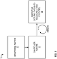
- FIG. 1 is a diagrammatic view of a thread switching system 10 of one implementation.
- thread switching system 10 includes an originating routine 12, a controller routine 14, and a coroutine 16.
- routine as used herein is meant to include a program component, including a function, procedure, or any other manner of grouping source code into a unit.
- An originating routine 12 can be any routine that wants to execute functionality that is contained in a given coroutine, such as coroutine 16.
- the originating routine goes through a controller routine 14.
- the controller routine 14 iteratively calls the coroutine 16 multiple times, each time starting the coroutine 16 on a thread that was indicated by the coroutine when the coroutine returned.
- return statement is meant to include a statement or other mechanism for causing a coroutine to return before an end of the coroutine is reached.
- the return statement is used to return from the routine temporarily so a different thread can be used to process the lines of code that follow.
- the coroutine can indicate the subsequent thread upon returning.
- the return statement can include a return parameter that includes a subsequent thread identifier for the different thread that should be used next.
- Various other ways for indicating the subsequent thread can also be used, such as by the coroutine calling a method to set the subsequent thread before returning, by setting a property or value in an object with the subsequent thread identifier, by recording the subsequent thread identifier to a database, etc.
- the coroutine 16 is then resumed (on the different thread) at the line of code following the return statement (one or more lines later), or at another suitable location.
- the stages can be repeated until the end of the coroutine 16 is reached, or another event happens that causes the controller routine 14 to stop iterating through execution of the coroutine 16 and switching threads.
- a most recent subsequent thread that was indicated in a most recent return from the coroutine can be used to determine the thread to use.
- routine 12 and controller routine 14 can be combined into the same routine.
- routine as used herein can also include coroutines.
- originating routine 12 and controller routine 14 are both described as routines, in some implementations, either or both could be implemented as one or more coroutines.
- computing device 100 In its most basic configuration, computing device 100 typically includes at least one processing unit 102 and memory 104. Depending on the exact configuration and type of computing device, memory 104 may be volatile (such as RAM), non-volatile (such as ROM, flash memory, etc.) or some combination of the two. This most basic configuration is illustrated in Figure 2 by dashed line 106.
- device 100 may also have additional features/functionality.
- device 100 may also include additional storage (removable and/or non-removable) including, but not limited to, magnetic or optical disks or tape.
- additional storage is illustrated in Figure 2 by removable storage 108 and non-removable storage 110.
- Computer storage media includes volatile and nonvolatile, removable and non-removable media implemented in any method or technology for storage of information such as computer readable instructions, data structures, program modules or other data.
- Memory 104, removable storage 108 and non-removable storage 110 are all examples of computer storage media.
- Computer storage media includes, but is not limited to, RAM, ROM, EEPROM, flash memory or other memory technology, CD-ROM, digital versatile disks (DVD) or other optical storage, magnetic cassettes, magnetic tape, magnetic disk storage or other magnetic storage devices, or any other medium which can be used to store the desired information and which can accessed by device 100. Any such computer storage media may be part of device 100.
- Computing device 100 includes one or more communication connections 114 that allow computing device 100 to communicate with other computers/ applications 115.
- Device 100 may also have input device(s) 112 such as keyboard, mouse, pen, voice input device, touch input device, etc.
- Output device(s) 111 such as a display, speakers, printer, etc. may also be included. These devices are well known in the art and need not be discussed at length here.
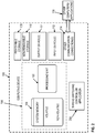
- computing device 100 includes thread switching controller application 200. Thread switching controller application 200 will be described in further detail in Figure 3 .
- Thread switching controller application 200 is one of the application programs that reside on computing device 100. However, it will be understood that thread switching controller application 200 can alternatively or additionally be embodied as computer-executable instructions on one or more computers and/or in different variations than shown on Figure 2 . Alternatively or additionally, one or more parts of thread switching controller application 200 can be part of system memory 104, on other computers and/or applications 115, or other such variations as would occur to one in the computer software art.
- Thread switching controller application 200 includes program logic 204, which is responsible for carrying out some or all of the techniques described herein.
- Program logic 204 includes logic for receiving a request from the originating routine to execute a coroutine 206 (as described below with respect to Figure 4 ); logic for executing the coroutine on an initial thread 208 (as described below with respect to Figure 4 ); logic for receiving a response back from the coroutine when the coroutine returns 210 (as described below with respect to Figure 4 ); logic for executing the coroutine on a subsequent thread indicated when the coroutine returned 212 (as described below with respect to Figure 4 ); logic for enabling graphical user interface logic and worker thread logic to be co-mingled into a single routine 214 (as described below with respect to Figure 6 ); and other logic 220 for operating the thread switching controller application 200.
- Figures 4-6 With continued reference to Figures 1-3 , the stages for implementing one or more implementations of thread switching system 10 (of Figure 1 ) and/or thread switching controller application 200 (of Figure 3 ) are described in further detail. In some implementations, the processes of Figure 4-6 are at least partially implemented in the operating logic of computing device 100.
- Figure 4 is a process flow diagram 240 that illustrates one implementation of the stages involved in using controller routine to manage execution of a coroutine on different threads.
- Figure 4 describes an exemplary process involved in having the controller routine call the coroutine multiple times, each time calling the coroutine on a thread that was specified when the coroutine returned based upon a return statement.
- the controller routine executes the coroutine on an initial thread (stage 244).
- the initial thread will simply be a default thread that is used by the software application when a thread is not otherwise specified.
- the coroutine then executes some logic, and the controller routine receives a response back from the coroutine based upon a return statement (stage 246).
- the coroutine had indicated a subsequent thread identifier to specify what thread the coroutine should be called on the next time the controller routine calls the coroutine.
- the response received back from the coroutine from the return statement contains a parameter with the subsequent thread identifier.
- the controller routine accesses the value in an object, database, or other variable that was assigned the subsequent thread identifier when the coroutine returned.
- the controller routine then executes the coroutine a subsequent time on the thread that was indicated when the coroutine returned (i.e. indicated in the subsequent thread identifier) (stage 248). If the coroutine returns again before the end of the coroutine is reached (i.e. because of another return statement) (decision point 250), then the controller routine will receive another response back from the coroutine and will have an indication of the next subsequent thread to start the coroutine on the next time it is called (stage 246). The controller routine will then execute the coroutine again on the next subsequent thread (stage 248). Once the end of the coroutine is reached (decision point 250), the controller routine stops calling the coroutine (stage 252).
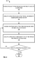
- Figure 5 is a process flow diagram 270 that illustrates one implementation of the stages involved switching threads partially through a routine.
- the routine is started on one thread (stage 272).
- the routine is a coroutine.
- the routine is any type of routine that can be called multiple times, and that is operable to have execution started at a point in the code where the prior execution stopped.
- the routine encounters a return statement, thereby causing the routine to return at a point only partially through all the code in the routine (stage 274).
- the routine causes a subsequent thread identifier to be indicated (stage 274).
- routine can cause the subsequent thread identifier to be indicated, such as in a return parameter of the return statement itself, by setting a property or field of an object or type to set the value, by calling a method that sets the value, by writing the subsequent thread identifier to a database, or through any other means of communicating the subsequent thread identifier to the controller routine.
- Execution of the routine is then resumed on the thread that was specified in the subsequent thread identifier (stage 276). Code execution is picked up where it left off the last time before return, this time on the subsequent thread (stage 278).
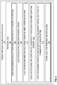
- FIG. 6 is a process flow diagram 290 that illustrates one implementation of the stages involved in enabling graphical user interface thread logic and worker thread logic to be co-mingled into a single routine.
- a coroutine is started on a first thread to receive user input (stage 292). The user input is then received (stage 294). The coroutine returns partially through to switch to a second thread (stage 296), with the second thread being different than the first thread. In one implementation, the coroutine returns because it encountered a return statement. Code execution is resumed in the coroutine on the second thread to do work in response to the user input (stage 298).
- the first thread is a graphical user interface thread
- the second thread is a worker thread.
- Figure 9 shows exemplary source code of co-mingling graphical user interface thread logic and worker thread logic into the same routine.
- exemplary source code 310 is shown for an OnClick event 312 associated with a form of a user interface.
- the OnClick event 312 (originating routine 12 on Figure 1 ) fires when an end user clicks the BetterButton button on the form.
- the OnClick event 312 then calls the controller routine (14 on Figure 1 ), which is the execute method 314 in the example shown.
- the name of the coroutine that needs to be executed by the controller routine is passed as a parameter to the controller routine from the originating routine.
- the controller routine is then responsible for calling the coroutine multiple times on the proper threads, as is indicated in Figure 8 .
- various lines of source code are included for handling work on multiple threads. Calls to the coroutine are also included within a loop 324, which is responsible for calling the coroutine multiple times. Each time the coroutine is called, the controller routine starts the coroutine on the thread that was specified previously when the coroutine returned.
- the coroutine can include code that is designed to be executed on different types of threads mixed into a single coroutine.
- graphical user interface logic (336 and 344) and worker thread logic (340) are co-mingled together into a single routine, which is the betterButton1_Clicked routine 332 in this example.
- return statements (334, 338, and 342) are used.
- GUI threads and worker threads are used for executing separate parts of work.
- the return statement is a yield statement (for the C# programming language).
- Each return statement (334, 338, and 342) signals that the coroutine should be returned temporarily and then resumed in the thread specified as a parameter to the return statement (e.g. "ThreadRequest.UI” for the GUI thread, or "ThreadRequest. Worker” for the worker thread).
- the controller routine shown in Figure 8 receives the return response from the coroutine, the execution of the coroutine is then started again by the controller routine, but on the specified thread.
Landscapes
- Engineering & Computer Science (AREA)
- Software Systems (AREA)
- Theoretical Computer Science (AREA)
- Physics & Mathematics (AREA)
- General Engineering & Computer Science (AREA)
- General Physics & Mathematics (AREA)
- Debugging And Monitoring (AREA)
- Stored Programmes (AREA)
- Executing Machine-Instructions (AREA)
- User Interface Of Digital Computer (AREA)
Description
- Developers write software applications using one or more software development programs. Developers write source code that is needed to make the software application perform the desired functionality. Software applications that have a user interface allow an end user to interact with graphical menus and options in the completed application to achieve a desired result. Source code generally has to be written by developers during development of the software application to handle such user input, and then to perform the proper work in response to the user input.
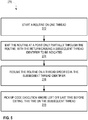
- For example, in the case of a completed customer service application, the end user might be able to select a search operation to search for all customer records for a given customer name. The software application would then have to process the search, access a database to find the matching records, and return the results to the end user. If such a search is processed on the user interface thread of the software application, then an hourglass may or may not be displayed depending on the status of the processing. For example, an hourglass may not be displayed if the application is completely blocked. In such a blocking scenario, all that may be displayed on the screen is a black rectangle or other indicator which designates that the user interface thread is blocked. During this blocked period, the user is not able to do anything else with the program since the user interface thread is totally occupied in the performance of the search.
- As technology has advanced, multi-threaded applications and multiprocessor computers can now be utilized. In other words, multiple threads of execution can be started at the same time, sometimes on multiple processors when available. One thread, for example, may be used to handle user input, and another thread may be used for performing worker tasks. In order to create multi-threaded applications, developers are challenged with writing complex source code that creates and manages the multiple threads. This source code typically needs to include functionality for passing arguments between the different threads, which may be running asynchronously over many different locations. Developers often write separate routines for the work that needs performed by separate threads. Due to the complexity of working with multiple threads, it is common for developers to use the multiple threads incorrectly or inefficiently, or to not even use multiple threads at all and just expect that users will be fine with infrequent user interface blocks.
- Ana Lúcia de Moura et al. "Revisiting Coroutines", June 4, 2004, describes coroutines as a general control abstraction. After proposing a new classification of coroutines, a concept of full asymmetric coroutines and a precise definition for it through an operational semantics is described. Lua coroutine facilities implement a concept of full asymmetric coroutines. Three basic operations are provided: create, resume and yield. These functions are packed in a global table (table coroutine). Function coroutine.create allocates a separate Lua stack for the new coroutine. It receives as argument a Lua function that represents the main body of the coroutine and returns the coroutine reference (a value of type thread).
- Joseph Albahari et al. "C# 3.0 In a Nutshell", 3rd Edition, chapter 19, September 26, 2007 describes a C# program that starts in a single thread that is created automatically by the CLR and operating system (the "main" thread). Here it lives out its life as a single-threaded application, by creating more threads (directly or indirectly). The simplest way to create a thread is to instantiate a Thread object and to call its Start method. The constructor for Thread takes a ThreadStart delegate; a parameterless method indicating where execution should begin. Whenever a thread is started, a few hundred microseconds are spent organizing such things as a fresh private local variable stack. Each thread also consumes around 1 MB of memory. The thread pool cuts these overheads by sharing and recycling threads. The easiest way into a thread pool is by calling ThreadPool.QueueUserWorkItem instead of instantiating and starting a Thread object.
- It is the object of the present invention to provide a method of switching threads within routines.
- This object is achieved by the subject-matter of the independent claims.
- Embodiments are defined by the dependent claims.
- Various technologies and techniques are disclosed for switching threads within routines. A controller routine receives a request from an originating routine to execute a coroutine, and executes the coroutine on an initial thread. The controller routine receives a response back from the coroutine when the coroutine exits based upon a return statement. A subsequent thread is indicated that the coroutine should be executed on when the coroutine is executed a subsequent time. The controller routine executes the coroutine the subsequent time on the subsequent thread that was previously indicated. Multiple return statements can be included in the coroutine, and these steps can be repeated multiple times to switch threads.
- In one implementation, execution of graphical user interface logic and worker thread logic can be co-mingled into a single coroutine. Code execution starts for initial logic contained in a coroutine, with the initial logic being executed on a first thread to receive user input. The user input is then received. The coroutine returns partially through to switch to a second thread, with the second thread being a different thread than the first thread. Code execution resumes in the coroutine on the second thread to perform work in response to the user input.
- This Summary was provided to introduce a selection of concepts in a simplified form that are further described below in the Detailed Description. This Summary is not intended to identify key features or essential features of the claimed subject matter, nor is it intended to be used as an aid in determining the scope of the claimed subject matter.
-
-
Figure 1 is a diagrammatic view of a thread switching system of one implementation. -
Figure 2 is a diagrammatic view of a computer system of one implementation. -
Figure 3 is a diagrammatic view of a thread switching controller application of one implementation. -
Figure 4 is a process flow diagram for one implementation illustrating the stages involved in using a controller routine to manage execution of a coroutine on different threads. -
Figure 5 is a process flow diagram for one implementation illustrating the stages involved in switching threads partially through a routine. -
Figure 6 is a process flow diagram for one implementation illustrating the stages involved in enabling graphical user interface logic and worker thread logic to be co-mingled into a single routine. -
Figure 7 illustrates exemplary source code for an OnClick event associated with a form of a user interface to show an example of how a controller routine is started. -
Figure 8 illustrates exemplary source code for a controller routine that manages the execution of a coroutine on multiple threads. -
Figure 9 illustrates exemplary source code for a coroutine that co-mingles graphical user interface logic and worker thread logic into a single coroutine. - The technologies and techniques herein may be described in the general context as techniques that enable switching between threads within a single routine, but the technologies and techniques also serve other purposes in addition to these. In one implementation, one or more of the techniques described herein can be implemented as features within a software development program such as MICROSOFT® VISUAL STUDIO®, from any type of program or service that is used to write source code for a software application, or from any other type of program or service that is used to create or manage multi-threaded software applications.
- In one implementation, coroutines can be used with some or all of the technologies and techniques described herein to enable code to be written that appears to be sequential and passes arguments with a regular language syntax, but that also allows for switching between multiple threads that execute the logic contained in the single routine. In other words, the technologies and techniques described herein provide mechanisms for co-mingling the usage of logic that is to be executed on different threads within a same routine. The term "coroutine" as used herein is meant to include a function, procedure, or other routine that contains a set of code statements that are co-located within the coroutine and allows multiple entry points that can be suspended and resumed at later times, with the lifetime of a particular activation record of the coroutine being independent of the time when control enters or leaves the coroutine
-
Figure 1 is a diagrammatic view of athread switching system 10 of one implementation. In one implementation,thread switching system 10 includes anoriginating routine 12, acontroller routine 14, and a coroutine 16. The term "routine" as used herein is meant to include a program component, including a function, procedure, or any other manner of grouping source code into a unit. An originating routine 12 can be any routine that wants to execute functionality that is contained in a given coroutine, such as coroutine 16. In one implementation, in order to call the coroutine, the originating routine goes through acontroller routine 14. Thecontroller routine 14 iteratively calls the coroutine 16 multiple times, each time starting the coroutine 16 on a thread that was indicated by the coroutine when the coroutine returned. The term "return statement" as used herein is meant to include a statement or other mechanism for causing a coroutine to return before an end of the coroutine is reached. In other words, when the coroutine 16 wishes to switch threads before executing any more lines of code, the return statement is used to return from the routine temporarily so a different thread can be used to process the lines of code that follow. There are various ways that the coroutine can indicate the subsequent thread upon returning. In one implementation, the return statement can include a return parameter that includes a subsequent thread identifier for the different thread that should be used next. Various other ways for indicating the subsequent thread can also be used, such as by the coroutine calling a method to set the subsequent thread before returning, by setting a property or value in an object with the subsequent thread identifier, by recording the subsequent thread identifier to a database, etc. - The coroutine 16 is then resumed (on the different thread) at the line of code following the return statement (one or more lines later), or at another suitable location. The stages can be repeated until the end of the coroutine 16 is reached, or another event happens that causes the
controller routine 14 to stop iterating through execution of the coroutine 16 and switching threads. In one implementation, each time the coroutine 16 is resumed by thecontroller routine 14, a most recent subsequent thread that was indicated in a most recent return from the coroutine can be used to determine the thread to use. - It should be noted that in another implementation, the functionality of the originating
routine 12 and thecontroller routine 14 can be combined into the same routine. In some implementations, the term "routine" as used herein can also include coroutines. For example, while originating routine 12 andcontroller routine 14 are both described as routines, in some implementations, either or both could be implemented as one or more coroutines. These techniques introduced in the discussion ofFigure 1 will be described in much greater detail inFigures 3-6 , and then with source code examples inFigures 7-9 . - Turning now to
Figure 2 , an exemplary computer system to use for implementing one or more parts of the system is shown that includes a computing device, such ascomputing device 100. In its most basic configuration,computing device 100 typically includes at least oneprocessing unit 102 andmemory 104. Depending on the exact configuration and type of computing device,memory 104 may be volatile (such as RAM), non-volatile (such as ROM, flash memory, etc.) or some combination of the two. This most basic configuration is illustrated inFigure 2 by dashedline 106. - Additionally,
device 100 may also have additional features/functionality. For example,device 100 may also include additional storage (removable and/or non-removable) including, but not limited to, magnetic or optical disks or tape. Such additional storage is illustrated inFigure 2 byremovable storage 108 andnon-removable storage 110. Computer storage media includes volatile and nonvolatile, removable and non-removable media implemented in any method or technology for storage of information such as computer readable instructions, data structures, program modules or other data.Memory 104,removable storage 108 andnon-removable storage 110 are all examples of computer storage media. Computer storage media includes, but is not limited to, RAM, ROM, EEPROM, flash memory or other memory technology, CD-ROM, digital versatile disks (DVD) or other optical storage, magnetic cassettes, magnetic tape, magnetic disk storage or other magnetic storage devices, or any other medium which can be used to store the desired information and which can accessed bydevice 100. Any such computer storage media may be part ofdevice 100. -
Computing device 100 includes one ormore communication connections 114 that allowcomputing device 100 to communicate with other computers/applications 115.Device 100 may also have input device(s) 112 such as keyboard, mouse, pen, voice input device, touch input device, etc. Output device(s) 111 such as a display, speakers, printer, etc. may also be included. These devices are well known in the art and need not be discussed at length here. In one implementation,computing device 100 includes thread switchingcontroller application 200. Thread switchingcontroller application 200 will be described in further detail inFigure 3 . - Turning now to
Figure 3 with continued reference toFigure 2 , a thread switchingcontroller application 200 operating oncomputing device 100 is illustrated. Thread switchingcontroller application 200 is one of the application programs that reside oncomputing device 100. However, it will be understood that thread switchingcontroller application 200 can alternatively or additionally be embodied as computer-executable instructions on one or more computers and/or in different variations than shown onFigure 2 . Alternatively or additionally, one or more parts of thread switchingcontroller application 200 can be part ofsystem memory 104, on other computers and/orapplications 115, or other such variations as would occur to one in the computer software art. - Thread switching
controller application 200 includesprogram logic 204, which is responsible for carrying out some or all of the techniques described herein.Program logic 204 includes logic for receiving a request from the originating routine to execute a coroutine 206 (as described below with respect toFigure 4 ); logic for executing the coroutine on an initial thread 208 (as described below with respect toFigure 4 ); logic for receiving a response back from the coroutine when the coroutine returns 210 (as described below with respect toFigure 4 ); logic for executing the coroutine on a subsequent thread indicated when the coroutine returned 212 (as described below with respect toFigure 4 ); logic for enabling graphical user interface logic and worker thread logic to be co-mingled into a single routine 214 (as described below with respect toFigure 6 ); andother logic 220 for operating the thread switchingcontroller application 200. - Turning now to
Figures 4-6 with continued reference toFigures 1-3 , the stages for implementing one or more implementations of thread switching system 10 (ofFigure 1 ) and/or thread switching controller application 200 (ofFigure 3 ) are described in further detail. In some implementations, the processes ofFigure 4-6 are at least partially implemented in the operating logic ofcomputing device 100. -
Figure 4 is a process flow diagram 240 that illustrates one implementation of the stages involved in using controller routine to manage execution of a coroutine on different threads. In general,Figure 4 describes an exemplary process involved in having the controller routine call the coroutine multiple times, each time calling the coroutine on a thread that was specified when the coroutine returned based upon a return statement. - When a request is received from an originating routine to execute a coroutine (stage 242), the controller routine executes the coroutine on an initial thread (stage 244). In one implementation, before a line of code is encountered in the coroutine to initiate the switching to a desired thread, the initial thread will simply be a default thread that is used by the software application when a thread is not otherwise specified. The coroutine then executes some logic, and the controller routine receives a response back from the coroutine based upon a return statement (stage 246). Upon exit, the coroutine had indicated a subsequent thread identifier to specify what thread the coroutine should be called on the next time the controller routine calls the coroutine. In one implementation, the response received back from the coroutine from the return statement contains a parameter with the subsequent thread identifier. In other implementations, the controller routine accesses the value in an object, database, or other variable that was assigned the subsequent thread identifier when the coroutine returned.
- The controller routine then executes the coroutine a subsequent time on the thread that was indicated when the coroutine returned (i.e. indicated in the subsequent thread identifier) (stage 248). If the coroutine returns again before the end of the coroutine is reached (i.e. because of another return statement) (decision point 250), then the controller routine will receive another response back from the coroutine and will have an indication of the next subsequent thread to start the coroutine on the next time it is called (stage 246). The controller routine will then execute the coroutine again on the next subsequent thread (stage 248). Once the end of the coroutine is reached (decision point 250), the controller routine stops calling the coroutine (stage 252).
-
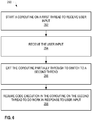
Figure 5 is a process flow diagram 270 that illustrates one implementation of the stages involved switching threads partially through a routine. The routine is started on one thread (stage 272). In one implementation, the routine is a coroutine. In another implementation, the routine is any type of routine that can be called multiple times, and that is operable to have execution started at a point in the code where the prior execution stopped. After executing one or more lines of code in the routine, the routine encounters a return statement, thereby causing the routine to return at a point only partially through all the code in the routine (stage 274). Upon returning, the routine causes a subsequent thread identifier to be indicated (stage 274). There are various ways that the routine can cause the subsequent thread identifier to be indicated, such as in a return parameter of the return statement itself, by setting a property or field of an object or type to set the value, by calling a method that sets the value, by writing the subsequent thread identifier to a database, or through any other means of communicating the subsequent thread identifier to the controller routine. Execution of the routine is then resumed on the thread that was specified in the subsequent thread identifier (stage 276). Code execution is picked up where it left off the last time before return, this time on the subsequent thread (stage 278). -
Figure 6 is a process flow diagram 290 that illustrates one implementation of the stages involved in enabling graphical user interface thread logic and worker thread logic to be co-mingled into a single routine. A coroutine is started on a first thread to receive user input (stage 292). The user input is then received (stage 294). The coroutine returns partially through to switch to a second thread (stage 296), with the second thread being different than the first thread. In one implementation, the coroutine returns because it encountered a return statement. Code execution is resumed in the coroutine on the second thread to do work in response to the user input (stage 298). In one implementation, the first thread is a graphical user interface thread, and the second thread is a worker thread. Various thread combinations are possible, instead of or in addition to graphical user interface threads and/or worker threads.Figure 9 shows exemplary source code of co-mingling graphical user interface thread logic and worker thread logic into the same routine. - Turning now to
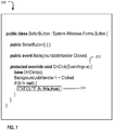
Figures 7-9 , exemplary source code will be described to illustrate the stages ofFigures 4-6 in further detail. Beginning withFigure 7 ,exemplary source code 310 is shown for anOnClick event 312 associated with a form of a user interface. The OnClick event 312 (originating routine 12 onFigure 1 ) fires when an end user clicks the BetterButton button on the form. TheOnClick event 312 then calls the controller routine (14 onFigure 1 ), which is the executemethod 314 in the example shown. In one implementation, the name of the coroutine that needs to be executed by the controller routine is passed as a parameter to the controller routine from the originating routine. The controller routine is then responsible for calling the coroutine multiple times on the proper threads, as is indicated inFigure 8 . In the exemplary controller routine 322 shown inFigure 8 , various lines of source code are included for handling work on multiple threads. Calls to the coroutine are also included within aloop 324, which is responsible for calling the coroutine multiple times. Each time the coroutine is called, the controller routine starts the coroutine on the thread that was specified previously when the coroutine returned. - As shown in
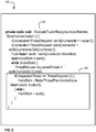
Figure 9 , the coroutine can include code that is designed to be executed on different types of threads mixed into a single coroutine. In theexemplary source code 330 ofFigure 9 , graphical user interface logic (336 and 344) and worker thread logic (340) are co-mingled together into a single routine, which is the betterButton1_Clicked routine 332 in this example. In order to switch between threads, return statements (334, 338, and 342) are used. In this example, GUI threads and worker threads are used for executing separate parts of work. Furthermore, in this example, the return statement is a yield statement (for the C# programming language). Each return statement (334, 338, and 342) signals that the coroutine should be returned temporarily and then resumed in the thread specified as a parameter to the return statement (e.g. "ThreadRequest.UI" for the GUI thread, or "ThreadRequest. Worker" for the worker thread). When the controller routine shown inFigure 8 receives the return response from the coroutine, the execution of the coroutine is then started again by the controller routine, but on the specified thread. - The following is a list of further preferred embodiments of the invention:
- Embodiment 1: A computer-readable medium having computer-executable instructions for causing a computer to perform steps comprising:
- receiving a request from an originating routine to execute a coroutine (206);
- executing the coroutine on an initial thread (208);
- receiving a response back from the coroutine when the coroutine returns based upon a return statement (210); and
- executing the coroutine a subsequent time on a subsequent thread that was indicated by the coroutine upon return (212).
- Embodiment 2: The computer-readable medium of embodiment 1, further having computer-executable instructions for causing a computer to perform steps comprising:
- executing the coroutine a plurality of times until an end of the coroutine is reached, each time executing the coroutine on a most recent subsequent thread indicated by the coroutine upon a most recent return (250).
- Embodiment 3: The computer-readable medium of embodiment 1, wherein the subsequent thread is contained as a parameter to the return statement (246).
- Embodiment 4: The computer-readable medium of embodiment 1, wherein the subsequent thread is used for processing worker thread logic (296).
- Embodiment 5: A method for switching threads partially through a routine comprising the steps of:
- starting an execution of a routine on a first thread (272);
- exiting the routine at a point partially through the routine due to a first return statement, with the first return statement having a subsequent thread identifier (274);
- resuming code execution of the routine on a subsequent thread specified in the subsequent thread identifier (276); and
- picking up code execution in the routine at a line of code following the first return statement (278).
- Embodiment 6: The method of embodiment 5, wherein at least one of the first thread and the subsequent thread is a thread used for processing graphical user interface logic (292).
- Embodiment 7: The method of embodiment 5, wherein at least one of the first thread and the subsequent thread is a worker thread used for processing worker logic (298).
- Embodiment 8: The method of embodiment 5, wherein the routine is a coroutine (272). Embodiment 9: The method of embodiment 8, wherein the first thread is used to handle a different type of operation than the second thread (298).
- Embodiment 10: The method of embodiment 5, wherein the subsequent thread identifier is contained as a parameter in the return statement (274).
- Embodiment 11: The method of embodiment 5, further comprising:
- repeating the exiting, resuming, and picking up steps a plurality of times until an end of the routine is reached (250).
- Embodiment 12: The method of embodiment 5, wherein a first line of code contained in the routine is the first return statement (334).
- Embodiment 13: The method of
embodiment 12, wherein the first return statement is located at the first line of code so that a first desired thread for execution can be specified in the subsequent thread identifier before further code in the routine is processed (334). - Embodiment 14: A method for co-mingling graphical user interface logic and worker thread logic in a single routine comprising the steps of:
- starting code execution of initial logic contained in a coroutine, the initial logic being executed on a first thread to receive user input (292);
- receiving the user input (294);
- exiting the coroutine partially through to switch to a second thread, the second thread being a different thread than the first thread (296); and
- resuming code execution in the coroutine on the second thread to perform work in response to the user input (298).
- Embodiment 15: The method of
embodiment 14, wherein the exiting step is performed when a return statement is reached (296). - Embodiment 16: The method of embodiment 15, wherein the return statement contains a thread identifier as a parameter to specify a next thread that execution should be resumed on (274).
- Embodiment 17: The method of embodiment 16, wherein a plurality of return statements are contained in the routine to indicate when thread switching should occur (16).
- Embodiment 18: The method of
embodiment 14, wherein the coroutine is called a plurality of times by a controller routine that is responsible for calling the coroutine on a proper thread (14). - Embodiment 19: The method of embodiment 18, wherein the controller routine is called by an originating routine (12).
- Embodiment 20: The method of embodiment 19, wherein the originating routine contains a request to call the coroutine (12).
Claims (15)
- A computer-readable medium having computer-executable instructions for causing a computer to perform steps comprising:receiving a request from an originating routine to execute a coroutine (206);executing the coroutine on an initial thread (208);receiving a response back from the coroutine when the coroutine returns based upon a return statement (210);executing the coroutine a subsequent time on a subsequent thread that was indicated by the coroutine upon return (212); andpicking up code execution in the coroutine at the line of code following the return statement (278).
- The computer-readable medium of claim 1, further having computer-executable instructions for causing a computer to perform steps comprising:executing the coroutine a plurality of times until an end of the coroutine is reached, each time executing the coroutine on a most recent subsequent thread indicated by the coroutine upon a most recent return (250).
- The computer-readable medium of claim 1, wherein the subsequent thread is contained as a parameter to the return statement (246).
- The computer-readable medium of claim 1, wherein the subsequent thread is used for processing worker thread logic (296).
- A method for switching threads within a coroutine comprising the steps of:starting an execution of a coroutine on a first thread (272);exiting the coroutine due to a first return statement, with the first return statement having a subsequent thread identifier (274);resuming code execution of the coroutine on a subsequent thread specified in the subsequent thread identifier (276); andpicking up code execution in the coroutine at the line of code following the first return statement (278).
- The method of claim 5, wherein at least one of the first thread and the subsequent thread is a thread used for processing graphical user interface logic (292).
- The method of claim 5, wherein at least one of the first thread and the subsequent thread is a worker thread used for processing worker logic (298).
- The method of claim 5,
wherein the first thread is used to handle a different type of operation than the second thread (298). - The method of claim 5, wherein the subsequent thread identifier is contained as a parameter in the return statement (274).
- The method of claim 5, further comprising:repeating the exiting, resuming, and picking up steps a plurality of times until an end of the routine is reached (250).
- The method of claim 5, wherein a first line of code contained in the routine is the first return statement (334), and/or
wherein the first return statement is located at the first line of code so that a first desired thread for execution can be specified in the subsequent thread identifier before further code in the routine is processed (334). - The method of claim 5,
wherein the step of starting execution of the coroutine further comprises the steps of starting code execution of initial logic contained in a coroutine, the initial logic being executed on a first thread to receive user input (292);
receiving the user input (294); and
wherein the step of resuming code execution of the coroutine on the subsequent thread further comprises performing work in response to the user input (298). - The method of claim 12,
wherein a plurality of return statements are contained in the routine to indicate when thread switching should occur (16). - The method of claim 12, wherein the coroutine is called a plurality of times by a controller routine that is responsible for calling the coroutine on a proper thread (14), and/or
wherein the controller routine is called by an originating routine (12). - The method of claim 14, wherein an originating routine contains a request to call the coroutine (12).
Applications Claiming Priority (2)
| Application Number | Priority Date | Filing Date | Title |
|---|---|---|---|
| US11/977,593 US8589925B2 (en) | 2007-10-25 | 2007-10-25 | Techniques for switching threads within routines |
| PCT/US2008/080825 WO2009055494A2 (en) | 2007-10-25 | 2008-10-22 | Techniques for switching threads within routines |
Publications (3)
| Publication Number | Publication Date |
|---|---|
| EP2217998A2 EP2217998A2 (en) | 2010-08-18 |
| EP2217998A4 EP2217998A4 (en) | 2014-07-23 |
| EP2217998B1 true EP2217998B1 (en) | 2017-02-22 |
Family
ID=40580367
Family Applications (1)
| Application Number | Title | Priority Date | Filing Date |
|---|---|---|---|
| EP08842012.0A Active EP2217998B1 (en) | 2007-10-25 | 2008-10-22 | Techniques for switching threads within routines |
Country Status (5)
| Country | Link |
|---|---|
| US (3) | US8589925B2 (en) |
| EP (1) | EP2217998B1 (en) |
| JP (1) | JP5315354B2 (en) |
| TW (2) | TWI446262B (en) |
| WO (1) | WO2009055494A2 (en) |
Families Citing this family (18)
| Publication number | Priority date | Publication date | Assignee | Title |
|---|---|---|---|---|
| US8589925B2 (en) | 2007-10-25 | 2013-11-19 | Microsoft Corporation | Techniques for switching threads within routines |
| US8732211B2 (en) | 2011-01-28 | 2014-05-20 | International Business Machines Corporation | Method, computer system, and physical computer storage medium for organizing data into data structures |
| JP6469084B2 (en) * | 2013-04-23 | 2019-02-13 | アビニシオ テクノロジー エルエルシー | Control of tasks performed by computing systems |
| KR20150019349A (en) * | 2013-08-13 | 2015-02-25 | 삼성전자주식회사 | Multiple threads execution processor and its operating method |
| EP3189420B1 (en) | 2014-09-02 | 2023-08-23 | AB Initio Technology LLC | Managing execution state of components in a graph-based program specification for controlling their associated tasks |
| JP6778193B2 (en) * | 2014-09-02 | 2020-10-28 | アビニシオ テクノロジー エルエルシー | Controlling data processing tasks |
| US9933918B2 (en) | 2014-09-02 | 2018-04-03 | Ab Initio Technology Llc | Specifying control and data connections in graph-based programs |
| US9760406B2 (en) | 2014-09-02 | 2017-09-12 | Ab Initio Technology Llc | Controlling data processing tasks |
| SG11201701584SA (en) | 2014-09-02 | 2017-03-30 | Ab Initio Technology Llc | Compiling graph-based program specifications |
| US9552223B2 (en) * | 2014-09-30 | 2017-01-24 | International Business Machines Corporation | Post-return asynchronous code execution |
| CN105447138A (en) * | 2015-11-20 | 2016-03-30 | 北京京东尚科信息技术有限公司 | Method and system for server |
| US10761714B2 (en) * | 2015-11-23 | 2020-09-01 | Google Llc | Recognizing gestures and updating display by coordinator |
| CN108089919B (en) * | 2017-12-21 | 2021-01-15 | 北京云杉世纪网络科技有限公司 | Method and system for concurrently processing API (application program interface) requests |
| US11789741B2 (en) * | 2018-03-08 | 2023-10-17 | Sap Se | Determining an optimum quantity of interleaved instruction streams of defined coroutines |
| CN109257411B (en) * | 2018-07-31 | 2021-12-24 | 平安科技(深圳)有限公司 | Service processing method, call management system and computer equipment |
| CN110247984B (en) * | 2019-06-27 | 2022-02-22 | 腾讯科技(深圳)有限公司 | Service processing method, device and storage medium |
| CN113608843B (en) * | 2021-07-08 | 2023-08-25 | 广东开放大学(广东理工职业学院) | Coroutine implementation method and system |
| CN114584500B (en) * | 2022-02-25 | 2024-03-22 | 网易(杭州)网络有限公司 | Asynchronous communication testing method and device and electronic equipment |
Family Cites Families (27)
| Publication number | Priority date | Publication date | Assignee | Title |
|---|---|---|---|---|
| DE69024753T2 (en) * | 1989-10-31 | 1996-05-30 | Hewlett Packard Co | Portable, resource-sharing file server that uses common routines |
| JPH03173938A (en) | 1989-11-30 | 1991-07-29 | Pioneer Electron Corp | Tracking servo device |
| JP2535631B2 (en) * | 1989-12-01 | 1996-09-18 | 富士通株式会社 | Calling call control method |
| US5261097A (en) * | 1991-03-11 | 1993-11-09 | Digital Equipment Corporation | Computer system and method for executing command scripts using multiple synchronized threads |
| US6598068B1 (en) * | 1996-01-04 | 2003-07-22 | Sun Microsystems, Inc. | Method and apparatus for automatically managing concurrent access to a shared resource in a multi-threaded programming environment |
| US6480818B1 (en) * | 1998-11-13 | 2002-11-12 | Cray Inc. | Debugging techniques in a multithreaded environment |
| US6449614B1 (en) | 1999-03-25 | 2002-09-10 | International Business Machines Corporation | Interface system and method for asynchronously updating a share resource with locking facility |
| US7043725B1 (en) * | 1999-07-09 | 2006-05-09 | Hewlett-Packard Development Company, L.P. | Two tier arrangement for threads support in a virtual machine |
| AU7606301A (en) | 2000-09-29 | 2002-04-11 | International Business Machines Corporation | Context based view design to support client side multi-threading |
| US6954933B2 (en) * | 2000-10-30 | 2005-10-11 | Microsoft Corporation | Method and apparatus for providing and integrating high-performance message queues in a user interface environment |
| US6904597B2 (en) | 2001-03-30 | 2005-06-07 | Intel Corporation | Inter-thread communications between different components using double buffer |
| US7007244B2 (en) | 2001-04-20 | 2006-02-28 | Microsoft Corporation | Method and system for displaying categorized information on a user interface |
| US7159215B2 (en) * | 2001-06-27 | 2007-01-02 | Sun Microsystems, Inc. | Termination detection for shared-memory parallel programs |
| US7103887B2 (en) * | 2001-06-27 | 2006-09-05 | Sun Microsystems, Inc. | Load-balancing queues employing LIFO/FIFO work stealing |
| US20030041139A1 (en) | 2001-08-14 | 2003-02-27 | Smartpipes, Incorporated | Event management for a remote network policy management system |
| US7086049B2 (en) * | 2002-02-26 | 2006-08-01 | International Business Machines Corporation | Background code update for embedded systems |
| US7587721B2 (en) * | 2004-05-20 | 2009-09-08 | Sap Ag | Sharing objects in runtime systems |
| JP4520788B2 (en) * | 2004-07-29 | 2010-08-11 | 富士通株式会社 | Multithreaded processor |
| US20060048106A1 (en) * | 2004-08-27 | 2006-03-02 | International Business Machines Corporation | Link-time profile-based method for reducing run-time image of executables |
| US8568225B2 (en) | 2004-09-16 | 2013-10-29 | Bally Gaming, Inc. | User interface system and method for creating and verifying signed content |
| US7685574B2 (en) * | 2004-09-29 | 2010-03-23 | Microsoft Corporation | Constrained execution regions |
| US7603673B2 (en) * | 2004-10-28 | 2009-10-13 | Intel Corporation | Method and system for reducing context switch times |
| US7610579B2 (en) * | 2004-12-10 | 2009-10-27 | Microsoft Corporation | Critical finalizers |
| US7467272B2 (en) * | 2004-12-16 | 2008-12-16 | International Business Machines Corporation | Write protection of subroutine return addresses |
| US7784051B2 (en) * | 2005-11-18 | 2010-08-24 | Sap Ag | Cooperative scheduling using coroutines and threads |
| US20080168247A1 (en) * | 2007-01-05 | 2008-07-10 | Seagate Technology Llc | Method and apparatus for controlling access to a data storage device |
| US8589925B2 (en) | 2007-10-25 | 2013-11-19 | Microsoft Corporation | Techniques for switching threads within routines |
-
2007
- 2007-10-25 US US11/977,593 patent/US8589925B2/en active Active
-
2008
- 2008-09-26 TW TW097137253A patent/TWI446262B/en not_active IP Right Cessation
- 2008-09-26 TW TW103108713A patent/TWI515655B/en not_active IP Right Cessation
- 2008-10-22 EP EP08842012.0A patent/EP2217998B1/en active Active
- 2008-10-22 WO PCT/US2008/080825 patent/WO2009055494A2/en active Application Filing
- 2008-10-22 JP JP2010531211A patent/JP5315354B2/en active Active
-
2013
- 2013-10-21 US US14/059,278 patent/US10007551B2/en active Active
-
2018
- 2018-06-26 US US16/018,427 patent/US10698726B2/en active Active
Non-Patent Citations (1)
| Title |
|---|
| None * |
Also Published As
| Publication number | Publication date |
|---|---|
| WO2009055494A3 (en) | 2009-07-02 |
| EP2217998A4 (en) | 2014-07-23 |
| US20190138347A1 (en) | 2019-05-09 |
| WO2009055494A2 (en) | 2009-04-30 |
| US20090113436A1 (en) | 2009-04-30 |
| TWI446262B (en) | 2014-07-21 |
| US10007551B2 (en) | 2018-06-26 |
| US20140047446A1 (en) | 2014-02-13 |
| TW201426546A (en) | 2014-07-01 |
| TW200921509A (en) | 2009-05-16 |
| US10698726B2 (en) | 2020-06-30 |
| JP5315354B2 (en) | 2013-10-16 |
| US8589925B2 (en) | 2013-11-19 |
| TWI515655B (en) | 2016-01-01 |
| EP2217998A2 (en) | 2010-08-18 |
| JP2011501323A (en) | 2011-01-06 |
Similar Documents
| Publication | Publication Date | Title |
|---|---|---|
| EP2217998B1 (en) | Techniques for switching threads within routines | |
| JP2520543B2 (en) | Method and system for managing program execution | |
| KR101522150B1 (en) | Selective enabling of multi-input controls | |
| US20040199927A1 (en) | Enhanced runtime hosting | |
| US7502968B2 (en) | Automated hang detection in java thread dumps | |
| US20080120605A1 (en) | Stepping and application state viewing between points | |
| US20060059486A1 (en) | Call stack capture in an interrupt driven architecture | |
| US8359604B2 (en) | Propagating unobserved exceptions in a parallel system | |
| JP2010003057A (en) | Processor, performance profiling device, performance profiling program, and performance profiling method | |
| US8468528B2 (en) | Method for selective flushing logs within multiple queues concurrently | |
| TWI488120B (en) | Method and computer-readable storage medium for debugging transaction | |
| US9417914B2 (en) | Regaining control of a processing resource that executes an external execution context | |
| US7596780B2 (en) | System and method for virtual catching of an exception | |
| US8146085B2 (en) | Concurrent exception handling using an aggregated exception structure | |
| US20080098368A1 (en) | Automatic native generation | |
| US5483633A (en) | Method and apparatus for surfacing an object based upon forthcoming criteria | |
| US8806180B2 (en) | Task execution and context switching in a scheduler | |
| US9304831B2 (en) | Scheduling execution contexts with critical regions | |
| EP2176761A1 (en) | Object model for transactional memory | |
| CN112905267B (en) | Method, device and equipment for accessing virtual machine to coroutine library | |
| JPH0822401A (en) | Method for interrupting program execution and debugging device |
Legal Events
| Date | Code | Title | Description |
|---|---|---|---|
| PUAI | Public reference made under article 153(3) epc to a published international application that has entered the european phase |
Free format text: ORIGINAL CODE: 0009012 |
|
| 17P | Request for examination filed |
Effective date: 20100519 |
|
| AK | Designated contracting states |
Kind code of ref document: A2 Designated state(s): AT BE BG CH CY CZ DE DK EE ES FI FR GB GR HR HU IE IS IT LI LT LU LV MC MT NL NO PL PT RO SE SI SK TR |
|
| AX | Request for extension of the european patent |
Extension state: AL BA MK RS |
|
| DAX | Request for extension of the european patent (deleted) | ||
| A4 | Supplementary search report drawn up and despatched |
Effective date: 20140623 |
|
| RIC1 | Information provided on ipc code assigned before grant |
Ipc: G06F 9/38 20060101AFI20140616BHEP Ipc: G06F 9/44 20060101ALI20140616BHEP Ipc: G06F 9/48 20060101ALI20140616BHEP |
|
| RAP1 | Party data changed (applicant data changed or rights of an application transferred) |
Owner name: MICROSOFT TECHNOLOGY LICENSING, LLC |
|
| 17Q | First examination report despatched |
Effective date: 20160107 |
|
| GRAP | Despatch of communication of intention to grant a patent |
Free format text: ORIGINAL CODE: EPIDOSNIGR1 |
|
| INTG | Intention to grant announced |
Effective date: 20160907 |
|
| GRAS | Grant fee paid |
Free format text: ORIGINAL CODE: EPIDOSNIGR3 |
|
| GRAA | (expected) grant |
Free format text: ORIGINAL CODE: 0009210 |
|
| AK | Designated contracting states |
Kind code of ref document: B1 Designated state(s): AT BE BG CH CY CZ DE DK EE ES FI FR GB GR HR HU IE IS IT LI LT LU LV MC MT NL NO PL PT RO SE SI SK TR |
|
| REG | Reference to a national code |
Ref country code: GB Ref legal event code: FG4D |
|
| REG | Reference to a national code |
Ref country code: CH Ref legal event code: EP |
|
| REG | Reference to a national code |
Ref country code: AT Ref legal event code: REF Ref document number: 869748 Country of ref document: AT Kind code of ref document: T Effective date: 20170315 |
|
| REG | Reference to a national code |
Ref country code: IE Ref legal event code: FG4D |
|
| REG | Reference to a national code |
Ref country code: DE Ref legal event code: R096 Ref document number: 602008048858 Country of ref document: DE |
|
| REG | Reference to a national code |
Ref country code: NL Ref legal event code: FP |
|
| REG | Reference to a national code |
Ref country code: LT Ref legal event code: MG4D |
|
| REG | Reference to a national code |
Ref country code: AT Ref legal event code: MK05 Ref document number: 869748 Country of ref document: AT Kind code of ref document: T Effective date: 20170222 |
|
| PG25 | Lapsed in a contracting state [announced via postgrant information from national office to epo] |
Ref country code: GR Free format text: LAPSE BECAUSE OF FAILURE TO SUBMIT A TRANSLATION OF THE DESCRIPTION OR TO PAY THE FEE WITHIN THE PRESCRIBED TIME-LIMIT Effective date: 20170523 Ref country code: HR Free format text: LAPSE BECAUSE OF FAILURE TO SUBMIT A TRANSLATION OF THE DESCRIPTION OR TO PAY THE FEE WITHIN THE PRESCRIBED TIME-LIMIT Effective date: 20170222 Ref country code: NO Free format text: LAPSE BECAUSE OF FAILURE TO SUBMIT A TRANSLATION OF THE DESCRIPTION OR TO PAY THE FEE WITHIN THE PRESCRIBED TIME-LIMIT Effective date: 20170522 Ref country code: FI Free format text: LAPSE BECAUSE OF FAILURE TO SUBMIT A TRANSLATION OF THE DESCRIPTION OR TO PAY THE FEE WITHIN THE PRESCRIBED TIME-LIMIT Effective date: 20170222 Ref country code: LT Free format text: LAPSE BECAUSE OF FAILURE TO SUBMIT A TRANSLATION OF THE DESCRIPTION OR TO PAY THE FEE WITHIN THE PRESCRIBED TIME-LIMIT Effective date: 20170222 |
|
| PG25 | Lapsed in a contracting state [announced via postgrant information from national office to epo] |
Ref country code: BG Free format text: LAPSE BECAUSE OF FAILURE TO SUBMIT A TRANSLATION OF THE DESCRIPTION OR TO PAY THE FEE WITHIN THE PRESCRIBED TIME-LIMIT Effective date: 20170522 Ref country code: SE Free format text: LAPSE BECAUSE OF FAILURE TO SUBMIT A TRANSLATION OF THE DESCRIPTION OR TO PAY THE FEE WITHIN THE PRESCRIBED TIME-LIMIT Effective date: 20170222 Ref country code: ES Free format text: LAPSE BECAUSE OF FAILURE TO SUBMIT A TRANSLATION OF THE DESCRIPTION OR TO PAY THE FEE WITHIN THE PRESCRIBED TIME-LIMIT Effective date: 20170222 Ref country code: PT Free format text: LAPSE BECAUSE OF FAILURE TO SUBMIT A TRANSLATION OF THE DESCRIPTION OR TO PAY THE FEE WITHIN THE PRESCRIBED TIME-LIMIT Effective date: 20170622 Ref country code: AT Free format text: LAPSE BECAUSE OF FAILURE TO SUBMIT A TRANSLATION OF THE DESCRIPTION OR TO PAY THE FEE WITHIN THE PRESCRIBED TIME-LIMIT Effective date: 20170222 Ref country code: LV Free format text: LAPSE BECAUSE OF FAILURE TO SUBMIT A TRANSLATION OF THE DESCRIPTION OR TO PAY THE FEE WITHIN THE PRESCRIBED TIME-LIMIT Effective date: 20170222 |
|
| REG | Reference to a national code |
Ref country code: FR Ref legal event code: PLFP Year of fee payment: 10 |
|
| PG25 | Lapsed in a contracting state [announced via postgrant information from national office to epo] |
Ref country code: EE Free format text: LAPSE BECAUSE OF FAILURE TO SUBMIT A TRANSLATION OF THE DESCRIPTION OR TO PAY THE FEE WITHIN THE PRESCRIBED TIME-LIMIT Effective date: 20170222 Ref country code: RO Free format text: LAPSE BECAUSE OF FAILURE TO SUBMIT A TRANSLATION OF THE DESCRIPTION OR TO PAY THE FEE WITHIN THE PRESCRIBED TIME-LIMIT Effective date: 20170222 Ref country code: SK Free format text: LAPSE BECAUSE OF FAILURE TO SUBMIT A TRANSLATION OF THE DESCRIPTION OR TO PAY THE FEE WITHIN THE PRESCRIBED TIME-LIMIT Effective date: 20170222 Ref country code: IT Free format text: LAPSE BECAUSE OF FAILURE TO SUBMIT A TRANSLATION OF THE DESCRIPTION OR TO PAY THE FEE WITHIN THE PRESCRIBED TIME-LIMIT Effective date: 20170222 Ref country code: CZ Free format text: LAPSE BECAUSE OF FAILURE TO SUBMIT A TRANSLATION OF THE DESCRIPTION OR TO PAY THE FEE WITHIN THE PRESCRIBED TIME-LIMIT Effective date: 20170222 |
|
| REG | Reference to a national code |
Ref country code: DE Ref legal event code: R097 Ref document number: 602008048858 Country of ref document: DE |
|
| PG25 | Lapsed in a contracting state [announced via postgrant information from national office to epo] |
Ref country code: DK Free format text: LAPSE BECAUSE OF FAILURE TO SUBMIT A TRANSLATION OF THE DESCRIPTION OR TO PAY THE FEE WITHIN THE PRESCRIBED TIME-LIMIT Effective date: 20170222 Ref country code: PL Free format text: LAPSE BECAUSE OF FAILURE TO SUBMIT A TRANSLATION OF THE DESCRIPTION OR TO PAY THE FEE WITHIN THE PRESCRIBED TIME-LIMIT Effective date: 20170222 |
|
| PLBE | No opposition filed within time limit |
Free format text: ORIGINAL CODE: 0009261 |
|
| STAA | Information on the status of an ep patent application or granted ep patent |
Free format text: STATUS: NO OPPOSITION FILED WITHIN TIME LIMIT |
|
| 26N | No opposition filed |
Effective date: 20171123 |
|
| PG25 | Lapsed in a contracting state [announced via postgrant information from national office to epo] |
Ref country code: SI Free format text: LAPSE BECAUSE OF FAILURE TO SUBMIT A TRANSLATION OF THE DESCRIPTION OR TO PAY THE FEE WITHIN THE PRESCRIBED TIME-LIMIT Effective date: 20170222 |
|
| PG25 | Lapsed in a contracting state [announced via postgrant information from national office to epo] |
Ref country code: MC Free format text: LAPSE BECAUSE OF FAILURE TO SUBMIT A TRANSLATION OF THE DESCRIPTION OR TO PAY THE FEE WITHIN THE PRESCRIBED TIME-LIMIT Effective date: 20170222 |
|
| REG | Reference to a national code |
Ref country code: CH Ref legal event code: PL |
|
| REG | Reference to a national code |
Ref country code: IE Ref legal event code: MM4A |
|
| PG25 | Lapsed in a contracting state [announced via postgrant information from national office to epo] |
Ref country code: LI Free format text: LAPSE BECAUSE OF NON-PAYMENT OF DUE FEES Effective date: 20171031 Ref country code: CH Free format text: LAPSE BECAUSE OF NON-PAYMENT OF DUE FEES Effective date: 20171031 Ref country code: LU Free format text: LAPSE BECAUSE OF NON-PAYMENT OF DUE FEES Effective date: 20171022 |
|
| REG | Reference to a national code |
Ref country code: BE Ref legal event code: MM Effective date: 20171031 |
|
| PG25 | Lapsed in a contracting state [announced via postgrant information from national office to epo] |
Ref country code: BE Free format text: LAPSE BECAUSE OF NON-PAYMENT OF DUE FEES Effective date: 20171031 |
|
| REG | Reference to a national code |
Ref country code: FR Ref legal event code: PLFP Year of fee payment: 11 |
|
| PG25 | Lapsed in a contracting state [announced via postgrant information from national office to epo] |
Ref country code: MT Free format text: LAPSE BECAUSE OF NON-PAYMENT OF DUE FEES Effective date: 20171022 |
|
| PG25 | Lapsed in a contracting state [announced via postgrant information from national office to epo] |
Ref country code: IE Free format text: LAPSE BECAUSE OF NON-PAYMENT OF DUE FEES Effective date: 20171022 |
|
| PG25 | Lapsed in a contracting state [announced via postgrant information from national office to epo] |
Ref country code: HU Free format text: LAPSE BECAUSE OF FAILURE TO SUBMIT A TRANSLATION OF THE DESCRIPTION OR TO PAY THE FEE WITHIN THE PRESCRIBED TIME-LIMIT; INVALID AB INITIO Effective date: 20081022 |
|
| PG25 | Lapsed in a contracting state [announced via postgrant information from national office to epo] |
Ref country code: CY Free format text: LAPSE BECAUSE OF NON-PAYMENT OF DUE FEES Effective date: 20170222 |
|
| PG25 | Lapsed in a contracting state [announced via postgrant information from national office to epo] |
Ref country code: TR Free format text: LAPSE BECAUSE OF FAILURE TO SUBMIT A TRANSLATION OF THE DESCRIPTION OR TO PAY THE FEE WITHIN THE PRESCRIBED TIME-LIMIT Effective date: 20170222 |
|
| PG25 | Lapsed in a contracting state [announced via postgrant information from national office to epo] |
Ref country code: IS Free format text: LAPSE BECAUSE OF FAILURE TO SUBMIT A TRANSLATION OF THE DESCRIPTION OR TO PAY THE FEE WITHIN THE PRESCRIBED TIME-LIMIT Effective date: 20170622 |
|
| P01 | Opt-out of the competence of the unified patent court (upc) registered |
Effective date: 20230523 |
|
| PGFP | Annual fee paid to national office [announced via postgrant information from national office to epo] |
Ref country code: NL Payment date: 20230922 Year of fee payment: 16 Ref country code: GB Payment date: 20230920 Year of fee payment: 16 |
|
| PGFP | Annual fee paid to national office [announced via postgrant information from national office to epo] |
Ref country code: FR Payment date: 20230920 Year of fee payment: 16 |
|
| PGFP | Annual fee paid to national office [announced via postgrant information from national office to epo] |
Ref country code: DE Payment date: 20230920 Year of fee payment: 16 |