EP2217957B1 - Fiber optic cable connector - Google Patents
Fiber optic cable connector Download PDFInfo
- Publication number
- EP2217957B1 EP2217957B1 EP08850852.8A EP08850852A EP2217957B1 EP 2217957 B1 EP2217957 B1 EP 2217957B1 EP 08850852 A EP08850852 A EP 08850852A EP 2217957 B1 EP2217957 B1 EP 2217957B1
- Authority
- EP
- European Patent Office
- Prior art keywords
- fiber optic
- optic cable
- cable contact
- zone
- contact
- Prior art date
- Legal status (The legal status is an assumption and is not a legal conclusion. Google has not performed a legal analysis and makes no representation as to the accuracy of the status listed.)
- Not-in-force
Links
- 239000000835 fiber Substances 0.000 title claims description 184
- 230000004888 barrier function Effects 0.000 claims description 51
- 238000002788 crimping Methods 0.000 claims description 19
- 230000002093 peripheral effect Effects 0.000 claims description 7
- 239000000463 material Substances 0.000 claims description 6
- 239000013307 optical fiber Substances 0.000 description 64
- 239000002184 metal Substances 0.000 description 17
- 238000000034 method Methods 0.000 description 10
- 230000008569 process Effects 0.000 description 8
- 238000004519 manufacturing process Methods 0.000 description 6
- 230000003287 optical effect Effects 0.000 description 5
- 230000008901 benefit Effects 0.000 description 4
- 230000006378 damage Effects 0.000 description 3
- 238000010438 heat treatment Methods 0.000 description 2
- 238000002844 melting Methods 0.000 description 2
- 230000008018 melting Effects 0.000 description 2
- 238000005498 polishing Methods 0.000 description 2
- 230000009467 reduction Effects 0.000 description 2
- 230000002787 reinforcement Effects 0.000 description 2
- 238000010276 construction Methods 0.000 description 1
- 238000001816 cooling Methods 0.000 description 1
- 230000008878 coupling Effects 0.000 description 1
- 238000010168 coupling process Methods 0.000 description 1
- 238000005859 coupling reaction Methods 0.000 description 1
- 238000013016 damping Methods 0.000 description 1
- 230000001419 dependent effect Effects 0.000 description 1
- 238000009826 distribution Methods 0.000 description 1
- 239000011521 glass Substances 0.000 description 1
- 229910001092 metal group alloy Inorganic materials 0.000 description 1
- 238000007517 polishing process Methods 0.000 description 1
- 238000007493 shaping process Methods 0.000 description 1
- 238000009966 trimming Methods 0.000 description 1
Images


Classifications
-
- G—PHYSICS
- G02—OPTICS
- G02B—OPTICAL ELEMENTS, SYSTEMS OR APPARATUS
- G02B6/00—Light guides; Structural details of arrangements comprising light guides and other optical elements, e.g. couplings
- G02B6/24—Coupling light guides
- G02B6/36—Mechanical coupling means
- G02B6/40—Mechanical coupling means having fibre bundle mating means
- G02B6/403—Mechanical coupling means having fibre bundle mating means of the ferrule type, connecting a pair of ferrules
-
- G—PHYSICS
- G02—OPTICS
- G02B—OPTICAL ELEMENTS, SYSTEMS OR APPARATUS
- G02B6/00—Light guides; Structural details of arrangements comprising light guides and other optical elements, e.g. couplings
- G02B6/24—Coupling light guides
- G02B6/36—Mechanical coupling means
- G02B6/38—Mechanical coupling means having fibre to fibre mating means
- G02B6/3807—Dismountable connectors, i.e. comprising plugs
- G02B6/3833—Details of mounting fibres in ferrules; Assembly methods; Manufacture
- G02B6/3855—Details of mounting fibres in ferrules; Assembly methods; Manufacture characterised by the method of anchoring or fixing the fibre within the ferrule
-
- G—PHYSICS
- G02—OPTICS
- G02B—OPTICAL ELEMENTS, SYSTEMS OR APPARATUS
- G02B6/00—Light guides; Structural details of arrangements comprising light guides and other optical elements, e.g. couplings
- G02B6/24—Coupling light guides
- G02B6/36—Mechanical coupling means
- G02B6/38—Mechanical coupling means having fibre to fibre mating means
- G02B6/3807—Dismountable connectors, i.e. comprising plugs
- G02B6/3833—Details of mounting fibres in ferrules; Assembly methods; Manufacture
- G02B6/3855—Details of mounting fibres in ferrules; Assembly methods; Manufacture characterised by the method of anchoring or fixing the fibre within the ferrule
- G02B6/3857—Crimping, i.e. involving plastic deformation
-
- G—PHYSICS
- G02—OPTICS
- G02B—OPTICAL ELEMENTS, SYSTEMS OR APPARATUS
- G02B6/00—Light guides; Structural details of arrangements comprising light guides and other optical elements, e.g. couplings
- G02B6/24—Coupling light guides
- G02B6/36—Mechanical coupling means
- G02B6/38—Mechanical coupling means having fibre to fibre mating means
- G02B6/3807—Dismountable connectors, i.e. comprising plugs
- G02B6/3833—Details of mounting fibres in ferrules; Assembly methods; Manufacture
- G02B6/3863—Details of mounting fibres in ferrules; Assembly methods; Manufacture fabricated by using polishing techniques
Definitions
- the invention relates to a fiber optic cable contact.
- the invention further relates to a fiber optic cable connector comprising a fiber optic cable contact according to the invention.
- the invention relates to a ready-made fiber optic cable having a fiber optic cable contact according to the invention or a fiber optic cable connector according to the invention, in particular for automotive applications.
- a fiber optic cable connector In order to optically connect an optical fiber or a fiber optic cable via a corresponding connection to a receiver or another fiber optic cable, a fiber optic cable connector is generally provided in which an optical fiber or a bundle of optical fibers is arranged.
- the fiber optic cable connector is configured in such a way that it can be coupled to a corresponding fiber optic cable connector.
- the optical fiber, or bundle of optical fibers hereinafter only a bundle of optical fibers is referred to, however the term optical fiber is to be included herein
- the optical fiber, or bundle of optical fibers which is arranged in the fiber optic cable, converges to contact an optical contact with the receiver, another optical fiber, or another bundle of optical fibers.
- the end surface of the bundle of optical fibers is fabricated to be as planar as possible, in order to create a minimum loss (low damping) optical surface contact between the bundle of optical fibers and a receiver or another bundle of optical fibers.
- a reinforcement sleeve be provided at the end of the bundle of optical fibers.
- the reinforcement sleeve should be made of metal, so that during polishing, a free end of the bundle of optical fibers is ground/polished together with the metal sleeve to be planar. This is carried out, in particular, for bundles of glass optical fibers.
- EP 0 400 856 A1 discloses a method of trimming and melting of optical fibers in a tubular sleeve of a housing of a fiber optic cable connector.
- the melting of the optical fibers takes place in a front half of the tubular sleeve of the housing.
- the massive housing comprises triangular recesses or a groove having a triangular cross-section. Heat transport inside the housing is not a subject matter of the disclosure.
- EP 1 006 376 A1 discloses a metal casing for producing a bundle of optical fibers, wherein the metal casing comprises a thin-walled section for hot-forming and a thick-walled section for fastening the metal casing in a clamping device during hot-forming.
- the thick-walled section comprises a groove. Heat transport inside the housing is not a subject matter of the disclosure.
- An object of the invention is to provide an improved fiber optic cable contact.
- a further object of the invention is to provide an improved fiber optic cable connector and an improved ready-made fiber optic cable comprising a fiber optic cable contact according to the invention.
- the fiber optic cable contact according to the invention should be produced with fewer parts than currently known in the art.
- both a hot forming zone and a zone for fixing a sheathing of the bundle of optical fibers be provided on a single component, in particular the fiber optic cable contact itself.
- the hot forming zone is provided for fixing a longitudinal end portion of a bundle of optical fibers.
- Both the fiber optic cable contact, suitable for a fiber optic cable connector, or a ready-made fiber optic cable are also capable of being produced as quickly, simply and cost-effectively as possible.
- the object of the invention is achieved by a fiber optic cable contact according to claim 1.
- the object of the invention is further achieved by a fiber optic cable connector and a ready-made fiber optic cable comprising a fiber optic cable contact according to the invention according to either claim 8 or claim 9.
- a fiber optic cable contact according to the invention comprises a hot forming zone at a free longitudinal end portion and, at a middle region away from the hot forming zone, a thermal barrier zone and, away from the hot forming zone and away from the thermal barrier zone, a primary locking shoulder.
- the thermal barrier zone is configured in such a way that it prevents heat from passing from the hot forming zone into a portion of the fiber optic cable contact on the other side of the thermal barrier zone during hot forming of the fiber optic cable contact, wherein the thermal barrier zone is provided on/in the fiber optic cable contact adjacent to the hot forming zone, preferably directly adjacent, and is configured as a peripheral thermal stopping groove on/in the fiber optic cable contact, and the thermal barrier zone is provided on/in the fiber optic cable contact between the hot forming zone and a casing-crimping zone of the fiber optic cable contact.
- the thermal barrier zone is provided on/in the fiber optic cable contact, between the hot forming zone and the casing-crimping zone of the fiber optic cable contact, it is possible to reduce the number of parts, which leads to cost benefits. Furthermore, damage to or destruction of a sheathing of the fiber optic cable is prevented because of the reduction in heat to the rest of the fiber optic cable contact. Consequently, the production time is reduced since the hot forming zone can be heated more quickly to a forming temperature.
- the fiber optic cable contact is symmetrical, in particular rotationally symmetrical and/or naturally integral.
- the fiber optic cable contact is preferably a turned, cast or bent part made of metal or a metal alloy.
- the fiber optic cable contact is preferably integral, it may be produced more cheaply and manufactured more quickly, resulting in cost benefits. Furthermore, the fiber optic cable contact is preferably rotationally symmetrical and is also preferably free of any undercut, resulting in quicker production time. In particular, production time is cut when the fiber optic cable contact is produced as a turned or cast part.
- the fiber optic cable contact is constructed to be compatible with the MOST (media oriented systems transport) standard, which is used in the automotive industry.
- MOST media oriented systems transport
- the housing of the MOST product family can be accessed. It is then possible to use both a primary and a secondary locking device (contact lock), where the fiber optic cable contacts are capable being removed in the respective housing.
Landscapes
- Physics & Mathematics (AREA)
- General Physics & Mathematics (AREA)
- Optics & Photonics (AREA)
- Mechanical Coupling Of Light Guides (AREA)
Description
- The invention relates to a fiber optic cable contact. The invention further relates to a fiber optic cable connector comprising a fiber optic cable contact according to the invention. Furthermore, the invention relates to a ready-made fiber optic cable having a fiber optic cable contact according to the invention or a fiber optic cable connector according to the invention, in particular for automotive applications.
- In order to optically connect an optical fiber or a fiber optic cable via a corresponding connection to a receiver or another fiber optic cable, a fiber optic cable connector is generally provided in which an optical fiber or a bundle of optical fibers is arranged. The fiber optic cable connector is configured in such a way that it can be coupled to a corresponding fiber optic cable connector. As a result, the optical fiber, or bundle of optical fibers (hereinafter only a bundle of optical fibers is referred to, however the term optical fiber is to be included herein), which is arranged in the fiber optic cable, converges to contact an optical contact with the receiver, another optical fiber, or another bundle of optical fibers.
- The end surface of the bundle of optical fibers is fabricated to be as planar as possible, in order to create a minimum loss (low damping) optical surface contact between the bundle of optical fibers and a receiver or another bundle of optical fibers. Depending on the material, it is necessary during a polishing process that a reinforcement sleeve be provided at the end of the bundle of optical fibers. In particular, the reinforcement sleeve should be made of metal, so that during polishing, a free end of the bundle of optical fibers is ground/polished together with the metal sleeve to be planar. This is carried out, in particular, for bundles of glass optical fibers.
- The metal sleeve is fixed to the bundle of optical fibers by heating the metal sleeve and the respective longitudinal end portion of the bundle of optical fibers to a forming temperature of the material used for the bundle of optical fibers. Furthermore, a mechanical force is exerted on the metal sleeve and on the longitudinal end portion of the bundle of optical fibers. Consequently, the metal sleeve and the longitudinal end of the bundle of optical fibers are pressed during hot forming of the individual optical fibers into a pack, having a hexagonal (prismatic) to round (cylindrical) cross-section. The metal sleeve preferably forms a fixed connection with the longitudinal end portion of the bundle of optical fibers in order to be able to be subsequently polished.
- In order to optically connect the bundle of optical fibers to a corresponding element (receiver/transmitter, fiber optic cable), it is necessary to provide the bundle of optical fibers in the fiber optic cable connector with a plug-in connector. From a constructional point of view, it is rather complex to arrange the fiber optic cable in a housing of the connector since the housing must cover both the metal sleeve and a sheathing of the bundle of optical fibers, which is provided separately from the metal sleeve. Therefore, the sheathing should first be connected to the metal sleeve before connection to the optic cable connector.
- In order to mechanically connect the sheathing of the bundle of optical fibers to the metal sleeve, it is necessary, according to the state of the art, to use multi-part fiber optic cable contacts for connectors. A one-piece fiber optic cable contact would destroy the sheathing because of the high temperature present when a pack is formed of the metal sleeve and the longitudinal end portion of the bundle of optical fibers.
-
DE 10 2005 043 787 A1 discloses a three-part fiber optic cable contact for connecting a fiber optic cable. A bundle of optical fibers, at a longitudinal end portion, are hot pressed together with a metal sleeve to form a pack, which is then received inside a contact element of the fiber optic cable contact. Further, a clamping element clamps a sheathing of the bundle of optical fibers to the contact element in a portion arranged just behind the contact element. -
EP 0 400 856 A1 discloses a method of trimming and melting of optical fibers in a tubular sleeve of a housing of a fiber optic cable connector. Hereby the melting of the optical fibers takes place in a front half of the tubular sleeve of the housing. Away from the tubular sleeve, the massive housing comprises triangular recesses or a groove having a triangular cross-section. Heat transport inside the housing is not a subject matter of the disclosure. -
EP 1 006 376 A1 - An object of the invention is to provide an improved fiber optic cable contact. A further object of the invention is to provide an improved fiber optic cable connector and an improved ready-made fiber optic cable comprising a fiber optic cable contact according to the invention.
- The fiber optic cable contact according to the invention should be produced with fewer parts than currently known in the art. Preferably, it should be possible that both a hot forming zone and a zone for fixing a sheathing of the bundle of optical fibers be provided on a single component, in particular the fiber optic cable contact itself. The hot forming zone is provided for fixing a longitudinal end portion of a bundle of optical fibers. Furthermore, it should be possible to connect the fiber optic cable to the fiber optic cable contact as quickly, simply and cost-effectively as possible. Both the fiber optic cable contact, suitable for a fiber optic cable connector, or a ready-made fiber optic cable are also capable of being produced as quickly, simply and cost-effectively as possible.
- The object of the invention is achieved by a fiber optic cable contact according to
claim 1. The object of the invention is further achieved by a fiber optic cable connector and a ready-made fiber optic cable comprising a fiber optic cable contact according to the invention according to either claim 8 or claim 9. - A fiber optic cable contact according to the invention comprises a hot forming zone at a free longitudinal end portion and, at a middle region away from the hot forming zone, a thermal barrier zone and, away from the hot forming zone and away from the thermal barrier zone, a primary locking shoulder. The thermal barrier zone is configured in such a way that it prevents heat from passing from the hot forming zone into a portion of the fiber optic cable contact on the other side of the thermal barrier zone during hot forming of the fiber optic cable contact, wherein the thermal barrier zone is provided on/in the fiber optic cable contact adjacent to the hot forming zone, preferably directly adjacent, and is configured as a peripheral thermal stopping groove on/in the fiber optic cable contact, and the thermal barrier zone is provided on/in the fiber optic cable contact between the hot forming zone and a casing-crimping zone of the fiber optic cable contact.
- Since the thermal barrier zone is provided on/in the fiber optic cable contact, between the hot forming zone and the casing-crimping zone of the fiber optic cable contact, it is possible to reduce the number of parts, which leads to cost benefits. Furthermore, damage to or destruction of a sheathing of the fiber optic cable is prevented because of the reduction in heat to the rest of the fiber optic cable contact. Consequently, the production time is reduced since the hot forming zone can be heated more quickly to a forming temperature.
- In preferred embodiments of the invention, the fiber optic cable contact is symmetrical, in particular rotationally symmetrical and/or naturally integral. Furthermore, the fiber optic cable contact is preferably a turned, cast or bent part made of metal or a metal alloy.
- According to the invention, several other advantages result in addition to the advantages mentioned above. Since the fiber optic cable contact is preferably integral, it may be produced more cheaply and manufactured more quickly, resulting in cost benefits. Furthermore, the fiber optic cable contact is preferably rotationally symmetrical and is also preferably free of any undercut, resulting in quicker production time. In particular, production time is cut when the fiber optic cable contact is produced as a turned or cast part.
- In embodiments of the invention, the fiber optic cable contact is constructed to be compatible with the MOST (media oriented systems transport) standard, which is used in the automotive industry. In this context, it may be sufficient for the fiber optic cable contact to have a contour similar to that of a MOST contact. By using this type of contour, the housing of the MOST product family can be accessed. It is then possible to use both a primary and a secondary locking device (contact lock), where the fiber optic cable contacts are capable being removed in the respective housing.
- According to the invention, the thermal barrier zone is connected preferably directly to the hot forming zone on/in the fiber optic cable contact. Consequently, it is possible to limit the heating of the fiber optic cable contact to a forming temperature exclusively, or almost exclusively, to the hot forming zone. In particular, it is possible to reduce the production cycle time for producing the rigid connection between the bundle of optical fibers and the fiber optic cable contact. Furthermore, in preferred embodiments of the invention, the thermal barrier zone is arranged to be remote from the fixing or casing-crimping zone. This region being heated as little as possible through thermal conduction within the fiber optic cable contact, effectively preventing damage to the sheathing.
- In embodiments of the invention, the thermal barrier zone is configured as a channel on/in the fiber optic cable contact. It is preferred that the channel or the groove surround the fiber optic cable contact at least in part, but preferably completely. More particularly, the channel or groove ends should merge into each other, i.e. it is not provided spirally in the fiber optic cable contact. Regarding rigidity, a spiral configuration of the groove is possible, but preferred only if the spiral surrounds the fiber optic cable contact more than once. According to the invention, the configuration of the thermal barrier zone is an annular groove on/in the fiber optic contact. It is then possible to achieve a simple and material-saving embodiment of the fiber optic cable contact, it also being possible for the fiber optic cable contact to be integral.
- In embodiments of the invention, an annular collar is arranged between the thermal barrier zone and the hot forming zone. The diameter of this collar is preferably the same size as the diameter of a portion of the fiber optic cable contact in a region remote from both the hot forming zone and the thermal barrier zone. On the one hand, the fiber optic cable contact is consequently fixed into place in a housing. On the other hand, it is easier to mount a sleeve on the fiber optic cable contact (see also below).
- According to the invention, it is possible to provide or to form one or more thermal barrier zones on/in the fiber optic cable contact. It is possible to provide the thermal barrier zones outside or even inside the fiber optic cable contact. According to the invention, the thermal barrier zone is provided between the hot forming zone and the casing-crimping zone of the fiber optic cable contact. Depending on shape and requirements, the thermal barrier zone is preferably provided as close as possible to the hot forming zone and as far away as possible from the casing-crimping zone on/in the fiber optic cable contact. However, it is also possible in embodiments of the invention to be able to form the thermal barrier zone in the direction of the casing-crimping zone should it be necessary, due to constructional and/or procedural conditions.
- On the one hand, the present invention provides reduction of the fiber optic cable contact cross-section or wall thickness in the region of the thermal barrier zone to such an extent that the rest of the fiber optic cable contact does not become too hot when the hot forming zone is hot formed. On the other hand, the thermal barrier zone should not weaken the fiber optical cable contact in such a manner that it is impossible for the contact to be damaged during hot forming, or during a preceding and subsequent production step and during use.
- According to the invention, the fiber optic cable contact is suitable as a fiber optic cable pin contact. By surrounding the shaped hot forming zone with a sleeve, a fiber optic cable socket contact is produced. By providing the fiber optic cable contact or the fiber optic cable socket contact inside a housing, preferably inside a plastic material housing, a fiber optic cable connector is produced. The fiber optic cable contact or the fiber optic cable connector, and a fiber optic cable form a ready-made fiber optic cable according to the invention.
- Further embodiments of the invention will emerge from the other dependent claims.
- The invention will be explained hereinafter in greater detail with reference to embodiments referring to the appended drawing, in which:
-
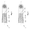
Fig. 1 shows sectional views of a longitudinal end portion of a bundle of optical fibers with a surrounding fiber optic cable contact in a region of a hot forming zone, the sectional views being taken longitudinally and transversely to a longitudinal axis of the fiber optic cable contact after a hot forming process for forming a cylindrical pack; -
Fig. 2 is a view similar to that ofFig. 1 , the hot forming zone of the fiber optic cable contact being hot formed into a prismatic pack; -
Fig. 3 is a perspective view of a fiber optic cable contact according to the invention before the assembly of a fiber optic cable; -
Fig. 4 is a perspective view of the fiber optic cable contact according to the invention after assembly of the fiber optic cable and after the shaping of an end face of the fiber optic cable contact; -
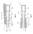
Fig. 5 is a sectional view along the longitudinal axis of a fiber optic cable connector according to the invention with a partial view of a housing; -
Fig. 6 is a sectional view along the longitudinal axis of a fiber optic cable connector according to the invention. - The invention is explained in greater detail hereinafter with reference to a fiber optic cable connector, wherein the fiber optic cable connector is compatible with the MOST(media oriented systems transport) standard. In other words, the fiber optic cable connector makes use of, in particular, an optical coupling for multimedia applications in a motor vehicle, including audio, video, voice and data signals being transferred over a series bus system via optical fibers. However, the invention should not be limited to such a field of application, but may comprise general contacts, contact and bonding means, connectors and the like for fiber optic cables. In this case, the fiber optic cable may comprise a single optical fiber or a bundle of optical fibers, also known as multi-core optical fibers.
- A hot forming process, for producing an optical fiber termination between a fiber
optic cable contact 1 and a bundle ofoptical fibers 200 of afiber optic cable 2, (seeFig. 4 ) is described in more detail with reference toFig. 1 and 2 . In this case,Fig. 1 and 2 show the state of the optical fiber termination after the hot forming process has been carried out, in which loose individual fibers of the bundle ofoptical fibers 200 are rigidly connected to one another to form a compact pack. Hereinafter, the term bundle ofoptical fibers 200 will include the concept of an individualoptical fiber 200. - The
fiber optic cable 2 which is free at a free longitudinal end portion from a sheathing 210 (seeFig. 4 ) is inserted from behind into the inner hollow (seeFig. 5 and 6 ) fiberoptic cable contact 1, the free bundle ofoptical fibers 200 being inserted snugly into a hot formingzone 100 of the fiberoptic cable contact 1. The hot formingzone 100 or the fiberoptic cable contact 1 has enough heat resistance for a forming temperature of the bundle ofoptical fibers 200. - In order to facilitate threading and forwarding of the free bundle of
optical fibers 200 into the hot formingzone 100, the fiberoptic cable contact 1 has, in its inner middle portion, a slightly narrowed contour. In contrast, at its two longitudinal end portions arranged on either side (hot formingzone 100, casing-crimping zone 140), the fiberoptic cable contact 1 preferably has a constant inner diameter which is larger in the region of the casing-crimpingzone 140 than in the region of the hot formingzone 100. - In order to produce the pack, which is formed in the hot forming
zone 100 and the free longitudinal end portion of the bundle ofoptical fibers 200, the hot formingzone 100 or the fiberoptic cable contact 1 is inserted into a mechanical clamping device and thus held in an axial and/or radial direction. Subsequently, the hot formingzone 100, together with the inserted bundle ofoptical fibers 200, is heated to a forming temperature of the optical fibers of the bundle ofoptical fibers 200. In this case, the hot formingzone 100 is preferably heated by means of a forming tool, which may engage with the hot formingzone 100 at an end face and/or laterally. - Consequently, the heated free end portion is deformed in the region of its hot forming
zone 100, during deformation of the optical fibers of the bundle ofoptical fibers 200, to form a pack having an annular cross-section (Fig. 1 ) or a hexagonal cross-section (Fig. 2 ). In this case, an outer contour of the hot formingzone 100 or the fiberoptic cable contact 1 is also correspondingly deformed, resulting in a cylindrical (Fig. 1 ) or a prismatic (Fig. 2 ) pack formed of the hot formingzone 100 and the bundle ofoptical fibers 200. - Lastly, the deformed longitudinal end portion of the bundle of
optical fibers 200 or the fiberoptic cable contact 1 is cooled, preferably still with the forming tool near the hot formingzone 100. After sufficient cooling, the fiberoptic cable contact 1 is formed with the bundle ofoptical fibers 200, which are arranged at the hot formingzone 100 of the contact. It is possible to use the hot forming process to form other front cross-sections of the fiberoptic cable contact 1 and the bundle ofoptical fibers 200 than those shown. - Subsequently, an
end face optic cable contact 1 or the bundle ofoptical fibers 200 is machined and thus brought to a specific length. The specific length of the fiberoptic cable contact 1 is necessary so there is enough space for the contact in a housing 3 (seeFig. 5 ) or so the contact can be inserted far enough into ahousing 3 of a counter plug or into a receptacle of a means or a device. - High temperatures are necessary for processing the bundle of
optical fibers 200. Both, the hot formingzone 100 and the bundle ofoptical fibers 200, are heated to the forming temperature of the optical fibers. Athermal barrier zone 110 is provided, at a suitable location inside the fiberoptic cable contact 1, to negate too much heat from flowing through or passing into the rest of the fiberoptic cable contact 1. - On the one hand, the
thermal barrier zone 110 ensures that the entire fiberoptic cable contact 1 is not heated to the forming temperature during the forming process, preventing energy and production time from being wasted. On the other hand, thethermal barrier zone 110 ensures that thesheathing 210 of thefiber optic cable 2, which can be crimped at the casing-crimpingzone 140 of the fiberoptic cable contact 1, is not damaged during the forming process, i.e. is not melted. - In this case, the
sheathing 210 may be held or fixed between the bundle ofoptical fibers 200 and an inner face of the fiberoptic cable contact 1 by crimping the casing-crimpingzone 140, before or after the forming process. - In an embodiment, shown in
Fig. 3 and4 , the hot forming orhot working zone 100 is provided at a freelongitudinal end portion 10 of the fiberoptic cable contact 1. The freelongitudinal end portion 10 is connected to amiddle region 11 or aregion 11 of the fiberoptic cable contact 1, which is arranged away from the freelongitudinal end portion 10. Optionally, themiddle region 11 may overlap the freelongitudinal end portion 10 in the longitudinal direction L of the fiberoptic cable contact 1. Then, thehousing crimping zone 140 of the fiberoptic cable contact 1 is preferably connected to thismiddle region 11 in the longitudinal direction L, on an opposite side of the middle region to where the freelongitudinal end portion 10 is connected. - The
thermal barrier zone 110 is provided to be preferably adjacent, in particular directly adjacent, to the hot formingzone 100 externally in themiddle region 11 of the fiberoptic cable contact 1. In the present embodiment, the hot formingzone 100 is provided to be adjacent to thethermal barrier zone 110 at a front longitudinal end portion of the fiberoptic cable contact 1, and afront shoulder 112 or afront collar 112 preferably being arranged between thethermal barrier zone 110 and the hot formingzone 100. - In the present embodiment, the
thermal barrier zone 110 is configured as a thermal stop groove or a thermal stop channel surrounding the fiberoptic cable contact 1 at least in part, and is configured so as to be preferably symmetrical or rotational symmetrical. In other words, the peripheral wall thickness of the fiberoptic cable contact 1 is reduced, at least in portions (D-d), in the region of thethermal barrier zone 110 as shown inFig. 5 . - Preferably, the wall thickness d of the fiber
optic cable contact 1 is approximately 15 to 85 %, in particular approximately 25 to 75 %, smaller in a region of thethermal barrier zone 110 than the wall thickness D of the fiberoptic cable contact 1 in a region directly adjacent to thethermal barrier zone 110. Considering the mechanical load of the fiberoptic cable contact 1, there is a limit to the amount of material removed to create the groove in the region of thethermal barrier zone 110. When thethermal barrier zone 110 is configured as a peripheral recess, arear shoulder 114 or arear collar 114 is needed, of which the diameter D preferably corresponds to the diameter D of thefront collar 112. - Further behind the
rear shoulder 114 orcollar 114, in the longitudinal direction L of the fiberoptic cable contact 1, and away from the thermal barrier zone, is aprimary locking zone 120 and attached thereto is asecondary locking zone 130 of the fiberoptic cable contact 1. In this case, it is preferable for therespective locking zones elements Fig. 5 . - A
housing crimping zone 140 is attached to thesecondary locking zone 130, further along the longitudinal direction L of the fiberoptic cable contact 1. Preferably, the fiberoptic cable contact 1 has a constant outer diameter, in the region of thehousing crimping zone 140, which in turn comprise a shoulder or a collar. The outer diameter should preferably correspond to the outer diameter of both the primary 120 and secondary 130 locking zones. - The
zones optic cable contact 1, as well as the configuration of the fiberoptic cable contact 1, in the region of its freelongitudinal end portion 10 and itsmiddle region 11, are arranged depending on the construction of thehousing 3. -
Fig. 4 shows the fiberoptic cable contact 1, with afiber optic cable 2, attached thereto after finishing, both cleaving and polishing operations finish the definedoptical end face zone 100 and crimping (not shown in the figure) of thehousing crimping zone 140, of the fiberoptic cable contact 1. Subsequently, the fiberoptic cable contact 1 may be inserted into thehousing 3, in particular aplastic material housing 3, as is shown in a partial cross-section inFig. 5 . -
Fig. 5 shows the fiberoptic cable contact 1 sectioned in its longitudinal direction L, and locked at its upper side in thehousing 3. In this case, the fiberoptic cable contact 1 is locked in thehousing 3 by the primary 320 and secondary 330 locking elements. Theprimary locking element 320 is configured as a latch inside thehousing 3 in one piece or integrally therewith. Thesecondary locking element 330 is preferably acontact lock 330, which can be inserted externally into thehousing 3. It is also possible to exchange these functions or to configure each of the primary 320 and secondary 330 locking elements each as anintegral latch 320 or each as anexternal contact lock 330. Stop shoulders or the like may be used instead ofnotches 320. -
Fig. 5 also shows a second thermal barrier zone (110). In this case, the reference numeral being placed within brackets in order to clarify that this second thermal barrier zone (110) is optional. In this case, the second thermal barrier zone (110) is in turn provided between the casing-crimpingzone 140 and the hot formingzone 100, or between the casing-crimpingzone 140 and the firstthermal barrier zone 110. Furthermore, the distribution of theindividual zones portions Fig. 5 with curly brackets. In this case, therespective zones portions Fig. 5 a dotted line can be seen at the firstthermal barrier zone 110. -
Fig. 6 shows two further embodiments of the invention. A fiber opticcable socket contact 1 can be produced from the fiberoptic cable contact 1 ofFig. 3 to 5 . For this purpose, asleeve 150 is slid onto the freelongitudinal end portion 10 of the fiberoptic cable contact 1 and fixed thereto. In the process, thesleeve 150 preferably abuts a collar of theprimary locking zone 120. It is particularly preferable in this case for thecollar 112 and thecollar 114 to have the same diameter D (seeFig. 5 ). Thesleeve 150 preferably extends beyond the free end of the fiberoptic cable contact 1 in such a way that the end face thereof 102, 202 is arranged inside the fiber opticcable socket contact 1. -
Fig. 6 further shows a thermal barrier zone (110) arranged inside, which also extends completely inside the fiberoptic cable contact 1 and may also be configured as shown above. This is optional, so the respective reference numeral is given in brackets. It is possible to provide only a single thermal barrier zone (110) that is arranged inside, and to provide no thermal barrier zone (110) outside. - According to the invention, numerous embodiments of the fiber
optic cable contact 1 are possible. The fiberoptic cable contact 1 is preferably a symmetrical, in particular rotationally symmetrical, component, which is preferably a turned, cast or bent part. The fiberoptic cable contact 1 is preferably configured integrally, in particular materially integrally. Furthermore, thesheathing 210 is crimped by means of a four-jaw crimp. It is also possible to produce an asymmetrical or a multi-part fiberoptic cable contact 1 according to the invention. Furthermore, another type of crimp, which is not a four-jaw crimp may also be used.
Claims (9)
- Fiber optic cable contact (1) having a hot forming zone (100) at a free longitudinal end portion (10) and, at a middle region (11) of the fiber optic cable contact (1) away from the hot forming zone (100), a thermal barrier zone (110) and, away from the hot forming zone (100) and away from the thermal barrier zone (110), a primary locking shoulder (120),
the thermal barrier zone (110) being configured in such a way that it prevents heat from passing from the hot forming zone (100) into a portion of the fiber optic cable contact (1) on the other side of the thermal barrier zone (110) during hot forming of the fiber optic cable contact (1), wherein
the thermal barrier zone (110) is provided on/in the fiber optic cable contact (1) adjacent to the hot forming zone (100), preferably directly adjacent, and is configured as a peripheral thermal stopping groove (110) on/in the fiber optic cable contact (1), and the thermal barrier zone (110) is provided on/in the fiber optic cable contact (1) between the hot forming zone (100) and a casing-crimping zone (140) of the fiber optic cable contact (1). - Fiber optic cable contact (1) according to claim 1, wherein the wall thickness (d) of the fiber optic cable contact (1) in a portion of the thermal barrier zone (110) is at least approximately 20 to 30%, preferably approximately 35 to 40%, in particular approximately 45 to 50%, particularly preferably approximately 50 to 55% or, in particular, particularly preferably approximately 70 to 80% thinner than the wall thickness (D) of the fiber optic cable contact (1) in a portion directly adjacent to the thermal barrier zone (110).
- Fiber optic cable contact (1) according to one of claims 1 or 2, wherein a preferably completely peripheral shoulder (112) is formed on/in the fiber optic cable contact (1) between the hot forming zone (100) and the thermal barrier zone (110).
- Fiber optic cable contact (1) according to one of claims 1 to 3, wherein the fiber optic cable contact (1) comprises a plurality of thermal barrier zones (110).
- Fiber optic cable contact (1) according to one of claims 1 to 4, wherein the fiber optic cable contact (1) is configured integrally, preferably materially integrally, in particular as a turned, cast or bent part.
- Fiber optic cable contact (1) according to one of claims 1 to 5, wherein the fiber optic cable contact (1) has a profile, which is compatible with the MOST standard.
- Fiber optic cable contact (1) according to one of claims 1 to 6, wherein the fiber optic cable contact (1) comprises a sleeve (150) at its free longitudinal end portion (10).
- Fiber optic cable connector for automotive applications, comprising a housing (3), preferably a plastic material housing (3), and a fiber optic cable contact (1) according to one of claims 1 to 8 housed therein.
- Ready-made fiber optic cable for automotive applications, comprising a fiber optic cable contact (1) according to one of claims 1 to 7 or a fiber optic cable connector according to claim 8 and a fiber optic cable (2) connected thereto.
Applications Claiming Priority (2)
| Application Number | Priority Date | Filing Date | Title |
|---|---|---|---|
| DE102007054747.3A DE102007054747B4 (en) | 2007-11-16 | 2007-11-16 | Fiber optic cable contact, fiber optic cable connector and ready-made fiber optic cable |
| PCT/EP2008/065161 WO2009062894A1 (en) | 2007-11-16 | 2008-11-07 | Fiber optic cable connector |
Publications (2)
| Publication Number | Publication Date |
|---|---|
| EP2217957A1 EP2217957A1 (en) | 2010-08-18 |
| EP2217957B1 true EP2217957B1 (en) | 2015-04-08 |
Family
ID=40433695
Family Applications (1)
| Application Number | Title | Priority Date | Filing Date |
|---|---|---|---|
| EP08850852.8A Not-in-force EP2217957B1 (en) | 2007-11-16 | 2008-11-07 | Fiber optic cable connector |
Country Status (6)
| Country | Link |
|---|---|
| US (1) | US9423576B2 (en) |
| EP (1) | EP2217957B1 (en) |
| JP (1) | JP2011503655A (en) |
| CN (1) | CN101868746B (en) |
| DE (1) | DE102007054747B4 (en) |
| WO (1) | WO2009062894A1 (en) |
Families Citing this family (11)
| Publication number | Priority date | Publication date | Assignee | Title |
|---|---|---|---|---|
| RU2383041C1 (en) * | 2008-07-21 | 2010-02-27 | Министерство обороны Российской Федерации Государственное образовательное учреждение высшего профессионального образования ВОЕННАЯ АКАДЕМИЯ СВЯЗИ имени С.М. Буденного | Fibre-optic connector |
| US9289191B2 (en) | 2011-10-12 | 2016-03-22 | Seno Medical Instruments, Inc. | System and method for acquiring optoacoustic data and producing parametric maps thereof |
| CN102611719B (en) * | 2011-01-21 | 2017-04-12 | 香港生产力促进局 | Vehicle-mounted MOST network system |
| US20130279920A1 (en) * | 2011-11-02 | 2013-10-24 | Seno Medical Instruments, Inc. | Repeatably alignable fiber optic connector |
| US11191435B2 (en) | 2013-01-22 | 2021-12-07 | Seno Medical Instruments, Inc. | Probe with optoacoustic isolator |
| JP2015509443A (en) | 2012-03-09 | 2015-03-30 | セノ メディカル インストルメンツ,インク. | Statistical mapping in photoacoustic imaging systems |
| US20130343709A1 (en) * | 2012-06-22 | 2013-12-26 | Jeffrey Dean Danley | Ferrule assemblies employing mechanical interfaces for optical fibers, and related components and methods |
| US9880362B2 (en) | 2012-10-22 | 2018-01-30 | Corning Optical Communications LLC | Methods of securing one or more optical fibers to a ferrule |
| JP2019144545A (en) * | 2018-02-15 | 2019-08-29 | 株式会社川島製作所 | Method for producing light guide with terminals, jig and manufacturing apparatus |
| US11787727B2 (en) * | 2018-04-18 | 2023-10-17 | Lawrence Livermore National Security, Llc | Method for fabrication of sleeveless photonic crystal canes with an arbitrary shape |
| WO2022241113A1 (en) * | 2021-05-14 | 2022-11-17 | Senko Advanced Components, Inc. | Optical fiber connector with improved cable retention strength |
Family Cites Families (19)
| Publication number | Priority date | Publication date | Assignee | Title |
|---|---|---|---|---|
| US3051035A (en) | 1960-05-17 | 1962-08-28 | American Optical Corp | Flexible pyroscopes |
| US4116655A (en) * | 1975-07-09 | 1978-09-26 | Elliott Brothers (London) Limited | Method for making optical-fibre cables |
| GB1586467A (en) * | 1976-10-21 | 1981-03-18 | Elliott Brothers London Ltd | Optical fibre terminations |
| FR2385107A1 (en) * | 1977-01-18 | 1978-10-20 | Souriau & Cie | IMPROVEMENTS TO THE METHODS FOR PREPARING, WITH A VIEW TO ITS CONNECTION, AN END OF AN OPTICAL CABLE WITH FIBER HARNESS AND CABLE THUS OBTAINED |
| GB8912356D0 (en) * | 1989-05-30 | 1989-07-12 | Keymed Medicals & Ind Equip | A method of forming a fibre optic terminal assembly |
| US5216735A (en) * | 1989-10-31 | 1993-06-01 | Fibotech, Inc. | Metal core fiberoptic connector plug for single fiber and multiple fiber coupling |
| US5305406A (en) * | 1989-10-31 | 1994-04-19 | Fibotech, Inc. | Fiberoptic connector assembly and method and device for the manufacture thereof |
| US5058985A (en) * | 1990-07-23 | 1991-10-22 | General Electric Company | Coupling means between a light source and a bundle of optical fibers and method of making such coupling means |
| JPH0687904U (en) * | 1993-06-03 | 1994-12-22 | 沖電線株式会社 | Heat resistant fiber optic light guide terminal |
| US6065882A (en) | 1995-07-14 | 2000-05-23 | Cogent Light Technologies, Inc. | Snap-in proximal connector for mounting an optic fiber element into a light source system |
| JPH09293802A (en) * | 1996-04-26 | 1997-11-11 | Toshiba Corp | Semiconductor package |
| US6061490A (en) * | 1997-08-01 | 2000-05-09 | Mitsubishi Rayon Co., Ltd. | Optical fiber bundle with bundling member |
| US6078714A (en) * | 1998-07-30 | 2000-06-20 | The Boeing Company | Fiber optic bundle interface cooling system |
| DE19849026A1 (en) * | 1998-10-23 | 2000-04-27 | Bayerische Motoren Werke Ag | Method for fastening an optical fiber end in a plastic contact sleeve and correspondingly produced plastic contact |
| DE19855958A1 (en) | 1998-12-04 | 2000-06-21 | Schott Glas | Method for producing optical fiber bundles and optical fiber bundles produced according to the same, and device for carrying out the method |
| US7099552B1 (en) * | 2003-02-18 | 2006-08-29 | Kilolambda Technologies Ltd. | Optical terminator |
| US6860645B2 (en) * | 2003-06-26 | 2005-03-01 | Furukawa Electric North America, Inc. | Optical fiber cable connector assembly with strain relief |
| DE102004048741B8 (en) | 2004-10-05 | 2007-02-01 | Schott Ag | Process for making an optical fiber termination |
| DE102005043787B4 (en) | 2005-09-14 | 2007-07-26 | Tyco Electronics Amp Gmbh | contacting |
-
2007
- 2007-11-16 DE DE102007054747.3A patent/DE102007054747B4/en not_active Expired - Fee Related
-
2008
- 2008-11-07 EP EP08850852.8A patent/EP2217957B1/en not_active Not-in-force
- 2008-11-07 WO PCT/EP2008/065161 patent/WO2009062894A1/en not_active Ceased
- 2008-11-07 US US12/734,652 patent/US9423576B2/en not_active Expired - Fee Related
- 2008-11-07 CN CN2008801160674A patent/CN101868746B/en not_active Expired - Fee Related
- 2008-11-07 JP JP2010533546A patent/JP2011503655A/en active Pending
Also Published As
| Publication number | Publication date |
|---|---|
| US20100272400A1 (en) | 2010-10-28 |
| EP2217957A1 (en) | 2010-08-18 |
| JP2011503655A (en) | 2011-01-27 |
| DE102007054747A1 (en) | 2009-07-30 |
| CN101868746A (en) | 2010-10-20 |
| DE102007054747B4 (en) | 2022-05-12 |
| CN101868746B (en) | 2013-08-14 |
| WO2009062894A1 (en) | 2009-05-22 |
| US9423576B2 (en) | 2016-08-23 |
Similar Documents
| Publication | Publication Date | Title |
|---|---|---|
| US9423576B2 (en) | Fiber optic cable connector | |
| US9625660B2 (en) | Cable termination assembly and method for connectors | |
| EP2992372B1 (en) | Connectorized fiber optic cable assembly and method of assembling it | |
| EP2609458B1 (en) | Fiber optic cable assemblies with mechanically interlocking crimp bands and methods of making the assemblies | |
| EP2901189B1 (en) | Ruggedized multi-fiber fiber optic connector with sealed dust cap | |
| US5923804A (en) | Fiber optic connector and an associated method of fabrication | |
| CA2805593C (en) | Fiber optic cable assemblies with fiber access apertures and methods of assembly | |
| EP2857878B1 (en) | Connector housing for securing an optical cable and methods of use and manufacture thereof | |
| US9069140B2 (en) | Optical connector | |
| CN103984060B (en) | The fiber optic cables of Belt connector and optical connector | |
| US20080196451A1 (en) | Apparatus and method for producing an end of an optical fiber bundle and improved optical fiber bundle made with same | |
| EP2068183A1 (en) | Field-installable optical splice | |
| EP3709452A1 (en) | Connector assembly with retainer and method of manufacturing same | |
| EP3504570B1 (en) | Methods of securing an optical fiber within an optical fiber connector using a heating apparatus | |
| EP0674195B1 (en) | An optical waveguide plug | |
| KR100970853B1 (en) | Fiber optic cable connector system | |
| CN108692122B (en) | Pipe comprising a connector and method for operating said pipe | |
| EP2914994B1 (en) | Terminus assembly for terminating an optical cable | |
| US20050226589A1 (en) | Fiber-optic plug comprising crimped knobs | |
| US20210271033A1 (en) | Fiber optic cable assemblies and methods of forming the same | |
| IT201900005080A1 (en) | Fiber optic connector device. |
Legal Events
| Date | Code | Title | Description |
|---|---|---|---|
| PUAI | Public reference made under article 153(3) epc to a published international application that has entered the european phase |
Free format text: ORIGINAL CODE: 0009012 |
|
| 17P | Request for examination filed |
Effective date: 20100427 |
|
| AK | Designated contracting states |
Kind code of ref document: A1 Designated state(s): AT BE BG CH CY CZ DE DK EE ES FI FR GB GR HR HU IE IS IT LI LT LU LV MC MT NL NO PL PT RO SE SI SK TR |
|
| AX | Request for extension of the european patent |
Extension state: AL BA MK RS |
|
| DAX | Request for extension of the european patent (deleted) | ||
| 17Q | First examination report despatched |
Effective date: 20120601 |
|
| GRAP | Despatch of communication of intention to grant a patent |
Free format text: ORIGINAL CODE: EPIDOSNIGR1 |
|
| INTG | Intention to grant announced |
Effective date: 20140613 |
|
| RIN1 | Information on inventor provided before grant (corrected) |
Inventor name: BIEBER, JOERG Inventor name: HAHN, JOACHIM Inventor name: MUELLER, WOLFGANG |
|
| GRAP | Despatch of communication of intention to grant a patent |
Free format text: ORIGINAL CODE: EPIDOSNIGR1 |
|
| GRAS | Grant fee paid |
Free format text: ORIGINAL CODE: EPIDOSNIGR3 |
|
| INTG | Intention to grant announced |
Effective date: 20150211 |
|
| GRAA | (expected) grant |
Free format text: ORIGINAL CODE: 0009210 |
|
| AK | Designated contracting states |
Kind code of ref document: B1 Designated state(s): AT BE BG CH CY CZ DE DK EE ES FI FR GB GR HR HU IE IS IT LI LT LU LV MC MT NL NO PL PT RO SE SI SK TR |
|
| REG | Reference to a national code |
Ref country code: GB Ref legal event code: FG4D |
|
| REG | Reference to a national code |
Ref country code: CH Ref legal event code: EP |
|
| REG | Reference to a national code |
Ref country code: IE Ref legal event code: FG4D |
|
| REG | Reference to a national code |
Ref country code: AT Ref legal event code: REF Ref document number: 720989 Country of ref document: AT Kind code of ref document: T Effective date: 20150515 |
|
| REG | Reference to a national code |
Ref country code: DE Ref legal event code: R096 Ref document number: 602008037620 Country of ref document: DE Effective date: 20150521 |
|
| REG | Reference to a national code |
Ref country code: DE Ref legal event code: R082 Ref document number: 602008037620 Country of ref document: DE Representative=s name: WILHELM & BECK, DE Ref country code: DE Ref legal event code: R081 Ref document number: 602008037620 Country of ref document: DE Owner name: TE CONNECTIVITY GERMANY GMBH, DE Free format text: FORMER OWNER: TYCO ELECTRONICS AMP GMBH, 64625 BENSHEIM, DE |
|
| REG | Reference to a national code |
Ref country code: AT Ref legal event code: MK05 Ref document number: 720989 Country of ref document: AT Kind code of ref document: T Effective date: 20150408 |
|
| REG | Reference to a national code |
Ref country code: NL Ref legal event code: VDEP Effective date: 20150408 |
|
| RAP2 | Party data changed (patent owner data changed or rights of a patent transferred) |
Owner name: TE CONNECTIVITY GERMANY GMBH |
|
| REG | Reference to a national code |
Ref country code: LT Ref legal event code: MG4D |
|
| PG25 | Lapsed in a contracting state [announced via postgrant information from national office to epo] |
Ref country code: NL Free format text: LAPSE BECAUSE OF FAILURE TO SUBMIT A TRANSLATION OF THE DESCRIPTION OR TO PAY THE FEE WITHIN THE PRESCRIBED TIME-LIMIT Effective date: 20150408 |
|
| PG25 | Lapsed in a contracting state [announced via postgrant information from national office to epo] |
Ref country code: HR Free format text: LAPSE BECAUSE OF FAILURE TO SUBMIT A TRANSLATION OF THE DESCRIPTION OR TO PAY THE FEE WITHIN THE PRESCRIBED TIME-LIMIT Effective date: 20150408 Ref country code: ES Free format text: LAPSE BECAUSE OF FAILURE TO SUBMIT A TRANSLATION OF THE DESCRIPTION OR TO PAY THE FEE WITHIN THE PRESCRIBED TIME-LIMIT Effective date: 20150408 Ref country code: PT Free format text: LAPSE BECAUSE OF FAILURE TO SUBMIT A TRANSLATION OF THE DESCRIPTION OR TO PAY THE FEE WITHIN THE PRESCRIBED TIME-LIMIT Effective date: 20150810 Ref country code: FI Free format text: LAPSE BECAUSE OF FAILURE TO SUBMIT A TRANSLATION OF THE DESCRIPTION OR TO PAY THE FEE WITHIN THE PRESCRIBED TIME-LIMIT Effective date: 20150408 Ref country code: LT Free format text: LAPSE BECAUSE OF FAILURE TO SUBMIT A TRANSLATION OF THE DESCRIPTION OR TO PAY THE FEE WITHIN THE PRESCRIBED TIME-LIMIT Effective date: 20150408 Ref country code: NO Free format text: LAPSE BECAUSE OF FAILURE TO SUBMIT A TRANSLATION OF THE DESCRIPTION OR TO PAY THE FEE WITHIN THE PRESCRIBED TIME-LIMIT Effective date: 20150708 |
|
| REG | Reference to a national code |
Ref country code: FR Ref legal event code: PLFP Year of fee payment: 8 |
|
| PG25 | Lapsed in a contracting state [announced via postgrant information from national office to epo] |
Ref country code: LV Free format text: LAPSE BECAUSE OF FAILURE TO SUBMIT A TRANSLATION OF THE DESCRIPTION OR TO PAY THE FEE WITHIN THE PRESCRIBED TIME-LIMIT Effective date: 20150408 Ref country code: GR Free format text: LAPSE BECAUSE OF FAILURE TO SUBMIT A TRANSLATION OF THE DESCRIPTION OR TO PAY THE FEE WITHIN THE PRESCRIBED TIME-LIMIT Effective date: 20150709 Ref country code: AT Free format text: LAPSE BECAUSE OF FAILURE TO SUBMIT A TRANSLATION OF THE DESCRIPTION OR TO PAY THE FEE WITHIN THE PRESCRIBED TIME-LIMIT Effective date: 20150408 Ref country code: IS Free format text: LAPSE BECAUSE OF FAILURE TO SUBMIT A TRANSLATION OF THE DESCRIPTION OR TO PAY THE FEE WITHIN THE PRESCRIBED TIME-LIMIT Effective date: 20150808 |
|
| REG | Reference to a national code |
Ref country code: DE Ref legal event code: R097 Ref document number: 602008037620 Country of ref document: DE |
|
| PG25 | Lapsed in a contracting state [announced via postgrant information from national office to epo] |
Ref country code: EE Free format text: LAPSE BECAUSE OF FAILURE TO SUBMIT A TRANSLATION OF THE DESCRIPTION OR TO PAY THE FEE WITHIN THE PRESCRIBED TIME-LIMIT Effective date: 20150408 Ref country code: DK Free format text: LAPSE BECAUSE OF FAILURE TO SUBMIT A TRANSLATION OF THE DESCRIPTION OR TO PAY THE FEE WITHIN THE PRESCRIBED TIME-LIMIT Effective date: 20150408 |
|
| PLBE | No opposition filed within time limit |
Free format text: ORIGINAL CODE: 0009261 |
|
| STAA | Information on the status of an ep patent application or granted ep patent |
Free format text: STATUS: NO OPPOSITION FILED WITHIN TIME LIMIT |
|
| PG25 | Lapsed in a contracting state [announced via postgrant information from national office to epo] |
Ref country code: SK Free format text: LAPSE BECAUSE OF FAILURE TO SUBMIT A TRANSLATION OF THE DESCRIPTION OR TO PAY THE FEE WITHIN THE PRESCRIBED TIME-LIMIT Effective date: 20150408 Ref country code: PL Free format text: LAPSE BECAUSE OF FAILURE TO SUBMIT A TRANSLATION OF THE DESCRIPTION OR TO PAY THE FEE WITHIN THE PRESCRIBED TIME-LIMIT Effective date: 20150408 Ref country code: RO Free format text: LAPSE BECAUSE OF NON-PAYMENT OF DUE FEES Effective date: 20150408 Ref country code: CZ Free format text: LAPSE BECAUSE OF FAILURE TO SUBMIT A TRANSLATION OF THE DESCRIPTION OR TO PAY THE FEE WITHIN THE PRESCRIBED TIME-LIMIT Effective date: 20150408 |
|
| 26N | No opposition filed |
Effective date: 20160111 |
|
| PG25 | Lapsed in a contracting state [announced via postgrant information from national office to epo] |
Ref country code: SI Free format text: LAPSE BECAUSE OF FAILURE TO SUBMIT A TRANSLATION OF THE DESCRIPTION OR TO PAY THE FEE WITHIN THE PRESCRIBED TIME-LIMIT Effective date: 20150408 |
|
| PG25 | Lapsed in a contracting state [announced via postgrant information from national office to epo] |
Ref country code: LU Free format text: LAPSE BECAUSE OF FAILURE TO SUBMIT A TRANSLATION OF THE DESCRIPTION OR TO PAY THE FEE WITHIN THE PRESCRIBED TIME-LIMIT Effective date: 20151107 Ref country code: MC Free format text: LAPSE BECAUSE OF FAILURE TO SUBMIT A TRANSLATION OF THE DESCRIPTION OR TO PAY THE FEE WITHIN THE PRESCRIBED TIME-LIMIT Effective date: 20150408 |
|
| REG | Reference to a national code |
Ref country code: CH Ref legal event code: PL |
|
| PG25 | Lapsed in a contracting state [announced via postgrant information from national office to epo] |
Ref country code: LI Free format text: LAPSE BECAUSE OF NON-PAYMENT OF DUE FEES Effective date: 20151130 Ref country code: CH Free format text: LAPSE BECAUSE OF NON-PAYMENT OF DUE FEES Effective date: 20151130 |
|
| REG | Reference to a national code |
Ref country code: IE Ref legal event code: MM4A |
|
| PG25 | Lapsed in a contracting state [announced via postgrant information from national office to epo] |
Ref country code: BE Free format text: LAPSE BECAUSE OF FAILURE TO SUBMIT A TRANSLATION OF THE DESCRIPTION OR TO PAY THE FEE WITHIN THE PRESCRIBED TIME-LIMIT Effective date: 20150408 |
|
| PG25 | Lapsed in a contracting state [announced via postgrant information from national office to epo] |
Ref country code: IE Free format text: LAPSE BECAUSE OF NON-PAYMENT OF DUE FEES Effective date: 20151107 |
|
| REG | Reference to a national code |
Ref country code: FR Ref legal event code: PLFP Year of fee payment: 9 |
|
| PG25 | Lapsed in a contracting state [announced via postgrant information from national office to epo] |
Ref country code: HU Free format text: LAPSE BECAUSE OF FAILURE TO SUBMIT A TRANSLATION OF THE DESCRIPTION OR TO PAY THE FEE WITHIN THE PRESCRIBED TIME-LIMIT; INVALID AB INITIO Effective date: 20081107 Ref country code: BG Free format text: LAPSE BECAUSE OF FAILURE TO SUBMIT A TRANSLATION OF THE DESCRIPTION OR TO PAY THE FEE WITHIN THE PRESCRIBED TIME-LIMIT Effective date: 20150408 |
|
| PG25 | Lapsed in a contracting state [announced via postgrant information from national office to epo] |
Ref country code: CY Free format text: LAPSE BECAUSE OF FAILURE TO SUBMIT A TRANSLATION OF THE DESCRIPTION OR TO PAY THE FEE WITHIN THE PRESCRIBED TIME-LIMIT Effective date: 20150408 Ref country code: SE Free format text: LAPSE BECAUSE OF FAILURE TO SUBMIT A TRANSLATION OF THE DESCRIPTION OR TO PAY THE FEE WITHIN THE PRESCRIBED TIME-LIMIT Effective date: 20150408 |
|
| PG25 | Lapsed in a contracting state [announced via postgrant information from national office to epo] |
Ref country code: TR Free format text: LAPSE BECAUSE OF FAILURE TO SUBMIT A TRANSLATION OF THE DESCRIPTION OR TO PAY THE FEE WITHIN THE PRESCRIBED TIME-LIMIT Effective date: 20150408 Ref country code: MT Free format text: LAPSE BECAUSE OF FAILURE TO SUBMIT A TRANSLATION OF THE DESCRIPTION OR TO PAY THE FEE WITHIN THE PRESCRIBED TIME-LIMIT Effective date: 20150408 |
|
| REG | Reference to a national code |
Ref country code: FR Ref legal event code: PLFP Year of fee payment: 10 |
|
| PGFP | Annual fee paid to national office [announced via postgrant information from national office to epo] |
Ref country code: GB Payment date: 20171127 Year of fee payment: 10 |
|
| REG | Reference to a national code |
Ref country code: FR Ref legal event code: PLFP Year of fee payment: 11 |
|
| GBPC | Gb: european patent ceased through non-payment of renewal fee |
Effective date: 20181107 |
|
| PG25 | Lapsed in a contracting state [announced via postgrant information from national office to epo] |
Ref country code: GB Free format text: LAPSE BECAUSE OF NON-PAYMENT OF DUE FEES Effective date: 20181107 |
|
| PGFP | Annual fee paid to national office [announced via postgrant information from national office to epo] |
Ref country code: FR Payment date: 20210930 Year of fee payment: 14 |
|
| PGFP | Annual fee paid to national office [announced via postgrant information from national office to epo] |
Ref country code: DE Payment date: 20210923 Year of fee payment: 14 |
|
| PGFP | Annual fee paid to national office [announced via postgrant information from national office to epo] |
Ref country code: IT Payment date: 20211012 Year of fee payment: 14 |
|
| REG | Reference to a national code |
Ref country code: DE Ref legal event code: R119 Ref document number: 602008037620 Country of ref document: DE |
|
| PG25 | Lapsed in a contracting state [announced via postgrant information from national office to epo] |
Ref country code: IT Free format text: LAPSE BECAUSE OF NON-PAYMENT OF DUE FEES Effective date: 20221107 Ref country code: DE Free format text: LAPSE BECAUSE OF NON-PAYMENT OF DUE FEES Effective date: 20230601 |
|
| PG25 | Lapsed in a contracting state [announced via postgrant information from national office to epo] |
Ref country code: FR Free format text: LAPSE BECAUSE OF NON-PAYMENT OF DUE FEES Effective date: 20221130 |