EP2217847B1 - Energie- und regasifizierungsanlage für lng - Google Patents
Energie- und regasifizierungsanlage für lng Download PDFInfo
- Publication number
- EP2217847B1 EP2217847B1 EP08841311.7A EP08841311A EP2217847B1 EP 2217847 B1 EP2217847 B1 EP 2217847B1 EP 08841311 A EP08841311 A EP 08841311A EP 2217847 B1 EP2217847 B1 EP 2217847B1
- Authority
- EP
- European Patent Office
- Prior art keywords
- condenser
- turbine
- lng
- motive fluid
- supplied
- Prior art date
- Legal status (The legal status is an assumption and is not a legal conclusion. Google has not performed a legal analysis and makes no representation as to the accuracy of the status listed.)
- Active
Links
Images


Classifications
-
- F—MECHANICAL ENGINEERING; LIGHTING; HEATING; WEAPONS; BLASTING
- F01—MACHINES OR ENGINES IN GENERAL; ENGINE PLANTS IN GENERAL; STEAM ENGINES
- F01K—STEAM ENGINE PLANTS; STEAM ACCUMULATORS; ENGINE PLANTS NOT OTHERWISE PROVIDED FOR; ENGINES USING SPECIAL WORKING FLUIDS OR CYCLES
- F01K25/00—Plants or engines characterised by use of special working fluids, not otherwise provided for; Plants operating in closed cycles and not otherwise provided for
- F01K25/08—Plants or engines characterised by use of special working fluids, not otherwise provided for; Plants operating in closed cycles and not otherwise provided for using special vapours
-
- F—MECHANICAL ENGINEERING; LIGHTING; HEATING; WEAPONS; BLASTING
- F17—STORING OR DISTRIBUTING GASES OR LIQUIDS
- F17C—VESSELS FOR CONTAINING OR STORING COMPRESSED, LIQUEFIED OR SOLIDIFIED GASES; FIXED-CAPACITY GAS-HOLDERS; FILLING VESSELS WITH, OR DISCHARGING FROM VESSELS, COMPRESSED, LIQUEFIED, OR SOLIDIFIED GASES
- F17C2221/00—Handled fluid, in particular type of fluid
- F17C2221/03—Mixtures
- F17C2221/032—Hydrocarbons
- F17C2221/033—Methane, e.g. natural gas, CNG, LNG, GNL, GNC, PLNG
-
- F—MECHANICAL ENGINEERING; LIGHTING; HEATING; WEAPONS; BLASTING
- F17—STORING OR DISTRIBUTING GASES OR LIQUIDS
- F17C—VESSELS FOR CONTAINING OR STORING COMPRESSED, LIQUEFIED OR SOLIDIFIED GASES; FIXED-CAPACITY GAS-HOLDERS; FILLING VESSELS WITH, OR DISCHARGING FROM VESSELS, COMPRESSED, LIQUEFIED, OR SOLIDIFIED GASES
- F17C2223/00—Handled fluid before transfer, i.e. state of fluid when stored in the vessel or before transfer from the vessel
- F17C2223/01—Handled fluid before transfer, i.e. state of fluid when stored in the vessel or before transfer from the vessel characterised by the phase
- F17C2223/0107—Single phase
- F17C2223/0123—Single phase gaseous, e.g. CNG, GNC
-
- F—MECHANICAL ENGINEERING; LIGHTING; HEATING; WEAPONS; BLASTING
- F17—STORING OR DISTRIBUTING GASES OR LIQUIDS
- F17C—VESSELS FOR CONTAINING OR STORING COMPRESSED, LIQUEFIED OR SOLIDIFIED GASES; FIXED-CAPACITY GAS-HOLDERS; FILLING VESSELS WITH, OR DISCHARGING FROM VESSELS, COMPRESSED, LIQUEFIED, OR SOLIDIFIED GASES
- F17C2227/00—Transfer of fluids, i.e. method or means for transferring the fluid; Heat exchange with the fluid
- F17C2227/01—Propulsion of the fluid
- F17C2227/0128—Propulsion of the fluid with pumps or compressors
- F17C2227/0135—Pumps
-
- F—MECHANICAL ENGINEERING; LIGHTING; HEATING; WEAPONS; BLASTING
- F17—STORING OR DISTRIBUTING GASES OR LIQUIDS
- F17C—VESSELS FOR CONTAINING OR STORING COMPRESSED, LIQUEFIED OR SOLIDIFIED GASES; FIXED-CAPACITY GAS-HOLDERS; FILLING VESSELS WITH, OR DISCHARGING FROM VESSELS, COMPRESSED, LIQUEFIED, OR SOLIDIFIED GASES
- F17C2227/00—Transfer of fluids, i.e. method or means for transferring the fluid; Heat exchange with the fluid
- F17C2227/01—Propulsion of the fluid
- F17C2227/0128—Propulsion of the fluid with pumps or compressors
- F17C2227/0157—Compressors
-
- F—MECHANICAL ENGINEERING; LIGHTING; HEATING; WEAPONS; BLASTING
- F17—STORING OR DISTRIBUTING GASES OR LIQUIDS
- F17C—VESSELS FOR CONTAINING OR STORING COMPRESSED, LIQUEFIED OR SOLIDIFIED GASES; FIXED-CAPACITY GAS-HOLDERS; FILLING VESSELS WITH, OR DISCHARGING FROM VESSELS, COMPRESSED, LIQUEFIED, OR SOLIDIFIED GASES
- F17C2227/00—Transfer of fluids, i.e. method or means for transferring the fluid; Heat exchange with the fluid
- F17C2227/03—Heat exchange with the fluid
- F17C2227/0302—Heat exchange with the fluid by heating
- F17C2227/0309—Heat exchange with the fluid by heating using another fluid
- F17C2227/0311—Air heating
-
- F—MECHANICAL ENGINEERING; LIGHTING; HEATING; WEAPONS; BLASTING
- F17—STORING OR DISTRIBUTING GASES OR LIQUIDS
- F17C—VESSELS FOR CONTAINING OR STORING COMPRESSED, LIQUEFIED OR SOLIDIFIED GASES; FIXED-CAPACITY GAS-HOLDERS; FILLING VESSELS WITH, OR DISCHARGING FROM VESSELS, COMPRESSED, LIQUEFIED, OR SOLIDIFIED GASES
- F17C2227/00—Transfer of fluids, i.e. method or means for transferring the fluid; Heat exchange with the fluid
- F17C2227/03—Heat exchange with the fluid
- F17C2227/0302—Heat exchange with the fluid by heating
- F17C2227/0309—Heat exchange with the fluid by heating using another fluid
- F17C2227/0316—Water heating
- F17C2227/0318—Water heating using seawater
-
- F—MECHANICAL ENGINEERING; LIGHTING; HEATING; WEAPONS; BLASTING
- F17—STORING OR DISTRIBUTING GASES OR LIQUIDS
- F17C—VESSELS FOR CONTAINING OR STORING COMPRESSED, LIQUEFIED OR SOLIDIFIED GASES; FIXED-CAPACITY GAS-HOLDERS; FILLING VESSELS WITH, OR DISCHARGING FROM VESSELS, COMPRESSED, LIQUEFIED, OR SOLIDIFIED GASES
- F17C2227/00—Transfer of fluids, i.e. method or means for transferring the fluid; Heat exchange with the fluid
- F17C2227/03—Heat exchange with the fluid
- F17C2227/0302—Heat exchange with the fluid by heating
- F17C2227/0309—Heat exchange with the fluid by heating using another fluid
- F17C2227/0323—Heat exchange with the fluid by heating using another fluid in a closed loop
-
- F—MECHANICAL ENGINEERING; LIGHTING; HEATING; WEAPONS; BLASTING
- F17—STORING OR DISTRIBUTING GASES OR LIQUIDS
- F17C—VESSELS FOR CONTAINING OR STORING COMPRESSED, LIQUEFIED OR SOLIDIFIED GASES; FIXED-CAPACITY GAS-HOLDERS; FILLING VESSELS WITH, OR DISCHARGING FROM VESSELS, COMPRESSED, LIQUEFIED, OR SOLIDIFIED GASES
- F17C2227/00—Transfer of fluids, i.e. method or means for transferring the fluid; Heat exchange with the fluid
- F17C2227/03—Heat exchange with the fluid
- F17C2227/0302—Heat exchange with the fluid by heating
- F17C2227/0327—Heat exchange with the fluid by heating with recovery of heat
-
- F—MECHANICAL ENGINEERING; LIGHTING; HEATING; WEAPONS; BLASTING
- F17—STORING OR DISTRIBUTING GASES OR LIQUIDS
- F17C—VESSELS FOR CONTAINING OR STORING COMPRESSED, LIQUEFIED OR SOLIDIFIED GASES; FIXED-CAPACITY GAS-HOLDERS; FILLING VESSELS WITH, OR DISCHARGING FROM VESSELS, COMPRESSED, LIQUEFIED, OR SOLIDIFIED GASES
- F17C2227/00—Transfer of fluids, i.e. method or means for transferring the fluid; Heat exchange with the fluid
- F17C2227/03—Heat exchange with the fluid
- F17C2227/0367—Localisation of heat exchange
- F17C2227/0388—Localisation of heat exchange separate
- F17C2227/0393—Localisation of heat exchange separate using a vaporiser
-
- F—MECHANICAL ENGINEERING; LIGHTING; HEATING; WEAPONS; BLASTING
- F17—STORING OR DISTRIBUTING GASES OR LIQUIDS
- F17C—VESSELS FOR CONTAINING OR STORING COMPRESSED, LIQUEFIED OR SOLIDIFIED GASES; FIXED-CAPACITY GAS-HOLDERS; FILLING VESSELS WITH, OR DISCHARGING FROM VESSELS, COMPRESSED, LIQUEFIED, OR SOLIDIFIED GASES
- F17C2265/00—Effects achieved by gas storage or gas handling
- F17C2265/01—Purifying the fluid
- F17C2265/015—Purifying the fluid by separating
-
- F—MECHANICAL ENGINEERING; LIGHTING; HEATING; WEAPONS; BLASTING
- F17—STORING OR DISTRIBUTING GASES OR LIQUIDS
- F17C—VESSELS FOR CONTAINING OR STORING COMPRESSED, LIQUEFIED OR SOLIDIFIED GASES; FIXED-CAPACITY GAS-HOLDERS; FILLING VESSELS WITH, OR DISCHARGING FROM VESSELS, COMPRESSED, LIQUEFIED, OR SOLIDIFIED GASES
- F17C2265/00—Effects achieved by gas storage or gas handling
- F17C2265/05—Regasification
-
- F—MECHANICAL ENGINEERING; LIGHTING; HEATING; WEAPONS; BLASTING
- F17—STORING OR DISTRIBUTING GASES OR LIQUIDS
- F17C—VESSELS FOR CONTAINING OR STORING COMPRESSED, LIQUEFIED OR SOLIDIFIED GASES; FIXED-CAPACITY GAS-HOLDERS; FILLING VESSELS WITH, OR DISCHARGING FROM VESSELS, COMPRESSED, LIQUEFIED, OR SOLIDIFIED GASES
- F17C2265/00—Effects achieved by gas storage or gas handling
- F17C2265/07—Generating electrical power as side effect
Definitions
- the present invention relates to the field of power generation. More particularly, the invention relates to a system which both utilizes liquefied natural gas for power generation and re-gasifies the liquefied natural gas.
- the transportation of natural gas through pipelines is uneconomic.
- the natural gas is therefore cooled to a temperature below its boiling point, e.g. -160°C, until becoming liquid and the liquefied natural gas (LNG) is subsequently stored in tanks. Since the volume of natural gas is considerably less in liquid phase than in gaseous phase, the LNG can be conveniently and economically transported by ship to destination port.
- LNG liquefied natural gas
- the LNG In the vicinity of the destination port, the LNG is transported to a regasification terminal, whereat it is reheated by heat exchange with sea water or with the exhaust gas of gas turbines and converted into gas.
- Each regasification terminal is usually connected with a distribution network of pipelines so that the regasified natural gas may be transmitted to an end user. While a regasification terminal is efficient in terms of the ability to vaporize the LNG so that it may be transmitted to end users, there is a need for an efficient method for harnessing the cold potential of the LNG as a cold sink for a condenser to generate power.
- a power cycle including a combined cycle power plant and an organic Rankine cycle power plant using the condenser of the steam turbine as its heat source is disclosed in US Patent No. 5,687,570 , and US2006/0236699 . It is an object of the present invention to provide an LNG-based power and regasification system, which utilizes the low temperature of the LNG as a cold sink for the condenser of the power system in order to generate electricity or produce power for direct use.
- the present invention provides a power and regasification system based on liquefied natural gas (LNG), comprising a vaporizer by which liquid motive fluid is vaporized, said liquid motive fluid being LNG or a motive fluid liquefied by means of LNG; a turbine for expanding the vaporized motive fluid and producing power; heat exchanger means to which expanded motive fluid vapor is supplied, said heat exchanger means also being supplied with LNG for receiving heat from said expanded fluid vapor, whereby the temperature of the LNG increases as it flows through the heat exchanger means; a conduit through which said motive fluid is circulated from at least the inlet of said vaporizer to the outlet of said heat exchanger means; and a line for transmitting regasified LNG.
- LNG liquefied natural gas
- the heat source of the vaporizer may be sea water at a temperature ranging between approximately 5°C to 20°C or heat such as an exhaust gas discharged from a gas turbine or low pressure steam exiting a condensing steam turbine.
- the system further comprises a pump for delivering liquid motive fluid to the vaporizer.
- the system may further comprise a compressor for compressing regasified LNG and transmitting said compressed regasified LNG along a pipeline to end users.
- the compressor may be coupled to the turbine.
- the regasified LNG may also be transmitted via the line to storage.
- the power system is a closed Rankine cycle power system such that the conduit further extends from the outlet of the heat exchanger means to the inlet of the vaporizer and the heat exchanger means is a condenser by which the LNG condenses the motive fluid exhausted from the turbine to a temperature ranging from approximately -90°C to -120°C.
- the motive fluid is preferably organic fluid such as ethane, ethene or methane or equivalents, or a mixture of propane and ethane or equivalents.
- the temperature of the LNG heated by the turbine exhaust is preferably further increased by means of a heater.
- the present invention provides a closed organic Rankine cycle power and regasification system for liquefied natural gas (LNG), comprising:
- the power system is an open cycle power system
- the motive fluid is LNG
- the heat exchanger means is a heater for re-gasifying the LNG exhausted from the turbine.
- the heat source of the heater may be sea water at a temperature ranging between approximately 5°C to 20°C or waste heat such as an exhaust gas discharged from a gas turbine.
- the present invention is a power and regasification system based on liquid natural gas (LNG). While transported LNG, e.g. mostly methane, is vaporized in the prior art at a regasification terminal by being passed through a heat exchanger, wherein sea water or another heat source e.g. the exhaust of a gas turbine heats the LNG above its boiling point, an efficient method for utilizing the cold LNG to produce power is needed.
- LNG liquid natural gas
- sea water or another heat source e.g. the exhaust of a gas turbine heats the LNG above its boiling point
- an efficient method for utilizing the cold LNG to produce power is needed.
- the cold temperature potential of the LNG serves as a cold sink of a power cycle. Electricity or power is generated due to the large temperature differential between the cold LNG and the heat source, e.g. sea water.
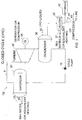
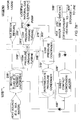
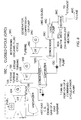
- Figs. 1 and 2 illustrate a system wherein cold LNG serves as the cold sink medium in the condenser of a closed Rankine cycle power plant.
- Fig. 1 is a schematic arrangement of the power system and
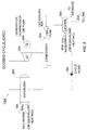
- Fig. 2 is a temperature-entropy diagram of the closed cycle.
- the power system of a closed Rankine cycle is generally designated as numeral 10.
- Organic fluid such as ethane, ethene or methane or an equivalent, is the preferred motive fluid for power system 10 and circulates through conduits 8.
- Pump 15 delivers liquid organic fluid at state A, the temperature of which ranges from about -80°C to -120°C, to vaporizer 20 at state B .
- Sea water in line 18 at an average temperature of approximately 520°C introduced to vaporizer 20 serves to transfer heat to the motive fluid passing therethrough (i.e. from state B to state C).
- the temperature of the motive fluid consequently rises above its boiling point to a temperature of approximately - 10 to 0°C, and the vaporized motive fluid produced is supplied to turbine 25.
- the sea water discharged from vaporizer 20 via line 19 is returned to the ocean.
- power or preferably electricity is produced by generator 28 operated to turbine 25.
- turbine 25 rotates at about 1500 RPM or 1800 RPM.
- LNG in line 32 at an average temperature of approximately -160°C introduced to condenser 30 serves to condense the motive fluid exiting turbine 25 (i.e. from state D to state A) corresponding to a liquid phase, so that pump 15 delivers the liquid motive fluid to vaporizer 20. Since the LNG lowers the temperature of the motive fluid to a considerably low temperature of about -80°C to -120°C, the recoverable energy available by expanding the vaporized motive fluid in turbine 25 is relatively high.
- the temperature of LNG in line 32 increases after heat is transferred thereto within condenser 30 by the expanded motive fluid exiting turbine 25, and is further increased by sea water, which is passed through heater 36 via line 37. Sea water discharged from heater 36 via line 38 is returned to the ocean.
- the temperature of the sea water introduced into heater 35 is usually sufficient to re-gasify the LNG, which may held in storage vessel 42 or, alternatively, be compressed and delivered by compressor 45 through line 43 to a pipeline for distribution of vaporized LNG to end users.
- Compressor 40 for re-gasifying the natural gas prior to transmission may be driven by the power generated by turbine 25 or, if preferred driven by electricity produced by electric generator 28.
- heat such as that contained in the exhaust gas of a gas turbine may be used to transfer heat to the motive fluid in vaporizer 20 or to the natural gas directly or via a secondary heat transfer fluid (in heater 36).
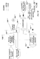
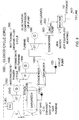
- Figs. 3 and 4 illustrate another system wherein LNG is the motive fluid of an open cycle power plant.
- Fig. 3 is a schematic arrangement of the power system and
- Fig. 4 is a temperature-entropy diagram of the open cycle.
- the power system of an open turbine-based cycle is generally designated as numeral 50.
- LNG 72 e.g. transported by ship to a selected destination, is the motive fluid for power system 50 and circulates through conduits 48.
- Pump 55 delivers cold LNG at state G, the temperature of which is approximately -160°C, to vaporizer 60 at state H.
- Sea water at an average temperature of approximately 5-20°C introduced via line 18 to vaporizer 60 serves to transfer heat to the LNG passing therethrough from state H to state 1.
- the temperature of the LNG consequently rises above its boiling point to a temperature of approximately -10 to 0°C, and the vaporized LNG produced is supplied to turbine 65.
- the sea water is discharged via line 19 from vaporizer 60 is returned to the ocean.
- turbine 65 As the vaporized LNG is expanded in turbine 65 from state I to state J, power or preferably electricity is produced by generator 68 coupled to turbine 65. Preferably, turbine 65 rotates at 1500 RPM or 1800 RPM. Since the LNG at state G has a considerably low temperature of -160°C and is subsequently pressurized by pump 55 from state G to state H so that high pressure vapor is produced in vaporizer 60, the energy in the vaporized LNG is relatively high and is utilized via expansion in turbine 65.
- the temperature of LNG vapor at state J, after expansion within turbine 65, is increased by transferring heat thereto from sea water, which is supplied to, via line 76, and passes through heater 75.
- the temperature of sea water introduced to heater 75 is sufficient to heat the LNG vapor, which may held in storage 82 or, alternatively, be compressed and delivered by compressor 85 through line 83 to a pipeline for distribution of vaporized LNG to end users.
- Compressor 80 which compresses the natural gas prior to transmission may be driven by the power generated by turbine 65 or, if preferred, driven by electricity produced by electric generator 68.
- the pressure of the vaporized natural gas discharged from turbine 65 may be sufficiently high so that the natural gas which is heated in heater 75 can be transmitted through a pipeline without need of a compressor.
- heat such as heat contained in the exhaust gas of a gas turbine may be used to transfer heat to the natural gas in vaporizer 60 or in heater 75 or via a secondary heat transfer fluid.
- a further example designated 10A of a closed cycle power system (similar to the embodiment described with reference to Fig.1 ) is shown, wherein LNG pump 40A is used to pressurize the LNG prior to supplying it to condenser 30A to a pressure, e.g. about 80 bar, for producing a pressure for the re-gasified LNG suitable for supply via line 43 to a pipeline for distribution of vaporized LNG to end users.
- Pump 40A is used rather than compressor in the system shown in Fig. 1 .
- the operation of the present example is similar to the operation of the system described with reference to Figs. 1 and 2 . Consequently, this example is more efficient.
- turbine 25A included in this example preferably rotates at 1500 RPM or 1800 RPM.
- a mixture of propane and ethane or equivalents is the preferred motive fluid for closed organic Rankine power system in this example.
- ethane, ethene or other suitable organic motive fluids can also be used in this example. This is because the cooling curve of the propane/ethane mixture organic motive fluid in the condenser 30A is more suited to the heating curve of LNG at such high pressures enabling the LNG cooling source to be used more effectively (see Fig. 6 ).
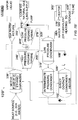
- a dual pressure organic Rankine cycle using a single organic motive fluid e.g.
- ethane, ethene or an equivalent can be used here wherein two different expansion levels and also two condensers can be used (see e.g. Fig. 7 ).
- expanded organic vapors are extracted from turbine 25B in an intermediate stage via line 26B and supplied to condenser 31B wherein organic motive fluid condensate is produced.
- further expanded organic vapors exit turbine 25B via line 27B and are supplied to further condenser 30B wherein further organic motive fluid condensate is produced.
- turbine 25B rotates at 1500 RPM or 1800 RPM.
- Condensate produced in condensers 30B and 31B is supplied to vaporizer 20B using cycle pump II, 16B and cycle pump I, 15B, respectively where sea water (or other equivalent heating) is supplied thereto via line 18B for providing heat to the liquid motive fluid present in vaporizer 20B and producing vaporized motive fluid.
- Condensers 30B and 31B are also supplied with LNG using pump 40B so that the LNG is pressurized to a relatively high pressure e.g. about 80 bars. As can be seen from Fig.
- the LNG is supplied first of all to condenser 30B for condensing the relatively low pressure organic motive fluid vapor exiting turbine 25B and thereafter, the heated LNG exiting condenser 30B is supplied to condenser 31B for condensing the relatively higher pressure organic motive fluid vapor extracted from turbine 25B.
- the supply rate or mass flow of the motive fluid in the bleed cycle, i.e. line 26B, condenser 31B and cycle pump I, 15B can be increased so that additional power can be produced.
- the further heated LNG exiting condenser 31B is preferably supplied to heater 36B for producing LNG vapor which may held in storage 42B or, alternatively, be delivered by through line 43B to a pipeline for distribution of vaporized LNG to end users. While only one turbine is shown in Fig. 7 , if preferred, two separate turbine modules, i.e. a high pressure turbine module and a low pressure turbine module, can be used.
- direct-contact condenser/heater 32B' can be used together with condensers 30B' and 31B'.
- direct-contact condenser/heater 32B' it is ensured that the motive fluid supplied to vaporizer 20B' will not be cold and thus there will be little danger of freezing sea water or heating medium in the vaporizer.
- the mass flow of the motive fluid in the power cycle can be further increased thereby permitting an increase in the power produced.
- the dimensions of the turbine at e.g. its first stage can be improved, e.g. permit the use of blades having a larger size. Consequently, the turbine efficiency is increased.
- production of the motive fluid e.g. ethane, ethane-propane mixture
- the motive fluid e.g. ethane, ethane-propane mixture
- ethane comprising one such fractionate
- the ethane produced can be used for make-up fluid for compensating for loss of motive fluid in the power system.
- an integrated motive fluid supply for the closed cycle organic Rankine cycle power plant is provided.
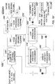
- reheater 22B" is included and used in conjunction with direct-contact condenser/heater 32B" and condensers 30B" and 31B".
- the wetness of the vapors exiting high-pressure turbine module 24B" will be substantially reduced or eliminated thus ensuring that the vapors supplied to low pressure turbine module 25B are substantially dry so that effective expansion and power production can be achieved.
- one heat source can be used for providing heat for the vaporizer while another heat source can be provided for supplying for the reheater.
- a prime mover e.g. a diesel engine or small gas turbine can be provided on e.g. the other side of the LNG pump 40'B".
- low-pressure turbine module 25B By using low-pressure turbine module 25B" to run LNG pump 40'B" directly, no external electrical power is required to operate the pump, providing a more efficient system. Moreover, if preferred, e.g. if varying LNG supply rates are needed, the low-pressure turbine module control can be used such that LNG pump 40'B" can be a variable speed pump. Furthermore, if preferred, electricity produced by generator 28'B” can be used to drive other auxiliaries so that together with the mechanical energy used to drive LNG pump 40'B" the regasification system 10IB" can be made substantially independent from external electricity supply.
- the position of direct contact condenser/heaters 32B' and 32B" can be changed such that the inlet of direct contact condenser/heaters 32B' can receive motive fluid condensate exiting intermediate pressure condenser 31B' (see Fig. 7A ) while direct contact condenser/heaters 32B" can receive pressurized motive fluid condensate exiting cycle pump 16B" (see Fig. 7B ).
- condensate produced in low pressure condenser 30B'" can also be supplied to intermediate pressure condenser 31B'" (intermediate pressure condenser 31B"") to produce condensate from intermediate pressure vapor extracted from an intermediate stage of the turbine by indirect or direct contact respectively.
- Fig. 7D shows a still further alternative version of the system described with reference to Fig. 7 wherein rather than using a direct contact condenser/heater, an indirect condenser/heater is used.
- an indirect condenser/heater is used.
- only one cycle pump can be used wherein suitable valves can be used in the intermediate pressure condensate lines.
- numeral 50A designates an open cycle power plant wherein portion of the LNG is drawn off the main line of the LNG and cycled through a turbine for producing power.
- two direct contact condenser/heaters are used for condensing vapor extracted and exiting the turbine respectively using pressurized LNG pressurized by pump 55A prior to supply to the direct contact condenser/heaters.
- reheater 72B is included and used in conjunction with direct-contact condenser/heaters 31B and 33B.
- the wetness of the vapors exiting high-pressure turbine module 64B will be substantially reduced or eliminated thus ensuring that the vapors supplied to low-pressure turbine module 65B are substantially dry so that effective expansion and power production can be achieved.
- one heat source can be used for providing heat for the vaporizer while another heat source can be provided for supplying for the reheater.
- two indirect contact condensers can be used rather than the direct contact condensers used in the system described with reference to Fig. 7F .
- Two different configurations for the two indirect contact condensers can be used (see Figs. 7H and 7I ).
- an additional direct contact condenser/ heater can be used in addition to the two indirect contact condensers (see Fig. 7J ).
- one direct contact condenser or one indirect contact condenser can be used (see Fig. 7L ).
- an open cycle power plant and closed cycle power plant can be combined (see Fig. 7M ).
- any of the described alternatives can be used as part of the open cycle power plant portion and/or closed cycle power plant portion.
- an alternative used in a closed cycle power plant can be used in an open cycle power plant.
- the alternative described with reference to Fig. 7C closed cycle power plant
- an open cycle power plant e.g. condensers 30B'" and 31B'" can be used in stead of condeners 33B' and 34B' shown in Fig. 7H
- condensers 30B"" and 31B"" can be used in stead of condeners 33B' and 34B' shown in Fig. 7H ).
- pressure levels are described herein, if preferred, several or a number of pressure levels can be used and, if preferred, an equivalent number of condensers can be used to provide effective use of the pressurized LNG as a cold sink or source for the power cycles.
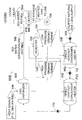
- a further example system is shown wherein a closed organic Rankine cycle power system is used.
- Numeral 10C designates a power plant system including steam turbine system 100 as well closed is used as well as organic Rankine cycle power system 35C.
- LNG pump 40C is preferably used for pressurizing the LNG prior to supplying it to condenser 30C to a pressure, e.g. about 80 bar, for producing a pressure for the regasified LNG suitable for supply via line 43C to a pipeline for distribution of vaporized LNG to end users.
- the preferred organic motive fluid is ethane or equivalent.
- power plant system 10C includes, in addition, gas turbine unit 125 the exhaust gas of which provide the heat source for steam turbine system 100.
- gas turbine unit 125 the exhaust gas of which provide the heat source for steam turbine system 100.
- the exhaust gas of gas turbine 124 is supplied to vaporizer 120 for producing steam from water contained therein.
- the steam produced is supplied to steam turbine 105 where it expands and produces power and preferably drives electric generator 110 generating electricity.
- the expanded steam is supplied to steam condenser/vaporizer 120C where steam condensate is produced and cycle pump 115 supplies the steam condensate to vaporizer 120 thus completing the steam turbine cycle.
- Condenser/vaporizer 120C also acts as a vaporizer and vaporizes liquid organic motive fluid present therein.
- the organic motive fluid vapor produced is supplied to organic vapor turbine 25C and expands therein and produces power and preferably drives electric generator 28C that generates electricity.
- turbine 25C rotates at 1500 RPM or 1800 RPM.
- Expanded organic motive fluid vapor exiting organic vapor turbine is supplied to condenser 30C where organic motive fluid condensate is produced by pressurized LNG supplied thereto by LNG pump 40C.
- Cycle pump 15C supplies the organic motive fluid condensate from condenser 30C to condenser/vaporizer 120C.
- Pressurized LNG is heated in condenser 30C and preferably heater 36C further the pressurized LNG so that re-gasified LNG is produced for storage or supply via a pipeline for distribution of vaporized LNG to end users.
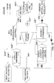
- a closed organic Rankine cycle power system is used.
- Numeral 10D designates a power plant system including intermediate power cycle system 100D as well as closed organic Rankine cycle power system 35D.
- LNG pump 40D is preferably used for pressurizing the LNG prior to supplying it to condenser 30D to a pressure, e.g. about 80 bar, for producing a pressure for the re-gasified LNG suitable for supply via line 43D to a pipeline for distribution of vaporized LNG to end users.
- the preferred organic motive fluid is ethane, ethene or equivalent.
- power plant system 10D includes gas turbine unit 125D the exhaust gas of which provide the heat source for intermediate heat transfer cycle system 100D.
- the exhaust gas of gas turbine 124D is supplied to an intermediate cycle 100D for transferring heat from the exhaust gas to the vaporizer 120D for producing intermediate fluid vapor from intermediate fluid liquid contained therein.
- the vapor produced is supplied to intermediate vapor turbine 105D where it expands and produces power and preferably drives electric generator 110D generating electricity.
- turbine 25D rotates at 1500 RPM or 1800 RPM.
- the expanded vapor is supplied to vapor condenser/vaporizer 120D where intermediate fluid condensate is produced and cycle pump 115D supplies the intermediate fluid condensate to vaporizer 120 thus completing the intermediate fluid turbine cycle.
- Several motive fluids are suitable for use in the intermediate cycle.
- An example of such a motive fluid is pentane, i.e. n-pentane or iso-pentane.
- Condenser/vaporizer 120D also acts as a vaporizer and vaporizes liquid organic motive fluid present therein.
- the organic motive fluid vapor produced is supplied to organic vapor turbine 25D and expands therein and produces power and preferably drives electric generator 28D that generates electricity.
- Expanded organic motive fluid vapor exiting organic vapor turbine is supplied to condenser 30D where organic motive fluid condensate is produced by pressurized LNG supplied thereto by LNG pump 40D.
- Cycle pump 15D supplies the organic motive fluid condensate from condenser 30D to condenser/vaporizer 120D.
- Pressurized LNG is heated in condenser 30D and preferably heater 36D-further the pressurized LNG so that re-gasified LNG is produced for storage or supply via a pipeline for distribution of vaporized LNG to end users. Due to pressurizing of the LNG prior to supplied the LNG to the condenser, it can be advantageous to use a propane/ethane mixture as the organic motive fluid of the organic Rankine cycle power system rather than ethane mentioned above.
- a heat transfer fluid such as thermal oil or other suitable heat transfer fluid can be used for transferring heat from the hot gas to the intermediate fluid and, if preferred, a heat transfer fluid such as an organic, alkylated heat transfer fluid e.g. a synthetic alkylated aromatic heat transfer fluid.
- a heat transfer fluid such as an organic, alkylated heat transfer fluid e.g. a synthetic alkylated aromatic heat transfer fluid. Examples can be an alkyl substituted aromatic fluid, Therminol LT, of the Solutia company having a center in Belgium or a mixture of isomers of an alkylated aromatic fluid, Dowtherm J, of the Dow Chemical Company.
- hydrocarbons having the formula C n H 2n+2 wherein n is between 8 and 20 can also be used for this purpose.
- iso-dodecane or 2,2,4,6, 6-pentamethylheptane iso-eicosane or 2,2,4,4,6,6,8,10, 10-nonamethylundecane, iso-hexadecane or 2,2,4,4,6,8,8-heptamethylnonane, iso-octane or 2, 2, 4 trimethylpentane, iso-nonane or 2,2,4,4 tetramethylpentane and a mixture of two or more of said compounds can be used for such a purpose, in accordance with US patent application serial no.
- an organic, alkylated heat transfer fluid or other hydrocarbon having the formula C n H 2n+2 wherein n is between 8 and 20 is used as the heat transfer fluid, it can be used to also produce power or electricity by e.g. having vapors produced by heat in the hot gas expand in a turbine, with the expanded vapors exiting the turbine being condensed in a condenser which is cooled by intermediate fluid such that intermediate fluid vapor is produced which is supplied to the intermediate vapor turbine.
- a suitable heat transfer fluid such as thermal oil or brine or other suitable heat transfer fluid can be used for transferring heat from the hot gas to the motive fluid, e.g. propane/ethane mixture, ethane, ethene or equivalent used in bottoming organic fluid cycle 35D.
- the preferred rotational speed of the turbine is 1500 or 1800 RPM, if preferred, other speeds can also be used, e.g. 3000 or 3600 RPM.
- a condenser/heater is described and shown, e.g. those described with reference to Figs. 7A (component 32B), 7B (component 32B"), 7B' (component 32B"), 7D, 7E (component 32B"""), 7F (components 33A and 34A), 7G (components 33B and 34B), 7J, 7K (components 33B"" and 34B””), 7M, as a direct condenser/heater, an indirect condenser/heater can also be used.
- motive fluid supplied to the vaporizer in the embodiment or various examples can additionally be heated by motive fluid vapor supplied from the vaporizer in order to pre-heat the motive fluid prior to entering the vaporizer.
- reheater 22B" shown and described with reference to Figs. 7B and 7B " and reheater 72 shown and described with reference to Fig. 7G need not be included.
- an integrated motive fluid supply can be used in all embodiments in which a closed cycle organic Rankine cycle power plant is included. It such be pointed out that, if preferred, propane, being also a fractionate of LNG, can also be distilled out from the LNG in the integrated motive fluid supply so that it can be used together with ethane also so produced, if preferred, to prepare an ethane-propane mixture for use in the closed cycle organic Rankine cycle power plant as its motive fluid.
- the turbine or turbines can be used to run a compressor or pump of the LNG and/or natural gas.
- the methods of the present invention can also be used to cool the inlet air of a gas turbine and/or to carry out intercooling in an intermediate stage or stages of the compressor of a gas turbine. Furthermore, if preferred, the methods of the present invention can be used such that LNG after cooling and condensing the motive fluid can be used to cool the inlet air of a gas turbine and/or used to carry out intercooling in an intermediate stage or stages of the compressor of a gas turbine.
- steam turbine system 100 described with reference to Fig. can be a condensing steam turbine system.
- the heat source for the vaporizer can sea water at a temperature ranging between approximately 5°C to 20°C or heat such as an exhaust gas discharged from a gas turbine or low pressure steam exiting a condensing steam turbine other heat sources may be used.
- heat sources include hot gases from a process, ambient air, exhaust water from a combined cycle steam turbine, hot water from a water heater, etc.
- While methane, ethane, ethene or equivalents are mentioned above as the preferred motive fluids for the organic Rankine cycle power plants they are to be taken as non-limiting examples of the preferred motive fluids.
- other saturated or unsaturated aliphatic hydrocarbons can also be used as the motive fluid for the organic Rankine cycle power plants.
- substituted saturated or unsaturated hydrocarbons can also be used as the motive fluids for the organic Rankine cycle power plants.
- Trifluromethane (CHF 3 ), fluromethane (CH 3 F), tetrafluroethane (C 2 F 4 ) and hexafluroethane (C 2 F 6 ) are also preferred motive fluids for the organic Rankine cycle power plants described herein.
- Chlorine (Cl) substituted saturated or unsaturated hydrocarbons can also be used as the motive fluids for the organic Rankine cycle power plants but would not be used due to their negative environmental impact.
Landscapes
- Engineering & Computer Science (AREA)
- Chemical & Material Sciences (AREA)
- Combustion & Propulsion (AREA)
- Mechanical Engineering (AREA)
- General Engineering & Computer Science (AREA)
- Engine Equipment That Uses Special Cycles (AREA)
- Filling Or Discharging Of Gas Storage Vessels (AREA)
Claims (17)
- Geschlossenes organisches Rankine-Kreislauf-Energie- und Regasifizierungssystem für verflüssigtes Erdgas (LNG), das Folgendes umfasst:a) einen Verdampfer (20), in dem flüssiges Treibfluid verdampft wird, wobei das flüssige Treibfluid ein durch das LNG verflüssigtes Treibfluid ist;b) eine Turbine (25) zum Expandieren des verdampften Treibfluids;c) einen Kondensator (30), dem ein expandierter Treibfluiddampf zugeführt wird, wobei der Kondensator (30) ebenfalls mit LNG versorgt wird, um Wärme von dem expandierten Fluiddampf zu empfangen, wobei das LNG das expandierte Treibfluid kondensiert, das aus der Turbine (25) austritt, wodurch die Temperatur des LNG zunimmt, wenn es durch den Kondensator (30) strömt;d) einen Kondensator/Heizer (36) zum Kondensieren von aus der Turbine extrahierten Dämpfen und zum Erwärmen von Treibfluidkondensat, das dem Kondensator/Heizer von dem Kondensator (30) zugeführt wird;e) eine Leitung, durch die das Treibfluid von dem Auslass des Kondensators (30) zu dem Einlass des Verdampfers (20) strömt; undf) eine Leitung zum Übertragen von regasifiziertem LNG;dadurch gekennzeichnet, dass das System ferner ein integriertes Destillationssystem (46B') umfasst, das mit LNG, das in seine Fraktionen destilliert und fraktioniert wird, versorgt wird, wobei mindestens eine der Fraktionen das Treibfluid des geschlossenen organischen Rankine-Kreislauf-Energiesystems umfasst.
- System nach Anspruch 1, wobei das Treibfluid ein Treibfluid umfasst, das aus der Gruppe ausgewählt wird, die aus Ethan und Methan besteht.
- System nach Anspruch 1, wobei das Treibfluid ein Gemisch aus Propan und Ethan ist.
- System nach Anspruch 1, wobei die Wärmequelle des Verdampfers Meerwasser ist.
- System nach Anspruch 2, wobei die Wärmequelle des Verdampfers aus einer Dampfturbine austretenden Dampf umfasst, wobei die Dampfturbine ein Teil eines kombinierten Kreislaufkraftwerks ist.
- System nach Anspruch 2, das ferner ein Zwischenfluidsystem zum Übertragen von Wärme von der Wärmequelle zu dem Treibfluid umfasst.
- System nach einem der vorhergehenden Ansprüche, das ferner eine Leitung (47B') zum Zuführen mindestens einer der Fraktionen zu dem Verdampfer (20B') umfasst.
- System nach Anspruch 1, das ferner einen weiteren Kondensator (31B, 31B""') zum Kondensieren von expandiertem Dampf umfasst, der aus der Turbine (25B, 25B'"") extrahiert wurde, wobei der weitere Kondensator (31B, 31B'"") durch erwärmtes LNG gekühlt wird, das aus dem Kondensator (30B, 30B""') austritt.
- System nach Anspruch 1, wobei das System ferner Folgendes umfasst: eine weitere Turbine (24B") zum Expandieren von Treibfluiddampf vor dessen Zuführung zu der Turbine (25B") und einen weiteren Kondensator (31B"), dem das expandierte Treibfluid zugeführt wird, das aus der weiteren Turbine (24B") austritt, so dass die weitere Turbine (24B") einen elektrischen Generator (28'B") zur Erzeugung elektrischer Energie antreibt.
- System nach Anspruch 9, wobei der weitere Kondensator (31B") durch erwärmtes LNG gekühlt wird, das aus dem Kondensator austritt.
- System nach Anspruch 1 oder 10, das ferner eine Pumpe (15, 15A, 15B") zum Unterdrucksetzen und Zuführen von flüssigem Treibfluid von dem Kondensator (30, 30A, 32B") zu dem Verdampfer (20, 20A, 20B") umfasst.
- System nach Anspruch 1, das ferner eine Pumpe (40A, 40'B") zum Erhöhen des Drucks des LNG, das dem Kondensator (30A, 30B") zugeführt wird, bevor es dem Kondensator (30A, 30B") zugeführt wird, auf einen Druck umfasst, der dafür geeignet ist, das regasifizierte LNG entlang einer Rohrleitung zu Endverbrauchern zu leiten, wobei die Pumpe (40A, 40'B") von der Turbine (25A, 25B") angetrieben wird und wobei die Pumpe (40'B") zum Erhöhen des Drucks des LNG, das dem Kondensator (30B") zugeführt wird, vor der Zuführung zu dem Kondensator (30B") eine Pumpe mit variabler Geschwindigkeit (40A, 40B") umfasst.
- System nach Anspruch 10, wobei der Kondensator/Heizer (32B") zum Kondensieren von aus der Turbine (24B") extrahierten Dämpfen und zum Erwärmen von Treibfluidkondensat, das dem Kondensator/Heizer (32B") zugeführt wird, einen Direktkontakt-Kondensator/Heizer (32B") zum Kondensieren von aus der weiteren Turbine (24B") austretenden Dämpfen und zum Erwärmen von Treibfluidkondensat, das dem Kondensator/Heizer (32B") zugeführt wird, umfasst.
- System nach Anspruch 13, das ferner eine Leitung zum direkten Verbinden des direkten Kontaktkondensators/Heizers (32B") mit dem Verdampfer (20B") umfasst.
- System nach Anspruch 14, das ferner eine Leitung zum Zuführen von Kondensat aus dem Direktkontakt-Kondensator/Heizer (32B") zu dem weiteren Kondensator (31B") umfasst.
- System nach Anspruch 15, das ferner eine Pumpe (15B") zum Zuführen nur des Kondensats von dem weiteren Kondensator (31B") zu dem Verdampfer (20B") umfasst.
- System nach einem der Ansprüche 1 bis 9, das ferner dadurch gekennzeichnet ist, dass:a) die Turbine ein organisches Hochdruckturbinenmodul (24B") und ein organisches Niederdruckturbinenmodul (25B") umfasst, wobei die Zwischenstufe der Turbine den Ausgang des organischen Hochdruckturbinenmoduls (24B") umfasst, aus dem Dämpfe extrahiert werden, und das organische Niederdruckturbinenmodul (25B") die expandierten Dämpfe, die aus der Hochdruckturbine (24B") austreten, weiter expandiert;b) einen elektrischen Generator (28`B") zur Erzeugung von elektrischer Energie, die von der organischen Hochdruckturbine (24B") betrieben wird;c) wobei der Kondensator einen Zwischendruckkondensator (31B") umfasst, dem expandierter Treibfluiddampf von der Hochdruckturbine (24B") zugeführt wird, wobei der Kondensator (31B") ebenfalls mit LNG versorgt wird, um Wärme von dem expandierten Fluiddampf zu empfangen, wobei das LNG das expandierte Treibfluid kondensiert, das aus der Hochdruckturbine (24B") austritt, wodurch die Temperatur des LNG zunimmt, wenn es durch den Kondensator (31B") strömt;d) einen Niederdruckkondensator (30B") zum Kondensieren von expandiertem Treibfluiddampf, der aus der organischen Niederdruckturbine (25B") austritt, wobei der Niederdruckkondensator (30B") ebenfalls mit LNG versorgt wird, um Wärme von dem expandierten Fluiddampf zu empfangen, der aus der organischen Niederdruckturbine (25B") austritt, wobei das LNG das expandierte Treibfluid kondensiert, das aus der Turbine austritt, wodurch die Temperatur des LNG zunimmt, wenn es durch den Kondensator (30B") strömt;e) eine LNG-Pumpe (40'B"), die von der organischen Niederdruckturbine (25B") betrieben wird, um den Druck des LNG, das dem Niederdruckkondensator (30B") zugeführt wird, bevor es dem Niederdruckkondensator (30B") zugeführt wird, und das danach dem Zwischendruckkondensator (31B") zugeführt wird, auf einen Druck zu erhöhen, der geeignet ist, um das regasifizierte LNG entlang einer Rohrleitung zu Endverbrauchern zu leiten;f) wobei der Kondensator/Heizer (32B") zum Kondensieren von Dämpfen, die aus einer Zwischenstufe der Turbine extrahiert wurden, und zum Erwärmen von Treibfluidkondensat, das dem Kondensator/Heizer (32B") zugeführt wird, einen Direktkontakt-Kondensator/Heizer (32B") zum Kondensieren von Dämpfen, die aus dem Ausgang des organischen Hochdruckturbinenmoduls (24B") extrahiert wurden, und zum Erwärmen von Treibfluidkondensat, das dem Direktkontakt-Kondensator/Heizer (32B") zugeführt wird, umfasst; undg) eine Leitung zum Zuführen von erwärmtem Kondensat, das aus dem Kondensator/Heizer austritt, zu dem Verdampfer (20B").
Applications Claiming Priority (2)
| Application Number | Priority Date | Filing Date | Title |
|---|---|---|---|
| US11/876,450 US7900451B2 (en) | 2007-10-22 | 2007-10-22 | Power and regasification system for LNG |
| PCT/IB2008/002701 WO2009053800A2 (en) | 2007-10-22 | 2008-10-12 | A power and regasification system for lng |
Publications (3)
| Publication Number | Publication Date |
|---|---|
| EP2217847A2 EP2217847A2 (de) | 2010-08-18 |
| EP2217847A4 EP2217847A4 (de) | 2012-02-22 |
| EP2217847B1 true EP2217847B1 (de) | 2018-04-04 |
Family
ID=40562079
Family Applications (1)
| Application Number | Title | Priority Date | Filing Date |
|---|---|---|---|
| EP08841311.7A Active EP2217847B1 (de) | 2007-10-22 | 2008-10-12 | Energie- und regasifizierungsanlage für lng |
Country Status (5)
| Country | Link |
|---|---|
| US (1) | US7900451B2 (de) |
| EP (1) | EP2217847B1 (de) |
| KR (1) | KR101577956B1 (de) |
| IL (1) | IL205179A (de) |
| WO (1) | WO2009053800A2 (de) |
Families Citing this family (34)
| Publication number | Priority date | Publication date | Assignee | Title |
|---|---|---|---|---|
| US9612635B2 (en) | 2012-03-19 | 2017-04-04 | Saudi Arabian Oil Company | Systems and computer programs for simultaneous process and utility systems synthesis in partially and fully decentralized environments |
| US9760099B2 (en) | 2008-06-06 | 2017-09-12 | Saudi Arabian Oil Company | Systems, program code, computer readable media for planning and retrofit of energy efficient eco-industrial parks through inter-time-inter-systems energy integration |
| US9360910B2 (en) * | 2009-10-30 | 2016-06-07 | Saudi Arabian Oil Company | Systems, computer readable media, and computer programs for enhancing energy efficiency via systematic hybrid inter-processes integration |
| FR2945574B1 (fr) * | 2009-05-13 | 2015-10-30 | Inst Francais Du Petrole | Dispositif de controle du fluide de travail circulant dans un circuit ferme fonctionnant selon un cycle de rankine et procede pour un tel dispositif |
| US8237299B2 (en) * | 2009-06-26 | 2012-08-07 | Larry Andrews | Power generation systems, processes for generating energy at an industrial mine site, water heating systems, and processes of heating water |
| NO331474B1 (no) * | 2009-11-13 | 2012-01-09 | Hamworthy Gas Systems As | Installasjon for gjengassing av LNG |
| AT509334B1 (de) * | 2010-07-09 | 2011-08-15 | Lo Solutions Gmbh | Verfahren und vorrichtung zur bereitstellung von elektrischer und thermischer energie, insbesondere in einer hafenanlage |
| FR2976317B1 (fr) * | 2011-06-10 | 2015-03-06 | Elengy | Systeme de production d'electricite utilisant une source froide d'un terminal methanier |
| JP5800295B2 (ja) * | 2011-08-19 | 2015-10-28 | 国立大学法人佐賀大学 | 蒸気動力サイクルシステム |
| US9903232B2 (en) * | 2011-12-22 | 2018-02-27 | Ormat Technologies Inc. | Power and regasification system for LNG |
| DE102012104416A1 (de) * | 2012-03-01 | 2013-09-05 | Institut Für Luft- Und Kältetechnik Gemeinnützige Gmbh | Verfahren und Anordnung zur Speicherung von Energie |
| KR101342800B1 (ko) * | 2012-05-14 | 2013-12-19 | 현대중공업 주식회사 | 액화가스 처리 시스템 및 방법 |
| NO334873B1 (no) * | 2012-11-12 | 2014-06-23 | Rondane Lng As | Modifisert organisk Rankine-syklus (ORC)-prosess |
| KR102049477B1 (ko) * | 2013-06-05 | 2019-11-28 | 한국조선해양 주식회사 | Lng 처리 시스템 |
| KR102053927B1 (ko) * | 2013-06-05 | 2019-12-11 | 한국조선해양 주식회사 | Lng 처리 시스템 |
| FR3015555A1 (fr) | 2013-12-20 | 2015-06-26 | Air Liquide | Procede et appareil de generation d’electricite utilisant une centrale thermique ou nucleaire |
| GB2535005A (en) * | 2015-02-03 | 2016-08-10 | Fluid Energy Solutions Int Ltd | Energy generation systems |
| CN105020578B (zh) * | 2015-07-14 | 2017-07-28 | 河南科技大学 | 一种循环式低温液体气化装置 |
| DE102015012673A1 (de) | 2015-09-30 | 2016-04-07 | Daimler Ag | Vorrichtung zur Abwärmerückgewinnung |
| US10532795B2 (en) | 2016-08-17 | 2020-01-14 | Arcosa Marine Products, Inc. | Flexible regasification and floating thermal energy storage |
| US10718236B2 (en) * | 2016-09-19 | 2020-07-21 | Ormat Technologies, Inc. | Turbine shaft bearing and turbine apparatus |
| IT201700070318A1 (it) * | 2017-06-23 | 2018-12-23 | Exergy Spa | Impianto e processo a ciclo Rankine per la rigassificazione di gas liquefatto |
| KR102023003B1 (ko) * | 2017-10-16 | 2019-11-04 | 두산중공업 주식회사 | 압력차 발전을 이용한 복합 발전 시스템 |
| CN109026235A (zh) * | 2018-06-15 | 2018-12-18 | 沪东中华造船(集团)有限公司 | 一种用于液化天然气浮式存储再气化装置的冷能发电系统 |
| KR102472491B1 (ko) * | 2018-06-27 | 2022-11-30 | 미쯔비시 파워 아메리카스, 아이엔씨. | 복합 사이클 발전소용 유기 랭킨 사이클 |
| FR3099205B1 (fr) | 2019-07-26 | 2022-03-11 | Air Liquide | Procédé de production d’énergie électrique utilisant plusieurs cycles de Rankine combinés |
| FR3099206B1 (fr) | 2019-07-26 | 2022-03-11 | Air Liquide | Procédé de production d’énergie électrique utilisant plusieurs cycles de Rankine combinés |
| KR102074641B1 (ko) | 2019-11-05 | 2020-02-07 | 이상운 | Lng재기화 과정에서의 냉열에너지를 이용한 랭킨 사이클 공정과 화력발전 사이클 공정을 연결한 복합 전기 발전 장치 |
| IT202000018628A1 (it) * | 2020-07-30 | 2022-01-30 | Saipem Spa | Processo per la gassificazione di lng e per la generazione di potenza a bassa temperatura |
| CN112197430A (zh) * | 2020-10-30 | 2021-01-08 | 宁夏凯添燃气发展股份有限公司 | 一种应用于燃气调峰的空气能加热装置 |
| CN112648032B (zh) * | 2020-12-25 | 2022-06-17 | 西安石油大学 | 一种利用lng冷能的bog燃气轮机双级有机朗肯联合循环发电系统 |
| JP2023093169A (ja) * | 2021-12-22 | 2023-07-04 | 三浦工業株式会社 | 船舶用発電システム |
| CN114893268A (zh) * | 2022-05-07 | 2022-08-12 | 杭州制氧机集团股份有限公司 | 一种耦合lng冷能利用换冷设备的发电装置及使用方法 |
| CN118423612A (zh) * | 2024-06-06 | 2024-08-02 | 新疆天业(集团)有限公司 | 一种乙烯生产氯乙烯工艺中液相乙烯连续气化输送工艺及其输送系统 |
Family Cites Families (13)
| Publication number | Priority date | Publication date | Assignee | Title |
|---|---|---|---|---|
| NL7600308A (nl) * | 1975-02-07 | 1976-08-10 | Sulzer Ag | Werkwijze en inrichting voor het verdampen en verwarmen van vloeibaar natuurlijk gas. |
| JPS5491648A (en) * | 1977-12-29 | 1979-07-20 | Toyokichi Nozawa | Lnggfleon generation system |
| JPS5838678B2 (ja) * | 1979-07-17 | 1983-08-24 | 東京電力株式会社 | 液化天然ガスの冷熱回収装置 |
| US4388092A (en) * | 1981-01-27 | 1983-06-14 | Chiyoda Chemical Engineering & Construction | Method for processing LNG for Rankine cycle |
| EP0683847B1 (de) * | 1993-12-10 | 1998-08-12 | Cabot Corporation | Flüssigerdgas befeuertes kombikraftwek |
| US5687570A (en) * | 1994-02-28 | 1997-11-18 | Ormat Industries Ltd. | Externally fired combined cycle gas turbine system |
| US5615561A (en) * | 1994-11-08 | 1997-04-01 | Williams Field Services Company | LNG production in cryogenic natural gas processing plants |
| TW414851B (en) * | 1998-03-27 | 2000-12-11 | Exxon Production Research Co | Producing power from liquefied natural gas |
| US6336316B1 (en) * | 1998-12-21 | 2002-01-08 | Japan Science And Technology Corp. | Heat engine |
| MXPA02000764A (es) * | 1999-07-22 | 2002-07-22 | Bechtel Corp | Un metodo y aparato para vaporizar gas liquido en una planta de energia de ciclo combinado. |
| US6690839B1 (en) * | 2000-01-17 | 2004-02-10 | Tektronix, Inc. | Efficient predictor of subjective video quality rating measures |
| US20030005698A1 (en) * | 2001-05-30 | 2003-01-09 | Conoco Inc. | LNG regassification process and system |
| US7493763B2 (en) * | 2005-04-21 | 2009-02-24 | Ormat Technologies, Inc. | LNG-based power and regasification system |
-
2007
- 2007-10-22 US US11/876,450 patent/US7900451B2/en active Active
-
2008
- 2008-10-12 WO PCT/IB2008/002701 patent/WO2009053800A2/en not_active Ceased
- 2008-10-12 EP EP08841311.7A patent/EP2217847B1/de active Active
- 2008-10-12 KR KR1020107011143A patent/KR101577956B1/ko active Active
-
2010
- 2010-04-18 IL IL205179A patent/IL205179A/en active IP Right Grant
Non-Patent Citations (1)
| Title |
|---|
| None * |
Also Published As
| Publication number | Publication date |
|---|---|
| WO2009053800A4 (en) | 2009-10-22 |
| US20090100845A1 (en) | 2009-04-23 |
| KR20100099132A (ko) | 2010-09-10 |
| WO2009053800A3 (en) | 2009-08-20 |
| WO2009053800A2 (en) | 2009-04-30 |
| EP2217847A2 (de) | 2010-08-18 |
| KR101577956B1 (ko) | 2015-12-16 |
| IL205179A0 (en) | 2010-11-30 |
| IL205179A (en) | 2014-04-30 |
| US7900451B2 (en) | 2011-03-08 |
| EP2217847A4 (de) | 2012-02-22 |
Similar Documents
| Publication | Publication Date | Title |
|---|---|---|
| EP2217847B1 (de) | Energie- und regasifizierungsanlage für lng | |
| CA2605001C (en) | Lng-based power and regasification system | |
| US9903232B2 (en) | Power and regasification system for LNG | |
| KR100191080B1 (ko) | Lng로 부터의 동력 발생 | |
| US20100083670A1 (en) | Method for vaporizing and heating crycogenic fluid | |
| GB2540080A (en) | Cold utilization system, energy system provided with cold utilization system, and method for utilizing cold utilization system | |
| JP2011528094A5 (de) | ||
| EP2027409A1 (de) | Verfahren und anlage zur verdampfung von flüssigerdgas und dessen speicherung | |
| Lee et al. | Thermodynamic assessment of integrated heat recovery system combining exhaust-gas heat and cold energy for LNG regasification process in FSRU vessel | |
| KR20010042204A (ko) | 액화 천연 가스로부터의 동력 생산방법 | |
| EP3947923A1 (de) | Rekomprimierter transkritischer zyklus mit verdampfung in kryogenen oder tieftemperaturanwendungen und/oder mit kühlflüssigkeit | |
| CA2615850C (en) | Configurations and methods for power generation in lng regasification terminals | |
| US20140260253A1 (en) | Thermal energy conversion system for regasification of cryogenic liquids | |
| KR102897566B1 (ko) | 부유식 발전 플랜트 | |
| Iordan et al. | RECOVERY OF LOW-TEMPERATURE WASTE HEAT AND LNG COLD ENERGY. |
Legal Events
| Date | Code | Title | Description |
|---|---|---|---|
| PUAI | Public reference made under article 153(3) epc to a published international application that has entered the european phase |
Free format text: ORIGINAL CODE: 0009012 |
|
| 17P | Request for examination filed |
Effective date: 20100507 |
|
| AK | Designated contracting states |
Kind code of ref document: A2 Designated state(s): AT BE BG CH CY CZ DE DK EE ES FI FR GB GR HR HU IE IS IT LI LT LU LV MC MT NL NO PL PT RO SE SI SK TR |
|
| AX | Request for extension of the european patent |
Extension state: AL BA MK RS |
|
| A4 | Supplementary search report drawn up and despatched |
Effective date: 20120123 |
|
| RIC1 | Information provided on ipc code assigned before grant |
Ipc: F17C 7/04 20060101ALI20120117BHEP Ipc: F01K 25/08 20060101ALI20120117BHEP Ipc: F17C 9/02 20060101AFI20120117BHEP |
|
| DAX | Request for extension of the european patent (deleted) | ||
| RIC1 | Information provided on ipc code assigned before grant |
Ipc: F17C 9/02 20060101AFI20141006BHEP Ipc: F17C 7/04 20060101ALI20141006BHEP Ipc: F01K 25/08 20060101ALI20141006BHEP |
|
| GRAP | Despatch of communication of intention to grant a patent |
Free format text: ORIGINAL CODE: EPIDOSNIGR1 |
|
| INTG | Intention to grant announced |
Effective date: 20141222 |
|
| 17Q | First examination report despatched |
Effective date: 20151218 |
|
| GRAP | Despatch of communication of intention to grant a patent |
Free format text: ORIGINAL CODE: EPIDOSNIGR1 |
|
| GRAJ | Information related to disapproval of communication of intention to grant by the applicant or resumption of examination proceedings by the epo deleted |
Free format text: ORIGINAL CODE: EPIDOSDIGR1 |
|
| GRAP | Despatch of communication of intention to grant a patent |
Free format text: ORIGINAL CODE: EPIDOSNIGR1 |
|
| INTG | Intention to grant announced |
Effective date: 20160704 |
|
| INTC | Intention to grant announced (deleted) | ||
| INTG | Intention to grant announced |
Effective date: 20160719 |
|
| GRAS | Grant fee paid |
Free format text: ORIGINAL CODE: EPIDOSNIGR3 |
|
| STAA | Information on the status of an ep patent application or granted ep patent |
Free format text: STATUS: GRANT OF PATENT IS INTENDED |
|
| GRAJ | Information related to disapproval of communication of intention to grant by the applicant or resumption of examination proceedings by the epo deleted |
Free format text: ORIGINAL CODE: EPIDOSDIGR1 |
|
| GRAL | Information related to payment of fee for publishing/printing deleted |
Free format text: ORIGINAL CODE: EPIDOSDIGR3 |
|
| STAA | Information on the status of an ep patent application or granted ep patent |
Free format text: STATUS: EXAMINATION IS IN PROGRESS |
|
| INTC | Intention to grant announced (deleted) | ||
| GRAP | Despatch of communication of intention to grant a patent |
Free format text: ORIGINAL CODE: EPIDOSNIGR1 |
|
| STAA | Information on the status of an ep patent application or granted ep patent |
Free format text: STATUS: GRANT OF PATENT IS INTENDED |
|
| INTG | Intention to grant announced |
Effective date: 20171107 |
|
| GRAA | (expected) grant |
Free format text: ORIGINAL CODE: 0009210 |
|
| STAA | Information on the status of an ep patent application or granted ep patent |
Free format text: STATUS: THE PATENT HAS BEEN GRANTED |
|
| AK | Designated contracting states |
Kind code of ref document: B1 Designated state(s): AT BE BG CH CY CZ DE DK EE ES FI FR GB GR HR HU IE IS IT LI LT LU LV MC MT NL NO PL PT RO SE SI SK TR |
|
| REG | Reference to a national code |
Ref country code: GB Ref legal event code: FG4D |
|
| REG | Reference to a national code |
Ref country code: CH Ref legal event code: EP |
|
| REG | Reference to a national code |
Ref country code: AT Ref legal event code: REF Ref document number: 985968 Country of ref document: AT Kind code of ref document: T Effective date: 20180415 |
|
| REG | Reference to a national code |
Ref country code: IE Ref legal event code: FG4D |
|
| REG | Reference to a national code |
Ref country code: DE Ref legal event code: R096 Ref document number: 602008054708 Country of ref document: DE |
|
| REG | Reference to a national code |
Ref country code: NL Ref legal event code: MP Effective date: 20180404 |
|
| REG | Reference to a national code |
Ref country code: LT Ref legal event code: MG4D |
|
| PG25 | Lapsed in a contracting state [announced via postgrant information from national office to epo] |
Ref country code: NL Free format text: LAPSE BECAUSE OF FAILURE TO SUBMIT A TRANSLATION OF THE DESCRIPTION OR TO PAY THE FEE WITHIN THE PRESCRIBED TIME-LIMIT Effective date: 20180404 |
|
| PG25 | Lapsed in a contracting state [announced via postgrant information from national office to epo] |
Ref country code: FI Free format text: LAPSE BECAUSE OF FAILURE TO SUBMIT A TRANSLATION OF THE DESCRIPTION OR TO PAY THE FEE WITHIN THE PRESCRIBED TIME-LIMIT Effective date: 20180404 Ref country code: LT Free format text: LAPSE BECAUSE OF FAILURE TO SUBMIT A TRANSLATION OF THE DESCRIPTION OR TO PAY THE FEE WITHIN THE PRESCRIBED TIME-LIMIT Effective date: 20180404 Ref country code: PL Free format text: LAPSE BECAUSE OF FAILURE TO SUBMIT A TRANSLATION OF THE DESCRIPTION OR TO PAY THE FEE WITHIN THE PRESCRIBED TIME-LIMIT Effective date: 20180404 Ref country code: BG Free format text: LAPSE BECAUSE OF FAILURE TO SUBMIT A TRANSLATION OF THE DESCRIPTION OR TO PAY THE FEE WITHIN THE PRESCRIBED TIME-LIMIT Effective date: 20180704 Ref country code: NO Free format text: LAPSE BECAUSE OF FAILURE TO SUBMIT A TRANSLATION OF THE DESCRIPTION OR TO PAY THE FEE WITHIN THE PRESCRIBED TIME-LIMIT Effective date: 20180704 Ref country code: SE Free format text: LAPSE BECAUSE OF FAILURE TO SUBMIT A TRANSLATION OF THE DESCRIPTION OR TO PAY THE FEE WITHIN THE PRESCRIBED TIME-LIMIT Effective date: 20180404 Ref country code: ES Free format text: LAPSE BECAUSE OF FAILURE TO SUBMIT A TRANSLATION OF THE DESCRIPTION OR TO PAY THE FEE WITHIN THE PRESCRIBED TIME-LIMIT Effective date: 20180404 |
|
| PG25 | Lapsed in a contracting state [announced via postgrant information from national office to epo] |
Ref country code: GR Free format text: LAPSE BECAUSE OF FAILURE TO SUBMIT A TRANSLATION OF THE DESCRIPTION OR TO PAY THE FEE WITHIN THE PRESCRIBED TIME-LIMIT Effective date: 20180705 Ref country code: HR Free format text: LAPSE BECAUSE OF FAILURE TO SUBMIT A TRANSLATION OF THE DESCRIPTION OR TO PAY THE FEE WITHIN THE PRESCRIBED TIME-LIMIT Effective date: 20180404 Ref country code: LV Free format text: LAPSE BECAUSE OF FAILURE TO SUBMIT A TRANSLATION OF THE DESCRIPTION OR TO PAY THE FEE WITHIN THE PRESCRIBED TIME-LIMIT Effective date: 20180404 |
|
| REG | Reference to a national code |
Ref country code: AT Ref legal event code: MK05 Ref document number: 985968 Country of ref document: AT Kind code of ref document: T Effective date: 20180404 |
|
| PG25 | Lapsed in a contracting state [announced via postgrant information from national office to epo] |
Ref country code: PT Free format text: LAPSE BECAUSE OF FAILURE TO SUBMIT A TRANSLATION OF THE DESCRIPTION OR TO PAY THE FEE WITHIN THE PRESCRIBED TIME-LIMIT Effective date: 20180806 |
|
| REG | Reference to a national code |
Ref country code: DE Ref legal event code: R097 Ref document number: 602008054708 Country of ref document: DE |
|
| PG25 | Lapsed in a contracting state [announced via postgrant information from national office to epo] |
Ref country code: DK Free format text: LAPSE BECAUSE OF FAILURE TO SUBMIT A TRANSLATION OF THE DESCRIPTION OR TO PAY THE FEE WITHIN THE PRESCRIBED TIME-LIMIT Effective date: 20180404 Ref country code: EE Free format text: LAPSE BECAUSE OF FAILURE TO SUBMIT A TRANSLATION OF THE DESCRIPTION OR TO PAY THE FEE WITHIN THE PRESCRIBED TIME-LIMIT Effective date: 20180404 Ref country code: AT Free format text: LAPSE BECAUSE OF FAILURE TO SUBMIT A TRANSLATION OF THE DESCRIPTION OR TO PAY THE FEE WITHIN THE PRESCRIBED TIME-LIMIT Effective date: 20180404 Ref country code: SK Free format text: LAPSE BECAUSE OF FAILURE TO SUBMIT A TRANSLATION OF THE DESCRIPTION OR TO PAY THE FEE WITHIN THE PRESCRIBED TIME-LIMIT Effective date: 20180404 Ref country code: RO Free format text: LAPSE BECAUSE OF FAILURE TO SUBMIT A TRANSLATION OF THE DESCRIPTION OR TO PAY THE FEE WITHIN THE PRESCRIBED TIME-LIMIT Effective date: 20180404 Ref country code: CZ Free format text: LAPSE BECAUSE OF FAILURE TO SUBMIT A TRANSLATION OF THE DESCRIPTION OR TO PAY THE FEE WITHIN THE PRESCRIBED TIME-LIMIT Effective date: 20180404 |
|
| PLBE | No opposition filed within time limit |
Free format text: ORIGINAL CODE: 0009261 |
|
| STAA | Information on the status of an ep patent application or granted ep patent |
Free format text: STATUS: NO OPPOSITION FILED WITHIN TIME LIMIT |
|
| PG25 | Lapsed in a contracting state [announced via postgrant information from national office to epo] |
Ref country code: IT Free format text: LAPSE BECAUSE OF FAILURE TO SUBMIT A TRANSLATION OF THE DESCRIPTION OR TO PAY THE FEE WITHIN THE PRESCRIBED TIME-LIMIT Effective date: 20180404 |
|
| 26N | No opposition filed |
Effective date: 20190107 |
|
| REG | Reference to a national code |
Ref country code: DE Ref legal event code: R119 Ref document number: 602008054708 Country of ref document: DE |
|
| PG25 | Lapsed in a contracting state [announced via postgrant information from national office to epo] |
Ref country code: SI Free format text: LAPSE BECAUSE OF FAILURE TO SUBMIT A TRANSLATION OF THE DESCRIPTION OR TO PAY THE FEE WITHIN THE PRESCRIBED TIME-LIMIT Effective date: 20180404 |
|
| REG | Reference to a national code |
Ref country code: CH Ref legal event code: PL |
|
| REG | Reference to a national code |
Ref country code: BE Ref legal event code: MM Effective date: 20181031 |
|
| PG25 | Lapsed in a contracting state [announced via postgrant information from national office to epo] |
Ref country code: MC Free format text: LAPSE BECAUSE OF FAILURE TO SUBMIT A TRANSLATION OF THE DESCRIPTION OR TO PAY THE FEE WITHIN THE PRESCRIBED TIME-LIMIT Effective date: 20180404 Ref country code: LU Free format text: LAPSE BECAUSE OF NON-PAYMENT OF DUE FEES Effective date: 20181012 |
|
| REG | Reference to a national code |
Ref country code: IE Ref legal event code: MM4A |
|
| PG25 | Lapsed in a contracting state [announced via postgrant information from national office to epo] |
Ref country code: DE Free format text: LAPSE BECAUSE OF NON-PAYMENT OF DUE FEES Effective date: 20190501 |
|
| PG25 | Lapsed in a contracting state [announced via postgrant information from national office to epo] |
Ref country code: CH Free format text: LAPSE BECAUSE OF NON-PAYMENT OF DUE FEES Effective date: 20181031 Ref country code: FR Free format text: LAPSE BECAUSE OF NON-PAYMENT OF DUE FEES Effective date: 20181031 Ref country code: BE Free format text: LAPSE BECAUSE OF NON-PAYMENT OF DUE FEES Effective date: 20181031 Ref country code: LI Free format text: LAPSE BECAUSE OF NON-PAYMENT OF DUE FEES Effective date: 20181031 |
|
| PG25 | Lapsed in a contracting state [announced via postgrant information from national office to epo] |
Ref country code: IE Free format text: LAPSE BECAUSE OF NON-PAYMENT OF DUE FEES Effective date: 20181012 |
|
| PG25 | Lapsed in a contracting state [announced via postgrant information from national office to epo] |
Ref country code: MT Free format text: LAPSE BECAUSE OF NON-PAYMENT OF DUE FEES Effective date: 20181012 |
|
| PG25 | Lapsed in a contracting state [announced via postgrant information from national office to epo] |
Ref country code: TR Free format text: LAPSE BECAUSE OF FAILURE TO SUBMIT A TRANSLATION OF THE DESCRIPTION OR TO PAY THE FEE WITHIN THE PRESCRIBED TIME-LIMIT Effective date: 20180404 |
|
| PG25 | Lapsed in a contracting state [announced via postgrant information from national office to epo] |
Ref country code: HU Free format text: LAPSE BECAUSE OF FAILURE TO SUBMIT A TRANSLATION OF THE DESCRIPTION OR TO PAY THE FEE WITHIN THE PRESCRIBED TIME-LIMIT; INVALID AB INITIO Effective date: 20081012 Ref country code: CY Free format text: LAPSE BECAUSE OF FAILURE TO SUBMIT A TRANSLATION OF THE DESCRIPTION OR TO PAY THE FEE WITHIN THE PRESCRIBED TIME-LIMIT Effective date: 20180404 |
|
| PG25 | Lapsed in a contracting state [announced via postgrant information from national office to epo] |
Ref country code: IS Free format text: LAPSE BECAUSE OF FAILURE TO SUBMIT A TRANSLATION OF THE DESCRIPTION OR TO PAY THE FEE WITHIN THE PRESCRIBED TIME-LIMIT Effective date: 20180804 |
|
| PGFP | Annual fee paid to national office [announced via postgrant information from national office to epo] |
Ref country code: GB Payment date: 20240829 Year of fee payment: 17 |