EP2217327B1 - Automatische bestimmung eines t-schock-empfänglichen fensters - Google Patents
Automatische bestimmung eines t-schock-empfänglichen fensters Download PDFInfo
- Publication number
- EP2217327B1 EP2217327B1 EP08796614A EP08796614A EP2217327B1 EP 2217327 B1 EP2217327 B1 EP 2217327B1 EP 08796614 A EP08796614 A EP 08796614A EP 08796614 A EP08796614 A EP 08796614A EP 2217327 B1 EP2217327 B1 EP 2217327B1
- Authority
- EP
- European Patent Office
- Prior art keywords
- wave
- shock
- signal
- sensing
- interval
- Prior art date
- Legal status (The legal status is an assumption and is not a legal conclusion. Google has not performed a legal analysis and makes no representation as to the accuracy of the status listed.)
- Active
Links
Images


Classifications
-
- A—HUMAN NECESSITIES
- A61—MEDICAL OR VETERINARY SCIENCE; HYGIENE
- A61N—ELECTROTHERAPY; MAGNETOTHERAPY; RADIATION THERAPY; ULTRASOUND THERAPY
- A61N1/00—Electrotherapy; Circuits therefor
- A61N1/18—Applying electric currents by contact electrodes
- A61N1/32—Applying electric currents by contact electrodes alternating or intermittent currents
- A61N1/38—Applying electric currents by contact electrodes alternating or intermittent currents for producing shock effects
- A61N1/39—Heart defibrillators
- A61N1/3987—Heart defibrillators characterised by the timing or triggering of the shock
-
- A—HUMAN NECESSITIES
- A61—MEDICAL OR VETERINARY SCIENCE; HYGIENE
- A61N—ELECTROTHERAPY; MAGNETOTHERAPY; RADIATION THERAPY; ULTRASOUND THERAPY
- A61N1/00—Electrotherapy; Circuits therefor
- A61N1/18—Applying electric currents by contact electrodes
- A61N1/32—Applying electric currents by contact electrodes alternating or intermittent currents
- A61N1/38—Applying electric currents by contact electrodes alternating or intermittent currents for producing shock effects
- A61N1/385—Devices for inducing an abnormal cardiac function, e.g. fibrillation
-
- A—HUMAN NECESSITIES
- A61—MEDICAL OR VETERINARY SCIENCE; HYGIENE
- A61N—ELECTROTHERAPY; MAGNETOTHERAPY; RADIATION THERAPY; ULTRASOUND THERAPY
- A61N1/00—Electrotherapy; Circuits therefor
- A61N1/18—Applying electric currents by contact electrodes
- A61N1/32—Applying electric currents by contact electrodes alternating or intermittent currents
- A61N1/38—Applying electric currents by contact electrodes alternating or intermittent currents for producing shock effects
- A61N1/39—Heart defibrillators
- A61N1/3925—Monitoring; Protecting
- A61N1/3937—Monitoring output parameters
- A61N1/3943—Monitoring output parameters for threshold determination
-
- A—HUMAN NECESSITIES
- A61—MEDICAL OR VETERINARY SCIENCE; HYGIENE
- A61N—ELECTROTHERAPY; MAGNETOTHERAPY; RADIATION THERAPY; ULTRASOUND THERAPY
- A61N1/00—Electrotherapy; Circuits therefor
- A61N1/18—Applying electric currents by contact electrodes
- A61N1/32—Applying electric currents by contact electrodes alternating or intermittent currents
- A61N1/38—Applying electric currents by contact electrodes alternating or intermittent currents for producing shock effects
- A61N1/39—Heart defibrillators
- A61N1/3956—Implantable devices for applying electric shocks to the heart, e.g. for cardioversion
- A61N1/3962—Implantable devices for applying electric shocks to the heart, e.g. for cardioversion in combination with another heart therapy
- A61N1/39622—Pacing therapy
Definitions
- the invention as set forth in claim 1 relates generally to implantable medical devices and, in particular, to an automated method and apparatus for determining a time interval for delivering T-wave shocks to a patient's heart.
- a shock pulse during the vulnerable period of the cardiac cycle can induce fibrillation, providing the shock energy is greater than a patient-specific minimum value and less than a patient-specific maximum value.
- a shock pulse is generally referred to as a "T-shock” or “T-wave shock” because the time of the vulnerable period during the cardiac cycle generally corresponds to the T-wave of the ECG signal.
- the upper limit of vulnerability (ULV) is the shock strength at or above which fibrillation is not induced when a shock is delivered during the vulnerable period of a normal cardiac cycle.
- the minimum shock strength required to defibrillate the human heart often referred to as the defibrillation threshold (DFT), corresponds quantitatively to the ULV.
- DFT defibrillation threshold
- ICD implantable cardioverter defibrillator
- the ULV which can be measured in regular rhythm, corresponds to a shock strength that defibrillates with a high probability of success.
- T-shock a T-shock delivered to determine the ULV. If a T-shock is properly timed during the vulnerable period, and is greater than or equal to the ULV, fibrillation will not be induced. However, if a T-shock that is below the ULV is delivered just outside the vulnerable period, failure to induce fibrillation may lead to an incorrect determination of the ULV. Correct timing of T-shocks during the vulnerable period can be determined using 12-lead ECG signals by manually measuring the time interval between a test pacing pulse and a selected point on the T-wave. The ICD is then programmed to deliver a shock at that time interval. However, such techniques using 12-lead ECG signals are time-consuming and require considerable skill. A need remains, therefore, for automated methods for determining the correct timing of T-shock delivery for reliable ULV determination and DFT estimation.
- module refers to an application specific integrated circuit (ASIC), an electronic circuit, a processor (shared, dedicated, or group) and memory that execute one or more software or firmware programs, a combinational logic circuit, or other suitable components that provide the described functionality.
- ASIC application specific integrated circuit
- processor shared, dedicated, or group
- memory that execute one or more software or firmware programs, a combinational logic circuit, or other suitable components that provide the described functionality.
- FIG. 1 is a plan view of an ICD coupled to a patient's heart via intracardial leads according to one embodiment of the present invention.
- ICD 10 includes a housing 12 for enclosing circuitry within ICD 10 and a connector block 14 for receiving an electrical connector 18 of high-voltage lead 16 and electrical connector 22 of pacing/sensing lead 20.
- High-voltage lead 16 carries a proximal coil electrode 24 and a distal coil electrode 26.
- High-voltage lead 16 is shown configured to position proximal electrode 24 along the right atrium 28 and/or along the superior vena cava (SVC) and position distal electrode 26 within right ventricle (RV) 30.
- SVC superior vena cava
- RV right ventricle
- Proximal electrode 24 is referred to hereafter as an "SVC coil electrode”, and distal electrode 26 is referred to hereafter as “RV coil electrode”. Alternatively, these two electrodes may be on different leads.
- SVC coil electrode 24, RV coil electrode 26 and the housing 12 of ICD 10 may be used in any combination for delivering a high-voltage shock pulse.
- a shock pulse may be delivered for determining the ULV or DFT at ICD implantation or follow-up or for delivering a defibrillation shock in response to detecting fibrillation.
- Pacing/sensing lead 20 carries two sets of pacing/sensing electrodes, a proximal electrode set 32 positioned within the right atrium 28 and a distal electrode set 34 positioned within the right ventricle 30.
- electrode sets 32 and 34 may be on different leads or on the lead that carries either or both coil electrodes 24 and 26.
- separate electrode pairs may be used for right-ventricular pacing and sensing.
- the leads, electrodes for delivering high-voltage shock pulses and electrodes for pacing and sensing may be intracardiac, epicardial, intravascular, subcutaneous or submuscular designs.
- the ULV is determined after the electrodes and leads have been placed at their intended implant positions. In this manner, the ULV corresponds to the patient and particular arrangement of the electrodes used.
- FIG. 2 is a functional block diagram of one embodiment of a ULV subsystem 50 in electrical connection with a shock subsystem 52.
- ULV subsystem 50 and shock subsystem 52 are component subsystems of ICD 10 of Figure 1 and are enclosed within housing 12 and electrically connected with other ICD circuitry and with ICD leads or electrodes as appropriate to achieve the desired functionality as described herein.
- ULV subsystem 50 includes a test-shock driver 54 for triggering T-wave shocks to be generated by shock subsystem 52.
- a control module 56 in combination with memory unit 64 and timing circuit 58 control test shock driver 54 and pacing circuit 62.
- a sensing, storing, and analyzing circuit 60 is provided for sensing, storing, and analyzing cardiac electrogram (EGM) signals.
- EMM cardiac electrogram
- Shock subsystem 52 is programmable to deliver monophasic or biphasic shocks, having variable tilt, and controllable through a stepwise range of energy outputs from, for example, at least 5 J to at least 30 J.
- shock subsystem 52 is included in a subcutaneous ICD system relying on subcutaneous electrodes for defibrillating the heart, the output range may be substantially higher.
- Shock subsystem 52 is connected to the test shock driver 54, memory 64 and control module 56 of the ULV subsystem 50. Shock subsystem 52 is used to generate test shock pulses used in determining the ULV for a patient as well as generate defibrillation shocks in response to ICD detection of tachycardia or fibrillation.
- ULV measurement techniques described herein are generally performed during cardiac pacing delivered by pacing circuit 62 under the control of timing circuit 58 at a rate slightly higher than an intrinsic heart rate determined by sensing, storing and analyzing circuit 60.
- pacing pulses may be delivered at a predetermined high rate, for example 120 bpm, expected to be above the patient's resting heart rate.
- the pacing circuit 62 is not necessary for embodiments of the invention which are operative during an intrinsic rhythm.
- Control module 56 is set to control the delivery of pacing and shock delivery, providing an initial test-shock energy, and triggering sensing circuit 60 to detect the heart's intrinsic rate and transmit this rate value back to control module 56.
- the starting shock strength is stored in memory unit 64.
- the intrinsic heart rate value is passed to pacing circuit 62.
- Pacing circuit 62 then provides a baseline pacing output to electrode sets 32, 34 that is of a rate sufficient to overdrive the heart's intrinsic rate.
- the sensing, storing, and analyzing circuit 60 then evaluates an EGM signal, which represents the electrical activity of the heart.
- the timing of pacing pulses may be transmitted to the sensing circuit 60 electronically.
- the sensing, storing, and analyzing circuit 60 may identify the pacing pulse during its evaluation of the EGM.
- Sensing, storing and analyzing circuit 60 may be further configured to evaluate EGM signals to detect capture following delivering of a pacing pulse by pacing circuit 62. Successful capture by pacing pulses may be verified by detecting an evoked response following the pacing pulse.
- EGM signals received by sensing, storing and analyzing circuit 60 may include signals sensed using a number of different configurations of implanted electrodes including, but not limited to, intracardiac, transvenous, epicardial, intravascular, subcutaneous, and submuscular leads.
- sensing lead combinations may include leads positioned to record signals from the superior vena cava, the right atrium, the right ventricle, the left ventricle and combinations of electrodes such as between a lead tip electrode and a defibrillation electrode or combinations including pairing leads from the right atrium or the superior vena cava to the right or left ventricles.
- a series of ventricular pacing pulses such as 8-15 pulses, are delivered at an overdrive pacing rate.
- the sensing, storing and analyzing circuit 60 senses the EGM signals following at least some of the pacing pulses and evaluates the T-waves to determine a T-wave center.
- the time interval between the pacing pulse and the T-wave center will be used in setting a test shock time interval for controlling the delivery of a T-wave shock for determining or estimating the patient's ULV.
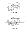
- FIG. 3A is a diagram of a differentially filtered T-wave signal 100 sensed following a pacing pulse 102 illustrating one method for computing a T-wave shock time interval.
- a blanking period 104 is applied following the pacing pulse 102.
- a T-wave sensing window 106 is initiated at the end of the blanking period 104.
- the T-wave signal 100 sensed during the sensing window 106 is analyzed to determine the time interval 110 between the start of the T-wave sensing window to a T-wave center 108, referred to hereafter as the "T-wave center time point" (T CP ).
- T CP T-wave center time point
- the T-wave center time point 108 is computed as the time point corresponding to a center of area of the T-wave.
- the center of the T-wave may be computed from sample points of the digitized T-wave or a time derivative of the T-wave.
- the number of signal sample points N may vary.
- the ventricular pacing pulse 102 is delivered at a pacing interval 112 set at 500ms, the blanking period is set as 280 ms, and the T-wave sensing window 106 is 160 ms, with 40 points sampled during the sensing window 106.
- a T-wave shock interval may be computed using the measured T-wave center time point 110.
- a T-wave shock interval may be computed as the sum of the blanking interval 104 and the interval 110 from the start of the T-wave sensing window 106 to the T-wave center time point 110.
- the T-wave center time point 110 may be computed for multiple T-wave signals and the T-wave shock interval may be computed based on the average, median, maximum, minimum or other function of multiple T-wave center time point measurements.
- a T-shock interval may be computed based on the T-wave center time point and a predetermined offset or a percentage of the computed T-wave center time point interval.
- FIG. 3B is a diagram of a differentially filtered T-wave signal 120 sensed following a pacing pulse 122 illustrating another method for computing a T-wave shock time interval.
- the T-wave center is determined as the center 132 of the differentially filtered T-wave signal width 128.
- the T-wave signal 120 is sampled during T-wave sensing window 126, following a blanking period 124 applied upon delivery of ventricular pacing pulse 122.
- the T-wave width 128 is determined by searching before and after the T-wave signal peak 134 for zero-crossings of the T-wave signal.
- the signal peak 134 may be identified using peak detection methods and may be a positive or negative going peak.
- a T-wave signal width 128 is computed.
- the center 132 of the T-wave width is determined as half the signal width 128.
- the T-wave center time interval 130 is then computed as the interval from the start of the T-wave sensing window 126 to the T-wave width center 132.
- a T-wave shock interval may then be computed using the T CP interval 130, e.g. as the sum of the blanking period 124 and T CP interval 130.
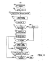
- FIG. 4 is a flow chart of a method for delivering a T-wave shock for use in estimating a patient's defibrillation threshold.
- a T-wave shock interval computed using the methods described herein is useful in any application requiring shock pulse delivery during the vulnerable period, which includes ULV and DFT measurement or estimation.
- Flow chart 200 is intended to illustrate the functional operation of the device, and should not be construed as reflective of a specific form of software or hardware necessary to practice the invention. It is believed that the particular form of software will be determined primarily by the particular system architecture employed in the device and by the particular detection and therapy delivery methodologies employed by the device. Providing software to accomplish the present invention in the context of any modern ICD, given the disclosure herein, is within the abilities of one of skill in the art.
- a "computer-readable medium” includes but is not limited to any volatile or non-volatile media, such as a RAM, ROM, CD-ROM, NVRAM, EEPROM, flash memory, and the like.
- the instructions may be implemented as one or more software modules, which may be executed by themselves or in combination with other software.
- a series of ventricular pacing pulses is delivered at a pacing interval selected to overdrive pace the heart.
- a series of pacing pulses are applied to allow measurement of the ULV during a stable cardiac rhythm.
- a series of pacing pulses may include, for example 6 or more pacing pulses and typically include 8 pacing pulses.
- a blanking period is applied immediately following each pacing pulse at block 204.
- T-wave sensing window is applied at block 206 for sensing the T-wave following each blanking period.
- T-wave signal sensing may be performed using any available sensing electrode configuration. With reference to Figure 1 , T-wave signal sensing may be performed using the RV coil electrode 26 to the combination of the SVC coil electrode 24 and housing 12.
- the sensed T-wave signal is filtered and may undergo additional signal conditioning processes.
- Filtering may include band pass, low pass and differential filtering.
- the EGM signal is band pass filtered at 3 to 100 Hz.
- the T-wave signal is further low pass filtered using a 12 Hz Butterworth filter.
- Signal filtering may include determining a T-wave signal time derivative and using the time derivative for computing a T-wave center.
- differential filtering is performed using a five-point differential filtering method. In various embodiments, different filtering methods may be used for reducing high frequency noise.
- Additional signal condition may include detecting the peak of the filtered T-wave signal and using the peak polarity for correcting signal sample points having the opposite polarity of the peak.
- the peak amplitude polarity (i.e., positive or negative) of the differentially filtered T-wave signal may be used to set all other signal sample points having opposite polarity to zero values. In other words, if the maximum amplitude of the T-wave signal is a positive value, indicating a positive-going T-wave, all negative T-wave signal sample points are reset to zero. If the maximum T-wave amplitude is a negative value, indicating a negative-going T-wave, all positive T-wave signal sample points are set to zero. In this way, noisy sample points having opposite polarity from the T-wave polarity are removed.
- the center of the T-wave with respect to the start time of the T-wave sensing window i.e. the T CP interval
- the T-wave center time point interval may be determined using either of the algorithms described above, i.e., based on the center of the T-wave area or the center of the T-wave width.
- a T-wave center time point interval may be computed using a filtered T-wave signal, using a differential filtered T-wave, or using T-wave signal sample points that have undergone other signal conditioning methods.
- a reliability check may be performed to verify that the T-wave center time points measured for individual T-wave signals are consistent.
- a reliability check may include comparing two or more of the individually measured T-wave center time points.
- the difference between two T-wave center time points may be compared to a reliability threshold. For example, during a series of eight ventricular pacing pulses, the difference between the T-wave center time points measured for the seventh and eighth pacing cycles may be compared to a reliability threshold of 40 ms. If the difference is greater than the reliability threshold, the T-wave center time point is deemed unreliable and may be discarded at block 215.
- the method 200 may be temporarily aborted and repeated at a later time by returning to block 202.
- T-wave center time point measurements may include determining a standard deviation of T CP measurements or performing cross-checks between individual measurements or between individual measurements and an average of all individual measurements.
- the reliability threshold will be defined according to the reliability test methods used.
- different T-wave features, other than T CP may be determined for comparisons of T-wave signals for verifying reliability of the sensed signals.
- the reliability check performed at block 212 may include performing capture verification for ensuring that T-wave measurements are made following pacing pulses that consistently capture the heart.
- a loss of capture during a pacing pulse series can produce anomalous T-wave center point measurements and result in an inappropriate T-wave shock interval.
- Capture verification may be performed by monitoring for an evoked response (QRS complex) during the blanking period following a pacing pulse. Capture verification methods are generally disclosed, for example, in U.S. Pat. No. 6,466,422 (Splett ).
- a T-wave shock interval is computed at block 214 using the measured T-wave center time points.
- the T-wave shock interval may be computed using a percentage, average or median value of one or more T-wave center time point measurements.
- the T-wave shock interval is computed as the blanking period applied following the pacing pulse plus an average of the T-wave center time point interval for the seventh and eight differential filtered T-wave signals measured during a series of eight pacing pulses.
- a stability verification may be performed at block 218 to verify that the cardiac rhythm as remained stable in terms of the T-wave center point since the T-wave shock interval was computed.
- T CP measurements may be repeated on a subset (or all) of the EGM signals sensed following the pacing pulses using the same methods as used at block 210.
- the T CP measurements may be compared to the T CP measurements used for computing the T-shock interval, compared to the computed T-shock interval itself, or used to compute a new T-shock interval that is compared to the T-shock interval computed at block 214. If any of these comparisons result in a stability threshold being exceeded, the method 200 may be aborted at block 215, and repeated either immediately or at a later time by returning to block 202.
- method 200 may store the newly computed T-shock interval and return to block 216 to deliver another series of pacing pulses, without delivering a T-shock.
- the new T-shock interval is stored as the current T-shock interval and another new T-shock interval is computed at block 220 (after verifying stable T CP measurements at block 218.
- a T-wave shock is delivered at block 224 at the stored T-shock interval plus a predetermined offset following the last pacing pulse of the current pacing pulse series.
- multiple T-wave shocks may be delivered using multiple offsets following separate pacing pulse sequences so as to "scan" the T-wave with shock pulses and thereby reduce the likelihood of underestimating the ULV due to an improperly timed T-shock, i.e., outside the vulnerable period.
- An initial offset may be 0 ms such that the T-wave shock is delivered at the computed T-shock interval.
- Subsequent offsets may be negative and/or positive.
- offsets include -20 ms, 0 ms, +20 ms and +40 ms.
- T-shocks may alternatively be delivered on the last pacing pulse of the initial pacing pulse series after computing the T-shock interval at block 214. Furthermore it is recognized that the T-wave center point measurements could be performed during an intrinsic cardiac rhythm.
- the T-wave shock interval is computed relative to a sensed R-wave and T-wave shocks are delivered following a sensed R-wave at the computed T-wave shock (plus any desired offset).
- the results of the T-shock tests may then be used in estimating the patient's defibrillation threshold.
- the T-shocks are delivered at a shock pulse energy that is a safety margin below the maximum ICD output. If fibrillation is not induced, the T-shock energy is considered to be above the patient's ULV, indicating a high probability of successful defibrillation at the tested T-shock energy.
- additional testing may be performed by delivering T-shocks at the computed T-shock interval and predetermined offsets at varying shock energies.
- the T-wave shock may be delivered at each offset from the computed T-shock interval using a shock energy set to a high level thought to be well above the patient's ULV.
- the T-shocks may then be repeated at successively lower energy levels until fibrillation is induced.
- the lowest energy that fails to induce fibrillation is determined as the patient's ULV and can be used in determining if the patient meets ICD implant requirements and in programming a defibrillation shock energy.
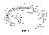
- FIG. 5 is a schematic diagram of an alternative ICD system 300 in which the present invention may be embodied.
- ICD 310 having housing 312 which can be used as a CAN electrode, is coupled via connector block 311 to a right atrial (RA) lead 314, a right ventricular (RV) lead 316, and a left ventricular (LV) lead 318.
- RA lead includes a RA tip electrode 320 and a RA ring electrode 322 for pacing and sensing in the right atrium.
- RV lead 316 includes a RV tip electrode 324 and a RV ring electrode 326 for pacing and sensing in the right ventricle.
- RV lead 316 further includes a RV coil electrode 328 and an SVC coil electrode 330.
- LV lead 318 includes an LV tip electrode 332, an LV ring electrode 334, and an LV coil electrode 336.
- any of electrodes 320 through 336 and housing 312 may be selected for use in sensing T-wave signals for determining a T-wave shock interval.
- a T-wave shock interval may be computed based on a time interval measured with respect to one or more features of sensed T-waves, such as a T-wave center as described above. Multiple sensing electrode configurations may be monitored sequentially or simultaneously for obtaining T-wave signal data for measuring such time intervals.
- the pacing pulses delivered for determining a T-shock interval and prior to delivering a T-shock may be delivered using any available pacing electrodes.
- a series of pacing pulses may be delivered using RV tip and ring electrodes 326 and 328 or using LV tip and ring electrodes 332 and 334.
- T-wave signals obtained using an external ECG leads may also be analyzed for use in computing a T-shock interval.
- ECG signals from a 12-lead ECG monitor 340 may be provided via a hardwired or wireless communication link 342 to an external programmer 350.
- Programmer 350 includes a processor 352 and memory 354 for storing and processing 12-lead ECG signals.
- programmer 350 measures intervals between pacing pulses and T-wave signal peaks.
- a baseline T-wave shock interval is derived from the 12-lead ECG signals based on the occurrence of T-wave signal peaks relative to delivered pacing pulses (or QRS signals).
- This baseline T-wave shock interval may be communicated to ICD 310 via wireless communication link 356 and used by ICD 310 for verifying or adjusting a T-wave shock interval automatically computed by ICD 310.
- the baseline T-wave shock interval may be used in selecting a sensing configuration for timing T-wave shocks delivered by ICD 310 based on the sensing configuration that results in a T-wave shock interval that most closely matches the baseline interval.
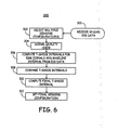
- FIG. 6 is a flow chart of a method 300 for determining a T-wave shock interval using multiple sensing configurations.
- multiple sensing configurations are selected using available implanted electrodes.
- External ECG data may additionally be received as indicated by block 301.
- ECG data may be received by the ICD via a programmer as shown in Figure 5 .
- the programmer may process the 12-lead ECG data and compute a baseline T-wave shock interval based on the 12-lead ECG signals.
- the baseline T-wave shock interval is then be transmitted to the ICD.
- digitized 12-lead ECG data may be transmitted directly to the ICD via a programmer or other wireless communication link and analyzed by the ULV subsystem controller of the ICD for determining a baseline T-wave shock interval.
- a signal quality check may be performed to verify reliable signal quality for the selected sensing configurations. Any signal having an unacceptable frequency content, unacceptable T-wave variability, or unacceptable T-wave center time point measurement differences as compared to other sensing configurations may be rejected for use in determining a final T-wave shock interval.
- the reliability of T-wave center time point measurements for each sensing configuration may be determined. For example, comparisons between T-wave center time point measurements may be made on a beat-by-beat basis for determining the stability of an individual sensed signal. Alternatively, comparisons between single beat measurements and an overall average T-wave center time point measurement may be made to determine if an individual sensing configuration is acceptably stable. For example, beat-by-beat T-wave center time point measurements may be required to be within 15 ms of each other in order to accept the sensing configuration. Alternatively, the sensing electrode configuration resulting in the least variability of T-wave center time point measurements may be selected for use in determining a T-wave shock interval.
- the frequency content of T-wave signals for multiple sensing configurations is evaluated and one or more sensing configurations having the lowest high-frequency signal content are selected for use in determining a final T-shock interval.
- the signal quality check performed at block 304 may include capture verification methods for ensuring that T-wave measurements are made following pacing pulses that consistently capture the heart.
- T-shock intervals are computed for each of the sensing configurations having acceptable signal quality or a single sensing configuration determined to have the best signal quality.
- the T-wave shock interval(s) may be computed using the T-wave center time point methods described above.
- the computed T-wave shock interval(s) for each selected sensing configuration are compared.
- the comparison made at block 308 may include a comparison to a baseline T-wave shock interval derived from the 12-lead ECG data.
- a final T-shock interval is computed at block 310 based on the comparison at block 308.
- a final sensing configuration for timing T-wave shock delivery is then set at block 312 based on the final T-shock interval.
- a final T-wave shock interval to be applied during T-wave shock delivery may be determined as a maximum, minimum, mean, or median T-wave shock interval computed for multiple sensing configurations.
- the final T-wave shock interval is the T-wave shock interval computed for the selected sensing configuration.
- Computation of the final T-wave shock interval may include an adjustment of a computed T-wave shock interval based on the baseline T-wave shock interval derived from external ECG data. For example, a T-wave shock interval computed using T-wave center time point measurements from implanted electrode signals may be adjusted to equal a baseline T-wave shock interval.
- the sensing configuration resulting in a T-wave shock interval that most closely matches the baseline T-wave shock interval may be selected as the final sensing configuration and the corresponding T-wave shock interval used as the final T-wave shock interval.
Landscapes
- Health & Medical Sciences (AREA)
- Cardiology (AREA)
- Radiology & Medical Imaging (AREA)
- Engineering & Computer Science (AREA)
- Biomedical Technology (AREA)
- Nuclear Medicine, Radiotherapy & Molecular Imaging (AREA)
- Life Sciences & Earth Sciences (AREA)
- Animal Behavior & Ethology (AREA)
- General Health & Medical Sciences (AREA)
- Public Health (AREA)
- Veterinary Medicine (AREA)
- Heart & Thoracic Surgery (AREA)
- Electrotherapy Devices (AREA)
- Measurement And Recording Of Electrical Phenomena And Electrical Characteristics Of The Living Body (AREA)
- Measuring Pulse, Heart Rate, Blood Pressure Or Blood Flow (AREA)
Claims (11)
- Medizinisches Vorrichtungssystem mit:einer Stimulationsschaltung (62) zur Abgabe von Stimulationspulsen;Elektroden (24, 26, 32, 34) zur Erfassung eines Herzelektrogramm-(EGM)-Signals, das den Stimulationspulen nachfolgt, und das ein T-Wellensignal aufweist;einer Erfassungsschaltung (60), die mit den Elektroden zur Erfassung des EGM-Signals verbunden ist;einem Steuermodul (56), das mit der Erfassungsschaltung verbunden und dafür eingerichtet ist, die Erfassungsschaltung zu steuern, um das EGM-Signal während eines Erfassungsfensters, das der T-Welle entspricht, zu erfassen, einen T-Wellen-Zeitmittelpunkt zu bestimmen, und ein Test-Schockintervall auf Grundlage des T-WellenZeitmittelpunkts zu bestimmen;einem Speicher (64) zum Speichern des TestSchockintervalls; undeiner Schockerzeugungsschaltung (52, 54) die mit dem Steuermodul verbunden ist, um einen T-Wellen-Schock an ein Herz eines Patienten mit einem T-Wellen-Schockintervall, das dem gespeicherten Test-Schockintervall entspricht, abzugeben,dadurch gekennzeichnet, dass das Steuermodul dafür eingerichtet ist, die Zeit vom Beginn des Erfassungsfensters bis zum Mittelpunkt der Fläche oder Breite der T-Welle als den T-Wellen-Zeitmittelpunkt zu bestimmen.
- System nach Anspruch 1, bei dem das Bestimmen des T-Wellen-Zeitmittelpunkts das Bestimmen einer zeitlichen Ableitung des T-Wellensignals umfasst.
- System nach Anspruch 1, bei dem das Berechnen des Mittelpunkts des T-Wellenbereichs das Berechnen einer gewichteten Summe abgetasteter Punkte des T-Wellensignals umfasst.
- System nach Anspruch 1, bei dem das Berechnen des Mittelpunkts der T-Wellenbreite das Suchen nach einem ersten Nulldurchgang und einem zweiten Nulldurchgang des T-Wellensignals umfasst.
- System nach Anspruch 1, das ferner eine Stimulationsschaltung aufweist, die mit dem Steuermodul und der Erfassungsschaltung verbunden ist;
wobei das Steuermodul dafür eingerichtet ist, die Stimulationsschaltung zu steuern, um eine erste Serie von Stimulationspulsen abzugeben und die Erfassungsschaltung zu steuern, um das EGM-Signal während eines Erfassungsfensters, das der T-Welle entspricht, die jedem der Stimulationspulse nachfolgt, zu erfassen, und ferner dafür eingerichtet ist:ein Merkmal des T-Wellensignals, das nach wenigstens zwei Stimulationspulsen in der ersten Serie von Stimulationspulsen erfasst wurde, zu bestimmen,einen Unterschied zwischen den wenigstens zwei T-Wellensignalmerkmalen zu bestimmen; unddas erste Test-Schockintervall als Antwort darauf zu bestimmen, dass der Unterschied geringer als ein vorbestimmter Schwellwert ist. - System nach Anspruch 5, bei dem das Steuermodul ferner dafür eingerichtet ist, die Stimulationsschaltung zu steuern, um eine zweite Serie von Stimulationspulsen abzugeben,
wobei der T-Wellen-Schock mit dem T-Wellen-Schockintervall abgegeben wird, der dem Test-Schockintervall entspricht, das einem letzten Stimulationspuls der zweiten Serie von Stimulationspulsen nachfolgt,
wobei die Erfassungsschaltung dafür eingerichtet ist, ein T-Wellensignal während der zweiten Serie von Stimulationspulsen zu erfassen; und
das Steuermodul ferner dafür eingerichtet ist, ein Merkmal des T-Wellensignals, das während der zweiten Serie von Stimulationspulsen erfasst wurde, zu bestimmen, und das T-Wellensignalmerkmal, das während der zweiten Serie von
Stimulationspulsen bestimmt wurde, mit dem T-WellenSignalmerkmalen, die während der ersten Serie von Stimulationspulsen bestimmt wurden, zu vergleichen, und entweder eine Abgabe des T-Wellen-Schocks oder ein Abbrechen bzw. Absagen des T-Wellen-Schocks als Antwort auf den Vergleich zwischen dem T-Wellensignalmerkmal, das während der zweiten Serie von Stimulationspulsen erfasst wurde, und den T-Wellensignalmerkmalen, die während der ersten Serie von Stimulationspulsen erfasst wurden, auszuwählen. - System nach Anspruch 6, bei dem das Steuermodul ferner dafür eingerichtet ist, einen T-Wellen-Zeitmittelpunkt während der zweiten Serie zu bestimmen, ein neues Testschock-Intervall als Antwort auf den T-Wellen-Zeitmittelpunkt, der während der zweiten Serie bestimmt wurde, zu bestimmen, das neue Testschock-Intervall, das während der zweiten Serie bestimmt wurde, mit dem gespeicherten Testschock-Intervall das während der ersten Serie bestimmt wurde, zu vergleichen, und das neue Testschock-Intervall als Antwort auf das Abbrechen des T-Wellenschocks zu speichern.
- System nach Anspruch 1, ferner mit:einer Telemetrieschaltung zum Empfangen von externen Elektrokardiogramm-(EKG-)Daten, wobei die Telemetrieschaltung in Kommunikation mit dem Steuermodul steht;einem Prozessor (352), der dafür eingerichtet ist, automatisch ein Grundlinien-T-Wellen-Schockintervall aus dem EKG-Daten zu bestimmen;wobei das Steuermodul dafür eingerichtet ist, das TestSchockintervall, das aus dem EGM-Signal bestimmt wurde, und das Grundlinien-T-Wellen-Schockintervall, das aus dem EKG-Signal bestimmt wurde, zu vergleichen, und das T-Wellen-Schockintervall, das dem Test-Schockintervall entspricht, als Antwort auf den Vergleich zu bestimmen.
- System nach Anspruch 8, bei dem das Erfassen eines Herz-EGM-Signals umfasst:Auswählen einer Anzahl von EGM-Erfassungskonfigurationen;Bestimmen einer Signalqualität für jede aus der Anzahl von Erfassungskonfigurationen; undAuswählen einer Herz-EGM-Erfassungskonfiguration als Antwort auf die Signalqualität;wobei das Bestimmen der Signalqualität das Bestimmen eines Test-Schockintervalls für jede aus der Anzahl von EGM-Erfassungskonfigurationen umfasst und das Auswählen der Herz-EGM-Erfassungskonfiguration das Vergleichen des Testschockintervalls, das für jede aus der Anzahl von EGM-Erfassungskonfigurationen bestimmt wurde, mit dem Grundlinien-T-Wellen-Schockintervall und das Auswählen einer EGM-Erfassungskonfiguration, die einen Testschockintervall entspricht, die am nächsten zu dem Grundlinien-T-Wellen-Schockintervall liegt, umfasst.
- System nach Anspruch 9, bei dem das Bestimmen der Signalqualität das Verifizieren einer Beaufschlagung der Stimulationspulse umfasst.
- Computerlesbares Medium zum Speichern eines Anweisungssatzes, welcher, wenn er in einem medizinischen Vorrichtungssystem nach einem der vorstehenden Ansprüche implementiert ist, das System dazu veranlasst:das Herzelektrogramm (EGM-)Signal, das ein T-Wellensignal aufweist, zu erfassen;den T-Wellen-Zeitmittelpunkt als Antwort auf das Erfassen des EGM-Signals zu bestimmen;das TestschockIntervall als Antwort auf das Bestimmen des T-Wellenzeitmittelpunkts zum Bestimmen; undeinen T-Wellenschock zur Abgabe mit einem T-Wellenschock-Intervall zu planen, der dem Testschockintervall entspricht.
Applications Claiming Priority (2)
| Application Number | Priority Date | Filing Date | Title |
|---|---|---|---|
| US11/866,700 US8064996B2 (en) | 2007-10-03 | 2007-10-03 | Automatic determination of T-shock vulnerable window |
| PCT/US2008/071144 WO2009045610A1 (en) | 2007-10-03 | 2008-09-30 | Automatic determination of t-shock vulnerable window |
Publications (2)
| Publication Number | Publication Date |
|---|---|
| EP2217327A1 EP2217327A1 (de) | 2010-08-18 |
| EP2217327B1 true EP2217327B1 (de) | 2011-08-24 |
Family
ID=39832734
Family Applications (1)
| Application Number | Title | Priority Date | Filing Date |
|---|---|---|---|
| EP08796614A Active EP2217327B1 (de) | 2007-10-03 | 2008-09-30 | Automatische bestimmung eines t-schock-empfänglichen fensters |
Country Status (4)
| Country | Link |
|---|---|
| US (1) | US8064996B2 (de) |
| EP (1) | EP2217327B1 (de) |
| AT (1) | ATE521385T1 (de) |
| WO (1) | WO2009045610A1 (de) |
Families Citing this family (7)
| Publication number | Priority date | Publication date | Assignee | Title |
|---|---|---|---|---|
| US8064996B2 (en) | 2007-10-03 | 2011-11-22 | Medtronic, Inc. | Automatic determination of T-shock vulnerable window |
| US8565865B2 (en) * | 2008-07-24 | 2013-10-22 | Medtronic, Inc. | Methods for the determination of T-shock vulnerable window from far-field electrograms in implantable cardioverter defibrillators |
| US8644923B2 (en) * | 2008-07-24 | 2014-02-04 | Medtronic, Inc. | Determination of upper limit of vulnerability using a variable number of shocks |
| US9956422B2 (en) | 2014-04-24 | 2018-05-01 | Medtronic, Inc. | Therapy delivery methods and circuits for an implantable medical device |
| US10625087B2 (en) | 2014-04-24 | 2020-04-21 | Medtronic, Inc. | Therapy delivery methods and circuits for an implantable medical device |
| US9381370B2 (en) | 2014-09-11 | 2016-07-05 | Medtronic, Inc. | Method and apparatus for determining parameters for oversensing in an implantable medical device |
| US10252068B2 (en) | 2015-11-06 | 2019-04-09 | Medtronic, Inc. | Reducing false positive lead integrity alerts |
Family Cites Families (15)
| Publication number | Priority date | Publication date | Assignee | Title |
|---|---|---|---|---|
| US5105809A (en) | 1990-08-23 | 1992-04-21 | Cardiac Pacemakers, Inc. | System and method for evaluating lead defibrillation requirements of an implanted device without repeated fibrillation induction |
| US5346506A (en) | 1992-11-10 | 1994-09-13 | Mower Morton M | Method for establishing defibrillation threshold for a cardiac defibrillator |
| US5564422A (en) | 1995-04-03 | 1996-10-15 | Chen; Peng-Sheng | Method and apparatus for improved prediction of transvenous defibrillation threshold |
| US5954753A (en) | 1997-06-12 | 1999-09-21 | Sulzer Intermedics, Inc. | Implantable defibrillator with improved testing of capability to defibrillate |
| US6477422B1 (en) | 2000-03-22 | 2002-11-05 | Medtronic, Inc. | Method and apparatus for capture detection |
| US6834204B2 (en) * | 2001-11-05 | 2004-12-21 | Cameron Health, Inc. | Method and apparatus for inducing defibrillation in a patient using a T-shock waveform |
| US7181285B2 (en) | 2000-12-26 | 2007-02-20 | Cardiac Pacemakers, Inc. | Expert system and method |
| CN1193283C (zh) | 2001-01-02 | 2005-03-16 | 深圳赛意法微电子有限公司 | 稳压器和限制稳压器输出电流的方法 |
| US6675042B2 (en) | 2002-04-15 | 2004-01-06 | Charles D. Swerdlow | Defibrillation shock strength determination technology |
| US20040220631A1 (en) | 2003-04-29 | 2004-11-04 | Medtronic, Inc. | Method and apparatus for detecting myocardial electrical recovery and controlling extra-systolic sstimulation |
| US20050038478A1 (en) | 2003-08-11 | 2005-02-17 | Klepfer Ruth N. | Activation recovery interval for classification of cardiac beats in an implanted device |
| US7181275B2 (en) | 2003-12-23 | 2007-02-20 | Medtronic, Inc. | Method and apparatus for actively determining a coupling interval corresponding to a cardiac vulnerable zone |
| US7567835B2 (en) | 2005-04-18 | 2009-07-28 | Medtronic, Inc. | Method and apparatus for identifying oversensing using far-field intracardiac electrograms and marker channels |
| US7634316B2 (en) | 2005-04-28 | 2009-12-15 | Imperception, Inc. | Method and apparatus for validating a pacing train associated with T-shock delivery |
| US8064996B2 (en) | 2007-10-03 | 2011-11-22 | Medtronic, Inc. | Automatic determination of T-shock vulnerable window |
-
2007
- 2007-10-03 US US11/866,700 patent/US8064996B2/en active Active
-
2008
- 2008-09-30 WO PCT/US2008/071144 patent/WO2009045610A1/en not_active Ceased
- 2008-09-30 AT AT08796614T patent/ATE521385T1/de not_active IP Right Cessation
- 2008-09-30 EP EP08796614A patent/EP2217327B1/de active Active
Also Published As
| Publication number | Publication date |
|---|---|
| US20090093860A1 (en) | 2009-04-09 |
| ATE521385T1 (de) | 2011-09-15 |
| US8064996B2 (en) | 2011-11-22 |
| EP2217327A1 (de) | 2010-08-18 |
| WO2009045610A1 (en) | 2009-04-09 |
Similar Documents
| Publication | Publication Date | Title |
|---|---|---|
| US12042651B2 (en) | Systems and methods for automated capture threshold testing and associated his bundle pacing | |
| EP1578490B1 (de) | System zur automatischen auswahl des evozierten reaktionsvektors mit hilfe einer wellenformanalyse der evozierten reaktion | |
| CN107530021B (zh) | 具有用于判定是否满足可电击节律分类标准包括判定t波过度感测的装置的可植入医疗设备 | |
| EP1615693B1 (de) | Vorrichtung zur identifizierung von kardialem und nicht-kardialem oversensing durch messung von intrakardialen elektrogrammen | |
| US5531767A (en) | Method and apparatus for delivering defibrillation shocks with improved effectiveness | |
| US6731985B2 (en) | Implantable cardiac stimulation system and method for automatic capture verification calibration | |
| US20080033494A1 (en) | Shock timing technology | |
| EP2217327B1 (de) | Automatische bestimmung eines t-schock-empfänglichen fensters | |
| US9561005B2 (en) | Method and apparatus for beat acquisition during template generation in a medical device having dual sensing vectors | |
| WO1998025672A1 (en) | Implantable cardiac stimulator with capture detection and impedance based autotuning of capture detection | |
| WO2008134422A2 (en) | Method and apparatus for subcutaneous ecg vector acceptability and selection | |
| EP3247266A1 (de) | Verfahren und vorrichtung zur herzschlagerfassung während der vorlagenerzeugung in einer medizinischen vorrichtung mit doppelten messsensoren | |
| EP2328654B1 (de) | Bestimmung der obergrenze der anfälligkeit mit einer variablen anzahl von stössen | |
| EP2654888B1 (de) | Rateninitialisierung und overdrive-schrittsteuerung zur prüfung der erfassungsschwelle | |
| EP1899008B1 (de) | Gerät zur validierung eines pacing-trains im zusammenhang mit t-schock-verabreichung | |
| EP2346569B1 (de) | Verfahren zur bestimmung des t-shock-empfindlichen fensters in weitfeld-elektrogrammen in implantierbaren kardioverter-defibrillatoren | |
| US8831722B2 (en) | Shock timing technology | |
| EP2529788A1 (de) | Bestimmung der Therapieeinstellungen zur Herzneusynchronisierung | |
| EP0561491A2 (de) | Kardiovertierer/Defibrillator mit Off-Line-EKG-Analyse | |
| EP3247455B1 (de) | Verfahren und vorrichtung zur herzschlagerfassung während der vorlagenerzeugung in einer medizinischen vorrichtung mit doppelten messsensoren |
Legal Events
| Date | Code | Title | Description |
|---|---|---|---|
| PUAI | Public reference made under article 153(3) epc to a published international application that has entered the european phase |
Free format text: ORIGINAL CODE: 0009012 |
|
| 17P | Request for examination filed |
Effective date: 20100503 |
|
| AK | Designated contracting states |
Kind code of ref document: A1 Designated state(s): AT BE BG CH CY CZ DE DK EE ES FI FR GB GR HR HU IE IS IT LI LT LU LV MC MT NL NO PL PT RO SE SI SK TR |
|
| AX | Request for extension of the european patent |
Extension state: AL BA MK RS |
|
| DAX | Request for extension of the european patent (deleted) | ||
| GRAP | Despatch of communication of intention to grant a patent |
Free format text: ORIGINAL CODE: EPIDOSNIGR1 |
|
| GRAS | Grant fee paid |
Free format text: ORIGINAL CODE: EPIDOSNIGR3 |
|
| GRAA | (expected) grant |
Free format text: ORIGINAL CODE: 0009210 |
|
| AK | Designated contracting states |
Kind code of ref document: B1 Designated state(s): AT BE BG CH CY CZ DE DK EE ES FI FR GB GR HR HU IE IS IT LI LT LU LV MC MT NL NO PL PT RO SE SI SK TR |
|
| REG | Reference to a national code |
Ref country code: GB Ref legal event code: FG4D |
|
| REG | Reference to a national code |
Ref country code: CH Ref legal event code: EP |
|
| REG | Reference to a national code |
Ref country code: IE Ref legal event code: FG4D |
|
| REG | Reference to a national code |
Ref country code: DE Ref legal event code: R096 Ref document number: 602008009147 Country of ref document: DE Effective date: 20111020 |
|
| REG | Reference to a national code |
Ref country code: NL Ref legal event code: VDEP Effective date: 20110824 |
|
| LTIE | Lt: invalidation of european patent or patent extension |
Effective date: 20110824 |
|
| PG25 | Lapsed in a contracting state [announced via postgrant information from national office to epo] |
Ref country code: SE Free format text: LAPSE BECAUSE OF FAILURE TO SUBMIT A TRANSLATION OF THE DESCRIPTION OR TO PAY THE FEE WITHIN THE PRESCRIBED TIME-LIMIT Effective date: 20110824 Ref country code: NL Free format text: LAPSE BECAUSE OF FAILURE TO SUBMIT A TRANSLATION OF THE DESCRIPTION OR TO PAY THE FEE WITHIN THE PRESCRIBED TIME-LIMIT Effective date: 20110824 Ref country code: HR Free format text: LAPSE BECAUSE OF FAILURE TO SUBMIT A TRANSLATION OF THE DESCRIPTION OR TO PAY THE FEE WITHIN THE PRESCRIBED TIME-LIMIT Effective date: 20110824 Ref country code: IS Free format text: LAPSE BECAUSE OF FAILURE TO SUBMIT A TRANSLATION OF THE DESCRIPTION OR TO PAY THE FEE WITHIN THE PRESCRIBED TIME-LIMIT Effective date: 20111224 Ref country code: LT Free format text: LAPSE BECAUSE OF FAILURE TO SUBMIT A TRANSLATION OF THE DESCRIPTION OR TO PAY THE FEE WITHIN THE PRESCRIBED TIME-LIMIT Effective date: 20110824 Ref country code: PT Free format text: LAPSE BECAUSE OF FAILURE TO SUBMIT A TRANSLATION OF THE DESCRIPTION OR TO PAY THE FEE WITHIN THE PRESCRIBED TIME-LIMIT Effective date: 20111226 Ref country code: FI Free format text: LAPSE BECAUSE OF FAILURE TO SUBMIT A TRANSLATION OF THE DESCRIPTION OR TO PAY THE FEE WITHIN THE PRESCRIBED TIME-LIMIT Effective date: 20110824 Ref country code: NO Free format text: LAPSE BECAUSE OF FAILURE TO SUBMIT A TRANSLATION OF THE DESCRIPTION OR TO PAY THE FEE WITHIN THE PRESCRIBED TIME-LIMIT Effective date: 20111124 |
|
| REG | Reference to a national code |
Ref country code: AT Ref legal event code: MK05 Ref document number: 521385 Country of ref document: AT Kind code of ref document: T Effective date: 20110824 |
|
| PG25 | Lapsed in a contracting state [announced via postgrant information from national office to epo] |
Ref country code: SI Free format text: LAPSE BECAUSE OF FAILURE TO SUBMIT A TRANSLATION OF THE DESCRIPTION OR TO PAY THE FEE WITHIN THE PRESCRIBED TIME-LIMIT Effective date: 20110824 Ref country code: PL Free format text: LAPSE BECAUSE OF FAILURE TO SUBMIT A TRANSLATION OF THE DESCRIPTION OR TO PAY THE FEE WITHIN THE PRESCRIBED TIME-LIMIT Effective date: 20110824 Ref country code: CY Free format text: LAPSE BECAUSE OF FAILURE TO SUBMIT A TRANSLATION OF THE DESCRIPTION OR TO PAY THE FEE WITHIN THE PRESCRIBED TIME-LIMIT Effective date: 20110824 Ref country code: GR Free format text: LAPSE BECAUSE OF FAILURE TO SUBMIT A TRANSLATION OF THE DESCRIPTION OR TO PAY THE FEE WITHIN THE PRESCRIBED TIME-LIMIT Effective date: 20111125 Ref country code: AT Free format text: LAPSE BECAUSE OF FAILURE TO SUBMIT A TRANSLATION OF THE DESCRIPTION OR TO PAY THE FEE WITHIN THE PRESCRIBED TIME-LIMIT Effective date: 20110824 Ref country code: LV Free format text: LAPSE BECAUSE OF FAILURE TO SUBMIT A TRANSLATION OF THE DESCRIPTION OR TO PAY THE FEE WITHIN THE PRESCRIBED TIME-LIMIT Effective date: 20110824 |
|
| PG25 | Lapsed in a contracting state [announced via postgrant information from national office to epo] |
Ref country code: BE Free format text: LAPSE BECAUSE OF FAILURE TO SUBMIT A TRANSLATION OF THE DESCRIPTION OR TO PAY THE FEE WITHIN THE PRESCRIBED TIME-LIMIT Effective date: 20110824 |
|
| PG25 | Lapsed in a contracting state [announced via postgrant information from national office to epo] |
Ref country code: CZ Free format text: LAPSE BECAUSE OF FAILURE TO SUBMIT A TRANSLATION OF THE DESCRIPTION OR TO PAY THE FEE WITHIN THE PRESCRIBED TIME-LIMIT Effective date: 20110824 Ref country code: SK Free format text: LAPSE BECAUSE OF FAILURE TO SUBMIT A TRANSLATION OF THE DESCRIPTION OR TO PAY THE FEE WITHIN THE PRESCRIBED TIME-LIMIT Effective date: 20110824 Ref country code: MC Free format text: LAPSE BECAUSE OF NON-PAYMENT OF DUE FEES Effective date: 20110930 |
|
| PG25 | Lapsed in a contracting state [announced via postgrant information from national office to epo] |
Ref country code: RO Free format text: LAPSE BECAUSE OF FAILURE TO SUBMIT A TRANSLATION OF THE DESCRIPTION OR TO PAY THE FEE WITHIN THE PRESCRIBED TIME-LIMIT Effective date: 20110824 Ref country code: IT Free format text: LAPSE BECAUSE OF FAILURE TO SUBMIT A TRANSLATION OF THE DESCRIPTION OR TO PAY THE FEE WITHIN THE PRESCRIBED TIME-LIMIT Effective date: 20110824 Ref country code: EE Free format text: LAPSE BECAUSE OF FAILURE TO SUBMIT A TRANSLATION OF THE DESCRIPTION OR TO PAY THE FEE WITHIN THE PRESCRIBED TIME-LIMIT Effective date: 20110824 |
|
| PG25 | Lapsed in a contracting state [announced via postgrant information from national office to epo] |
Ref country code: DK Free format text: LAPSE BECAUSE OF FAILURE TO SUBMIT A TRANSLATION OF THE DESCRIPTION OR TO PAY THE FEE WITHIN THE PRESCRIBED TIME-LIMIT Effective date: 20110824 |
|
| PLBE | No opposition filed within time limit |
Free format text: ORIGINAL CODE: 0009261 |
|
| STAA | Information on the status of an ep patent application or granted ep patent |
Free format text: STATUS: NO OPPOSITION FILED WITHIN TIME LIMIT |
|
| REG | Reference to a national code |
Ref country code: IE Ref legal event code: MM4A |
|
| PG25 | Lapsed in a contracting state [announced via postgrant information from national office to epo] |
Ref country code: IE Free format text: LAPSE BECAUSE OF NON-PAYMENT OF DUE FEES Effective date: 20110930 |
|
| 26N | No opposition filed |
Effective date: 20120525 |
|
| REG | Reference to a national code |
Ref country code: DE Ref legal event code: R097 Ref document number: 602008009147 Country of ref document: DE Effective date: 20120525 |
|
| PG25 | Lapsed in a contracting state [announced via postgrant information from national office to epo] |
Ref country code: MT Free format text: LAPSE BECAUSE OF FAILURE TO SUBMIT A TRANSLATION OF THE DESCRIPTION OR TO PAY THE FEE WITHIN THE PRESCRIBED TIME-LIMIT Effective date: 20110824 |
|
| PG25 | Lapsed in a contracting state [announced via postgrant information from national office to epo] |
Ref country code: ES Free format text: LAPSE BECAUSE OF FAILURE TO SUBMIT A TRANSLATION OF THE DESCRIPTION OR TO PAY THE FEE WITHIN THE PRESCRIBED TIME-LIMIT Effective date: 20111205 |
|
| REG | Reference to a national code |
Ref country code: CH Ref legal event code: PL |
|
| GBPC | Gb: european patent ceased through non-payment of renewal fee |
Effective date: 20120930 |
|
| PG25 | Lapsed in a contracting state [announced via postgrant information from national office to epo] |
Ref country code: LU Free format text: LAPSE BECAUSE OF NON-PAYMENT OF DUE FEES Effective date: 20110930 |
|
| PG25 | Lapsed in a contracting state [announced via postgrant information from national office to epo] |
Ref country code: BG Free format text: LAPSE BECAUSE OF FAILURE TO SUBMIT A TRANSLATION OF THE DESCRIPTION OR TO PAY THE FEE WITHIN THE PRESCRIBED TIME-LIMIT Effective date: 20111124 |
|
| PG25 | Lapsed in a contracting state [announced via postgrant information from national office to epo] |
Ref country code: LI Free format text: LAPSE BECAUSE OF NON-PAYMENT OF DUE FEES Effective date: 20120930 Ref country code: CH Free format text: LAPSE BECAUSE OF NON-PAYMENT OF DUE FEES Effective date: 20120930 Ref country code: GB Free format text: LAPSE BECAUSE OF NON-PAYMENT OF DUE FEES Effective date: 20120930 |
|
| PG25 | Lapsed in a contracting state [announced via postgrant information from national office to epo] |
Ref country code: TR Free format text: LAPSE BECAUSE OF FAILURE TO SUBMIT A TRANSLATION OF THE DESCRIPTION OR TO PAY THE FEE WITHIN THE PRESCRIBED TIME-LIMIT Effective date: 20110824 |
|
| PG25 | Lapsed in a contracting state [announced via postgrant information from national office to epo] |
Ref country code: HU Free format text: LAPSE BECAUSE OF FAILURE TO SUBMIT A TRANSLATION OF THE DESCRIPTION OR TO PAY THE FEE WITHIN THE PRESCRIBED TIME-LIMIT Effective date: 20110824 |
|
| REG | Reference to a national code |
Ref country code: FR Ref legal event code: PLFP Year of fee payment: 9 |
|
| REG | Reference to a national code |
Ref country code: FR Ref legal event code: PLFP Year of fee payment: 10 |
|
| REG | Reference to a national code |
Ref country code: FR Ref legal event code: PLFP Year of fee payment: 11 |
|
| PGFP | Annual fee paid to national office [announced via postgrant information from national office to epo] |
Ref country code: DE Payment date: 20250820 Year of fee payment: 18 |
|
| PGFP | Annual fee paid to national office [announced via postgrant information from national office to epo] |
Ref country code: FR Payment date: 20250821 Year of fee payment: 18 |