EP2217322B1 - Vorrichtung zur stimulierung von lebendem gewebe durch mikroelektroden und entfernbares modul und seine verwendung - Google Patents
Vorrichtung zur stimulierung von lebendem gewebe durch mikroelektroden und entfernbares modul und seine verwendung Download PDFInfo
- Publication number
- EP2217322B1 EP2217322B1 EP08842542.6A EP08842542A EP2217322B1 EP 2217322 B1 EP2217322 B1 EP 2217322B1 EP 08842542 A EP08842542 A EP 08842542A EP 2217322 B1 EP2217322 B1 EP 2217322B1
- Authority
- EP
- European Patent Office
- Prior art keywords
- microelectrodes
- supplemental
- stimulation
- conductive surface
- living tissue
- Prior art date
- Legal status (The legal status is an assumption and is not a legal conclusion. Google has not performed a legal analysis and makes no representation as to the accuracy of the status listed.)
- Active
Links
Images




Classifications
-
- A—HUMAN NECESSITIES
- A61—MEDICAL OR VETERINARY SCIENCE; HYGIENE
- A61N—ELECTROTHERAPY; MAGNETOTHERAPY; RADIATION THERAPY; ULTRASOUND THERAPY
- A61N1/00—Electrotherapy; Circuits therefor
- A61N1/18—Applying electric currents by contact electrodes
- A61N1/32—Applying electric currents by contact electrodes alternating or intermittent currents
- A61N1/36—Applying electric currents by contact electrodes alternating or intermittent currents for stimulation
- A61N1/3605—Implantable neurostimulators for stimulating central or peripheral nerve system
- A61N1/36128—Control systems
- A61N1/36146—Control systems specified by the stimulation parameters
- A61N1/36182—Direction of the electrical field, e.g. with sleeve around stimulating electrode
- A61N1/36185—Selection of the electrode configuration
-
- A—HUMAN NECESSITIES
- A61—MEDICAL OR VETERINARY SCIENCE; HYGIENE
- A61B—DIAGNOSIS; SURGERY; IDENTIFICATION
- A61B5/00—Measuring for diagnostic purposes; Identification of persons
- A61B5/24—Detecting, measuring or recording bioelectric or biomagnetic signals of the body or parts thereof
-
- A—HUMAN NECESSITIES
- A61—MEDICAL OR VETERINARY SCIENCE; HYGIENE
- A61N—ELECTROTHERAPY; MAGNETOTHERAPY; RADIATION THERAPY; ULTRASOUND THERAPY
- A61N1/00—Electrotherapy; Circuits therefor
- A61N1/02—Details
- A61N1/04—Electrodes
- A61N1/05—Electrodes for implantation or insertion into the body, e.g. heart electrode
-
- A—HUMAN NECESSITIES
- A61—MEDICAL OR VETERINARY SCIENCE; HYGIENE
- A61N—ELECTROTHERAPY; MAGNETOTHERAPY; RADIATION THERAPY; ULTRASOUND THERAPY
- A61N1/00—Electrotherapy; Circuits therefor
- A61N1/18—Applying electric currents by contact electrodes
- A61N1/32—Applying electric currents by contact electrodes alternating or intermittent currents
- A61N1/36—Applying electric currents by contact electrodes alternating or intermittent currents for stimulation
- A61N1/3605—Implantable neurostimulators for stimulating central or peripheral nerve system
- A61N1/3606—Implantable neurostimulators for stimulating central or peripheral nerve system adapted for a particular treatment
- A61N1/36071—Pain
-
- A—HUMAN NECESSITIES
- A61—MEDICAL OR VETERINARY SCIENCE; HYGIENE
- A61B—DIAGNOSIS; SURGERY; IDENTIFICATION
- A61B2562/00—Details of sensors; Constructional details of sensor housings or probes; Accessories for sensors
- A61B2562/04—Arrangements of multiple sensors of the same type
- A61B2562/046—Arrangements of multiple sensors of the same type in a matrix array
-
- A—HUMAN NECESSITIES
- A61—MEDICAL OR VETERINARY SCIENCE; HYGIENE
- A61N—ELECTROTHERAPY; MAGNETOTHERAPY; RADIATION THERAPY; ULTRASOUND THERAPY
- A61N1/00—Electrotherapy; Circuits therefor
- A61N1/02—Details
- A61N1/04—Electrodes
- A61N1/05—Electrodes for implantation or insertion into the body, e.g. heart electrode
- A61N1/0526—Head electrodes
- A61N1/0541—Cochlear electrodes
-
- A—HUMAN NECESSITIES
- A61—MEDICAL OR VETERINARY SCIENCE; HYGIENE
- A61N—ELECTROTHERAPY; MAGNETOTHERAPY; RADIATION THERAPY; ULTRASOUND THERAPY
- A61N1/00—Electrotherapy; Circuits therefor
- A61N1/02—Details
- A61N1/04—Electrodes
- A61N1/05—Electrodes for implantation or insertion into the body, e.g. heart electrode
- A61N1/0526—Head electrodes
- A61N1/0543—Retinal electrodes
-
- A—HUMAN NECESSITIES
- A61—MEDICAL OR VETERINARY SCIENCE; HYGIENE
- A61N—ELECTROTHERAPY; MAGNETOTHERAPY; RADIATION THERAPY; ULTRASOUND THERAPY
- A61N1/00—Electrotherapy; Circuits therefor
- A61N1/02—Details
- A61N1/04—Electrodes
- A61N1/05—Electrodes for implantation or insertion into the body, e.g. heart electrode
- A61N1/0551—Spinal or peripheral nerve electrodes
-
- A—HUMAN NECESSITIES
- A61—MEDICAL OR VETERINARY SCIENCE; HYGIENE
- A61N—ELECTROTHERAPY; MAGNETOTHERAPY; RADIATION THERAPY; ULTRASOUND THERAPY
- A61N1/00—Electrotherapy; Circuits therefor
- A61N1/18—Applying electric currents by contact electrodes
- A61N1/32—Applying electric currents by contact electrodes alternating or intermittent currents
- A61N1/36—Applying electric currents by contact electrodes alternating or intermittent currents for stimulation
- A61N1/36014—External stimulators, e.g. with patch electrodes
- A61N1/36017—External stimulators, e.g. with patch electrodes with leads or electrodes penetrating the skin
Definitions
- the invention relates to a device for stimulating living tissue with a microelectrode matrix.
- Microelectrode matrices are used for example in neurophysiological and pharmacological applications.
- These matrices are used to record the electrical activities of a living tissue (cellular or multicellular activities). They are also used to electrically stimulate a tissue. This applies for any type of excitable tissue, including nervous tissue, muscle tissue, for example cardiac, or stem cells.
- a term application concerns neuroprostheses, and aims to develop microstimulators implanted in the body (in particular human, but also in animals) to generate electrical stimulations, in order to compensate for malfunctions of neural networks in the case of a disease or abnormality of an organ.
- microstimulators implanted in the body (in particular human, but also in animals) to generate electrical stimulations, in order to compensate for malfunctions of neural networks in the case of a disease or abnormality of an organ.
- These are, for example, deep brain stimulations in the case of neurodegenerative diseases (for example Parkinson's, Alzheimer's, dementia), the spinal cord in the case of motor disorders or treatment of pain, for example, muscles, or still sensory structures such as the peripheral nerves, the retina, the cochlea (inner ear), or other sensory relays.
- the microelectrode matrix In order to be able to stimulate living neurons, the microelectrode matrix must therefore be dimensioned at the level of the living tissue to be stimulated.
- the stimulation microelectrodes usually have a diameter of the order of a few tens of micrometers or less and a spacing of a few hundred micrometers or less. However, for more macroscopic stimulation of the central or peripheral nervous system, larger electrodes (of the order of mm or cm) are used.
- the documents [1] to [6] mentioned below describe pacing electrode matrices, as well as methods for using them.
- the matrix may comprise several tens or hundreds of stimulation microelectrodes.
- the document [1] thus provides a matrix having 36 stimulation microelectrodes and 4 reference electrodes.
- the document [5] provides that the microelectrodes are divided into two groups, one used for stimulation and the other used for recording, which doubles the number of microelectrodes.
- microelectrode stimulation matrix if a stimulation signal is sent to one of the microelectrodes, it is to stimulate the zone of the nervous tissue located opposite this microelectrode.
- Monopolar stimulations are thus known, in which the stimulation of a living cell VIV is carried out between a stimulation microelectrode 11 among the stimulation microelectrodes 10 of the matrix 1 and a remote mass MD of the stimulation microelectrode matrix 1, as this is represented at the figure 1 .
- stimulation is performed between two stimulation microelectrodes 11 & 12 of the matrix 1.
- WO 2005/087309 discloses an arrangement of electrodes for excitement of nerves or muscles which consists of replacing large electrodes with a group of smaller electrodes occupying a total size comparable to that of the large electrode. These groups form a unique stimulation site.
- Each stimulation site comprises three or five groups each consisting of electrically conductive surface elements which are interconnected by conductive tracks.
- An array of electrodes comprises seven stimulation sites each having five groups each consisting of electrically conductive surface elements which are interconnected by conductive tracks.
- the use of electrode groups for each stimulation site makes it possible to obtain a more homogeneous potential distribution in the stimulated zone opposite the stimulation site than that obtained with a single large electrode. This leads to a homogenization of stimulations, which plays to the detriment of their focus.
- Document [7] provides for a method of preferential stimulation of neural somas, providing for positioning in the vicinity of the neural tissue region a stimulation electrode comprising a first disc-shaped conductive inner region, surrounded by a second annular conductive region, the first and second conductive regions being separated by an insulating region.
- the stimulation current is delivered between the central circular conductor and the annular conductor, the latter providing a current feedback loop.
- the lateral dispersion of the current in the neural tissue is contained in a more local area than with monopolar stimulation, so that the number of somas activated by the electrode is limited, including only those close to the central electrode.
- This device has the double disadvantage of having to double the connection of the stimulation electrode, and having to deliver larger currents to stimulate the local cells.
- the invention aims to overcome these disadvantages for a matrix of stimulation microelectrodes, arranged in a determined configuration side by side and selectable for the application of an electrical stimulation signal by one of the microelectrodes.
- the stimulation device must be able to be generalized to a large number of stimulation microelectrodes in the matrix, while being simple to implement.
- the subject of the invention is a device for stimulating a living tissue, comprising a matrix of microelectrodes, arranged in a determined configuration side by side and selectable for the application of an electrical stimulation signal by the one of the microelectrodes, the microelectrodes being isolated from each other and each comprising a conductor for sending a stimulation signal, having a section of local application to the living tissue, characterized in that it comprises, in addition to the conductors of the microelectrodes, at least one additional conductive surface of application in all or part against the living tissue, which is isolated from the conductors of the microelectrodes, and comprises a plurality of conductive zones located respectively in the vicinity of a determined plurality of microelectrode local application sections of the matrix, connecting means being provided to provide an electrical connection between the conductive areas of the additional surface, the additional conductive surface being further connected to at least one access for connection to an at least partial external return conductor of the stimulation signal and being formed to provide a focal stimulation from at
- a second object of the invention is a removable assembly intended to be mounted in the device as described above, characterized in that it comprises on the same removable module or distributed on several separate removable modules the microelectrode array, said additional surface, and an input-output electrical interface circuit for the electrical connection of the microelectrodes and the additional surface with the outside, comprising a multiplicity of electrical access terminals respectively to the multiplicity of microelectrodes of the matrix and an additional surface access terminal, distinct from the electrical access terminals of the microelectrodes.
- a third object of the invention is a use of the device as described above for recording signals emitted by a living tissue.
- Extracellular electrical stimulation of living tissue involves passing an electric current through a combination of electrodes placed in contact with the tissue. Some electrodes inject a positive current into the tissue, while others simultaneously inject a negative current into the tissue, so that the sum of the amplitudes of the positive currents is equal to the sum of the amplitudes of the negative currents.
- potential values are applied to the electrodes. These values are determined with respect to a ground electrode which, by definition, is at 0V potential.
- the simplest stimulation is monopolar stimulation. This consists in injecting a current (positive or negative) into a single electrode: a potential is applied to a single electrode. Thus, the current return is carried out by the ground which is at the 0 V potential. Conventionally, the mass is located at a great distance from the stimulation electrodes, generally of the order of mm.
- multipolar stimulations are conventionally used: not only one, but several electrodes are used in combination on which different potentials are applied (hence the term multipolar).
- bipolar stimulation is used by applying different potential values on 2 electrodes generally located side by side, so that in general the currents flowing through the two electrodes are of identical amplitudes and of opposite signs.
- a tripolar stimulation uses 3 electrodes, generally so that the current injected by a central electrode returns in equal parts by the other two surrounding it.
- multipole configurations if the potential levels applied to the different electrodes do not allow the positive and negative currents to compensate perfectly, a residual current will flow back through the ground electrode.
- each stimulation unit may consist of several electrodes. For example, it is possible to create bipolar units consisting of pairs of electrodes, but this approach however has the disadvantage of having to duplicate the number of microelectrodes of the matrix to have the same number of stimulation units.
- One of the advantages of the invention is to have a number of stimulation units equal to the number of electrodes of the matrix, while obtaining a gain in focus of the stimulations. Another advantage is not to lose much in amplitude of stimulation.
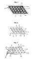
- each microelectrode 11 of the matrix 1 comprises an applicator conductor 21 intended to be applied against a living tissue and is able to serve as a stimulation microelectrode, to send it a stimulation signal. In this conductor 21 therefore passes the stimulation current.
- This conductor is isolated from the conductors of the other electrodes, and is isolated in part from the living tissue.
- Each microelectrode conductor 21 has a section 210 of local application to the living tissue, which is its portion facing the living tissue and to touch it, for example formed by the end of the conductor 21 and for example circular.
- Each microelectrode conductor 21 also has a generally individual external access 13 enabling the connection of an electrical circuit to the support 40 of the matrix 1.
- the spacing pitch between the microelectrodes 11 can be fixed at a determined value for the entire matrix. or have different values for different regions of the matrix.
- the ports 13 are generally isolated from each other at the level of the matrix support.
- One or more additional conductive surfaces 3 are disposed near some or all of the microelectrodes 11.
- Each surface 3 and the microelectrodes 11 are positioned to be able to be applied together against the living tissue, and the surface 3 serves to return the stimulation current. sent by a neighboring microelectrode by focusing it close to it.
- the sections 210 and the surface 3 are generally turned towards the same side with respect to the fabric.
- the accesses 13 to the stimulating microelectrodes 11, the conductors 21 and the sections 210 are electrically isolated from the surface 3, for example by going through layers different from that of the surface 3, above or below it.
- the conductive sections 210 and the conductive surface 3 are bare on the application side against or in the living tissue.
- the surface 3 therefore comprises conductive zones 31 located in the vicinity of certain microelectrode application sections 210, which are interconnected to be substantially equipotential.
- the surface 3 serves as a common focusing means for a plurality of different microelectrode application sections 11.
- the grid or additional surface 3 is not at the same potential as the stimulating microelectrodes 11, which is not the case for the document [8] WO 2005/087 309 , where the goal is to homogenize the stimulation and therefore where the potential is the same on all the microelectrodes of the same stimulation site.
- Each microelectrode 11 generally forms a single stimulation site. However, several microelectrodes can be selected simultaneously for stimulation, which corresponds to the simultaneous use of several stimulation sites.
- Each local application section 210 generally forms a single stimulation site.
- the additional surface 3 or gate is put by its access 33, 35 to an electrical potential generally different from the potential sent to the microelectrodes 11 by their access 13, for example for stimulation by the application section 210 of the microelectrode 11 having been selected .
- the potential of the additional surface 3 is usually set to zero volts but can be set to a value other than zero Volts.
- the additional surface may provide complete or partial return of the stimulation current delivered by the microelectrodes 11 selected for stimulation.
- a single additional surface 3 is provided in common for all the microelectrodes 11.
- a plurality of additional surfaces 3 may be used individually or together preferably at the same potential. There may also be several additional 3, brought to different potentials, for example at least 0.1 millivolt (0.1 mV).
- the potential of the at least one additional surface 3 is different from the potential of at least one microelectrode 11 of said determined plurality of microelectrodes 11, for example of at least 0.1 millivolt (0.1 mV).
- the number of additional surfaces used will preferably be less than one-tenth of the number of microelectrodes 11 of the matrix that can be selected for stimulation in the particular field of application.
- the additional surface is formed by a conductive grid 3 inserted between the microelectrodes 11 while surrounding them.
- the grid 3 comprises meshes 31 forming the conductive zones surrounding the microelectrodes 11, these zones 31 being connected in a conductive manner to each other by the nodes and branches 32 of the grid 3.
- the grid 3 comprises meshes 31 arranged in the space between neighboring microelectrodes 11.
- each mesh 31 or opening 36 surrounds a single associated microelectrode 11.
- Each mesh may however surround a plurality of microelectrodes.
- Each stimulation microelectrode 11 and its associated conductor 21 are electrically isolated from the surface 3.
- the surface 3 requires only one outer conductor 35 for the feedback of the stimulation signal sent by one of the stimulation microelectrodes 11 to the living tissue and a single access terminal 33 for connecting the surface 3 to the outer conductor 35 back. Therefore, it is dispensed with having to insert an additional access conductor between the stimulation microelectrodes 11 for the feedback of the stimulation signal.
- the stimulation microelectrode matrix 11 provided with the surface 3 and their access points 13 and 33 can be provided in a removable autonomous module 1, having in its input-output electrical interface circuit 16 with the external electrical accesses. 13 to the microelectrode 11 and the access terminal 33 to the surface 3.
- This autonomous module 1 can be mounted on a receptacle 4 having terminals 41 of electrical connection respectively accesses 13 microelectrode stimulation 11 and the terminal 35 electrical connection at access 33.
- This module 1 can also contain all or part of the recording and stimulation electronics, especially in the case of implants.
- both spatially focal and homogeneous stimulation of living tissue around the stimulating microelectrode 11 is obtained.
- the problem of focusing stimulations is solved technologically very simple with a single counter electrode formed by the surface 3 ensuring the return of the current, even if several microelectrodes 11 simultaneously stimulate.
- the invention thus makes it possible to introduce the notion of a restricted stimulation pixel to each stimulation microelectrode 11, which may be of paramount importance in the construction of retinal implants, where each zone of the retina must be stimulated locally by uncorrelated to other regions.
- the invention eliminates multipolar stimulations that require multiplying the number of stimulating electrodes, which require more current to activate the cells, and which create non-homogeneous areas of stimulation.
- the microelectrodes 11 have for example a regular layout, such as for example in lines and columns orthogonal to the figure 3 , the grid 3 can then be formed of orthogonal rectilinear lines passing in the spaces between the stimulation microelectrodes 11.
- the microelectrodes 11 and the grid 3 could have any other arrangement.
- the stimulation microelectrodes 11 are distributed in an application region 14 of the stimulation device against the living tissue, this application region 14 being delimited by the stimulation microelectrodes located at the edge of the matrix 1. Access 33 to the surface 3 is generally outside the region 14 for application of the microelectrodes 11, without passing between the stimulation microelectrodes 11, unlike the devices described above of the state of the art. However, a direct access to the surface 3 is possible outside the plane of the microelectrodes 11, for example through the thickness of the support of the microelectrodes.
- a remote mass of the stimulation microelectrodes 11 and the surface 3 may be provided in addition to the surface 3 for the return of the stimulation current.
- the conductivity of the distant mass is higher than that of the surface 3, the stimulation may be less focal than in the absence of the distant mass.
- Sections 210 21 for application of stimulation microelectrodes 11 as well as surface 3 may be written in any shape, for example planar, but also curved.
- the surface 3 may optionally be inserted on a support different from that of the microelectrodes 11, for example in the case of in vivo 3D applications.
- the surface 3 is in the form of a grid according to the figure 3 , with microelectrode application sections 21 of stimulation aligned in a horizontal line, each section 210 being surrounded by a mesh 31, the grid 3 may comprise other meshes 32 surrounding no microelectrode.
- the conductive additional surface 3 is continuous in the region 14 with openings 36 for passage of the sections 210 of the microelectrodes 11, separated by a determined distance from the latter and for example of a shape corresponding to them.
- the conductive zones 31 in the vicinity of the sections 210 each surround a section 210 at a distance therefrom.
- the conductive areas 31 are for example of shape corresponding to that of the sections 210, for example annular for circular sections 210.
- the zones 31 in the vicinity of the sections 210 are connected to each other by equally conductive tabs 37, for example in two intersecting directions in the region 14, these tabs 37 forming part of the surface 3 to be applied or not against the fabric alive and can be rectilinear or not.
- the zones 31 in the vicinity of the sections 210 are connected to each other by external conductors 38 at the surface 3 and not applied against the living tissue when the matrix 1 and the surface 3 are applied.
- the outer conductors 38 are connected to the access 33.
- the zones 31 in the vicinity of the sections 210 comprise branches 39 extending between sections 210 following a determined continuous path passing close to several successive sections 210 situated on the same side, for example between several rows of sections 210.
- the branches 39 are electrically in parallel being connected to each other, for example by a cross member 50, this cross member 50 forming part of the surface 3 to be applied against the living tissue and which may be rectilinear or not and / or similar connecting means 52 to drivers 38 may be provided.
- the branches 39 are for example rectilinear and physically parallel to each other.
- At least one of the branches 39 further comprises transverse extensions 51 between two successive sections 210 situated on the same side of the branch 39. These extensions 51 are for example alternate along the branch 39. These extensions. In the example shown, when several branches 39 are provided, the extensions 51 of a branch 39 do not touch the other branches 39 and in addition alternate a branch 39 to the neighboring branch.
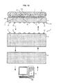
- the stimulation device 8 comprises a stimulus generation system 4, for example formed by a specific application integrated circuit (ASIC), connected on the one hand to the microelectrode access terminals 13 of the matrix 1 and to the surface access terminal 33 and on the other hand an acquisition, stimulation and control system provided with a man-machine interface 6, for example formed by a computer.
- the matrix 1 is applied by its region 14, which comprises the sections 210 of the stimulation microelectrodes 11 and the surface 3, against the living tissue T having N neurons in vitro.
- Matrix 1 via the system 4 under the control of the system 5, sends stimulation signals, having been predetermined on the interface 6, as represented by the vertical arrows directed upwards to the figure 7 .
- the matrix 1 can also take the activity of the living tissue T in response or not to the stimulation signals, which is transmitted to the system 4, then to the system 5 so that it can be restored on the interface 6, as represented by the vertical arrows. headed down to the figure 7 .
- the microelectrode matrix 1 according to the invention could also serve as a reference electrode for measuring the variations of potentials in a living tissue reflecting the electrical activities of excitable cells making up this tissue.
- the matrix can also be applied to tissue in vivo, for functional rehabilitation (for example, hearing, vision, neurodegenerative or cardiac diseases) or for exploration of the central nervous system or other types of systems (basic research) .
- the focus of extracellular stimulation is directly related to the stiffness of the potential field around the stimulating electrode: the steeper this field is (ie, increases rapidly with distance), the more current is required to stimulate at a high rate. distance.
- focusing a stimulation amounts to focusing the potential field around the stimulation electrode.
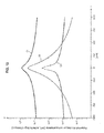
- the figures 11 , 12 , 13 show the evolution of the potential field for different electrode configurations.
- the figure 11 shows the evolution of the potential V (in absolute value) on a line passing 50 microns above the electrodes, for monopolar (curve C1), bipolar (C2 curve), and tripolar (C3 curve) stimulations.
- Monopolar stimulation consists of passing the current between an electrode and a distant mass
- bipolar stimulation consists in passing the current between two neighboring electrodes
- a tripolar stimulation consists of injecting a current into an electrode and returning half of the current in two electrodes located on both sides.
- the three gray disks D1, D2, D3 indicate the positions at 0 ⁇ m, -50 ⁇ m and + 50 ⁇ m of the electrodes aligned along the x-axis of the abscissae in the three-pole case.
- the multipole configurations are more focal but the field is not homogeneous around the electrodes and in particular has blind areas where the cells, yet close to the electrodes, will not be stimulated.
- the potential obtained by the C5 curve is continuous and monotonic as a function of the distance to the stimulating microelectrode.
- the potential field is identical to that C1 generated in monopolar configuration and the focus of the stimulation is not improved.
- the stimulation is more focal only monopolar, but for the same current delivered, the electric potential is much lower and therefore less effective.
- the present invention with a ground grid according to the C5 curve gives a very focal stimulation, and an amplitude of the potential very close to the amplitude obtained in monopolar close to the stimulation electrode.
- the ground gate better focuses the potential than the ring of the second configuration: the attenuation of the curve C5 is greater than that of the curve C4.
- This solution therefore has three advantages over the second configuration: 1) not to duplicate the number of electrodes, 2) to require less current for an identical amplitude of the potential close to the electrode, which is important in view because it is difficult to design small electrodes that do not degrade for high currents, and 3) a better focus potential from a few hundred microns.
- Another characteristic of the invention relates to the surface conductivity of the interface between the ground grid or, more generally, the surface 3 and the electrolyte, it being specified that the conductivity of the metal constituting the ground grid is not considered. but of the conductivity of the electrochemical interface metal / physiological liquid or metal / fabric.
- the surface conductivities are considered for signal frequencies between 10 and 100000 Hz and in particular 100 Hz to 1000 Hz, the standard frequency being 1000 Hz.
- conductivity is the conductivity per unit of geometrical surface and not of real surface. Indeed, a rough or porous interface will have a real surface (deployed / developed) larger than the same smooth geometric surface.
- Conductivity values of the order of 400 S / m 2 are obtained, for example, from white platinum conductive parts.
- Conductivity values of the order of 40000 S / m 2 are obtained, for example, from conductive parts in black-treated platinum.
Landscapes
- Health & Medical Sciences (AREA)
- Life Sciences & Earth Sciences (AREA)
- Animal Behavior & Ethology (AREA)
- Engineering & Computer Science (AREA)
- Biomedical Technology (AREA)
- Veterinary Medicine (AREA)
- Public Health (AREA)
- General Health & Medical Sciences (AREA)
- Radiology & Medical Imaging (AREA)
- Nuclear Medicine, Radiotherapy & Molecular Imaging (AREA)
- Neurology (AREA)
- Heart & Thoracic Surgery (AREA)
- Neurosurgery (AREA)
- Surgery (AREA)
- Molecular Biology (AREA)
- Medical Informatics (AREA)
- Physics & Mathematics (AREA)
- Pathology (AREA)
- Biophysics (AREA)
- Pain & Pain Management (AREA)
- Cardiology (AREA)
- Electrotherapy Devices (AREA)
Claims (30)
- Vorrichtung zur Stimulation eines lebenden Gewebes, die eine Matrix (1) von Mikroelektroden (11) umfasst, die entsprechend einer festgelegten Konfiguration nebeneinander angeordnet sind, wobei jede Mikroelektrode einen Abschnitt (210) zur lokalen Anwendung auf das lebende Gewebe und eine Leitung (21) zur Zuführung eines Stimulationssignals umfasst und für die Anwendung eines elektrischen Stimulationssignals auswählbar ist, wobei
die Mikroelektroden (11) voneinander isoliert sind,
die Leitungen (21) zur Zuführung eines Stimulationssignals voneinander isoliert sind,
die Abschnitte (210) zur lokalen Anwendung voneinander isoliert sind,
eine Anzahl leitender Bereiche (31), jeweils für eine festgelegte Anzahl Mikroelektroden (11), benachbart zu der Anzahl Abschnitte (210) zur lokalen Anwendung der festgelegten Mikroelektroden (11) der Matrix positioniert sind, wobei sie von den Abschnitten (210) zur lokalen Anwendung isoliert sind,
dadurch gekennzeichnet, dass
die Anzahl leitender Bereiche (31) Teil einer leitenden Fläche (3) sind, die zusätzlich zu den Mikroelektroden (11) und von den Mikroelektroden (11) verschieden ist, wobei die zusätzliche leitende Fläche (3) dazu dient, ganz oder teilweise auf das lebende Gewebe aufgesetzt zu werden,
Verbindungsmittel (32, 37, 38, 50, 52) vorgesehen sind, um eine elektrische Verbindung zwischen der Anzahl leitender Bereiche (31) der zusätzlichen Fläche (3) bereitzustellen, und dies für die gesamte festgelegte Anzahl voneinander isolierter Mikroelektroden (11), damit die leitenden Bereiche (31) der zusätzlichen Fläche (3) im Wesentlichen equipotential sind,
die zusätzliche leitende Fläche (3) außerdem mit wenigstens einem Anschluss (33) verbunden ist, der dafür vorgesehen ist, an eine externe Leitung (35) zur wenigstens teilweisen Rückführung des Stimulationssignals angeschlossen zu werden, und dafür ausgebildet ist, ausgehend von wenigstens einer der festgelegten Anzahl Mikroelektroden (11) eine fokussierte Stimulation bereitzustellen und als gemeinsames Fokussierungsmittel für mehrere Anwendungsabschnitte (210) von verschiedenen und festgelegten Mikroelektroden (11) zu dienen. - Vorrichtung nach Anspruch 1, dadurch gekennzeichnet, dass sie eine einzige zusätzliche leitende Fläche (3) umfasst.
- Vorrichtung nach einem der vorhergehenden Ansprüche, dadurch gekennzeichnet, dass die Zahl zusätzlicher Flächen (3) kleiner ist als ein Zehntel der Zahl Mikroelektroden (11) der Matrix.
- Vorrichtung nach einem der Ansprüche 1 bis 3, dadurch gekennzeichnet, dass mehrere zusätzliche Flächen (3) vorhanden sind, die im Wesentlichen equipotential sind.
- Vorrichtung nach einem der Ansprüche 1 bis 3, dadurch gekennzeichnet, dass mehrere zusätzliche Flächen (3) mit im Wesentlichen verschiedenen Potentialen vorhanden sind.
- Vorrichtung nach einem der vorhergehenden Ansprüche, dadurch gekennzeichnet, dass das Potential der wenigstens einen zusätzlichen Fläche (3) vom Potential wenigstens einer Mikroelektrode (11) der festgelegten Anzahl Mikroelektroden (11) verschieden ist.
- Vorrichtung nach einem der vorhergehenden Ansprüche, dadurch gekennzeichnet, dass die zusätzliche leitende Fläche (3) in denselben Träger integriert ist wie die Mikroelektroden (11).
- Vorrichtung nach einem der vorhergehenden Ansprüche, dadurch gekennzeichnet, dass die zusätzliche leitende Fläche (3) in einen Träger integriert ist, der verschieden von demjenigen der Mikroelektroden (11) ist.
- Vorrichtung nach einem der vorhergehenden Ansprüche, dadurch gekennzeichnet, dass die zusätzliche leitende Fläche (3) die Form eines Gitters hat, dessen leitende Bereiche durch Maschen (31) gebildet werden, die um Mikroelektroden (11) herum verlaufen, wobei die Verbindungsmittel auf der zusätzlichen Fläche durch die Kreuzungen (32) der Maschen (31) miteinander gebildet werden.
- Vorrichtung nach Anspruch 9, dadurch gekennzeichnet, dass von den Maschen (31), die um Mikroelektroden (11) herum verlaufen, jede um eine einzige Mikroelektrode (11) herum verläuft.
- Vorrichtung nach einem der Ansprüche 9 und 10, dadurch gekennzeichnet, dass das Gitter (3) durch schneidende geradlinige Linien gebildet wird.
- Vorrichtung nach einem der Ansprüche 9 bis 11, dadurch gekennzeichnet, dass jede der Maschen (31) des Gitters (3), die um eine Mikroelektrode (11) herum verläuft, ein Stimulationspixel bildet, das auf den von dieser Masche (31) begrenzten Raum eingeschränkt ist.
- Vorrichtung nach einem der vorhergehenden Ansprüche, dadurch gekennzeichnet, dass die zusätzliche leitende Fläche (3) zwischen Mikroelektroden (11) hindurch verläuft.
- Vorrichtung nach einem der vorhergehenden Ansprüche, dadurch gekennzeichnet, dass die zusätzliche leitende Fläche (3) Mikroelektroden (11) umgibt.
- Vorrichtung nach einem der vorhergehenden Ansprüche, dadurch gekennzeichnet, dass die zusätzliche leitende Fläche (3) mit Öffnungen (36) für den Durchgang der Abschnitte (210) zur lokalen Anwendung der Mikroelektroden (11) versehen ist.
- Vorrichtung nach einem der vorhergehenden Ansprüche, dadurch gekennzeichnet, dass die zusätzliche leitende Fläche (3) Äste (39) umfasst, die zwischen Mikroelektroden (11) elektrisch parallel geschaltet sind und von denen jeder benachbart zu mehreren Mikroelektroden (11) verläuft.
- Vorrichtung nach einem der Ansprüche 1 bis 16, dadurch gekennzeichnet, dass die Mittel (32, 37, 50) zur elektrischen Verbindung zwischen den verschiedenen leitenden Bereichen (31) wenigstens teilweise in der zusätzlichen leitenden Fläche (3) angeordnet sind.
- Vorrichtung nach einem der Ansprüche 1 bis 16, dadurch gekennzeichnet, dass die Mittel (38, 52) zur elektrischen Verbindung wenigstens teilweise außerhalb der zusätzlichen leitenden Fläche (3), innerhalb oder außerhalb eines Trägers der zusätzlichen leitenden Fläche (3) oder in einer zusätzlichen äußeren elektrischen Schaltung angeordnet sind.
- Vorrichtung nach einem der vorhergehenden Ansprüche, dadurch gekennzeichnet, dass die zusätzliche leitende Fläche (3) eine elektrische Oberflächenleitfähigkeit an der Schnittstelle zum lebenden Gewebe hat, die größer oder gleich 100 S/m2 bei einer Frequenz von 100 Hz bis 1000 Hz ist.
- Vorrichtung nach einem der vorhergehenden Ansprüche, dadurch gekennzeichnet, dass die zusätzliche leitende Fläche (3) eine elektrische Oberflächenleitfähigkeit an der Schnittstelle zum lebenden Gewebe hat, die größer oder gleich 1000 S/m2 bei einer Frequenz von 100 Hz bis 1000 Hz ist und vorzugsweise größer oder gleich 40000 S/m2 bei einer Frequenz von 100 Hz bis 1000 Hz.
- Vorrichtung nach einem der vorhergehenden Ansprüche, dadurch gekennzeichnet, dass die Mikroelektrodenmatrix (11) ein Abstandsmaß zwischen Mikroelektroden umfasst, wobei die leitenden Bereiche (31) der zusätzlichen Fläche (3) in einem Abstand von der Anzahl Mikroelektroden (11) verlaufen, der kleiner oder gleich dem Fünffachen des maximalen Abstandsmaßes zwischen Mikroelektroden ist und vorzugsweise in einem Abstand, der kleiner oder gleich dem minimalen Abstandsmaß zwischen Mikroelektroden ist.
- Vorrichtung nach einem der vorhergehenden Ansprüche, dadurch gekennzeichnet, dass die leitenden Bereiche (31) der zusätzlichen Fläche (3) in einem Abstand von der Anzahl Mikroelektroden verlaufen, der kleiner oder gleich 500 µm ist.
- Vorrichtung nach einem der vorhergehenden Ansprüche, dadurch gekennzeichnet, dass sie eine Vielzahl elektrischer Anschlüsse (13) für die Mikroelektroden (11) umfasst, die jeweils der Vielzahl Mikroelektroden (11) der Matrix (1) zugeordnet sind, wobei der Anschluss (33) der zusätzlichen leitenden Fläche (3) nur einmal vorhanden und von den elektrischen Anschlüssen (13) der Mikroelektroden (11) verschieden ist.
- Vorrichtung nach einem der Ansprüche 1 bis 22, dadurch gekennzeichnet, dass sie eine Vielzahl elektrischer Anschlüsse (13) für die Mikroelektroden (11) umfasst, die jeweils der Vielzahl Mikroelektroden (11) der Matrix (1) zugeordnet sind, wobei der Anschluss (33) der zusätzlichen leitenden Fläche (3) mehrfach vorhanden und von den elektrischen Anschlüssen (13) der Mikroelektroden (11) verschieden ist.
- Vorrichtung nach einem der vorhergehenden Ansprüche, dadurch gekennzeichnet, dass die Mikroelektroden (15), die sich am Rand der Matrix (1) befinden, einen Bereich (14) zum Aufsetzen auf das lebende Gewebe abgrenzen, wobei der Anschluss (33) der Fläche (3) sich außerhalb des Bereichs (14) zum Aufsetzen der Mikroelektroden (11) befindet.
- Vorrichtung nach einem der Ansprüche 1 bis 24, dadurch gekennzeichnet, dass die Mikroelektroden (15), die sich am Rand der Matrix (1) befinden, einen Bereich (14) zum Aufsetzen auf das lebende Gewebe abgrenzen, wobei der Anschluss (33) der Fläche (3) sich innerhalb des Bereichs (14) zum Aufsetzen der Mikroelektroden (11) befindet.
- Vorrichtung nach einem der vorhergehenden Ansprüche, dadurch gekennzeichnet, dass es außerdem Folgendes umfasst: ein erstes System (4) zum Erzeugen eines elektrischen Stimulus, zur Verstärkung und zum Multiplexen der mit den Mikroelektroden aufgenommenen Signale, das mit den Mikroelektroden (11) und dem Anschluss (33) der Fläche (3) verbunden ist, und ein zweites System (5) zum Erfassen und zur Steuerung, das mit einer Mensch-Maschine-Schnittstelle (6) zur Steuerung des ersten Systems (4) ausgestattet ist, um an wenigstens eine vorausgewählte der Mikroelektroden (11) ein auf der Mensch-Maschine-Schnittstelle (6) vorgegebenes Stimulationssignal zu senden und die Antwort des lebenden Gewebes auf das Stimulationssignal aufzunehmen und sie auf der Mensch-Maschine-Schnittstelle (6) wiederzugeben.
- In-Vitro-Verwendung der Vorrichtung nach einem der vorhergehenden Ansprüche, um sie in Kontakt mit einem unter den folgenden Objekten einzusetzen: ein Zellpräparat, ein Explant, ein Laborsystem, ein isoliertes lebendes Organ, ein Teil eines isolierten lebenden Organs.
- Abnehmbare Einheit, die dafür vorgesehen ist, in der Vorrichtung nach einem der Ansprüche 1 bis 27 montiert zu werden, dadurch gekennzeichnet, dass sie auf einem einzigen abnehmbaren Modul oder verteilt auf mehrere getrennte abnehmbare Module Folgendes umfasst: die Mikroelektrodenmatrix (1), die zusätzliche Fläche (3) und eine elektrische Eingangs-Ausgangs-Schnittstellenschaltung (16) für die elektrische Verbindung der Mikroelektroden (11) und der zusätzlichen Fläche (3) mit dem Äußeren, wobei diese Folgendes umfasst: eine Vielzahl elektrischer Anschlusspunkte (13) für jeweils die Vielzahl Mikroelektroden (11) der Matrix (1) und einen Anschlusspunkt (33) für die zusätzliche Fläche (3), der von den elektrischen Anschlusspunkten (13) für die Mikroelektroden (11) verschieden ist.
- Verwendung der Vorrichtung nach einem der Ansprüche 1 bis 27 für das Aufzeichnen von Signalen, die von einem lebenden Gewebe ausgegeben werden, bei dem es sich um eines der folgenden handelt: ein Zellpräparat, ein Explant, ein Laborsystem, ein isoliertes lebendes Organ, ein Teil eines isolierten lebenden Organs.
Applications Claiming Priority (2)
| Application Number | Priority Date | Filing Date | Title |
|---|---|---|---|
| FR0707369A FR2922460B1 (fr) | 2007-10-22 | 2007-10-22 | "dispositif de stimulation d'un tissu vivant par microelectrodes,ses modules amovibles et utilisation" |
| PCT/EP2008/064133 WO2009053333A1 (fr) | 2007-10-22 | 2008-10-20 | Dispositif de stimulation d'un tissu vivant par microelectrodes, ses module amovible et utilisation |
Publications (2)
| Publication Number | Publication Date |
|---|---|
| EP2217322A1 EP2217322A1 (de) | 2010-08-18 |
| EP2217322B1 true EP2217322B1 (de) | 2013-08-21 |
Family
ID=39184674
Family Applications (1)
| Application Number | Title | Priority Date | Filing Date |
|---|---|---|---|
| EP08842542.6A Active EP2217322B1 (de) | 2007-10-22 | 2008-10-20 | Vorrichtung zur stimulierung von lebendem gewebe durch mikroelektroden und entfernbares modul und seine verwendung |
Country Status (9)
| Country | Link |
|---|---|
| US (1) | US8352045B2 (de) |
| EP (1) | EP2217322B1 (de) |
| JP (1) | JP5444235B2 (de) |
| CA (1) | CA2702277C (de) |
| DK (1) | DK2217322T3 (de) |
| ES (1) | ES2435787T3 (de) |
| FR (1) | FR2922460B1 (de) |
| PT (1) | PT2217322E (de) |
| WO (1) | WO2009053333A1 (de) |
Families Citing this family (21)
| Publication number | Priority date | Publication date | Assignee | Title |
|---|---|---|---|---|
| WO2010107707A2 (en) | 2009-03-17 | 2010-09-23 | Savage Walter T | External defibrillator |
| DE102010019597B4 (de) * | 2010-05-05 | 2014-05-28 | Cortec Gmbh | Verfahren zum Herstellen einer Elektrodenstruktur sowie Elektrodenstruktur für eine neuronale Schnittstelle |
| US8473072B2 (en) * | 2010-06-08 | 2013-06-25 | Axelgaard Manufacturing Company, Ltd. | Customizable medical electrode |
| EP2394696A1 (de) | 2010-06-09 | 2011-12-14 | Centre National de la Recherche Scientifique (CNRS) | Vorrichtung zur Stimulierung oder Aufzeichnung eines Signals an oder von einem lebenden Gewebe |
| US10124160B2 (en) | 2012-05-16 | 2018-11-13 | University Of Utah Research Foundation | Charge steering high density electrode array |
| CN102680526B (zh) * | 2012-05-16 | 2014-07-02 | 清华大学 | 单细胞阵列微芯片及其制造、电测量和电穿孔方法 |
| US9907970B2 (en) | 2013-06-14 | 2018-03-06 | Cardiothrive, Inc. | Therapeutic system and method using biphasic or multiphasic pulse waveform |
| US9833630B2 (en) | 2013-06-14 | 2017-12-05 | Cardiothrive, Inc. | Biphasic or multiphasic pulse waveform and method |
| US9616243B2 (en) | 2013-06-14 | 2017-04-11 | Cardiothrive, Inc. | Dynamically adjustable multiphasic defibrillator pulse system and method |
| US9656094B2 (en) | 2013-06-14 | 2017-05-23 | Cardiothrive, Inc. | Biphasic or multiphasic pulse generator and method |
| US20140371566A1 (en) * | 2013-06-14 | 2014-12-18 | Cardiothrive, Inc. | Conforming patient contact interface and method for using same |
| US10279189B2 (en) | 2013-06-14 | 2019-05-07 | Cardiothrive, Inc. | Wearable multiphasic cardioverter defibrillator system and method |
| US10149973B2 (en) | 2013-06-14 | 2018-12-11 | Cardiothrive, Inc. | Multipart non-uniform patient contact interface and method of use |
| WO2016062637A1 (fr) * | 2014-10-23 | 2016-04-28 | Chambre De Commerce Et D'industrie De Region Paris Ile De France (Esiee Paris) | Micro-électrodes démontables |
| US20180306770A1 (en) | 2016-11-16 | 2018-10-25 | Purdue Research Foundation | Biological sensing system having micro-electrode array |
| US10828500B2 (en) | 2017-12-22 | 2020-11-10 | Cardiothrive, Inc. | External defibrillator |
| JP7565913B2 (ja) * | 2018-09-05 | 2024-10-11 | アクソシム, インコーポレイテッド | マイクロ電極アレイおよびその使用方法 |
| JP2020092762A (ja) * | 2018-12-11 | 2020-06-18 | 日本電信電話株式会社 | 電気刺激装置 |
| KR102380218B1 (ko) * | 2018-12-13 | 2022-03-30 | 주식회사 바른바이오 | 두피 자극을 위한 미세전류 장치 |
| WO2023038539A1 (ru) * | 2021-09-07 | 2023-03-16 | Общество с ограниченной ответственностью "Косима" (ООО "Косима") | Неинвазивная электроидная матрица спинального нейропротеза и способ ее применения |
| CN115637225A (zh) * | 2022-11-07 | 2023-01-24 | 北京载愈生物科技有限公司 | 一种微电极结构及其制备方法 |
Family Cites Families (24)
| Publication number | Priority date | Publication date | Assignee | Title |
|---|---|---|---|---|
| US4969468A (en) * | 1986-06-17 | 1990-11-13 | Alfred E. Mann Foundation For Scientific Research | Electrode array for use in connection with a living body and method of manufacture |
| US5810725A (en) * | 1993-04-16 | 1998-09-22 | Matsushita Electric Industrial Co., Ltd. | Planar electrode |
| US5411540A (en) * | 1993-06-03 | 1995-05-02 | Massachusetts Institute Of Technology | Method and apparatus for preferential neuron stimulation |
| US6297025B1 (en) * | 1994-06-13 | 2001-10-02 | Matsushita Electric Industrial Co., Ltd | Measurement of complete electrical waveforms of tissue or cells |
| US5563067A (en) * | 1994-06-13 | 1996-10-08 | Matsushita Electric Industrial Co., Ltd. | Cell potential measurement apparatus having a plurality of microelectrodes |
| DE19529371C3 (de) * | 1995-08-10 | 2003-05-28 | Nmi Univ Tuebingen | Mikroelektroden-Anordnung |
| US6132683A (en) * | 1998-12-23 | 2000-10-17 | Matsushita Electric Industrial Co., Ltd. | Cell potential measuring electrode and measuring apparatus using the same |
| US5938689A (en) * | 1998-05-01 | 1999-08-17 | Neuropace, Inc. | Electrode configuration for a brain neuropacemaker |
| US6324429B1 (en) * | 1998-05-08 | 2001-11-27 | Massachusetts Eye And Ear Infirmary | Chronically implantable retinal prosthesis |
| DE10151650A1 (de) * | 2001-10-17 | 2003-05-08 | Univ Eberhard Karls | Elektrodenanordnung zur elektrischen Stimulation von biologischem Material sowie Multielektrodenarray zur Verwendung in einer solchen |
| CN100344960C (zh) * | 2001-12-17 | 2007-10-24 | 清华大学 | 刺激动物细胞并记录其生理信号的装置及其生产使用方法 |
| US7221981B2 (en) * | 2002-03-28 | 2007-05-22 | Northstar Neuroscience, Inc. | Electrode geometries for efficient neural stimulation |
| US7006859B1 (en) * | 2002-07-20 | 2006-02-28 | Flint Hills Scientific, L.L.C. | Unitized electrode with three-dimensional multi-site, multi-modal capabilities for detection and control of brain state changes |
| JP2006528041A (ja) * | 2003-06-12 | 2006-12-14 | ザ・ユーエービー・リサーチ・ファウンデーション | データを記録して分析するための又は組織を刺激するための多重電極配列及びシステム |
| US20050137673A1 (en) * | 2003-11-07 | 2005-06-23 | Lilip Lau | Cardiac harness having electrodes and epicardial leads |
| US20050203366A1 (en) * | 2004-03-12 | 2005-09-15 | Donoghue John P. | Neurological event monitoring and therapy systems and related methods |
| DE102004012564A1 (de) * | 2004-03-12 | 2005-10-06 | Iip-Technologies Gmbh | Stimulationselektrode |
| US7177702B2 (en) * | 2004-03-12 | 2007-02-13 | Scimed Life Systems, Inc. | Collapsible/expandable electrode leads |
| EP1723983B1 (de) * | 2005-05-20 | 2013-07-10 | Imec | Sonde für die elektrische Stimulation und Bestimmung der Aktivität von erregbaren Zellen |
| US8024022B2 (en) * | 2005-05-25 | 2011-09-20 | Alfred E. Mann Foundation For Scientific Research | Hermetically sealed three-dimensional electrode array |
| US20070142863A1 (en) * | 2005-12-15 | 2007-06-21 | Kerry Bradley | Apparatus and methods for stimulating tissue |
| EP2035079B1 (de) * | 2006-06-19 | 2020-09-02 | Second Sight Medical Products, Inc. | Elektrode von erhöhter stabilität und verfahren zu ihrer herstellung |
| JP5011597B2 (ja) * | 2006-07-28 | 2012-08-29 | メド−エル エレクトロ−メディツィニシェ ゲレーテ ゲゼルシャフト ミット ベシュレンクテル ハフツング | 層状電極アレイ及びケーブル |
| CN104224171B (zh) * | 2010-03-17 | 2017-06-09 | 伊利诺伊大学评议会 | 基于生物可吸收基质的可植入生物医学装置 |
-
2007
- 2007-10-22 FR FR0707369A patent/FR2922460B1/fr active Active
-
2008
- 2008-10-20 CA CA2702277A patent/CA2702277C/fr active Active
- 2008-10-20 EP EP08842542.6A patent/EP2217322B1/de active Active
- 2008-10-20 PT PT88425426T patent/PT2217322E/pt unknown
- 2008-10-20 WO PCT/EP2008/064133 patent/WO2009053333A1/fr not_active Ceased
- 2008-10-20 ES ES08842542T patent/ES2435787T3/es active Active
- 2008-10-20 US US12/739,069 patent/US8352045B2/en active Active
- 2008-10-20 JP JP2010530418A patent/JP5444235B2/ja active Active
- 2008-10-20 DK DK08842542.6T patent/DK2217322T3/da active
Also Published As
| Publication number | Publication date |
|---|---|
| CA2702277A1 (fr) | 2009-04-30 |
| DK2217322T3 (da) | 2013-12-02 |
| WO2009053333A1 (fr) | 2009-04-30 |
| US8352045B2 (en) | 2013-01-08 |
| JP2011500240A (ja) | 2011-01-06 |
| PT2217322E (pt) | 2013-11-25 |
| US20110208029A1 (en) | 2011-08-25 |
| EP2217322A1 (de) | 2010-08-18 |
| JP5444235B2 (ja) | 2014-03-19 |
| FR2922460B1 (fr) | 2011-11-18 |
| ES2435787T3 (es) | 2013-12-23 |
| CA2702277C (fr) | 2016-02-23 |
| FR2922460A1 (fr) | 2009-04-24 |
Similar Documents
| Publication | Publication Date | Title |
|---|---|---|
| CA2702277C (fr) | Dispositif de stimulation d'un tissu vivant par microelectrodes, ses module amovible et utilisation | |
| Steinmetz et al. | Neuropixels 2.0: A miniaturized high-density probe for stable, long-term brain recordings | |
| Keppeler et al. | Multichannel optogenetic stimulation of the auditory pathway using microfabricated LED cochlear implants in rodents | |
| Shoval et al. | Carbon nanotube electrodes for effective interfacing with retinal tissue | |
| Yoo et al. | Electro-optical neural platform integrated with nanoplasmonic inhibition interface | |
| US10463265B2 (en) | Implantable electrode array | |
| Hottowy et al. | Properties and application of a multichannel integrated circuit for low-artifact, patterned electrical stimulation of neural tissue | |
| EP2946806A1 (de) | Aktive implantierbare medizinische vorrichtung mit automatischer optimierung der konfiguration einer multielektroden-stimulationssonde, insbesondere einer sonde zur selektiven stimulation des vagusnervs | |
| Huan et al. | Carbon fiber electrodes for intracellular recording and stimulation | |
| EP3261709A1 (de) | Vorrichtung zur funktionellen elektrostimulation und elektromyogrammmessung mit vorrichtung zur kurzschliessung und erdung eines elektrodenpaares und zugehörige transkutane elektrode | |
| Kim et al. | Iridium oxide–electrodeposited nanoporous gold multielectrode array with enhanced stimulus efficacy | |
| US20230147961A1 (en) | Implantable Transition Micro-Electrodes | |
| EP2566573B1 (de) | Implantat mit dreidimensionaler form zur elektrischen stimulation einer nervenstruktur | |
| Hofmann et al. | Light induced stimulation and delay of cardiac activity | |
| Vėbraitė et al. | Electrophysiological investigation of intact retina with soft printed organic neural interface | |
| Marx | Neurobiology: rethinking the electrode | |
| EP3250151B1 (de) | Vorrichtung für die prothetische rehabilitation der netzhaut | |
| CN1973918B (zh) | 可植入人体神经系统的簇状刺激微电极阵列 | |
| EP2581108B1 (de) | Über eine multiplexierte Sonde gesteuertes Schaltmodul für ein implantierbares aktives medizinisches Gerät | |
| Neves et al. | The neuroprobes project | |
| Schloesser et al. | Embedded device for simultaneous recording and stimulation for retina implant research | |
| FR2860722A1 (fr) | Dispositif d'electro-stimulation cerebrale ameliore | |
| Song et al. | Microfabricated nerve–electrode interfaces in neural prosthetics and neural engineering | |
| Musa et al. | Design, fabrication and characterization of a neural probe for deep brain stimulation and recording. | |
| Motta et al. | Micromachined probes for deep-brain stimulation |
Legal Events
| Date | Code | Title | Description |
|---|---|---|---|
| PUAI | Public reference made under article 153(3) epc to a published international application that has entered the european phase |
Free format text: ORIGINAL CODE: 0009012 |
|
| 17P | Request for examination filed |
Effective date: 20100505 |
|
| AK | Designated contracting states |
Kind code of ref document: A1 Designated state(s): AT BE BG CH CY CZ DE DK EE ES FI FR GB GR HR HU IE IS IT LI LT LU LV MC MT NL NO PL PT RO SE SI SK TR |
|
| AX | Request for extension of the european patent |
Extension state: AL BA MK RS |
|
| DAX | Request for extension of the european patent (deleted) | ||
| GRAP | Despatch of communication of intention to grant a patent |
Free format text: ORIGINAL CODE: EPIDOSNIGR1 |
|
| GRAS | Grant fee paid |
Free format text: ORIGINAL CODE: EPIDOSNIGR3 |
|
| GRAA | (expected) grant |
Free format text: ORIGINAL CODE: 0009210 |
|
| AK | Designated contracting states |
Kind code of ref document: B1 Designated state(s): AT BE BG CH CY CZ DE DK EE ES FI FR GB GR HR HU IE IS IT LI LT LU LV MC MT NL NO PL PT RO SE SI SK TR |
|
| REG | Reference to a national code |
Ref country code: GB Ref legal event code: FG4D Free format text: NOT ENGLISH |
|
| REG | Reference to a national code |
Ref country code: CH Ref legal event code: EP |
|
| REG | Reference to a national code |
Ref country code: AT Ref legal event code: REF Ref document number: 627708 Country of ref document: AT Kind code of ref document: T Effective date: 20130915 |
|
| REG | Reference to a national code |
Ref country code: IE Ref legal event code: FG4D Free format text: LANGUAGE OF EP DOCUMENT: FRENCH |
|
| REG | Reference to a national code |
Ref country code: DE Ref legal event code: R096 Ref document number: 602008027057 Country of ref document: DE Effective date: 20131017 |
|
| REG | Reference to a national code |
Ref country code: PT Ref legal event code: SC4A Free format text: AVAILABILITY OF NATIONAL TRANSLATION Effective date: 20131118 |
|
| REG | Reference to a national code |
Ref country code: SE Ref legal event code: TRGR |
|
| REG | Reference to a national code |
Ref country code: CH Ref legal event code: NV Representative=s name: MICHELI AND CIE SA, CH |
|
| REG | Reference to a national code |
Ref country code: DK Ref legal event code: T3 Effective date: 20131126 |
|
| REG | Reference to a national code |
Ref country code: NL Ref legal event code: T3 |
|
| REG | Reference to a national code |
Ref country code: ES Ref legal event code: FG2A Ref document number: 2435787 Country of ref document: ES Kind code of ref document: T3 Effective date: 20131223 |
|
| REG | Reference to a national code |
Ref country code: NO Ref legal event code: T2 Effective date: 20130821 |
|
| REG | Reference to a national code |
Ref country code: LT Ref legal event code: MG4D |
|
| PG25 | Lapsed in a contracting state [announced via postgrant information from national office to epo] |
Ref country code: CY Free format text: LAPSE BECAUSE OF FAILURE TO SUBMIT A TRANSLATION OF THE DESCRIPTION OR TO PAY THE FEE WITHIN THE PRESCRIBED TIME-LIMIT Effective date: 20130904 Ref country code: LT Free format text: LAPSE BECAUSE OF FAILURE TO SUBMIT A TRANSLATION OF THE DESCRIPTION OR TO PAY THE FEE WITHIN THE PRESCRIBED TIME-LIMIT Effective date: 20130821 Ref country code: IS Free format text: LAPSE BECAUSE OF FAILURE TO SUBMIT A TRANSLATION OF THE DESCRIPTION OR TO PAY THE FEE WITHIN THE PRESCRIBED TIME-LIMIT Effective date: 20131221 Ref country code: HR Free format text: LAPSE BECAUSE OF FAILURE TO SUBMIT A TRANSLATION OF THE DESCRIPTION OR TO PAY THE FEE WITHIN THE PRESCRIBED TIME-LIMIT Effective date: 20130821 |
|
| PG25 | Lapsed in a contracting state [announced via postgrant information from national office to epo] |
Ref country code: SI Free format text: LAPSE BECAUSE OF FAILURE TO SUBMIT A TRANSLATION OF THE DESCRIPTION OR TO PAY THE FEE WITHIN THE PRESCRIBED TIME-LIMIT Effective date: 20130821 Ref country code: LV Free format text: LAPSE BECAUSE OF FAILURE TO SUBMIT A TRANSLATION OF THE DESCRIPTION OR TO PAY THE FEE WITHIN THE PRESCRIBED TIME-LIMIT Effective date: 20130821 Ref country code: GR Free format text: LAPSE BECAUSE OF FAILURE TO SUBMIT A TRANSLATION OF THE DESCRIPTION OR TO PAY THE FEE WITHIN THE PRESCRIBED TIME-LIMIT Effective date: 20131122 Ref country code: PL Free format text: LAPSE BECAUSE OF FAILURE TO SUBMIT A TRANSLATION OF THE DESCRIPTION OR TO PAY THE FEE WITHIN THE PRESCRIBED TIME-LIMIT Effective date: 20130821 |
|
| PG25 | Lapsed in a contracting state [announced via postgrant information from national office to epo] |
Ref country code: CY Free format text: LAPSE BECAUSE OF FAILURE TO SUBMIT A TRANSLATION OF THE DESCRIPTION OR TO PAY THE FEE WITHIN THE PRESCRIBED TIME-LIMIT Effective date: 20130821 |
|
| PG25 | Lapsed in a contracting state [announced via postgrant information from national office to epo] |
Ref country code: CZ Free format text: LAPSE BECAUSE OF FAILURE TO SUBMIT A TRANSLATION OF THE DESCRIPTION OR TO PAY THE FEE WITHIN THE PRESCRIBED TIME-LIMIT Effective date: 20130821 Ref country code: RO Free format text: LAPSE BECAUSE OF FAILURE TO SUBMIT A TRANSLATION OF THE DESCRIPTION OR TO PAY THE FEE WITHIN THE PRESCRIBED TIME-LIMIT Effective date: 20130821 Ref country code: SK Free format text: LAPSE BECAUSE OF FAILURE TO SUBMIT A TRANSLATION OF THE DESCRIPTION OR TO PAY THE FEE WITHIN THE PRESCRIBED TIME-LIMIT Effective date: 20130821 Ref country code: EE Free format text: LAPSE BECAUSE OF FAILURE TO SUBMIT A TRANSLATION OF THE DESCRIPTION OR TO PAY THE FEE WITHIN THE PRESCRIBED TIME-LIMIT Effective date: 20130821 |
|
| PG25 | Lapsed in a contracting state [announced via postgrant information from national office to epo] |
Ref country code: MC Free format text: LAPSE BECAUSE OF FAILURE TO SUBMIT A TRANSLATION OF THE DESCRIPTION OR TO PAY THE FEE WITHIN THE PRESCRIBED TIME-LIMIT Effective date: 20130821 |
|
| PLBE | No opposition filed within time limit |
Free format text: ORIGINAL CODE: 0009261 |
|
| STAA | Information on the status of an ep patent application or granted ep patent |
Free format text: STATUS: NO OPPOSITION FILED WITHIN TIME LIMIT |
|
| 26N | No opposition filed |
Effective date: 20140522 |
|
| REG | Reference to a national code |
Ref country code: IE Ref legal event code: MM4A |
|
| REG | Reference to a national code |
Ref country code: DE Ref legal event code: R097 Ref document number: 602008027057 Country of ref document: DE Effective date: 20140522 |
|
| PG25 | Lapsed in a contracting state [announced via postgrant information from national office to epo] |
Ref country code: IE Free format text: LAPSE BECAUSE OF NON-PAYMENT OF DUE FEES Effective date: 20131020 |
|
| PG25 | Lapsed in a contracting state [announced via postgrant information from national office to epo] |
Ref country code: TR Free format text: LAPSE BECAUSE OF FAILURE TO SUBMIT A TRANSLATION OF THE DESCRIPTION OR TO PAY THE FEE WITHIN THE PRESCRIBED TIME-LIMIT Effective date: 20130821 |
|
| PG25 | Lapsed in a contracting state [announced via postgrant information from national office to epo] |
Ref country code: LU Free format text: LAPSE BECAUSE OF NON-PAYMENT OF DUE FEES Effective date: 20131020 Ref country code: BG Free format text: LAPSE BECAUSE OF FAILURE TO SUBMIT A TRANSLATION OF THE DESCRIPTION OR TO PAY THE FEE WITHIN THE PRESCRIBED TIME-LIMIT Effective date: 20130821 Ref country code: HU Free format text: LAPSE BECAUSE OF FAILURE TO SUBMIT A TRANSLATION OF THE DESCRIPTION OR TO PAY THE FEE WITHIN THE PRESCRIBED TIME-LIMIT; INVALID AB INITIO Effective date: 20081020 |
|
| PG25 | Lapsed in a contracting state [announced via postgrant information from national office to epo] |
Ref country code: MT Free format text: LAPSE BECAUSE OF FAILURE TO SUBMIT A TRANSLATION OF THE DESCRIPTION OR TO PAY THE FEE WITHIN THE PRESCRIBED TIME-LIMIT Effective date: 20130821 |
|
| REG | Reference to a national code |
Ref country code: FR Ref legal event code: PLFP Year of fee payment: 9 |
|
| REG | Reference to a national code |
Ref country code: FR Ref legal event code: PLFP Year of fee payment: 10 |
|
| REG | Reference to a national code |
Ref country code: FR Ref legal event code: PLFP Year of fee payment: 11 |
|
| P01 | Opt-out of the competence of the unified patent court (upc) registered |
Effective date: 20230630 |
|
| REG | Reference to a national code |
Ref country code: CH Ref legal event code: U11 Free format text: ST27 STATUS EVENT CODE: U-0-0-U10-U11 (AS PROVIDED BY THE NATIONAL OFFICE) Effective date: 20251106 |
|
| PGFP | Annual fee paid to national office [announced via postgrant information from national office to epo] |
Ref country code: NL Payment date: 20251030 Year of fee payment: 18 |
|
| PGFP | Annual fee paid to national office [announced via postgrant information from national office to epo] |
Ref country code: PT Payment date: 20251015 Year of fee payment: 18 |
|
| PGFP | Annual fee paid to national office [announced via postgrant information from national office to epo] |
Ref country code: DE Payment date: 20251126 Year of fee payment: 18 |
|
| PGFP | Annual fee paid to national office [announced via postgrant information from national office to epo] |
Ref country code: GB Payment date: 20251029 Year of fee payment: 18 |
|
| PGFP | Annual fee paid to national office [announced via postgrant information from national office to epo] |
Ref country code: NO Payment date: 20251030 Year of fee payment: 18 |
|
| PGFP | Annual fee paid to national office [announced via postgrant information from national office to epo] |
Ref country code: AT Payment date: 20251029 Year of fee payment: 18 |
|
| PGFP | Annual fee paid to national office [announced via postgrant information from national office to epo] |
Ref country code: FI Payment date: 20251029 Year of fee payment: 18 Ref country code: DK Payment date: 20251029 Year of fee payment: 18 Ref country code: IT Payment date: 20251029 Year of fee payment: 18 |
|
| PGFP | Annual fee paid to national office [announced via postgrant information from national office to epo] |
Ref country code: FR Payment date: 20251030 Year of fee payment: 18 |
|
| PGFP | Annual fee paid to national office [announced via postgrant information from national office to epo] |
Ref country code: BE Payment date: 20251030 Year of fee payment: 18 |
|
| PGFP | Annual fee paid to national office [announced via postgrant information from national office to epo] |
Ref country code: CH Payment date: 20251106 Year of fee payment: 18 Ref country code: SE Payment date: 20251029 Year of fee payment: 18 |
|
| PGFP | Annual fee paid to national office [announced via postgrant information from national office to epo] |
Ref country code: ES Payment date: 20260127 Year of fee payment: 18 |