EP2216808A2 - Method of making a heat sink - Google Patents
Method of making a heat sink Download PDFInfo
- Publication number
- EP2216808A2 EP2216808A2 EP09004891A EP09004891A EP2216808A2 EP 2216808 A2 EP2216808 A2 EP 2216808A2 EP 09004891 A EP09004891 A EP 09004891A EP 09004891 A EP09004891 A EP 09004891A EP 2216808 A2 EP2216808 A2 EP 2216808A2
- Authority
- EP
- European Patent Office
- Prior art keywords
- conductive plate
- heat conductive
- protrusion
- heat
- fin assembly
- Prior art date
- Legal status (The legal status is an assumption and is not a legal conclusion. Google has not performed a legal analysis and makes no representation as to the accuracy of the status listed.)
- Withdrawn
Links
Images





Classifications
-
- H—ELECTRICITY
- H05—ELECTRIC TECHNIQUES NOT OTHERWISE PROVIDED FOR
- H05K—PRINTED CIRCUITS; CASINGS OR CONSTRUCTIONAL DETAILS OF ELECTRIC APPARATUS; MANUFACTURE OF ASSEMBLAGES OF ELECTRICAL COMPONENTS
- H05K7/00—Constructional details common to different types of electric apparatus
- H05K7/20—Modifications to facilitate cooling, ventilating, or heating
-
- H—ELECTRICITY
- H10—SEMICONDUCTOR DEVICES; ELECTRIC SOLID-STATE DEVICES NOT OTHERWISE PROVIDED FOR
- H10W—GENERIC PACKAGES, INTERCONNECTIONS, CONNECTORS OR OTHER CONSTRUCTIONAL DETAILS OF DEVICES COVERED BY CLASS H10
- H10W40/00—Arrangements for thermal protection or thermal control
- H10W40/01—Manufacture or treatment
- H10W40/03—Manufacture or treatment of arrangements for cooling
- H10W40/037—Assembling together parts thereof
-
- G—PHYSICS
- G06—COMPUTING OR CALCULATING; COUNTING
- G06F—ELECTRIC DIGITAL DATA PROCESSING
- G06F1/00—Details not covered by groups G06F3/00 - G06F13/00 and G06F21/00
- G06F1/16—Constructional details or arrangements
- G06F1/20—Cooling means
-
- H—ELECTRICITY
- H10—SEMICONDUCTOR DEVICES; ELECTRIC SOLID-STATE DEVICES NOT OTHERWISE PROVIDED FOR
- H10W—GENERIC PACKAGES, INTERCONNECTIONS, CONNECTORS OR OTHER CONSTRUCTIONAL DETAILS OF DEVICES COVERED BY CLASS H10
- H10W40/00—Arrangements for thermal protection or thermal control
Definitions
- the present invention generally relates to the method of making a heat sink, and more particular, relates to the procedure for assembling a fin assembly to a heat conductive plate.
- the conventional heat sink is assembled with metalwork of a fin assembly and heat conductive plates basically. Solder paste or heat conduction glue was used to stick them together.
- Taiwan patent no. M337724 which brings up the statement that screwing the screw to some copper sandwich components and some heat-dissipation plates to assemble a heat dissipation module, wherein merely screwing is not easy to force the copper sandwich components to attach the heat-dissipation plates tightly. And still need to solder the copper sandwich components and the heat-dissipation plates together.
- the heat sink or heat-dissipation module above-mentioned still needs the soldering operation, and also needs screwing operation for closing tightly, which is time-consuming and work-requiring and still needs to be improved.
- FIG. 1 and FIG. 2 an embodiment of the present invention, wherein the method comprising steps below:
- the method of punching can achieve the purpose to assemble heat sink speedily.
- the structures of the first heat conductive plate 1, the second conductive plate 2, and the fin assembly 3 need to cooperate with each other.
- the manufacturing procedure for how they stack up will illustrate afterward.
- the first heat conductive plate 1 has a plurality of first protrusions 10 on the same side and a plurality of passageways 12 interlaced.
- the structure of middle section of the passageways 12 are all hollow-through, except two side parts.
- the second heat conductive plate 2 has a plurality of second protrusions 21 on the same side, which size and position are exactly fit for wedging the passageways 12.
- the fin assembly 3 has a plurality of heat-dissipation plates.
- Each component above-mantioned can choose from the same or different heat conduction material, such as aluminum or copper. It would be beat to use all same material, like aluminum, for the convenience of manufacture.
- the first heat conductive plate 1 and the second heat conductive plate 2 can be electroplated in different color or can be printed with different color or patterns..
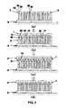
- the mold 8 has a plurality of raised supporters 80 on one side. According to the step shown in FIG. 2 (a) , each heat-dissipation plate 30 on the fin assembly 3 attaches to a wide side of the corresponding supporters 80 on the mold 8.
- each first protrusion 10 on the first heat conductive plate 1 fronts straight the top of corresponding supporter 80 on the mold 8.
- Each separate heat-dissipation plate 30 on the fin assembly 3 attaches to a wide side of the corresponding first protrusion 10.
- each second protrusion 21 on the second heat conductive plate 2 meets separately the corresponding passageway 12 on the first heat conductive plate 1.
- Using a punching machine punches the second heat conductive plate 2 for tightly closing the first heat conductive plate and the second heat conductive plate together, so as to complete the heat sink.
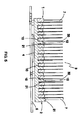
- FIG. 4 and FIG. 5 presenting the arrangement of the heat sink and its utilization with a circuit board 5, wherein the first heat conductive plate 1 and the second heat conductive plate 2 tightly close together; the second protrusions 21 wedge in the passageways 12 on the first conductive plate separately and therefore Interlace with the first protrusions 10; and the heat-dissipation plates 30 of the fin assembly 3 stand on the first heat conductive plate 1 and the second heat conductive plate 2, and part of each separate heat-dissipation plates 30 is sandwiched tightly between interlaced the first protrusion 10 and the second protrusion 21.
- the waste heat will conduct from bottom of the second heat conductive plates 2 to the second protrusions 21 and to the first protrusions 10 on the first conductive plate 1, so as to make each heat-dissipation plate 30, which is sandwiched between a pair of the first protrusion 10 and the second protrusion 21, can absorb and dissipate the waste heat from every pair of the first protrusion 10 and the second protrusion 21.
- CPU central processing unit
- each pair of the first protrusion 10 and the second protrusion 21 contacts the sandwiched heat-dissipation plate 30 with large area, the heat-dissipation efficiency is quite excellent by using the method of making a heat sink In accordance with the present invention.
- a chamfer 210 is formed along each of two relative long sides on the top of the second protrusion 21. Therefore, during the punch procedure above-mentioned, the second protrusion 21 can wedge in the passageway 12 on the first heat conductive plate 1 more smoothly.
- the other first heat conductive plate 1a resembles the first heat conductive plate 1 above-mentioned, but differs in a V-shape passageway 100 which is formed in each of the first protrusion 10a.
- the length of V-shape passageway 100 is same to the length of the first protrusion 10a. and the depth of V-shape passageway 100 is close to the bottom of the first protrusion 10a. For the reason, the V-shape passageway 100 divides the first protrusion 10a into two branches 101.
- a chamfer 102 is formed along each of two relative long sides on the bottom of the first protrusion 10a., and two branches 101 on each the first protrusion 10a lean outward slightly.
- the other second heat conductive plate 2a resembles the second heat conductive plate 2 above-mentioned, but differs in that each second protrusion 21a is asked to gradually narrow down from the bottom to the top slightly.
- FIG. 10 the arrangement of the first heat conductive 1a, the second heat conductive 2a and fin assembly 3 being put on the mold 8; wherein the procedures are same to FIG. 2 (a) ⁇ FIG. 2 (c ).
- the heat sink is assembled with the first heat conductive plate 1a, the second heat conductive plate 2a, and the fin assembly 3; wherein by using punch press above-mentioned for assembling the heat sink, and the procedure is same to FIG. 2 (d) .
- the second protrusion 21a separately wedges in the passageways 12a, each of two branches 101 on the first protrusion 10a will be pushed inwards to become straight by wedging the corresponding second protrusion 21a.
- the first heat conductive plate 1a and the second heat conductive plate can not only close together tightly but also smooth away the tolerance occurring during manufacturing, which finally enables both the first heat conductive 1a and the second heat conductive 2a close together tightly and enables each heat-dissipation plate of fin assembly 30 to be sandwiched between every pair of the second protrusion 21a and the first protrusion 10a tightly.
Landscapes
- Engineering & Computer Science (AREA)
- Physics & Mathematics (AREA)
- Theoretical Computer Science (AREA)
- Thermal Sciences (AREA)
- Microelectronics & Electronic Packaging (AREA)
- Human Computer Interaction (AREA)
- General Engineering & Computer Science (AREA)
- General Physics & Mathematics (AREA)
- Cooling Or The Like Of Electrical Apparatus (AREA)
- Cooling Or The Like Of Semiconductors Or Solid State Devices (AREA)
Abstract
Description
- The present invention generally relates to the method of making a heat sink, and more particular, relates to the procedure for assembling a fin assembly to a heat conductive plate.
- The conventional heat sink is assembled with metalwork of a fin assembly and heat conductive plates basically. Solder paste or heat conduction glue was used to stick them together.
- According to Taiwan patent no.
M337724 - The heat sink or heat-dissipation module above-mentioned still needs the soldering operation, and also needs screwing operation for closing tightly, which is time-consuming and work-requiring and still needs to be improved.
- Further scope of applicability of the present invention will become apparent from the detailed description given hereinafter. However, it should be understood that the detailed description and specific examples, while indicating preferred embodiments of the Invention, are given by way of illustration only, since various changes and modifications within the spirit and scope of the invention will become apparent to those skilled in the art from this detailed description.
- The present invention will become more fully understood from the detailed description given hereinbelow and the accompanying drawings which are given by way of illustration only, and thus are not limitative of the present invention, and wherein:
-
FIG. 1 is a breakdown perspective view in accordance with a preferred embodiment of the present invention; -
FIG. 2 is a schematic diagram of assembling process in accordance with a preferred embodiment of the present invention; -
FIG. 3 is a partial view of section of the first heat conductive plate in accordance with a preferred embodiment of the present invention; -
FIG. 4 is a perspective view of assembly circuit board in accordance with a preferred embodiment of the present invention; -
FIG. 5 is a A-A section view derived fromFIG. 3 ; -
FIG. 6 is a perspective view of the second heat conductive plate in accordance with a preferred embodiment of the present invention; -
FIG. 7 is a perspective view of another first heat conductive plate in the present invention; -
FIG. 8 is a partial detail view of another second heat conductive plate; -
FIG. 9 is a partial detail view of another second heat conductive plate in accordance with an embodiment with the present invention; -
FIG. 10 is a schematic diagram of assembly of another first heat conductive plate and the other second conductive plate; -
FIG. 11 is a partial view of section of assembly of the other first heat conductive plate and another second conductive plate. - The present invention will now be described in detail with reference to the accompanying drawings, wherein the same reference numerals will be used to identify the same or similar elements throughout the several views. It should be noted that the drawings should be viewed in the direction of orientation of the reference numerals.
- Referring to
FIG. 1 andFIG. 2 , an embodiment of the present invention, wherein the method comprising steps below: - Referring to
FIG. 1 , providing a first heatconductive plate 1; - Referring to
FIG. 1 , providing a second heatconductive plate 2; - Referring to
FIG. 1 , providing a fin assembly 3; - Referring to
FIG. 2 (b) , stacking the first heatconductive plate 1 onto the fin assembly 3; - Referring to
FIG. 2(c) , stacking the second heat conductive 2 onto the first heat conductive 1; and - Punching the first heat
conductive plate 1 and the second heatconductive plate 2 make them close tightly together. - For the time being, fulfill the task of assembling the first heat conductive plate, the second heat conductive plate and fin assembly into a heat sink. In the steps above-mentioned, no need of soldering or screwing, comparing with conventional technology, obviously have the advantage of timesaving, laborsaving, and low-cost.
- The above-mentioned procedure, due to the speedy assembling needs usually need an appropriate mold and punch press.
- For this reason, before the step above-mentioned of stacking the first heat
conductive plate 1 onto the fin assembly 3, according toFIG. 2 (a) , it would be best to provide a mold 8, and put the fin assembly 3 on the mold 8. - In order to accomplish the method of above-mentioned invention, the method of punching can achieve the purpose to assemble heat sink speedily. The structures of the first heat
conductive plate 1, the secondconductive plate 2, and the fin assembly 3 need to cooperate with each other. The manufacturing procedure for how they stack up will illustrate afterward. - Referring
FIG. 1 andFIG. 3 . the first heatconductive plate 1 has a plurality offirst protrusions 10 on the same side and a plurality ofpassageways 12 interlaced. The structure of middle section of thepassageways 12 are all hollow-through, except two side parts. The second heatconductive plate 2 has a plurality ofsecond protrusions 21 on the same side, which size and position are exactly fit for wedging thepassageways 12. The fin assembly 3 has a plurality of heat-dissipation plates. Each component above-mantioned can choose from the same or different heat conduction material, such as aluminum or copper. It would be beat to use all same material, like aluminum, for the convenience of manufacture. And furthermore, the first heatconductive plate 1 and the second heatconductive plate 2 can be electroplated in different color or can be printed with different color or patterns.. - The mold 8 has a plurality of raised
supporters 80 on one side. According to the step shown inFIG. 2 (a) , each heat-dissipation plate 30 on the fin assembly 3 attaches to a wide side of thecorresponding supporters 80 on the mold 8. - According to the step shown in
FIG.2 (b) , the top of eachfirst protrusion 10 on the first heatconductive plate 1 fronts straight the top ofcorresponding supporter 80 on the mold 8. Each separate heat-dissipation plate 30 on the fin assembly 3 attaches to a wide side of the correspondingfirst protrusion 10. - According to the step shown in
FIG. 2 (c) , eachsecond protrusion 21 on the second heatconductive plate 2 meets separately thecorresponding passageway 12 on the first heatconductive plate 1. - Using a punching machine punches the second heat
conductive plate 2 for tightly closing the first heat conductive plate and the second heat conductive plate together, so as to complete the heat sink. - Referring to
FIG. 4 andFIG. 5 , presenting the arrangement of the heat sink and its utilization with a circuit board 5, wherein the first heatconductive plate 1 and the second heatconductive plate 2 tightly close together; thesecond protrusions 21 wedge in thepassageways 12 on the first conductive plate separately and therefore Interlace with thefirst protrusions 10; and the heat-dissipation plates 30 of the fin assembly 3 stand on the first heatconductive plate 1 and the second heatconductive plate 2, and part of each separate heat-dissipation plates 30 is sandwiched tightly between interlaced thefirst protrusion 10 and thesecond protrusion 21. Wherein there are a backboard 6 and twobaffle plates 7 to make the frame around the fin assembly 3. - When the element 4, like a central processing unit (CPU), on the circuit board 5 works to cause waste heat, the waste heat will conduct from bottom of the second heat
conductive plates 2 to thesecond protrusions 21 and to thefirst protrusions 10 on the firstconductive plate 1, so as to make each heat-dissipation plate 30, which is sandwiched between a pair of thefirst protrusion 10 and thesecond protrusion 21, can absorb and dissipate the waste heat from every pair of thefirst protrusion 10 and thesecond protrusion 21. - Because each pair of the
first protrusion 10 and thesecond protrusion 21 contacts the sandwiched heat-dissipation plate 30 with large area, the heat-dissipation efficiency is quite excellent by using the method of making a heat sink In accordance with the present invention. - Referring to
FIG. 6 , achamfer 210 is formed along each of two relative long sides on the top of thesecond protrusion 21. Therefore, during the punch procedure above-mentioned, thesecond protrusion 21 can wedge in thepassageway 12 on the first heatconductive plate 1 more smoothly. - Referring to
FIG. 7 , the other first heatconductive plate 1a resembles the first heatconductive plate 1 above-mentioned, but differs in a V-shape passageway 100 which is formed in each of thefirst protrusion 10a. The length of V-shape passageway 100 is same to the length of the first protrusion 10a. and the depth of V-shape passageway 100 is close to the bottom of thefirst protrusion 10a. For the reason, the V-shape passageway 100 divides thefirst protrusion 10a into twobranches 101. - Referring to
FIG. 8 , achamfer 102 is formed along each of two relative long sides on the bottom of the first protrusion 10a., and twobranches 101 on each thefirst protrusion 10a lean outward slightly. - Referring to
FIG. 9 , the other second heat conductive plate 2a resembles the second heatconductive plate 2 above-mentioned, but differs in that eachsecond protrusion 21a is asked to gradually narrow down from the bottom to the top slightly. - Referring to
FIG. 10 , the arrangement of the first heat conductive 1a, the second heat conductive 2a and fin assembly 3 being put on the mold 8; wherein the procedures are same toFIG. 2 (a)∼ FIG. 2 (c ). - Referring to
FIG. 11 , the heat sink is assembled with the first heatconductive plate 1a, the second heat conductive plate 2a, and the fin assembly 3; wherein by using punch press above-mentioned for assembling the heat sink, and the procedure is same toFIG. 2 (d) . What needs to be pointed out is when thesecond protrusion 21a separately wedges in the passageways 12a, each of twobranches 101 on thefirst protrusion 10a will be pushed inwards to become straight by wedging the correspondingsecond protrusion 21a. - With the design of the first heat
conductive plate 1a and the second heat conductive plate abova-mentioned, the first heatconductive plate 1a and the second heat conductive 2a can not only close together tightly but also smooth away the tolerance occurring during manufacturing, which finally enables both the first heat conductive 1a and the second heat conductive 2a close together tightly and enables each heat-dissipation plate offin assembly 30 to be sandwiched between every pair of thesecond protrusion 21a and thefirst protrusion 10a tightly. - While the invention has been described by way of example and in terms of the preferred embodiment, it is to be understood that the invention is not limited to the disclosed embodiments, and it will be obvious that the same may be varied in many ways. Such variations are not to be regarded as a departure from the spirit and scope of the invention, and all such modifications as would be obvious to one skilled in the art are intended to be included within the scope of the following clams.
Claims (6)
- A method of making a heat sink, comprising:providing a first heat conductive plate, having a plurality of first protrusions placed on the same side and a plurality of passageways interlaced with said first protrusions;providing a second heat conductive plate, having a plurality of second protrusions placed on the same side and the size and position of said second protrusions is exactly fit for wedging said passageways in;providing a fin assembly, having a plurality of heat-dissipation plates;stacking said first heat conductive plate on said fin assembly, and making each heat-dissipation plate of said fin assembly attaches to a wide surface of said corresponding first protrusion on said first heat conductive plate;stacking said second heat conductive plate on said first heat conductive plate, and making each said second protrusion on said second heat conductive plate separately meet corresponding passageway on said first heat conductive plate: andpunching said first heat conductive plate and said second heat conductive plate to make them tightly stacked up and make each heat-dissipation plate of said fin assembly be partly sandwiched in between each pair of interlaced said first protrusion and said second protrusion,
- The method as claimed in claim 1, wherein comprise:forming a chamfer along each of the two relative long sides on the top of said second protrusion.
- The method as claimed in claim 1, wherein comprise:forming a V-shape passageway in each said first protrusion for dividing each said first protrusion into two branches, and said two branches leaning outward slightly.
- The method as claimed In claim 3, wherein comprise:forming a chamfer along each of the two relative long sides on the bottom of said first protrusion.
- The method as claimed in claim 4, wherein comprise making the width of each said second protrusion gradually narrows down from the bottom to the top slightly, and forming a chamfer along each of two relative long sides on the top of said second protrusion.
- The method as claimed in claim 1 to 5, wherein comprise:providing a mold; putting said fin assembly on said mold first; putting said first heat conductive plate on said mold; and wherein there is a plurality of raised supporters on a side of said mold, the top of each said first protrusion on said first heat conductive plate straightly meets to the top of said corresponding supporters, and each heat-dissipation plate of said fin assembly attaches to a long side of said corresponding supporter on said mold.
Applications Claiming Priority (1)
| Application Number | Priority Date | Filing Date | Title |
|---|---|---|---|
| TW098104258A TWI348017B (en) | 2009-02-10 | 2009-02-10 | Method of making a heat sink |
Publications (3)
| Publication Number | Publication Date |
|---|---|
| EP2216808A2 true EP2216808A2 (en) | 2010-08-11 |
| EP2216808A8 EP2216808A8 (en) | 2010-09-15 |
| EP2216808A3 EP2216808A3 (en) | 2015-11-18 |
Family
ID=42167249
Family Applications (1)
| Application Number | Title | Priority Date | Filing Date |
|---|---|---|---|
| EP09004891.9A Withdrawn EP2216808A3 (en) | 2009-02-10 | 2009-04-02 | Method of making a heat sink |
Country Status (4)
| Country | Link |
|---|---|
| EP (1) | EP2216808A3 (en) |
| JP (1) | JP4972664B2 (en) |
| KR (1) | KR101002369B1 (en) |
| TW (1) | TWI348017B (en) |
Families Citing this family (2)
| Publication number | Priority date | Publication date | Assignee | Title |
|---|---|---|---|---|
| CN103874391B (en) * | 2012-12-14 | 2016-12-21 | 技嘉科技股份有限公司 | Radiator and method of manufacturing the same |
| JP7269422B1 (en) * | 2022-07-26 | 2023-05-08 | 古河電気工業株式会社 | heat sink |
Family Cites Families (8)
| Publication number | Priority date | Publication date | Assignee | Title |
|---|---|---|---|---|
| DE3518310A1 (en) * | 1985-05-22 | 1986-11-27 | Aluminium-Walzwerke Singen Gmbh, 7700 Singen | REFRIGERATOR BODY FOR SEMICONDUCTOR COMPONENTS AND METHOD FOR THE PRODUCTION THEREOF |
| US6009938A (en) * | 1997-12-11 | 2000-01-04 | Eastman Kodak Company | Extruded, tiered high fin density heat sinks and method of manufacture |
| JP3273505B2 (en) * | 1999-08-18 | 2002-04-08 | 古河電気工業株式会社 | Heat sink provided with heat radiation fins and method of fixing heat radiation fins |
| JP2001110958A (en) | 1999-10-13 | 2001-04-20 | Mizutani Denki Kogyo Kk | Heat sink for electronic component |
| JP2004022830A (en) * | 2002-06-17 | 2004-01-22 | Fujikura Ltd | heatsink |
| JP4337441B2 (en) | 2003-07-30 | 2009-09-30 | 日本軽金属株式会社 | Heat dissipation member, method for manufacturing the same, and heat sink |
| JP2007165481A (en) * | 2005-12-12 | 2007-06-28 | Seiko Epson Corp | Heat exchanger, light source device, projector, electronic equipment |
| FR2898668B1 (en) * | 2006-03-15 | 2008-06-27 | Ferraz Date Ind Soc Par Action | HEAT EXCHANGER FOR COOLING AN ELECTRONIC COMPONENT AND METHOD FOR MANUFACTURING THE SAME |
-
2009
- 2009-02-10 TW TW098104258A patent/TWI348017B/en active
- 2009-03-19 JP JP2009068119A patent/JP4972664B2/en active Active
- 2009-04-02 EP EP09004891.9A patent/EP2216808A3/en not_active Withdrawn
- 2009-05-06 KR KR1020090039094A patent/KR101002369B1/en active Active
Also Published As
| Publication number | Publication date |
|---|---|
| EP2216808A8 (en) | 2010-09-15 |
| EP2216808A3 (en) | 2015-11-18 |
| KR20100091868A (en) | 2010-08-19 |
| KR101002369B1 (en) | 2010-12-17 |
| JP2010186976A (en) | 2010-08-26 |
| JP4972664B2 (en) | 2012-07-11 |
| TW201030304A (en) | 2010-08-16 |
| TWI348017B (en) | 2011-09-01 |
Similar Documents
| Publication | Publication Date | Title |
|---|---|---|
| CN207489855U (en) | Radiator | |
| EP3333530B1 (en) | Parallel heat-pipes type heat sink and manufacturing method thereof | |
| WO2017021130A1 (en) | Heat sink lighting device and method for manufacturing a heat sink | |
| US20130118717A1 (en) | Heat-dissipating device and method for fabricating the same | |
| CN105873415A (en) | Base and heat pipe combination of radiator | |
| US8296947B2 (en) | Heat sink and method of manufacturing the same | |
| US20050000682A1 (en) | Heat dissipating fins of heat sink and manufacturing method thereof | |
| US20130105132A1 (en) | Heat sink fin and heat sink device | |
| US20150330716A1 (en) | Base plate fixing structure for a heat dissipating module | |
| US9138840B2 (en) | Method for manufacturing a heat sink | |
| US20020043359A1 (en) | Heat sink for electronic parts and manufacture thereof | |
| CN101829741B (en) | Manufacturing method of heat sink | |
| EP2216807A2 (en) | Heat-dissipation apparatus | |
| CN103889189B (en) | Heat sink assembly structure | |
| US20110094723A1 (en) | Combination of fastener and thermal-conducting member | |
| CN103369918B (en) | Heat radiation device and assembling method thereof | |
| JP5927707B2 (en) | heatsink | |
| KR101321190B1 (en) | Folded frame carrier for mosfet bga | |
| US20120160467A1 (en) | Heat sink and assembly method thereof | |
| JP6324479B1 (en) | Metal board for circuit board, circuit board, power module, metal plate molded product, and method for manufacturing circuit board | |
| JP4972664B2 (en) | Manufacturing method of heat dissipation device | |
| CN107851642A (en) | Crimp type semiconductor devices stacks | |
| US10973153B2 (en) | Power module | |
| EP2299229B1 (en) | Plurality of heat pipes and fixing assembly therefor, and heat sink | |
| US20120120606A1 (en) | Printed circuit board with heat sink |
Legal Events
| Date | Code | Title | Description |
|---|---|---|---|
| PUAI | Public reference made under article 153(3) epc to a published international application that has entered the european phase |
Free format text: ORIGINAL CODE: 0009012 |
|
| AK | Designated contracting states |
Kind code of ref document: A2 Designated state(s): AT BE BG CH CY CZ DE DK EE ES FI FR GB GR HR HU IE IS IT LI LT LU LV MC MK MT NL NO PL PT RO SE SI SK TR |
|
| AX | Request for extension of the european patent |
Extension state: AL BA RS |
|
| RIN1 | Information on inventor provided before grant (corrected) |
Inventor name: MAO, TAI-CHUAN Inventor name: HUANG, SHUN-CHIH |
|
| RAP1 | Party data changed (applicant data changed or rights of an application transferred) |
Owner name: GIGA-BYTE TECHNOLOGY CO., LTD. |
|
| PUAL | Search report despatched |
Free format text: ORIGINAL CODE: 0009013 |
|
| AK | Designated contracting states |
Kind code of ref document: A3 Designated state(s): AT BE BG CH CY CZ DE DK EE ES FI FR GB GR HR HU IE IS IT LI LT LU LV MC MK MT NL NO PL PT RO SE SI SK TR |
|
| AX | Request for extension of the european patent |
Extension state: AL BA RS |
|
| RIC1 | Information provided on ipc code assigned before grant |
Ipc: H01L 21/48 20060101AFI20151009BHEP |
|
| STAA | Information on the status of an ep patent application or granted ep patent |
Free format text: STATUS: THE APPLICATION HAS BEEN WITHDRAWN |
|
| 18W | Application withdrawn |
Effective date: 20160512 |