EP2216734B1 - Targeting system for a portable image reader - Google Patents
Targeting system for a portable image reader Download PDFInfo
- Publication number
- EP2216734B1 EP2216734B1 EP10154305.6A EP10154305A EP2216734B1 EP 2216734 B1 EP2216734 B1 EP 2216734B1 EP 10154305 A EP10154305 A EP 10154305A EP 2216734 B1 EP2216734 B1 EP 2216734B1
- Authority
- EP
- European Patent Office
- Prior art keywords
- target
- targeting
- components
- pattern
- light
- Prior art date
- Legal status (The legal status is an assumption and is not a legal conclusion. Google has not performed a legal analysis and makes no representation as to the accuracy of the status listed.)
- Expired - Lifetime
Links
Images





Classifications
-
- G—PHYSICS
- G06—COMPUTING OR CALCULATING; COUNTING
- G06K—GRAPHICAL DATA READING; PRESENTATION OF DATA; RECORD CARRIERS; HANDLING RECORD CARRIERS
- G06K7/00—Methods or arrangements for sensing record carriers, e.g. for reading patterns
- G06K7/10—Methods or arrangements for sensing record carriers, e.g. for reading patterns by electromagnetic radiation, e.g. optical sensing; by corpuscular radiation
- G06K7/10544—Methods or arrangements for sensing record carriers, e.g. for reading patterns by electromagnetic radiation, e.g. optical sensing; by corpuscular radiation by scanning of the records by radiation in the optical part of the electromagnetic spectrum
-
- G—PHYSICS
- G06—COMPUTING OR CALCULATING; COUNTING
- G06K—GRAPHICAL DATA READING; PRESENTATION OF DATA; RECORD CARRIERS; HANDLING RECORD CARRIERS
- G06K2207/00—Other aspects
- G06K2207/1011—Aiming
Definitions
- the present invention relates to the field of portable image capture devices, and more specifically, to a targeting system for a portable image reader.
- Image reading devices of the type that allow optimal imaging distances include a targeting scheme of some kind useful solely in aligning the image reader to the target, to obtain an optimal imaging distance from the target. Most of these techniques project a pattern onto the target from a targeting LED or laser diode. An aperture and IR light shaping optics are often used to project a pattern onto the target as an aid to the human operator to correctly position the image reader based on the targeting pattern.
- the operator moves the image reader until targeting lines or dots converge at a predefined point, which relates to the point at which an acceptable image can be acquired.
- An acceptable image may be defined as one that contains sufficient resolution for post-processing.
- US Patent 6,385,352 which issued to Roustaei on May 7th 2002 , details a technique whereby a cylindrical lens is positioned over the targeting LED's to project a vertical line to frame the target. This technique however does not disclose apparatus for shaping the light emitted from the targeting LED's or for compensating for the resulting growth caused by the magnification of the line as the image reader is moved too close, or the shrinking of the line as it is moved away.
- U.S. patent application Publication 2003/0019934 which was filed by Hunter on March 7th 2002 and published on January 30th 2003, discloses a method using an aperture positioned over the targeting LEDs to project a line pattern onto the target. These lines however, are projected laterally (horizontally) and do not bound the target. With this technique, it would be difficult to intuit the direction to move the image reader, as the patterns simply form a line across the target. In an imaging solution, this technique is particularly unsuitable, as the human operator would have difficulty in aligning the centre of the target with the line pattern.
- US-B1-5689104 provides an optical code reader. A guide beam projector radiates a plurality of guide beams onto an article.
- the guide beams may mark four spots on the surface of an article placed in front of a read window of the optical code reader.
- EP-A-1172756 provides a coded information reader with a system for projecting at least two beam portions onto a reading area located in front of the coded information reader. The beam portions expand outwards from a central axis.
- a targeting system which provides an operator with intuitive information on which direction to move the portable image capturing device in order to achieve a successful decode. It would also be desirable for the targeting system to provide this intuitive information within the parameters of the entire imaging range of the device.
- the present invention provides a system for image sensing having the features of appended claim 1.
- the present invention provides a system for image sensing having the features of appended claim 2. Details of embodiments are provided in the dependent claims.
- the present invention is directed to an image reader comprising a circuit board, an image sensor mounted on the circuit board and an objective lens assembly having an objective lens axis positioned in front of the image sensor and adapted to direct light from a target to the image sensor.
- the image reader further includes a targeting system adapted to project a predetermined pattern having two or more components onto the target whereby the components maintain a uniform first distance between one another to bound the target and whereby components vary in size as a function of a second distance between the image reader and the target.
- the pattern components may be one or two pairs of substantially parallel lines, where the lines vary in length as a function of the distance between the reader and the target.
- the targeting system may comprise a first optical apparatus located adjacent to one side of the objective lens assembly and adapted to project one line onto the target and a second optical apparatus located adjacent to substantially the opposite side of the objective lens assembly adapted to project another line onto the target.
- the targeting system may comprise a first and a second optical apparati located in a first plane adjacent to opposite sides of the objective lens assembly and adapted to project two substantially parallel lines onto the target, and a third and a fourth optical apparati located in a second plane perpendicular to the first plane adjacent to opposite sides of the objective lens assembly and adapted to project two substantially parallel lines onto the target substantially perpendicular to the first and second optical apparatus parallel lines.
- each of the optical apparati includes a targeting illumination source, an aperture having an elongated slit positioned in front of the illumination source and a cylindrical lens positioned in a corresponding orientation in front of the aperture.
- the targeting illumination may be a light emitting diode.
- the elongated slits in the first and the second optical apparati are substantially perpendicular to a plane through the first and second optical apparati
- the elongated slits in the third and the fourth optical apparati are substantially perpendicular to a plane through the third and fourth optical apparati.
- a portable image reader comprises an image sensor, which could be linear or an array. Typically the sensor would be a CCD or CMOS image sensor, however other image sensors could also be used with the present invention.
- a typical reader further includes an objective lens mounted over the image sensor at a fixed distance to provide a specific focal length, an illumination source to illuminate a target to be imaged, a targeting light source and light shaping optics to direct a targeting pattern onto the target. The targeting pattern allows a human operator to align the image reader with the target.
- a predetermined pattern having two or more components is projected onto the target such that the components maintain a uniform distance from one another to bound the target and at the same time components vary in size as a function of their distance between the image reader and the target.
- the components are straight parallel lines and, when projected on the target, the ends of the lines form the corners of a substantially square shape, at which time, the operator knows that image acquisition may be successfully obtained.
- FIGS. 1A , 1B , 1C and 1D show an embodiment of the image reader module 5 in accordance with the present invention.
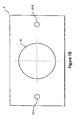
- Targeting LED's 20A and 20B are positioned adjacent to and on opposite sides of the object lens barrel 30 as illustrated in figure 1B , which shows the positioning of the targeting LED's 20A and 20B in relation to the objective lens 30.
- apertures 10A and 10B are positioned in front of the targeting LED's 20A and 20B, and cylindrical lenses 40A and 40B are positioned in front of the apertures 10A and 10B.
- the apertures 10A and 10B shape the light emitted from the targeting LED's into substantially rectangular vertical lines 50 and 60, which have a substantially constant width as seen in figure 1A .
- the cylindrical lenses 40A and 40B transmit these vertical line patterns 50 and 60 onto the imaging target 70.
- apertures 10A and 10B may be used without departing from the scope of the invention. Additional apertures may be added between apertures 10A and 10B and the cylindrical lenses 40A and 40B. These additional apertures would be aligned with apertures 40A and 40B and may be used to further shape the emitted light from the targeting LED's 20A and 20B.
- FIG. 1C Components of the image reader module 5 are shown in figure 1C , these include a circuit board 12 on which is mounted an image sensor array 14, LED's 20A, 20B and apertures 10A, 10B.
- An illumination board 16 is configured with openings 18A and 18B over each LED 20A, 20B, aperture 10A, 10B combination. These openings 18A and 18B may be configured as slit apertures to further shape the emitted light or they may simply allow the light to pass unobstructed to the cylindrical lenses 40A and 40B. It should however, be noted by those skilled in the art that this is one possible configuration of an image reader module and other configurations, having more or less boards and/or panels are possible without departing from the scope of the invention.
- the shaped light emitted from the targeting LED 20B forms a long, but narrow line on the target 70.
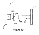
- This side view of the image reader 5 shows how the light pattern or line 60 increases in length slightly in the vertical direction as the module is moved away from the target 70. The relevance of this variation in length will be explained in further detail below.
- the aperture of the preferred embodiment is a slit aperture 10B.
- the light from the targeting LED 20B passes through the slit aperture 10B to a cylindrical lens 40B.
- the cylindrical lens 40B is positioned over the aperture 10B in a corresponding vertical orientation.
- the substantially rectangular shaped aperture opening 15B shapes the light emitted from the targeting LED 20B.
- the resulting pattern of at least two vertical lines 50 and 60 are projected onto the target area 70.
- the projected lines 50 and 60 Due to the positioning and vertical orientation of the cylindrical lenses 40A and 40B over the vertical apertures 10A and 10B, the projected lines 50 and 60, as they appear on the target, remain at a substantially constant distance apart from one another regardless of the distance of the module from the target.
- the distance may be 10-20 mm for bar code symbology readers or may be set for what best suits the user's requirements.
- the lines become longer or shorter.
- the lengths of the vertical lines 50 and 60 are dependent on the device proximity to the target. A human operator can easily align the image reader 5 such that the ends of the two vertical lines 50 and 60 form the corners of a square shape at or near the centre of the target 70.
- the lines are of substantially equal length and of the same length as the distance between them.
- Figure 3A shows the resulting pattern when the image reader 5 is too close to the target 70 to obtain a successful image acquisition.
- the lines 50 and 60 appear to be shorter than the distance between them. The operator would intuitively realize that the image reader 5 is too close to the target and will move it away from the target 70 resulting in a lengthening of the lines 50 and 60.
- Figure 3C shows the resulting line patterns 50 and 60 when the image reader 5 is past an optimal distance to obtain a successful image acquisition.
- the vertical lines 50 and 60 appear longer than the distance between them. The operator would intuitively realize that the image reader 5 is too far from the target 70 and will move the device closer to the target 70 resulting in a shortening of the lines 50 and 60.
- Figure 3B represents the line patterns 50 and 60 resulting when an optimal distance, device to target, is achieved. It is not necessary for the line patterns 50 and 60 to line up perfectly with the centre of the target 70 or for the line patterns to be exactly the same length as the distance between them, in order to obtain a successful image acquire. It is only necessary for the pattern to be projected onto the target 70 and for the pattern to form a substantially square shape. In this way, a range of optimal targeting distances is possible. It is to be noted that the distance between the parallel lines 50, 60 is the same in all of the figures 3A to 3C regardless of the distance between the reader and the target.
- the targeting LED's would be position adjacent to, above and below the objective lens assembly with corresponding apertures and cylindrical lenses positioned on a horizontal plane.
- an apparatus that forms a square pattern at or near the centre of the target, either vertically or horizontally, in order to provide interpretive information to the human operator as to which direction to move the image reader.
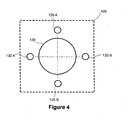
- An image reader module 105 includes first targeting LED's 120A and 120B positioned adjacent to and on both sides of the objective lens 130 and second targeting LED's 125A and 125B positioned adjacent to, above and below the objective lens 130. With this arrangement, the targeting LED's form a substantially square pattern around the objective lens 130. Vertically oriented apertures are positioned over the first LED's 120A and 120B and horizontally oriented apertures are positioned over the second LED's 125A and 125B. Cylindrical lenses are positioned over each of the apertures in a corresponding orientation.
- line patterns 150, 155, 160 and 165 are projected onto the target 170, forming a square box shape on the target 170.
- the vertical lines 150, 160 maintain a uniform distance apart but vary in length in the vertical direction as the reader 105 is moved towards or away from the target 170.
- the horizontally projected lines 155, 165 also remain at a constant width apart and vary in length in the horizontal direction as the reader 105 is moved towards or away from the target 170.
- the length of the lines 150, 155, 160, 165 are dependent on the image reader 105 proximity and angle to the target 170.
- Figure 5B shows the resulting vertical and horizontal line patterns 150, 155, 160 and 165, when the image reader 105 is at an optimal distance from the target 170, but is rotated counter clockwise about the objective lens axis causing the target 170 to not be optimally located relative to the center of the field of view of the image reader 105.
- the lines 150, 155, 160 and 165 are evenly spaced, but the pattern forms a rotated box shape on the target 170. Again the human operator would intuitively know which direction to move the image reader 105 in order to align the pattern lines 150, 155, 160 and 165 with the target 170.
- an operator can determine not only the optimal imaging range, but also if the device is being held at an acceptable angle in relation to the target.
- This targeting system allows a human operator to quickly position a portable imaging device, such as a barcode reader, over a target.
- the range over which an acceptable image can be acquired with a standard image reader is approximately 15 to 20 cm. Since the targeting pattern of the present invention forms a square shaped pattern when an operator moves the image reader to within an optimal range, and does not require that the operator align dots or line patterns to converge at a specific distance from the target, the present invention advantageously permits the operator greater latitude to move the image reader to any point within this range of distances, and still obtain an acceptable image of the target. Once the operator finds a pattern shape that works well under difficult circumstances, they can quickly and intuitively adjust the scanner to produce the known pattern shape.
- the targeting pattern of the present invention forms a substantially square shape in order to obtain a successful image acquisition. Aspect ratio of the viewed pattern intuitively tells the operator what direction he must move the reader to better position it at the optimal working distance from the target. In the second embodiment of the present invention, this feedback comes from the spacing at the corners of the targeting pattern where the length of the pattern bars is equal to the distance between the bars.
- the present invention provides a targeting system in an image reader that provides an operator with intuitive information to aim and align the image reader relative to the target, in order to achieve a successful decode.
- the intuitive targeting system may operate within the parameters of the entire imaging range of the image reader, that is, the entire range of distances in which a successful decode is possible and the targeting system may identify the center of the field of view. Further, the targeting system may be constructed at low cost with only slight modifications to existing image reader construction techniques.
Landscapes
- Physics & Mathematics (AREA)
- Engineering & Computer Science (AREA)
- Electromagnetism (AREA)
- General Physics & Mathematics (AREA)
- Toxicology (AREA)
- General Health & Medical Sciences (AREA)
- Artificial Intelligence (AREA)
- Computer Vision & Pattern Recognition (AREA)
- Health & Medical Sciences (AREA)
- Theoretical Computer Science (AREA)
- Image Input (AREA)
- Facsimile Scanning Arrangements (AREA)
- Studio Devices (AREA)
- Closed-Circuit Television Systems (AREA)
- Aiming, Guidance, Guns With A Light Source, Armor, Camouflage, And Targets (AREA)
- Apparatus For Radiation Diagnosis (AREA)
Abstract
Description
- The present invention relates to the field of portable image capture devices, and more specifically, to a targeting system for a portable image reader.
- Image reading devices of the type that allow optimal imaging distances, include a targeting scheme of some kind useful solely in aligning the image reader to the target, to obtain an optimal imaging distance from the target. Most of these techniques project a pattern onto the target from a targeting LED or laser diode. An aperture and IR light shaping optics are often used to project a pattern onto the target as an aid to the human operator to correctly position the image reader based on the targeting pattern.
- The operator moves the image reader until targeting lines or dots converge at a predefined point, which relates to the point at which an acceptable image can be acquired. An acceptable image may be defined as one that contains sufficient resolution for post-processing. With this method, if the initial operating position is not correct it may be difficult for the operator to determine which direction the device must be moved in order to get into range. Further, with this method, the operator will perceive they can only capture an image at the predetermined distance at which the lines or dots converge, even though an acceptable image could potentially be acquired some distance before or beyond that point.
-
US Patent 6,385,352, which issued to Roustaei on May 7th 2002 , details a technique whereby a cylindrical lens is positioned over the targeting LED's to project a vertical line to frame the target. This technique however does not disclose apparatus for shaping the light emitted from the targeting LED's or for compensating for the resulting growth caused by the magnification of the line as the image reader is moved too close, or the shrinking of the line as it is moved away. -
U.S. patent application Publication 2003/0019934, which was filed by Hunter on March 7th 2002 and published on January 30th 2003, discloses a method using an aperture positioned over the targeting LEDs to project a line pattern onto the target. These lines however, are projected laterally (horizontally) and do not bound the target. With this technique, it would be difficult to intuit the direction to move the image reader, as the patterns simply form a line across the target. In an imaging solution, this technique is particularly unsuitable, as the human operator would have difficulty in aligning the centre of the target with the line pattern.US-B1-5689104 provides an optical code reader. A guide beam projector radiates a plurality of guide beams onto an article. The guide beams may mark four spots on the surface of an article placed in front of a read window of the optical code reader.EP-A-1172756 provides a coded information reader with a system for projecting at least two beam portions onto a reading area located in front of the coded information reader. The beam portions expand outwards from a central axis. - Therefore there is a need for a targeting system, which provides an operator with intuitive information on which direction to move the portable image capturing device in order to achieve a successful decode. It would also be desirable for the targeting system to provide this intuitive information within the parameters of the entire imaging range of the device.
- In accordance with a first aspect, the present invention provides a system for image sensing having the features of appended claim 1. In accordance with a second aspect, the present invention provides a system for image sensing having the features of appended claim 2. Details of embodiments are provided in the dependent claims.
- The present invention is directed to an image reader comprising a circuit board, an image sensor mounted on the circuit board and an objective lens assembly having an objective lens axis positioned in front of the image sensor and adapted to direct light from a target to the image sensor. The image reader further includes a targeting system adapted to project a predetermined pattern having two or more components onto the target whereby the components maintain a uniform first distance between one another to bound the target and whereby components vary in size as a function of a second distance between the image reader and the target.
- In accordance with another aspect of this invention, the pattern components may be one or two pairs of substantially parallel lines, where the lines vary in length as a function of the distance between the reader and the target.
- In accordance with a further aspect of the invention, the targeting system may comprise a first optical apparatus located adjacent to one side of the objective lens assembly and adapted to project one line onto the target and a second optical apparatus located adjacent to substantially the opposite side of the objective lens assembly adapted to project another line onto the target.
- In accordance with yet another aspect of this invention, the targeting system may comprise a first and a second optical apparati located in a first plane adjacent to opposite sides of the objective lens assembly and adapted to project two substantially parallel lines onto the target, and a third and a fourth optical apparati located in a second plane perpendicular to the first plane adjacent to opposite sides of the objective lens assembly and adapted to project two substantially parallel lines onto the target substantially perpendicular to the first and second optical apparatus parallel lines.
- In accordance with a specific aspect of this invention, each of the optical apparati includes a targeting illumination source, an aperture having an elongated slit positioned in front of the illumination source and a cylindrical lens positioned in a corresponding orientation in front of the aperture. The targeting illumination may be a light emitting diode.
- In accordance with a further specific aspect of the invention, the elongated slits in the first and the second optical apparati are substantially perpendicular to a plane through the first and second optical apparati, and the elongated slits in the third and the fourth optical apparati are substantially perpendicular to a plane through the third and fourth optical apparati.
- Other aspects and advantages of the invention, as well as the structure and operation of various embodiments of the invention, will become apparent to those ordinarily skilled in the art upon review of the following description of the invention in conjunction with the accompanying drawings.
- The invention will be described with reference to the accompanying drawings, wherein:
-
Figure 1A is a top view of an image reader module in cross-section according to the present invention; -
Figure 1B is a front view of the image reader module infigure 1A illustrating the positioning of the targeting LED's, according to the present invention; -
Figure 1C is an exploded top view of the image reader module infigure 1A ; -
Figure 1D is a side view of the image reader module illustrated inFigure 1C ; -
Figure 2 is an exploded view representation of the cylindrical lens and slit aperture according to an embodiment of the present invention; -
Figure 3A through 3D illustrate a targeting pattern projected by the target system of the present invention at various module to target distances; -
Figure 4 is a front view of an image reader module according to another embodiment of the present invention including first and second targeting LED's; -
Figure 5A illustrates a targeting pattern projected by the target system according to the embodiment illustrated inFigure 4 ; and -
Figure 5B illustrates a misaligned targeting pattern projected by the target system according to the embodiment illustrated inFigure 4 . - For purposes of explanation, specific embodiments are set forth to provide a thorough understanding of the present invention. However, it will be understood by one skilled in the art, from reading this disclosure, that the invention may be practiced without these specific details. Moreover, well-known elements, devices, process steps and the like are not set forth in detail in order to avoid obscuring the scope of the invention described.
- A portable image reader comprises an image sensor, which could be linear or an array. Typically the sensor would be a CCD or CMOS image sensor, however other image sensors could also be used with the present invention. A typical reader further includes an objective lens mounted over the image sensor at a fixed distance to provide a specific focal length, an illumination source to illuminate a target to be imaged, a targeting light source and light shaping optics to direct a targeting pattern onto the target. The targeting pattern allows a human operator to align the image reader with the target.
- In the targeting system in accordance with the present invention, a predetermined pattern having two or more components is projected onto the target such that the components maintain a uniform distance from one another to bound the target and at the same time components vary in size as a function of their distance between the image reader and the target. In one embodiment, the components are straight parallel lines and, when projected on the target, the ends of the lines form the corners of a substantially square shape, at which time, the operator knows that image acquisition may be successfully obtained.
- The embodiments of the present invention will now be described in detail with reference to the drawings.
- The drawings of
figures 1A ,1B ,1C and1D show an embodiment of theimage reader module 5 in accordance with the present invention. Targeting LED's 20A and 20B, are positioned adjacent to and on opposite sides of theobject lens barrel 30 as illustrated infigure 1B , which shows the positioning of the targeting LED's 20A and 20B in relation to theobjective lens 30. In order to project the desired light pattern onto a target, apertures 10A and 10B are positioned in front of the targeting LED's 20A and 20B, and cylindrical lenses 40A and 40B are positioned in front of the apertures 10A and 10B. The apertures 10A and 10B shape the light emitted from the targeting LED's into substantially rectangularvertical lines figure 1A . The cylindrical lenses 40A and 40B transmit thesevertical line patterns imaging target 70. - It should be noted by those skilled in the art that more than one aperture may be used without departing from the scope of the invention. Additional apertures may be added between apertures 10A and 10B and the cylindrical lenses 40A and 40B. These additional apertures would be aligned with apertures 40A and 40B and may be used to further shape the emitted light from the targeting LED's 20A and 20B.
- Components of the
image reader module 5 are shown infigure 1C , these include acircuit board 12 on which is mounted animage sensor array 14, LED's 20A, 20B and apertures 10A, 10B. Anillumination board 16 is configured with openings 18A and 18B over each LED 20A, 20B, aperture 10A, 10B combination. These openings 18A and 18B may be configured as slit apertures to further shape the emitted light or they may simply allow the light to pass unobstructed to the cylindrical lenses 40A and 40B. It should however, be noted by those skilled in the art that this is one possible configuration of an image reader module and other configurations, having more or less boards and/or panels are possible without departing from the scope of the invention. - With reference to
Figure 1D , the shaped light emitted from the targeting LED 20B forms a long, but narrow line on thetarget 70. This side view of theimage reader 5 shows how the light pattern orline 60 increases in length slightly in the vertical direction as the module is moved away from thetarget 70. The relevance of this variation in length will be explained in further detail below. - The aperture of the preferred embodiment is a slit aperture 10B. In the exploded view of
Figure 2 , the light from the targeting LED 20B passes through the slit aperture 10B to a cylindrical lens 40B. The cylindrical lens 40B is positioned over the aperture 10B in a corresponding vertical orientation. The substantially rectangular shaped aperture opening 15B shapes the light emitted from the targeting LED 20B. Referring again toFigures 1A , and1D , the resulting pattern of at least twovertical lines target area 70. Due to the positioning and vertical orientation of the cylindrical lenses 40A and 40B over the vertical apertures 10A and 10B, the projectedlines vertical lines image reader 5 such that the ends of the twovertical lines target 70. At the optimal imaging distance, the lines are of substantially equal length and of the same length as the distance between them. -
Figure 3A shows the resulting pattern when theimage reader 5 is too close to thetarget 70 to obtain a successful image acquisition. Thelines image reader 5 is too close to the target and will move it away from thetarget 70 resulting in a lengthening of thelines -
Figure 3C shows the resultingline patterns image reader 5 is past an optimal distance to obtain a successful image acquisition. Thevertical lines image reader 5 is too far from thetarget 70 and will move the device closer to thetarget 70 resulting in a shortening of thelines - With reference to
Figure 3D , if theimage reader 5 is aligned laterally at a substantially less than perpendicular angle in relation to thetarget 70, thevertical lines image reader 5. -
Figure 3B represents theline patterns line patterns target 70 or for the line patterns to be exactly the same length as the distance between them, in order to obtain a successful image acquire. It is only necessary for the pattern to be projected onto thetarget 70 and for the pattern to form a substantially square shape. In this way, a range of optimal targeting distances is possible. It is to be noted that the distance between theparallel lines figures 3A to 3C regardless of the distance between the reader and the target. - While this invention has so far been described with reference to vertical line patterns, it should be noted by a person skilled in the art that at least two horizontal lines, spaced a constant length apart, but magnified in the horizontal direction, could also be used in place of the vertical line patterns of the above described embodiment without departing from the scope of the invention. In this case, the targeting LED's would be position adjacent to, above and below the objective lens assembly with corresponding apertures and cylindrical lenses positioned on a horizontal plane. Essentially, what is required in accordance with the present invention is an apparatus that forms a square pattern at or near the centre of the target, either vertically or horizontally, in order to provide interpretive information to the human operator as to which direction to move the image reader.
- The diagram of
Figure 4 shows another embodiment of the present invention. Animage reader module 105 includes first targeting LED's 120A and 120B positioned adjacent to and on both sides of theobjective lens 130 and second targeting LED's 125A and 125B positioned adjacent to, above and below theobjective lens 130. With this arrangement, the targeting LED's form a substantially square pattern around theobjective lens 130. Vertically oriented apertures are positioned over the first LED's 120A and 120B and horizontally oriented apertures are positioned over the second LED's 125A and 125B. Cylindrical lenses are positioned over each of the apertures in a corresponding orientation. - With reference to
Figure 5A it can be seen that with this embodiment, fourline patterns target 170, forming a square box shape on thetarget 170. Thevertical lines reader 105 is moved towards or away from thetarget 170. Similarly, due to the positioning and horizontal orientation of the cylindrical lenses 140 over the horizontal apertures, the horizontally projectedlines reader 105 is moved towards or away from thetarget 170. The length of thelines image reader 105 proximity and angle to thetarget 170. -
Figure 5B shows the resulting vertical andhorizontal line patterns image reader 105 is at an optimal distance from thetarget 170, but is rotated counter clockwise about the objective lens axis causing thetarget 170 to not be optimally located relative to the center of the field of view of theimage reader 105. Thelines target 170. Again the human operator would intuitively know which direction to move theimage reader 105 in order to align the pattern lines 150, 155, 160 and 165 with thetarget 170. - By using at least two vertical or two horizontal line patterns or a combination of horizontal and vertical line patterns, an operator can determine not only the optimal imaging range, but also if the device is being held at an acceptable angle in relation to the target.
- This targeting system allows a human operator to quickly position a portable imaging device, such as a barcode reader, over a target. The range over which an acceptable image can be acquired with a standard image reader is approximately 15 to 20 cm. Since the targeting pattern of the present invention forms a square shaped pattern when an operator moves the image reader to within an optimal range, and does not require that the operator align dots or line patterns to converge at a specific distance from the target, the present invention advantageously permits the operator greater latitude to move the image reader to any point within this range of distances, and still obtain an acceptable image of the target. Once the operator finds a pattern shape that works well under difficult circumstances, they can quickly and intuitively adjust the scanner to produce the known pattern shape.
- This technique is insensitive to absolute measurement. The operator simply looks for relative size changes. The targeting pattern of the present invention forms a substantially square shape in order to obtain a successful image acquisition. Aspect ratio of the viewed pattern intuitively tells the operator what direction he must move the reader to better position it at the optimal working distance from the target. In the second embodiment of the present invention, this feedback comes from the spacing at the corners of the targeting pattern where the length of the pattern bars is equal to the distance between the bars.
- From the above it is evident that the present invention has numerous advantages. The present invention provides a targeting system in an image reader that provides an operator with intuitive information to aim and align the image reader relative to the target, in order to achieve a successful decode. The intuitive targeting system may operate within the parameters of the entire imaging range of the image reader, that is, the entire range of distances in which a successful decode is possible and the targeting system may identify the center of the field of view. Further, the targeting system may be constructed at low cost with only slight modifications to existing image reader construction techniques.
- It should be noted by a person skilled in the art that this invention is not limited to a use with LED's. Other types of light sources, including light sources with different wavelengths, may be used without departing from the scope of the invention. It should also be noted that while this invention has been described using substantially square shaped targeting patterns, different shapes and combinations of patterns might also be used without departing from the scope of the invention.
- While the invention has been described according to what is presently considered to be the most practical and preferred embodiments, it must be understood that the invention is not limited to the disclosed embodiments. Those ordinarily skilled in the art will understand that various modifications and equivalent structures and functions may be made without departing from the scope of the invention as defined in the claims. Therefore, the invention as defined in the claims must be accorded the broadest possible interpretation so as to encompass all such modifications and equivalent structures and functions.
Claims (14)
- A system for image sensing comprising:a targeting system for projecting a pattern (50, 60,150, 155, 160, 165) having a pair of components to bound a target (70, 170), the targeting system being positioned relative to an objective lens (30, 130) assembly for directing light from the target (70, 170) to an image sensor (14), the targeting system including, for the components of the pattern (50, 60,150, 155, 160, 165):a plurality of targeting illumination sources (20A, 20B; 120A, 120B; 125A, 125B); anda light shaping device for shaping light from the plurality of the targeting illumination sources (20A, 20B; 120A, 120B; 125A, 125B), the light shaping device configured to maintain a substantially uniform first distance between the components of the pattern (50, 60,150, 155, 160), regardless of a second distance, within a range, between the targeting system and the target (70, 170) to bound the target (70, 170), the components of the pattern (50, 60,150, 155, 160, 165) varying in size as a function of the second distance between the targeting system and the target (70, 170).
- A system for image sensing comprising:a targeting system for projecting a pattern (50, 60,150, 155, 160, 165) having two or more pairs of components to bound a target (70, 170), the targeting system being positioned relative to an objective lens (30, 130) assembly for directing light from the target (70, 170) to an image sensor (14), the targeting system including, for the components of the pattern (50, 60,150, 155, 160, 165):a plurality of targeting illumination sources (20A, 20B; 120A, 120B; 125A, 125B); anda light shaping device for shaping light from the plurality of the targeting illumination sources (20A, 20B; 120A, 120B; 125A, 125B), the light shaping device configured to maintain a substantially uniform first distance between each pair of components of the pattern (50, 60,150, 155, 160), regardless of a second distance, within a range, between the targeting system and the target (70, 170) to bound the target (70, 170), the components of the pattern (50, 60,150, 155, 160, 165) varying in size as a function of the second distance between the targeting system and the target (70, 170).
- A system as claimed in claim 1 or claim 2, wherein the light shaping device comprises:a plurality of apertures (10A, 10B) for the plurality of targeting illumination sources (20A, 20B; 120A, 120B; 125A, 125B), respectively, each of the plurality of apertures (10A, 10B) having a slit for shaping the light from the corresponding targeting illumination source (20A, 20B; 120A, 120B; 125A, 125B); anda plurality of cylindrical lenses (40A, 40B, 140) for the plurality of apertures (10A, 10B), respectively, each of the plurality of cylindrical lenses (40A, 40B, 140) being positioned in a corresponding orientation in front of the corresponding aperture (10A, 10B).
- A system as claimed in claim 3, wherein the light shaping device comprises an illumination board (16) with a plurality of openings (18A, 18B) located between the plurality of apertures (10A, 10B) and the plurality of cylindrical lenses (40A, 40B, 140).
- A system as claimed in any previous claim, wherein:each ofthe components ofthe pattern (50, 60,150, 155, 160, 165) comprises a quadrilateral cross section in a direction parallel to a plane through the corresponding plurality of targeting illumination sources (20A, 20B; 120A, 120B; 125A, 125B); andthe light shaping device is configured to shape the light from each of the lights so that the size of the cross section of each of the components of the pattern (50, 60,150, 155, 160, 165) varies in size as a function ofthe distance between the targeting system and the target (70, 170).
- A system as claimed in any previous claim, wherein each pair of the components comprises a pair of parallel lines.
- A system as claimed in claim 6, wherein the light shaping device is configured to shape each of the lights so that the cross section of each ofthe corresponding parallel lines varies in length or width as a function of the second distance between the targeting system and the target (70, 170).
- A system as claimed in claim 6 or claim 7, wherein:for each pair of parallel lines, the corresponding targeting illumination sources (20A, 20B; 120A, 120B; 125A, 125B) comprise a first targeting illumination source and a second targeting illumination source; andwherein the light shaping device comprises, for each pair of parallel lines:a first aperture (10A, 10B) having a slit for shaping the light from the corresponding first targeting illumination source into one of the parallel lines;a second aperture (10A, 10B) having a slit for shaping the light from the corresponding second targeting illumination source into the other parallel line;a first cylindrical lens (40A, 40B, 140) for the first aperture (10A, 10B), the first cylindrical lens (40A, 40B, 140) being positioned in a corresponding orientation in front ofthe first aperture (10A, 10B); anda second cylindrical lens (40A, 40B, 140) for the second aperture (10A, 10B), the second cylindrical lens (40A, 40B, 140) being positioned in a corresponding orientation in front of the second aperture (10A, 10B).
- A system as claimed in claim 8, wherein each slit is elongated substantially perpendicular to a plane through the targeting illumination sources (20A, 20B; 120A, 120B; 125A, 125B).
- A system as claimed in claim 8, wherein, with two pairs of components to bound the target (70, 170), the slits of the first and second apertures for one pair of parallel lines are substantially perpendicular to the slits of the first and second apertures for the other pair of parallel lines.
- A system as claimed in any previous claim, wherein the plurality of targeting illumination sources (20A, 20B; 120A, 120B; 125A, 125B) are located adjacent to sides of the objective lens (30, 130) assembly.
- A system as claimed in any previous claim, wherein the targeting illumination sources are light emitting diodes.
- A system as claimed in any previous claim, further comprising an illumination assembly for illuminating the target (70, 170), and wherein the position of the targeting system is adjustable by an operator moving the targeting system over the target (70, 170), such that the pattern components bound the target (70, 170).
- A system as claimed in claim 13, with two pairs of components to bound the target (70, 170), wherein the pattern components bound the target (70, 170) to provide four lines (150, 155, 160, 165) forming a square box shape.
Applications Claiming Priority (2)
| Application Number | Priority Date | Filing Date | Title |
|---|---|---|---|
| US11/033,093 US7163150B2 (en) | 2005-01-10 | 2005-01-10 | Targeting system for a portable image reader |
| EP05257970A EP1679637B1 (en) | 2005-01-10 | 2005-12-22 | Targeting system for a portable image reader |
Related Parent Applications (2)
| Application Number | Title | Priority Date | Filing Date |
|---|---|---|---|
| EP05257970.3 Division | 2005-12-22 | ||
| EP05257970A Division EP1679637B1 (en) | 2005-01-10 | 2005-12-22 | Targeting system for a portable image reader |
Publications (3)
| Publication Number | Publication Date |
|---|---|
| EP2216734A2 EP2216734A2 (en) | 2010-08-11 |
| EP2216734A3 EP2216734A3 (en) | 2012-05-30 |
| EP2216734B1 true EP2216734B1 (en) | 2014-11-12 |
Family
ID=36218648
Family Applications (2)
| Application Number | Title | Priority Date | Filing Date |
|---|---|---|---|
| EP05257970A Expired - Lifetime EP1679637B1 (en) | 2005-01-10 | 2005-12-22 | Targeting system for a portable image reader |
| EP10154305.6A Expired - Lifetime EP2216734B1 (en) | 2005-01-10 | 2005-12-22 | Targeting system for a portable image reader |
Family Applications Before (1)
| Application Number | Title | Priority Date | Filing Date |
|---|---|---|---|
| EP05257970A Expired - Lifetime EP1679637B1 (en) | 2005-01-10 | 2005-12-22 | Targeting system for a portable image reader |
Country Status (5)
| Country | Link |
|---|---|
| US (2) | US7163150B2 (en) |
| EP (2) | EP1679637B1 (en) |
| AT (1) | ATE464615T1 (en) |
| CA (1) | CA2525058C (en) |
| DE (1) | DE602005020572D1 (en) |
Families Citing this family (17)
| Publication number | Priority date | Publication date | Assignee | Title |
|---|---|---|---|---|
| JP4169001B2 (en) * | 2004-08-19 | 2008-10-22 | 株式会社デンソーウェーブ | Optical information reader |
| US7878405B2 (en) * | 2004-12-07 | 2011-02-01 | Psion Teklogix Systems Inc. | Dual laser targeting system |
| US20060202032A1 (en) | 2005-03-10 | 2006-09-14 | Kricorissian Gregg R | Combination RFID/image reader |
| US7331524B2 (en) * | 2005-05-31 | 2008-02-19 | Symbol Technologies, Inc. | Feedback mechanism for scanner devices |
| US20080142597A1 (en) * | 2006-12-18 | 2008-06-19 | Eugene Joseph | Aiming system and method for diffuser illumination systems |
| US20080156876A1 (en) * | 2006-12-29 | 2008-07-03 | Symbol Technologies, Inc. | Illumination system including convex/concave lens for an imaging-based bar code reader |
| US7514702B2 (en) | 2007-01-31 | 2009-04-07 | Symbol Technologies, Inc. | Compact scan engine |
| US7900840B2 (en) * | 2007-10-02 | 2011-03-08 | Ncr Corporation | Methods and apparatus for directing bar code positioning for imaging scanning |
| US8016198B2 (en) * | 2007-10-09 | 2011-09-13 | Hewlett-Packard Development Company, L.P. | Alignment and non-alignment assist images |
| US8033471B2 (en) * | 2008-05-08 | 2011-10-11 | Psion Teklogix Inc. | Optical image reader |
| US10528772B1 (en) | 2012-02-24 | 2020-01-07 | Socket Mobile, Inc. | Assisted aimer for optimized symbol scanning by a portable computing device having an integral camera |
| US8864036B2 (en) | 2012-07-09 | 2014-10-21 | Symbol Technologies, Inc. | Apparatus and method for finding target distance from barode imaging scanner |
| WO2014011154A1 (en) * | 2012-07-10 | 2014-01-16 | Optoelectronics Co., Ltd. | Optical aiming system for an image scanner |
| US9141833B2 (en) | 2013-07-17 | 2015-09-22 | Symbol Technologies, Llc | Compact aiming light assembly and imaging module for, and method of, generating an aiming light spot with increased brightness and uniformity from a light-emitting diode over an extended working distance range in an imaging reader |
| US9639730B2 (en) * | 2014-10-09 | 2017-05-02 | Datalogic IP Tech Srl | Aiming system and method for machine-readable symbol readers |
| CN105574463B (en) * | 2016-02-02 | 2018-10-23 | 福建新大陆电脑股份有限公司 | A kind of recognition module of recognizing apparatus |
| CA3168801A1 (en) * | 2020-01-24 | 2021-07-29 | Oswego Innovations Two Inc. | Portable tire scanners and related methods and systems |
Family Cites Families (14)
| Publication number | Priority date | Publication date | Assignee | Title |
|---|---|---|---|---|
| US5296689A (en) | 1992-02-28 | 1994-03-22 | Spectra-Physics Scanning Systems, Inc. | Aiming beam system for optical data reading device |
| US6385352B1 (en) | 1994-10-26 | 2002-05-07 | Symbol Technologies, Inc. | System and method for reading and comparing two-dimensional images |
| US6347163B2 (en) | 1994-10-26 | 2002-02-12 | Symbol Technologies, Inc. | System for reading two-dimensional images using ambient and/or projected light |
| JPH06266876A (en) * | 1993-03-15 | 1994-09-22 | Tokyo Electric Co Ltd | Two-dimensional code scanner |
| US5811784A (en) * | 1995-06-26 | 1998-09-22 | Telxon Corporation | Extended working range dataform reader |
| US5534684A (en) * | 1994-08-30 | 1996-07-09 | Norand Corporation | Portable optical reader with motion sensing system and method |
| US5814803A (en) | 1994-12-23 | 1998-09-29 | Spectra-Physics Scanning Systems, Inc. | Image reader with multi-focus lens |
| US6223988B1 (en) * | 1996-10-16 | 2001-05-01 | Omniplanar, Inc | Hand-held bar code reader with laser scanning and 2D image capture |
| US20030019934A1 (en) | 1998-07-08 | 2003-01-30 | Hand Held Products, Inc. | Optical reader aiming assembly comprising aperture |
| US6164544A (en) | 1998-07-08 | 2000-12-26 | Welch Allyn Data Collection, Inc. | Adjustable illumination system for a barcode scanner |
| US6547139B1 (en) | 1998-07-10 | 2003-04-15 | Welch Allyn Data Collection, Inc. | Method and apparatus for extending operating range of bar code scanner |
| US6688525B1 (en) * | 1999-09-22 | 2004-02-10 | Eastman Kodak Company | Apparatus and method for reading a coded pattern |
| EP1172756B1 (en) * | 2000-07-11 | 2009-02-18 | Datalogic S.P.A. | Device and optical element for the aiming and the visual indication of a reading area of a coded information reader |
| US7090132B2 (en) * | 2002-06-11 | 2006-08-15 | Hand Held Products, Inc. | Long range optical reader |
-
2005
- 2005-01-10 US US11/033,093 patent/US7163150B2/en not_active Expired - Lifetime
- 2005-11-01 CA CA2525058A patent/CA2525058C/en not_active Expired - Lifetime
- 2005-12-22 DE DE602005020572T patent/DE602005020572D1/en not_active Expired - Lifetime
- 2005-12-22 AT AT05257970T patent/ATE464615T1/en not_active IP Right Cessation
- 2005-12-22 EP EP05257970A patent/EP1679637B1/en not_active Expired - Lifetime
- 2005-12-22 EP EP10154305.6A patent/EP2216734B1/en not_active Expired - Lifetime
-
2006
- 2006-12-19 US US11/641,311 patent/US7377437B2/en not_active Expired - Lifetime
Also Published As
| Publication number | Publication date |
|---|---|
| DE602005020572D1 (en) | 2010-05-27 |
| US20060151608A1 (en) | 2006-07-13 |
| US7377437B2 (en) | 2008-05-27 |
| US7163150B2 (en) | 2007-01-16 |
| CA2525058A1 (en) | 2006-07-10 |
| EP2216734A2 (en) | 2010-08-11 |
| EP1679637A3 (en) | 2007-09-05 |
| EP1679637A2 (en) | 2006-07-12 |
| EP2216734A3 (en) | 2012-05-30 |
| ATE464615T1 (en) | 2010-04-15 |
| US20070095918A1 (en) | 2007-05-03 |
| EP1679637B1 (en) | 2010-04-14 |
| CA2525058C (en) | 2010-06-01 |
Similar Documents
| Publication | Publication Date | Title |
|---|---|---|
| US7377437B2 (en) | Targeting system for a portable image reader | |
| US20230100386A1 (en) | Dual-imaging vision system camera, aimer and method for using the same | |
| US8496173B2 (en) | Camera-based code reader and method for its adjusted manufacturing | |
| EP2577558B1 (en) | Arrangement for and method of generating uniform distributed illumination pattern for imaging reader | |
| US6619547B2 (en) | Image-based graphical code reader device with multi-functional optical element and converging laser targeting | |
| US8534556B2 (en) | Arrangement for and method of reducing vertical parallax between an aiming pattern and an imaging field of view in a linear imaging reader | |
| EP4217912B1 (en) | Machine vision system and method with on-axis aimer and distance measurement assembly | |
| US8618468B2 (en) | Imaging module with folded illuminating and imaging paths | |
| US20100078483A1 (en) | Arrangement for and method of generating uniform distributed line pattern for imaging reader | |
| EP4254259A2 (en) | Handheld id-reading system with integrated illumination | |
| US11100301B2 (en) | Optical imaging devices and methods | |
| CN101663674A (en) | An imaging scan engine and method of manufacture | |
| US7878405B2 (en) | Dual laser targeting system | |
| US11531185B2 (en) | Optical information reader and method of manufacturing the optical information reader | |
| US11301657B2 (en) | Optical imaging devices and methods | |
| JP4497136B2 (en) | Optical information reader | |
| KR100725647B1 (en) | Stamped Barcode Reader | |
| KR200388546Y1 (en) | Apparatus for stamp type barcode reader | |
| WO2019022153A1 (en) | Optical information reading device and method for manufacturing optical information reading device |
Legal Events
| Date | Code | Title | Description |
|---|---|---|---|
| PUAI | Public reference made under article 153(3) epc to a published international application that has entered the european phase |
Free format text: ORIGINAL CODE: 0009012 |
|
| AC | Divisional application: reference to earlier application |
Ref document number: 1679637 Country of ref document: EP Kind code of ref document: P |
|
| AK | Designated contracting states |
Kind code of ref document: A2 Designated state(s): AT BE BG CH CY CZ DE DK EE ES FI FR GB GR HU IE IS IT LI LT LU LV MC NL PL PT RO SE SI SK TR |
|
| RAP1 | Party data changed (applicant data changed or rights of an application transferred) |
Owner name: PSION SYSTEMS INC. |
|
| PUAL | Search report despatched |
Free format text: ORIGINAL CODE: 0009013 |
|
| AK | Designated contracting states |
Kind code of ref document: A3 Designated state(s): AT BE BG CH CY CZ DE DK EE ES FI FR GB GR HU IE IS IT LI LT LU LV MC NL PL PT RO SE SI SK TR |
|
| RIC1 | Information provided on ipc code assigned before grant |
Ipc: G06K 7/10 20060101AFI20120426BHEP |
|
| 17P | Request for examination filed |
Effective date: 20121130 |
|
| 17Q | First examination report despatched |
Effective date: 20130417 |
|
| GRAP | Despatch of communication of intention to grant a patent |
Free format text: ORIGINAL CODE: EPIDOSNIGR1 |
|
| INTG | Intention to grant announced |
Effective date: 20140109 |
|
| GRAJ | Information related to disapproval of communication of intention to grant by the applicant or resumption of examination proceedings by the epo deleted |
Free format text: ORIGINAL CODE: EPIDOSDIGR1 |
|
| GRAP | Despatch of communication of intention to grant a patent |
Free format text: ORIGINAL CODE: EPIDOSNIGR1 |
|
| INTG | Intention to grant announced |
Effective date: 20140620 |
|
| GRAS | Grant fee paid |
Free format text: ORIGINAL CODE: EPIDOSNIGR3 |
|
| GRAA | (expected) grant |
Free format text: ORIGINAL CODE: 0009210 |
|
| AC | Divisional application: reference to earlier application |
Ref document number: 1679637 Country of ref document: EP Kind code of ref document: P |
|
| AK | Designated contracting states |
Kind code of ref document: B1 Designated state(s): AT BE BG CH CY CZ DE DK EE ES FI FR GB GR HU IE IS IT LI LT LU LV MC NL PL PT RO SE SI SK TR |
|
| REG | Reference to a national code |
Ref country code: GB Ref legal event code: FG4D |
|
| REG | Reference to a national code |
Ref country code: CH Ref legal event code: EP |
|
| REG | Reference to a national code |
Ref country code: AT Ref legal event code: REF Ref document number: 696135 Country of ref document: AT Kind code of ref document: T Effective date: 20141115 |
|
| REG | Reference to a national code |
Ref country code: IE Ref legal event code: FG4D |
|
| REG | Reference to a national code |
Ref country code: DE Ref legal event code: R096 Ref document number: 602005045185 Country of ref document: DE Effective date: 20141231 |
|
| REG | Reference to a national code |
Ref country code: NL Ref legal event code: VDEP Effective date: 20141112 |
|
| REG | Reference to a national code |
Ref country code: AT Ref legal event code: MK05 Ref document number: 696135 Country of ref document: AT Kind code of ref document: T Effective date: 20141112 |
|
| PG25 | Lapsed in a contracting state [announced via postgrant information from national office to epo] |
Ref country code: PT Free format text: LAPSE BECAUSE OF FAILURE TO SUBMIT A TRANSLATION OF THE DESCRIPTION OR TO PAY THE FEE WITHIN THE PRESCRIBED TIME-LIMIT Effective date: 20150312 Ref country code: FI Free format text: LAPSE BECAUSE OF FAILURE TO SUBMIT A TRANSLATION OF THE DESCRIPTION OR TO PAY THE FEE WITHIN THE PRESCRIBED TIME-LIMIT Effective date: 20141112 Ref country code: IS Free format text: LAPSE BECAUSE OF FAILURE TO SUBMIT A TRANSLATION OF THE DESCRIPTION OR TO PAY THE FEE WITHIN THE PRESCRIBED TIME-LIMIT Effective date: 20150312 Ref country code: NL Free format text: LAPSE BECAUSE OF FAILURE TO SUBMIT A TRANSLATION OF THE DESCRIPTION OR TO PAY THE FEE WITHIN THE PRESCRIBED TIME-LIMIT Effective date: 20141112 Ref country code: ES Free format text: LAPSE BECAUSE OF FAILURE TO SUBMIT A TRANSLATION OF THE DESCRIPTION OR TO PAY THE FEE WITHIN THE PRESCRIBED TIME-LIMIT Effective date: 20141112 Ref country code: LT Free format text: LAPSE BECAUSE OF FAILURE TO SUBMIT A TRANSLATION OF THE DESCRIPTION OR TO PAY THE FEE WITHIN THE PRESCRIBED TIME-LIMIT Effective date: 20141112 |
|
| PG25 | Lapsed in a contracting state [announced via postgrant information from national office to epo] |
Ref country code: GR Free format text: LAPSE BECAUSE OF FAILURE TO SUBMIT A TRANSLATION OF THE DESCRIPTION OR TO PAY THE FEE WITHIN THE PRESCRIBED TIME-LIMIT Effective date: 20150213 Ref country code: CY Free format text: LAPSE BECAUSE OF FAILURE TO SUBMIT A TRANSLATION OF THE DESCRIPTION OR TO PAY THE FEE WITHIN THE PRESCRIBED TIME-LIMIT Effective date: 20141112 Ref country code: AT Free format text: LAPSE BECAUSE OF FAILURE TO SUBMIT A TRANSLATION OF THE DESCRIPTION OR TO PAY THE FEE WITHIN THE PRESCRIBED TIME-LIMIT Effective date: 20141112 Ref country code: LV Free format text: LAPSE BECAUSE OF FAILURE TO SUBMIT A TRANSLATION OF THE DESCRIPTION OR TO PAY THE FEE WITHIN THE PRESCRIBED TIME-LIMIT Effective date: 20141112 Ref country code: SE Free format text: LAPSE BECAUSE OF FAILURE TO SUBMIT A TRANSLATION OF THE DESCRIPTION OR TO PAY THE FEE WITHIN THE PRESCRIBED TIME-LIMIT Effective date: 20141112 Ref country code: PL Free format text: LAPSE BECAUSE OF FAILURE TO SUBMIT A TRANSLATION OF THE DESCRIPTION OR TO PAY THE FEE WITHIN THE PRESCRIBED TIME-LIMIT Effective date: 20141112 |
|
| PG25 | Lapsed in a contracting state [announced via postgrant information from national office to epo] |
Ref country code: BE Free format text: LAPSE BECAUSE OF NON-PAYMENT OF DUE FEES Effective date: 20141231 |
|
| PG25 | Lapsed in a contracting state [announced via postgrant information from national office to epo] |
Ref country code: SK Free format text: LAPSE BECAUSE OF FAILURE TO SUBMIT A TRANSLATION OF THE DESCRIPTION OR TO PAY THE FEE WITHIN THE PRESCRIBED TIME-LIMIT Effective date: 20141112 Ref country code: RO Free format text: LAPSE BECAUSE OF FAILURE TO SUBMIT A TRANSLATION OF THE DESCRIPTION OR TO PAY THE FEE WITHIN THE PRESCRIBED TIME-LIMIT Effective date: 20141112 Ref country code: CZ Free format text: LAPSE BECAUSE OF FAILURE TO SUBMIT A TRANSLATION OF THE DESCRIPTION OR TO PAY THE FEE WITHIN THE PRESCRIBED TIME-LIMIT Effective date: 20141112 Ref country code: EE Free format text: LAPSE BECAUSE OF FAILURE TO SUBMIT A TRANSLATION OF THE DESCRIPTION OR TO PAY THE FEE WITHIN THE PRESCRIBED TIME-LIMIT Effective date: 20141112 Ref country code: DK Free format text: LAPSE BECAUSE OF FAILURE TO SUBMIT A TRANSLATION OF THE DESCRIPTION OR TO PAY THE FEE WITHIN THE PRESCRIBED TIME-LIMIT Effective date: 20141112 |
|
| REG | Reference to a national code |
Ref country code: CH Ref legal event code: PL |
|
| REG | Reference to a national code |
Ref country code: DE Ref legal event code: R097 Ref document number: 602005045185 Country of ref document: DE |
|
| PG25 | Lapsed in a contracting state [announced via postgrant information from national office to epo] |
Ref country code: MC Free format text: LAPSE BECAUSE OF FAILURE TO SUBMIT A TRANSLATION OF THE DESCRIPTION OR TO PAY THE FEE WITHIN THE PRESCRIBED TIME-LIMIT Effective date: 20141112 |
|
| PLBE | No opposition filed within time limit |
Free format text: ORIGINAL CODE: 0009261 |
|
| STAA | Information on the status of an ep patent application or granted ep patent |
Free format text: STATUS: NO OPPOSITION FILED WITHIN TIME LIMIT |
|
| REG | Reference to a national code |
Ref country code: IE Ref legal event code: MM4A |
|
| REG | Reference to a national code |
Ref country code: FR Ref legal event code: ST Effective date: 20150831 |
|
| 26N | No opposition filed |
Effective date: 20150813 |
|
| PG25 | Lapsed in a contracting state [announced via postgrant information from national office to epo] |
Ref country code: LI Free format text: LAPSE BECAUSE OF NON-PAYMENT OF DUE FEES Effective date: 20141231 Ref country code: CH Free format text: LAPSE BECAUSE OF NON-PAYMENT OF DUE FEES Effective date: 20141231 Ref country code: IE Free format text: LAPSE BECAUSE OF NON-PAYMENT OF DUE FEES Effective date: 20141222 |
|
| PG25 | Lapsed in a contracting state [announced via postgrant information from national office to epo] |
Ref country code: FR Free format text: LAPSE BECAUSE OF NON-PAYMENT OF DUE FEES Effective date: 20150112 |
|
| PG25 | Lapsed in a contracting state [announced via postgrant information from national office to epo] |
Ref country code: IT Free format text: LAPSE BECAUSE OF FAILURE TO SUBMIT A TRANSLATION OF THE DESCRIPTION OR TO PAY THE FEE WITHIN THE PRESCRIBED TIME-LIMIT Effective date: 20141112 |
|
| PG25 | Lapsed in a contracting state [announced via postgrant information from national office to epo] |
Ref country code: SI Free format text: LAPSE BECAUSE OF FAILURE TO SUBMIT A TRANSLATION OF THE DESCRIPTION OR TO PAY THE FEE WITHIN THE PRESCRIBED TIME-LIMIT Effective date: 20141112 |
|
| PG25 | Lapsed in a contracting state [announced via postgrant information from national office to epo] |
Ref country code: BG Free format text: LAPSE BECAUSE OF FAILURE TO SUBMIT A TRANSLATION OF THE DESCRIPTION OR TO PAY THE FEE WITHIN THE PRESCRIBED TIME-LIMIT Effective date: 20141112 |
|
| PG25 | Lapsed in a contracting state [announced via postgrant information from national office to epo] |
Ref country code: LU Free format text: LAPSE BECAUSE OF NON-PAYMENT OF DUE FEES Effective date: 20141222 Ref country code: HU Free format text: LAPSE BECAUSE OF FAILURE TO SUBMIT A TRANSLATION OF THE DESCRIPTION OR TO PAY THE FEE WITHIN THE PRESCRIBED TIME-LIMIT; INVALID AB INITIO Effective date: 20051222 Ref country code: TR Free format text: LAPSE BECAUSE OF FAILURE TO SUBMIT A TRANSLATION OF THE DESCRIPTION OR TO PAY THE FEE WITHIN THE PRESCRIBED TIME-LIMIT Effective date: 20141112 |
|
| REG | Reference to a national code |
Ref country code: DE Ref legal event code: R082 Ref document number: 602005045185 Country of ref document: DE Representative=s name: LKGLOBAL | LORENZ & KOPF PARTG MBB PATENTANWAE, DE Ref country code: DE Ref legal event code: R082 Ref document number: 602005045185 Country of ref document: DE Representative=s name: KOPF, KORBINIAN, DIPL.-ING.UNIV., MA, DE Ref country code: DE Ref legal event code: R082 Ref document number: 602005045185 Country of ref document: DE Representative=s name: LKGLOBAL LORENZ UND KOPF PATENTANWALT, ATTORNE, DE |
|
| REG | Reference to a national code |
Ref country code: DE Ref legal event code: R082 Ref document number: 602005045185 Country of ref document: DE Representative=s name: LKGLOBAL | LORENZ & KOPF PARTG MBB PATENTANWAE, DE Ref country code: DE Ref legal event code: R082 Ref document number: 602005045185 Country of ref document: DE Representative=s name: LKGLOBAL LORENZ UND KOPF PATENTANWALT, ATTORNE, DE |
|
| P01 | Opt-out of the competence of the unified patent court (upc) registered |
Effective date: 20230411 |
|
| PGFP | Annual fee paid to national office [announced via postgrant information from national office to epo] |
Ref country code: DE Payment date: 20241121 Year of fee payment: 20 |
|
| PGFP | Annual fee paid to national office [announced via postgrant information from national office to epo] |
Ref country code: GB Payment date: 20241122 Year of fee payment: 20 |
|
| REG | Reference to a national code |
Ref country code: DE Ref legal event code: R071 Ref document number: 602005045185 Country of ref document: DE |
|
| REG | Reference to a national code |
Ref country code: GB Ref legal event code: PE20 Expiry date: 20251221 |