EP2216723A2 - Screen generation method, and screen generation apparatus - Google Patents
Screen generation method, and screen generation apparatus Download PDFInfo
- Publication number
- EP2216723A2 EP2216723A2 EP09176681A EP09176681A EP2216723A2 EP 2216723 A2 EP2216723 A2 EP 2216723A2 EP 09176681 A EP09176681 A EP 09176681A EP 09176681 A EP09176681 A EP 09176681A EP 2216723 A2 EP2216723 A2 EP 2216723A2
- Authority
- EP
- European Patent Office
- Prior art keywords
- screen
- data
- definition data
- screen definition
- tenant
- Prior art date
- Legal status (The legal status is an assumption and is not a legal conclusion. Google has not performed a legal analysis and makes no representation as to the accuracy of the status listed.)
- Ceased
Links
Images




Classifications
-
- G—PHYSICS
- G06—COMPUTING OR CALCULATING; COUNTING
- G06F—ELECTRIC DIGITAL DATA PROCESSING
- G06F16/00—Information retrieval; Database structures therefor; File system structures therefor
- G06F16/90—Details of database functions independent of the retrieved data types
- G06F16/95—Retrieval from the web
- G06F16/957—Browsing optimisation, e.g. caching or content distillation
- G06F16/9577—Optimising the visualization of content, e.g. distillation of HTML documents
-
- G—PHYSICS
- G06—COMPUTING OR CALCULATING; COUNTING
- G06F—ELECTRIC DIGITAL DATA PROCESSING
- G06F16/00—Information retrieval; Database structures therefor; File system structures therefor
- G06F16/90—Details of database functions independent of the retrieved data types
- G06F16/95—Retrieval from the web
- G06F16/958—Organisation or management of web site content, e.g. publishing, maintaining pages or automatic linking
Definitions
- the embodiments discussed herein are directed to an image generation method and an image generation apparatus, and particularly to a method of generating a screen relating to a service provided via a network, and an apparatus configured to generate a screen.
- ASPs application service providers
- Web applications provided by, for example, application service providers (ASPs) have been configured to satisfy user needs. Therefore, an ASP company has customized a single application for each of users, and has managed and operated the applications separately.
- the above-described user denotes an organization which makes a service utilization contract with the ASP including a corporation, a group, a public office, and so forth.
- SaaS Software as a Service
- a system referred to as a Software as a Service can reduce a running cost by operating the same Web application on the same server and making a plurality of users use the same Web application (see Japanese Laid-open Patent Publication No. 2002-163382 , for example).
- the ASP company simply prepares data used to construct a plurality of screens for each user, so as to provide the each user with a uniquely customized screen, the amount of data for management increases so that the merit of the SaaS is diminished.
- the apparatus including a determining unit which determines, in response to a request to perform processing including a screen transition and the request is transmitted from a client device via a network, whether a screen definition data, as a transition destination, associated with a client identifier relating to the client device is stored in a screen definition data storage unit, and a generating unit which generates, when the screen definition data is stored, a data of the screen functioning as the transition destination by using the screen definition data and generates, when the screen definition data is not stored, a data of the screen functioning as the transition destination by using a common screen definition data.
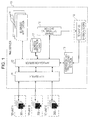
- Fig. 1 illustrates an exemplary configuration of a system according to an embodiment .
- client devices 301, 302, and 303, and a Web server 10 are connected to one another via a network including, for example, the Internet.
- the Web server 10 is an example of a computer (screen generation apparatus) executing a screen generation method.
- the Web server 10 provides a user with a service including screen transitions via the network.
- the Web server 10 provides a tenant (described later) with a service achieved through the functions of application software (hereinafter simply referred to as an "application” for purposes of description) via the Internet.
- Software as a Service can be used as an exemplary system configured to provide the services through the Web server 10.
- the Web server 10 is managed by the service provider.
- Each of the client devices 301, 302, 303, and so forth may be computer which belongs to the service user's part.
- the client devices 301, 302, and 303 belong to the individual tenants A, B, and C.
- the term "tenant” denotes an organization including a corporation, a group, and so forth, which makes a service utilization contract with the service provider. Therefore, the term “tenant” may denote a set of at least one user.
- the Web server 10 has software programs including a HyperText Transfer Protocol (HTTP) server 11, an application server 12, an expansion tag processing section 13, a business application 14, a tenant determining section 15, a screen definition data 17, and so forth.
- HTTP HyperText Transfer Protocol
- the HTTP server 11 controls communications performed between the HTTP server 11 and the client device 30.
- the HTTP server 11 receives request data (HTTP request data) transmitted from the client device 30, and transmits response data (HTTP response data) in response to the above-described request data in return.
- request data HTTP request data
- response data HTTP response data
- the application server 12 starts (calls) the business application 14 related to the request data transmitted from the client device 30 (related to a Uniform Resource Locator (URL)).
- the application server 12 generates screen data (Hypertext Markup Language (HTML) data) which is to be transmitted to the client device 30 in return based on the result of processing performed by the business application 14.
- the screen data is generated based on the screen definition data 17.
- Java registered trademark
- JSP Java
- the expansion tag processing unit 13 executes the processing corresponding to expansion tag data described in the screen definition data 17. Namely, the screen definition data 17 includes expansion tag data originally defined.
- the business application 14 may be a Web application. A plurality of the Web applications may be provided with reference to the functions. The business applications 14 may be e shared among at least two tenants.
- the tenant determining section 15 determines a tenant to which the client device 30 (user) functioning as the transmission source of the HTTP request belongs based on information included in the HTTP request received by the HTTP server 11.
- the tenant determining unit 15 adds (registers) identification information of the tenant corresponding to the determining result (hereinafter referred to as "tenant ID data") to session scope data 18.
- the term "session scope data” denotes data generated in a memory 103 so as to manage a session (and/or session information) established between the client device 30 and the Web server 10, and is usually referred to as a session object, for example.
- the tenant ID data is uniquely assigned to each tenant.
- the tenant ID data added to the session scope data 18 is referred to when the application server 12 generates screen data customized for each tenant through the expansion tag processing section 13.
- the session scope data 18 may be s used as an identifier storage section used to retain the tenant ID data in association with the client device 30. However, if the association with the client device 30 can be kept over a time period where the session is established, different data (storage area) may be used as the identifier storage section. Further, it may be arranged that the tenant ID data is used as cookie information as is the case with session ID data and transmitted from the client device 30 each time the HTTP request data is issued.
- Fig. 2 illustrates an exemplary hardware configuration of the Web server 10 according to the above-described embodiment.
- the Web server 10 illustrated in Fig. 2 includes a drive 100, an auxiliary storage device 102, the memory 103, a central processing unit (CPU) 104, and an interface 105 that are connected to one another via a bus 200.
- CPU central processing unit
- a program achieving processing performed through the Web server 10 is presented by a computer readable recording medium 101 including, for example, a compact disk (CD)-read only memory (ROM).
- a computer readable recording medium 101 including, for example, a compact disk (CD)-read only memory (ROM).
- CD compact disk
- ROM read only memory
- the program is installed from the recording medium 101 into the auxiliary storage device 102 via the drive 100.
- the program is not necessarily installed from the recording medium 101 into the auxiliary storage device 102. Namely, the program may be downloaded from a different computer via the network.
- the auxiliary storage device 102 stores the installed program and appropriate file data and/or data (e.g., the screen definition data 17), for example.
- the program read from the auxiliary storage device 102 is stored in the memory 103.
- the CPU 104 executes a function relating to the Web server 10 based on programs stored in the memory device 103.
- the interface 105 is used as an interface for connection to the network.
- Exemplary processing procedures performed by the web server 10 are e described with reference to Fig. 3 .
- the tenant determining section 15 determines whether the tenant ID data is registered with the session scope data 18 corresponding to a session with the client device 301 at operation S102.
- Each session is identified based on session ID data.
- the assignment of the session ID data is performed through the application server 12 when the session is established, and the session ID data is transmitted to the client device 301.
- the client device 301 retains the session ID data in cookies, for example, and transmits the session ID data to the Web server 10 each time the HTTP request is issued.
- the session scope data 18 is generated through the application server 12 as well as the session ID data when the session is established, and managed in association with the session ID data. Therefore, the tenant determining section 15 can acquire the session scope data 18 corresponding to the currently performed session based on the session ID data.
- the transmitted HTTP request data is data of a log-in request.
- the log-in request data includes data of a user ID (ID provided to identify each user) and password data that are transmitted for a log-in screen displayed on a Web browser of the client device 30. Therefore, in that case (when the answer is No at operation S102), the tenant determining section 15 determines the tenant ID data corresponding to the user ID data included in the HTTP request data (log-in request data) based on tenant ID management table data at operation S103.
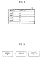
- Fig. 4 illustrates an exemplary configuration of tenant ID management table data 16.
- information about correspondence between the user ID data and the tenant ID data is registered with the tenant ID management table data 16.
- the user ID data included in the log-in request data denotes "user01 "
- the tenant determining section 15 determines that the tenant ID data corresponding to the user ID data denotes "AAA”.
- the tenant determining section 15 registers the tenant ID data which is the determination result with the session scope data 18 at operation S104.
- the HTTP request data transmitted from the client device 30 includes the tenant ID data. Therefore, the tenant ID data included in the HTTP request may be registered with the session scope data 18 as it is.
- the tenant ID data is automatically determined through the Web server 10 based on the user ID data. Consequently, each of the users of the tenant may not be informed of the tenant ID data. Further, each of the users may not store the tenant ID data and/or transmit the tenant ID data at login time so that the work load for the user is reduced.
- the application server 12 determines the business application 14 corresponding to the details of the HTTP request (for example, URL data included in the HTTP request data), and calls (and/or starts) the business application 14 at operation S105.
- the determination made by the business application 14, which corresponds to the details of the HTTP request, may be performed based on, for example, information about correspondence between the URL data and the business application 14, the correspondence information being stored in the auxiliary storage device 102.
- the called business application 14 executes a business logic installed therein at operation S106.
- the business application 14 requests the application server 12 to generate the screen data corresponding to the execution result.
- the business application 14 specifies the name of JSP file data used to generate the screen data and stores data of the specified name in the application server 12.
- the application server 12 generates screen data (HTML data) based on the JSP file specified by the business application 14 at operation S107.
- the application server 12 transmits the generated screen data to the HTTP server 11.
- the HTTP server 11 adds the screen data generated through the business application 14 to the HTTP response data, and transmits the HTTP response data to the client device 301 at operation S108.
- Processing illustrated in Fig. 3 is repeatedly executed so that a screen presented from the Web server 10 to the client device 301 (namely, a screen displayed on the client device 301) is caused to transition as illustrated in Fig. 5 .
- Fig. 5 illustrates exemplary screen transitions performed according to the above-described embodiment.
- the screen transitions are made in the order of a screen A, a screen B, and a screen C.
- the processing illustrated in Fig. 3 is performed once, the screen A is displayed on the client device 301.
- lf data of an operation instruction is transmitted through the screen A
- the processing illustrated in Fig. 3 is performed again based on the operation instruction data.
- the screen B is displayed on the client device 301.
- operation instruction data is transmitted through the screen B
- the processing illustrated in Fig. 3 is performed again based on the operation instruction data.
- the screen C is displayed on the client device 301.
- the client device 301 is exemplarily described in Figs. 3 and 5 , the same processing procedures and the same screen transitions are performed in the case where each of the client device 302 and client device 303 is used. In the above-described embodiment, however, at least one of the screens A, B, and C is customized and each tenant for displayed. For displaying a unique screen for each tenant, the screen definition data 17 according to the above-described embodiment has a configuration illustrated in Fig. 6 , for example.
- Fig. 6 illustrates an exemplary configuration of the screen definition data according to the above-described embodiment.
- the screen definition data 17 is a set of JSP file data items.
- the JSP file data items are divided and stored in folders based on the functions, rolls, and positions thereof.
- a root folder 171, a standard folder 172, a tenant-A folder 173, and a tenant-B folder 174 are illustrated as folders provided to store the JSP file data items.
- the root folder 171 is a root (the most significant) folder of a folder provided to store the screen definition data 17.
- the root folder 171 stores the JSP file data item functioning as include file data.
- the include file data denotes JSP file data in which definition (expansion tag) data used to call the expansion tag processing section 13 is described.
- the expansion tag processing section 13 selects screen definition file data used to generate the screen data from among the standard folder 172 and/or folders provided for the tenants (the tenant-A folder 173 and/or the tenant-B folder 174). Therefore, the include file data may be interpreted as JSP file data defined for selecting screen definition file data for use based on the tenant ID data.
- each of arrows extending from the include file data items to the screen definition file data items denotes the above-described selection relationship.
- the include file data is generated for a series of screens displayed during the screen transitions. Therefore, Fig. 6 illustrates the include file data 1711 corresponding to the screen A, the include file data 1712 corresponding to the screen B, and the include file data 1713 corresponding to the screen C. Further, in Fig. 6 , the path name of the root folder is determined to be "WEB-tNF/jsp". Further, the names of the include file data items are individually determined to be a. jsp, b. jsp, and c. jsp.
- Fig. 7 illustrates an exemplary definition of the include file data 1711
- the details of the definition of each of the include file data 1712 and the include file data 1713 may be equivalent to those of the definition of the include file data 1711.
- SaaS: include tag data 17120 is an example of expansion tag data used in the above-described embodiment. Namely, the SaaS: include tag data 17120 corresponds to a definition given to call the expansion tag processing section 13.
- Description data 17110 denotes the definition of a JSP standard and indicates a location where a definition which makes it possible to process the SaaS: include tag data 17120 is given.
- file data identified by data of the URL "http://fx-saas.net/r3/tags-htmt", the URL data being included in the description data 17110 includes information about correspondence between the SaaS: include tag data 17120 and the expansion tag processing section 13.
- the expansion tag processing section 13 is implemented as a class of Java (registered trademark). Therefore, more specific details of the correspondence information denote a definition of correspondence between the SaaS: include tag data and the class name of the expansion tag processing section 13.
- the standard folder 172 is provided to store the JSP file data (screen definition file data) including the definition information (screen definition data) used to generate a screen provided as standard (default) through the Web server 10.
- the standard folder 172 stores standard screen definition file data for each series of screen images relating to the screen transitions.
- Fig. 6 illustrates the screen definition file data 1721 corresponding to the screen A, the screen definition file data 1722 corresponding to the screen B, and the screen definition file data 172c corresponding to the screen C.
- the standard folder 172 is generated under the folder name "common" immediately under the root folder 171. Therefore, the path name of the standard folder is determined to be "WEB-IfVF/jsp/common".
- the names of the screen definition file data items that are included in the standard folder 172 are individually determined to be a. jsp, b. jsp, and c. jsp. Namely, in the above-described embodiment, the names of the screen definition file data items agree with the names of the corresponding include file data items.
- the file names of the screen definition file data items 1721, 1722, and 172c are individually determined to be "a. jsp", "b. jsp", and "c. jsp".
- the tenant-A folder 173 and the tenant-B folder 174 store screen definition file data items that are uniquely customized for the individual tenants A and B. However, each of the tenant folders does not necessarily store screen definition file data for every screen, but only stores screen definition file data for a screen which should be customized. For example, the tenant-A folder 173 stores screen definition file data 1731 provided for the screen A and screen definition file data 1732 provided for the screen C. Further, the tenant-B folder 174 only stores screen definition file 1741 provided for the screen B.
- each of the tenant-A folder 173 and the tenant-B folder 174 is generated immediately under the root folder by using the tenant ID data of each tenant as the folder name. Therefore, the path name of the tenant-A folder 173 is determined to be "WEB-INF/jsp/AAA”. Further, the path name of the tenant-B folder 174 is determined to be "WEB-INF/jsp/BBB”. Further, the name of the screen definition file data stored in each tenant folder agrees with the name of the corresponding include file data.
- the name of the screen definition file data 1731 is "a. jsp”.
- the name of the screen definition file data 1732 is "c. jsp”.
- the name of the screen definition file data 1741 is "b. jsp".
- Figs. 8A and 8B illustrate exemplary definitions of screen definition file data items.
- Fig. 8A illustrates an exemplary definition of standard screen definition file data 1711.
- Fig. 8B illustrates screen definition file data 1721 provided for a tenant A. Since the specific details of the definition are determined based on the specifications of a standard JSP, the description thereof will be omitted.
- the difference between the two screen definition file data items (descriptions 1715 and 1725 that are surrounded by broken lines as illustrated in Figs. 8A and 8B will be described.
- the description 1715 the character string "item for measurement search-and-list screen" is surrounded by a tag ⁇ h2>.
- the description 1725 the same character string is surrounded by a tag ⁇ h1>. Namely, on the screen A provided for the tenant A, the size of the character string "item for measurement search-and-list screen" is changed.
- the standard folder name is determined to be "common", and the name of each of the screen definition file data items agrees with the name of the corresponding include file data. Namely, each of the file data names is uniquely determined.
- the include file data may be defined as illustrated in Fig. 9 .
- Fig. 9 illustrates a second definition of the include file data.
- the same parts as those illustrated in Fig. 7 are designated by the same reference numerals, and the descriptions thereof will be omitted as appropriate.
- SaaS include tag data includes defaultJsp attribute data 1713 and jsp attribute data 1714.
- the value of the defaultJsp attribute data 1713 indicates the name of the standard folder 172 (namely, information provided to identify the standard folder 172).
- the value of the jsp attribute data 1714 indicates the name of the screen definition file data corresponding to the above-described include file data (namely, information provided to identify the screen definition file data).
- the path name of the standard screen definition file data of the screen A is determined to be "WEB-INF/jsp/defautt/aaaaa.jsp". Further, the path name of the screen definition file data used for the tenant A of the screen A is determined to be "WEB-INF/jsp/AAA/aaaaaa. jsp".
- each of the defaultJsp attribute and the jsp attribute can be defined for each include file data, that is, each screen. Therefore, it becomes possible to change the path name of the standard folder 171 and/or the name of the screen definition file data for each screen.
- Fig. 10 is a flowchart showing the procedure for performing screen data generation processing.
- the application server 12 acquires JSP file data specified by the business application 14, and executes the JSP file data.
- the JSP file data for execution corresponds to the include file data.
- the business application 14 specifies the file name of the screen A (a. jsp).
- the application server 12 acquires JSP file data relating to the file name (that is, the include file data) from the root folder 171, and executes the JSP file data.
- the application server 12 When the application server 12 detects the SaaS: include tag data while executing the include file data on a line-by-line basis (when the answer is Yes at operation S202), the application server 12 calls the expansion tag processing section 13. Calling the expansion tag processing section 13 in response to the detection of the SaaS: include tag data is determined based on, for example, the description data 17110 illustrated in Fig. 7 .
- the expansion tag processing section 13 responds to the call, and executes processing implemented therein at operation S203. After the processing performed by the expansion tag processing section 13 is finished, the screen data generation processing is finished.
- Fig. 11 is a flowchart showing processing procedures performed by the expansion tag processing section 13.
- the expansion tag processing section 13 acquires the tenant ID data from the session scope data 18 of a session for processing.
- the application server 12, the tenant determining section 15, and the expansion tag processing section 13 operate in the same sled. Therefore, it may be configured that the expansion tag processing section 13 is generated in the sled space defined in the application server 12 and the tenant determining section 15 refers to the session scope data 18 including the tenant ID data.
- the expansion tag processing section 13 generates the path name of the tenant folder by using the acquired tenant ID data at operation S302.
- the path name of the tenant folder data is obtained by adding the tenant ID to the path name of the root folder 171. Therefore, if the tenant ID denotes "AAA", for example, the path name of the tenant-A folder 173 is determined to be "WEB-INF/jsp/AAA".
- the expansion tag processing section 13 determines whether the JSP attribute data is specified in the SaaS: include tag data at operation S303. If the jsp attribute data is specified (when the answer is Yes at operation S303), the expansion tag processing section 13 determines what is obtained by adding the jsp-attribute value to the path name of the tenant folder data to be the path name of the screen definition file data for processing at operation S304. More specifically, if the value of the jsp attribute is "aaaaa. jsp", the path name of the screen definition file data becomes "WEB-INF/jsp/AAA/aaaaa. jsp".
- the expansion tag processing section n13 determines what is obtained by adding the file name of the include file data which is the current target for processing to the path name of the tenant folder data to be the path name of the screen definition file data for processing at operation S305. More specifically, if the name of the include file data which is the current target for processing is "a. jsp", the path name of the screen definition file data becomes "WEB-INF/jsp/AAA/a. jsp".
- the expansion tag processing section 13 determines whether screen definition file data relating to the generated path name exists at operation S306. If the screen definition file data exists (namely, if screen definition file data customized for a tenant relating to the tenant ID data exists), (when the answer is Yes at operation S306), the expansion tag processing section 13 makes the application server 12 execute the screen definition file data at operation S307. As a result, if screen definition file data stored in the tenant-A folder 173 is executed, for example, screen data customized for the tenant A is generated.
- the expansion tag processing section 13 determines whether the defaultJsp attribute data is specified in the SaaS: include tag data at operation S308. If the defaultJsp attribute data is specified (when the answer is Yes at operation S308), the expansion tag processing section 13 determines what is obtained by adding the value of the defaultJsp attribute data to the path name of the root folder to be the path name of the standard folder 171 of the transition destination screen at operation S309. More specifically, if the value of the defaultJsp attribute data is "default", the path name of the standard folder 171 is determined to be "WEB-INF/jsp/default".
- the expansion tag processing section 13 determines what is obtained by adding a predetermined folder name (common) to the path name of the root folder to be the path name of the standard folder 171 of the transition destination screen at operation S310. Therefore, the path name of the standard folder 171 becomes "WEB-INF/jsp/common".
- the expansion processing section 13 adds the name of the screen definition file data to the path name of the standard folder 171, and generates the path name of the standard screen definition file data at operation S311.
- the file name of the screen definition file data, which is added to the path name of the standard folder 171, is determined based on the determinations made at operation S303 to S305. Namely, if the jsp attribute data is specified in the include file data, the value of the jsp attribute data is adopted. Otherwise, the name of the include file data is adopted.
- the expansion tag processing section 13 makes the application server 12 execute screen definition file data relating to the generated path name at operation S312. As a result, standard screen data is generated based on the standard screen definition file data.
- the uniquely customized screen definition file data is used. If there is no uniquely customized screen definition file data, the standard screen definition file data (shared among all of the tenants) is used.
- the standard screen is displayed as the screen B for the tenant A.
- the standard screen is displayed as each of the screens A and C. Since no unique screen definition file data is generated for the tenant C, the standard screen is displayed for each screen.
- the screen definition file data may not be generated for every screen relating to the screen transitions.
- the screen definition file data may be generated for some screens that should be customized.
- the number of the screen definition file data items becomes smaller than in the case where the screen definition file data is generated for each screen. Consequently, it becomes possible to reduce the number of man-hours taken for generating the screen definition file data, the amount of storage available for the screen definition file data, and so forth.
- the tenant ID is replaced by the user ID data for executing the above-described embodiment.
- the user ID data may be added to the session scope data 18.
- the screen definition file data may be generated based on the user ID data. In that case, an example of the client identifier becomes not the tenant ID data, but the user ID data.
- data other than the JSP data may be used as the screen definition data.
- eXtensible Markup Language (XML) data and/or eXtensible Stylesheet Language (XSL) data may be used.
- XSL eXtensible Stylesheet Language
- ASP Active Server Pages
- Different data systems and/or originally defined data may be used.
- a distinction is drawn between the standard screen definition file data and the screen definition file data uniquely determined for each tenant by changing the storage destination folder to another.
- the above-described distinction may be drawn based on the file name.
- the tenant ID data may be included in the file name data.
- the standard screen definition file data and the screen definition file data provided for each tenant may be stored in the same folder.
- the above-described embodiment allows for reducing the cost to achieve a shift from the existing system where the screen customization for each tenant is performed with difficulty (namely, each tenant is provided with the standard screen) to another system.
- Screen definition data used in the system where each tenant is provided with the standard screen is usually configured as illustrated in Fig. 12 .
- Fig. 12 illustrates an exemplary configuration of the screen definition data used in the system where each tenant is provided with the standard screen.
- similar features as those illustrated in Fig. 6 are designated by the same reference numerals.
- the standard screen definition data items 1711, 1712, and 1713 are retained in the root folder 171.
- generation of the include file data, shifting the location where the standard screen definition data is stored, generation of screen definition data used for a tenant who desires the customization, and implementation of the expansion tag processing section 13 may be performed. Therefore, the coding of existing programs may not be changed. As a result, it becomes possible to shift to a system that can provide the screen customized for each tenant by performing relatively simple operations.
- the embodiments can be implemented in computing hardware (computing apparatus) and/or software, such as (in a non-limiting example) any computer that can store, retrieve, process and/or output data and/or communicate with other computers.
- the results produced can be displayed on a display of the computing hardware.
- a program/software implementing the embodiments may be recorded on computer-readable media comprising computer-readable recording media.
- the program/software implementing the embodiments may also be transmitted over transmission communication media.
- Examples of the computer-readable recording media include a magnetic recording apparatus, an optical disk, a magnetooptical disk, and/or a semiconductor memory (for example, RAM, ROM, etc.).
- Examples of the magnetic recording apparatus include a hard disk device (HDD), a flexible disk (FD), and a magnetic tape (MT).
- optical disk examples include a DVD (Digital Versatile Disc), a DVD-RAM, a CD-ROM (Compact Disc - Read Only Memory), and a CD-R (Recordable)/RW.
- communication media includes a carrier-wave signal.
Landscapes
- Engineering & Computer Science (AREA)
- Databases & Information Systems (AREA)
- Theoretical Computer Science (AREA)
- Data Mining & Analysis (AREA)
- Physics & Mathematics (AREA)
- General Engineering & Computer Science (AREA)
- General Physics & Mathematics (AREA)
- Information Transfer Between Computers (AREA)
- User Interface Of Digital Computer (AREA)
- Information Retrieval, Db Structures And Fs Structures Therefor (AREA)
Abstract
Description
- This application is related to and claims priority to Japanese Patent Application No.
2009- 29021, filed on February 10, 2009 - The embodiments discussed herein are directed to an image generation method and an image generation apparatus, and particularly to a method of generating a screen relating to a service provided via a network, and an apparatus configured to generate a screen.
- Conventionally, Web applications provided by, for example, application service providers (ASPs) have been configured to satisfy user needs. Therefore, an ASP company has customized a single application for each of users, and has managed and operated the applications separately. The above-described user denotes an organization which makes a service utilization contract with the ASP including a corporation, a group, a public office, and so forth.
- On the other hand, a system referred to as a Software as a Service (SaaS) can reduce a running cost by operating the same Web application on the same server and making a plurality of users use the same Web application (see Japanese Laid-open Patent Publication No.
2002-163382 - At that time, if the ASP company simply prepares data used to construct a plurality of screens for each user, so as to provide the each user with a uniquely customized screen, the amount of data for management increases so that the merit of the SaaS is diminished.
- It is an aspect of the embodiments discussed herein to provide a method, a recording medium, and an apparatus, the apparatus including a determining unit which determines, in response to a request to perform processing including a screen transition and the request is transmitted from a client device via a network, whether a screen definition data, as a transition destination, associated with a client identifier relating to the client device is stored in a screen definition data storage unit, and a generating unit which generates, when the screen definition data is stored, a data of the screen functioning as the transition destination by using the screen definition data and generates, when the screen definition data is not stored, a data of the screen functioning as the transition destination by using a common screen definition data.
- These together with other aspects and advantages which will be subsequently apparent, reside in the details of construction and operation as more fully hereinafter described and claimed, reference being had to the accompanying drawings forming a part hereof, wherein like numerals refer to like parts throughout.
-
-
Fig. 1 illustrates an exemplary configuration of a system according to an embodiment; -
Fig. 2 illustrates an exemplary hardware configuration of a Web server according to an embodiment; -
Fig. 3 is a flowchart showing processing procedures performed by the web server; -
Fig. 4 illustrates an exemplary configuration of tenant ID management-table data; -
Fig. 5 illustrates exemplary screen transitions according to the above-described embodiment; -
Fig. 6 illustrates an exemplary configuration of screen definition data according to the above-described embodiment; -
Fig. 7 illustrates an exemplary definition of include file data; -
Figs. 8A and 8B illustrate exemplary definitions of screen definition file data items; -
Fig. 9 illustrates a second definition of the include file data; -
Fig. 10 illustrates performing screen data generation processing; -
Fig. 11 illustrates processing procedures performed by an expansion tag processing section; -
Fig. 12 illustrates an exemplary configuration of screen definition data used in a system providing every tenant with a standard screen. -
Fig. 1 illustrates an exemplary configuration of a system according to an embodiment . InFig. 1 ,client devices Web server 10 are connected to one another via a network including, for example, the Internet. - The
Web server 10 is an example of a computer (screen generation apparatus) executing a screen generation method. TheWeb server 10 provides a user with a service including screen transitions via the network. TheWeb server 10 provides a tenant (described later) with a service achieved through the functions of application software (hereinafter simply referred to as an "application" for purposes of description) via the Internet. Software as a Service (SaaS) can be used as an exemplary system configured to provide the services through theWeb server 10. Here, theWeb server 10 is managed by the service provider. - Each of the
client devices client devices - The
Web server 10 has software programs including a HyperText Transfer Protocol (HTTP)server 11, an application server 12, an expansiontag processing section 13, abusiness application 14, atenant determining section 15, ascreen definition data 17, and so forth. - The
HTTP server 11 controls communications performed between theHTTP server 11 and the client device 30. For example, the HTTPserver 11 receives request data (HTTP request data) transmitted from the client device 30, and transmits response data (HTTP response data) in response to the above-described request data in return. - The application server 12 starts (calls) the
business application 14 related to the request data transmitted from the client device 30 (related to a Uniform Resource Locator (URL)). The application server 12 generates screen data (Hypertext Markup Language (HTML) data) which is to be transmitted to the client device 30 in return based on the result of processing performed by thebusiness application 14. The screen data is generated based on thescreen definition data 17. According to the above-described embodiment, Java (registered trademark) Server Pages (JSP) data is used as thescreen definition data 17. Consequently, the application server 12 includes JSP container data which is an environment where the JSP data is executed. - The expansion
tag processing unit 13 executes the processing corresponding to expansion tag data described in thescreen definition data 17. Namely, thescreen definition data 17 includes expansion tag data originally defined. - The
business application 14 may be a Web application. A plurality of the Web applications may be provided with reference to the functions. Thebusiness applications 14 may be e shared among at least two tenants. - The
tenant determining section 15 determines a tenant to which the client device 30 (user) functioning as the transmission source of the HTTP request belongs based on information included in the HTTP request received by theHTTP server 11. Thetenant determining unit 15 adds (registers) identification information of the tenant corresponding to the determining result (hereinafter referred to as "tenant ID data") to session scope data 18. The term "session scope data" denotes data generated in amemory 103 so as to manage a session (and/or session information) established between the client device 30 and theWeb server 10, and is usually referred to as a session object, for example. The tenant ID data is uniquely assigned to each tenant. The tenant ID data added to the session scope data 18 is referred to when the application server 12 generates screen data customized for each tenant through the expansiontag processing section 13. Further, the session scope data 18 may be s used as an identifier storage section used to retain the tenant ID data in association with the client device 30. However, if the association with the client device 30 can be kept over a time period where the session is established, different data (storage area) may be used as the identifier storage section. Further, it may be arranged that the tenant ID data is used as cookie information as is the case with session ID data and transmitted from the client device 30 each time the HTTP request data is issued. -
Fig. 2 illustrates an exemplary hardware configuration of theWeb server 10 according to the above-described embodiment. TheWeb server 10 illustrated inFig. 2 includes adrive 100, anauxiliary storage device 102, thememory 103, a central processing unit (CPU) 104, and aninterface 105 that are connected to one another via abus 200. - A program achieving processing performed through the
Web server 10 is presented by a computerreadable recording medium 101 including, for example, a compact disk (CD)-read only memory (ROM). When therecording medium 101 storing the program is set to thedrive 100, the program is installed from therecording medium 101 into theauxiliary storage device 102 via thedrive 100. However, the program is not necessarily installed from therecording medium 101 into theauxiliary storage device 102. Namely, the program may be downloaded from a different computer via the network. Theauxiliary storage device 102 stores the installed program and appropriate file data and/or data (e.g., the screen definition data 17), for example. - When an instruction to start the program is issued, the program read from the
auxiliary storage device 102 is stored in thememory 103. TheCPU 104 executes a function relating to theWeb server 10 based on programs stored in thememory device 103. Theinterface 105 is used as an interface for connection to the network. - Exemplary processing procedures performed by the
web server 10 are e described with reference toFig. 3 . - When the
HTTP server 11 receives the HTTP request transmitted from theclient device 301 at operation S101, thetenant determining section 15 determines whether the tenant ID data is registered with the session scope data 18 corresponding to a session with theclient device 301 at operation S102. - Each session is identified based on session ID data. The assignment of the session ID data is performed through the application server 12 when the session is established, and the session ID data is transmitted to the
client device 301. Theclient device 301 retains the session ID data in cookies, for example, and transmits the session ID data to theWeb server 10 each time the HTTP request is issued. Further, the session scope data 18 is generated through the application server 12 as well as the session ID data when the session is established, and managed in association with the session ID data. Therefore, thetenant determining section 15 can acquire the session scope data 18 corresponding to the currently performed session based on the session ID data. - If the tenant ID data is not registered with the session scope data 18 in the above-described embodiment, the transmitted HTTP request data is data of a log-in request. The log-in request data includes data of a user ID (ID provided to identify each user) and password data that are transmitted for a log-in screen displayed on a Web browser of the client device 30. Therefore, in that case (when the answer is No at operation S102), the
tenant determining section 15 determines the tenant ID data corresponding to the user ID data included in the HTTP request data (log-in request data) based on tenant ID management table data at operation S103. -
Fig. 4 illustrates an exemplary configuration of tenant IDmanagement table data 16. As illustrated inFig. 4 , information about correspondence between the user ID data and the tenant ID data is registered with the tenant IDmanagement table data 16. For example, the user ID data included in the log-in request data denotes "user01 ", thetenant determining section 15 determines that the tenant ID data corresponding to the user ID data denotes "AAA". - The
tenant determining section 15 registers the tenant ID data which is the determination result with the session scope data 18 at operation S104. - If each of the users of the tenant is notified of the tenant ID data, it may be arranged that the user transmits the tenant ID data at login time. In that case, the HTTP request data transmitted from the client device 30 includes the tenant ID data. Therefore, the tenant ID data included in the HTTP request may be registered with the session scope data 18 as it is.
- In the above-described embodiment, however, the tenant ID data is automatically determined through the
Web server 10 based on the user ID data. Consequently, each of the users of the tenant may not be informed of the tenant ID data. Further, each of the users may not store the tenant ID data and/or transmit the tenant ID data at login time so that the work load for the user is reduced. - On the other hand, when the tenant ID data had already been registered with the session scope data (namely, when the HTTP request data is data of a request to execute a business logic other than the log-in request) (when the answer is Yes at operation Sol 02), the processing corresponding to operations S103 and S104 is not performed.
- The application server 12 determines the
business application 14 corresponding to the details of the HTTP request (for example, URL data included in the HTTP request data), and calls (and/or starts) thebusiness application 14 at operation S105. The determination made by thebusiness application 14, which corresponds to the details of the HTTP request, may be performed based on, for example, information about correspondence between the URL data and thebusiness application 14, the correspondence information being stored in theauxiliary storage device 102. - The called
business application 14 executes a business logic installed therein at operation S106. When the execution of the business logic is finished, thebusiness application 14 requests the application server 12 to generate the screen data corresponding to the execution result. When issuing the screen-data generation request, thebusiness application 14 specifies the name of JSP file data used to generate the screen data and stores data of the specified name in the application server 12. - The application server 12 generates screen data (HTML data) based on the JSP file specified by the
business application 14 at operation S107. The application server 12 transmits the generated screen data to theHTTP server 11. TheHTTP server 11 adds the screen data generated through thebusiness application 14 to the HTTP response data, and transmits the HTTP response data to theclient device 301 at operation S108. - Processing illustrated in
Fig. 3 is repeatedly executed so that a screen presented from theWeb server 10 to the client device 301 (namely, a screen displayed on the client device 301) is caused to transition as illustrated inFig. 5 . -
Fig. 5 illustrates exemplary screen transitions performed according to the above-described embodiment. InFig. 5 , the screen transitions are made in the order of a screen A, a screen B, and a screen C. Namely, when the processing illustrated inFig. 3 is performed once, the screen A is displayed on theclient device 301. lf data of an operation instruction is transmitted through the screen A, the processing illustrated inFig. 3 is performed again based on the operation instruction data. As a result, the screen B is displayed on theclient device 301. When operation instruction data is transmitted through the screen B, the processing illustrated inFig. 3 is performed again based on the operation instruction data. As a result, the screen C is displayed on theclient device 301. - Although the
client device 301 is exemplarily described inFigs. 3 and5 , the same processing procedures and the same screen transitions are performed in the case where each of theclient device 302 andclient device 303 is used. In the above-described embodiment, however, at least one of the screens A, B, and C is customized and each tenant for displayed. For displaying a unique screen for each tenant, thescreen definition data 17 according to the above-described embodiment has a configuration illustrated inFig. 6 , for example. -
Fig. 6 illustrates an exemplary configuration of the screen definition data according to the above-described embodiment. In the above-described embodiment, thescreen definition data 17 is a set of JSP file data items. The JSP file data items are divided and stored in folders based on the functions, rolls, and positions thereof. InFig. 6 , aroot folder 171, astandard folder 172, a tenant-A folder 173, and a tenant-B folder 174 are illustrated as folders provided to store the JSP file data items. - The
root folder 171 is a root (the most significant) folder of a folder provided to store thescreen definition data 17. Theroot folder 171 stores the JSP file data item functioning as include file data. In the above-described embodiment, the include file data denotes JSP file data in which definition (expansion tag) data used to call the expansiontag processing section 13 is described. The expansiontag processing section 13 selects screen definition file data used to generate the screen data from among thestandard folder 172 and/or folders provided for the tenants (the tenant-A folder 173 and/or the tenant-B folder 174). Therefore, the include file data may be interpreted as JSP file data defined for selecting screen definition file data for use based on the tenant ID data. InFig. 6 , each of arrows extending from the include file data items to the screen definition file data items denotes the above-described selection relationship. - The include file data is generated for a series of screens displayed during the screen transitions. Therefore,
Fig. 6 illustrates the includefile data 1711 corresponding to the screen A, the includefile data 1712 corresponding to the screen B, and the includefile data 1713 corresponding to the screen C. Further, inFig. 6 , the path name of the root folder is determined to be "WEB-tNF/jsp". Further, the names of the include file data items are individually determined to be a. jsp, b. jsp, and c. jsp. - Although
Fig. 7 illustrates an exemplary definition of the includefile data 1711, the details of the definition of each of the includefile data 1712 and the includefile data 1713 may be equivalent to those of the definition of the includefile data 1711. - In
Fig. 7 , SaaS: includetag data 17120 is an example of expansion tag data used in the above-described embodiment. Namely, the SaaS: includetag data 17120 corresponds to a definition given to call the expansiontag processing section 13. - Description data 17110 denotes the definition of a JSP standard and indicates a location where a definition which makes it possible to process the SaaS: include
tag data 17120 is given. Namely, file data identified by data of the URL "http://fx-saas.net/r3/tags-htmt", the URL data being included in the description data 17110, includes information about correspondence between the SaaS: includetag data 17120 and the expansiontag processing section 13. In the above-described embodiment, the expansiontag processing section 13 is implemented as a class of Java (registered trademark). Therefore, more specific details of the correspondence information denote a definition of correspondence between the SaaS: include tag data and the class name of the expansiontag processing section 13. - Returning to
Fig. 6 , thestandard folder 172 is provided to store the JSP file data (screen definition file data) including the definition information (screen definition data) used to generate a screen provided as standard (default) through theWeb server 10. Thestandard folder 172 stores standard screen definition file data for each series of screen images relating to the screen transitions.Fig. 6 illustrates the screendefinition file data 1721 corresponding to the screen A, the screendefinition file data 1722 corresponding to the screen B, and the screen definition file data 172c corresponding to the screen C. Further, in the above-described embodiment, thestandard folder 172 is generated under the folder name "common" immediately under theroot folder 171. Therefore, the path name of the standard folder is determined to be "WEB-IfVF/jsp/common". Further, the names of the screen definition file data items that are included in thestandard folder 172 are individually determined to be a. jsp, b. jsp, and c. jsp. Namely, in the above-described embodiment, the names of the screen definition file data items agree with the names of the corresponding include file data items. The file names of the screen definitionfile data items - The tenant-
A folder 173 and the tenant-B folder 174 store screen definition file data items that are uniquely customized for the individual tenants A and B. However, each of the tenant folders does not necessarily store screen definition file data for every screen, but only stores screen definition file data for a screen which should be customized. For example, the tenant-A folder 173 stores screendefinition file data 1731 provided for the screen A and screendefinition file data 1732 provided for the screen C. Further, the tenant-B folder 174 only stores screendefinition file 1741 provided for the screen B. - In the above-described embodiment, each of the tenant-
A folder 173 and the tenant-B folder 174 is generated immediately under the root folder by using the tenant ID data of each tenant as the folder name. Therefore, the path name of the tenant-A folder 173 is determined to be "WEB-INF/jsp/AAA". Further, the path name of the tenant-B folder 174 is determined to be "WEB-INF/jsp/BBB". Further, the name of the screen definition file data stored in each tenant folder agrees with the name of the corresponding include file data. The name of the screendefinition file data 1731 is "a. jsp". The name of the screendefinition file data 1732 is "c. jsp". The name of the screendefinition file data 1741 is "b. jsp". -
Figs. 8A and 8B illustrate exemplary definitions of screen definition file data items.Fig. 8A illustrates an exemplary definition of standard screendefinition file data 1711.Fig. 8B illustrates screendefinition file data 1721 provided for a tenant A. Since the specific details of the definition are determined based on the specifications of a standard JSP, the description thereof will be omitted. Here, the difference between the two screen definition file data items (descriptions Figs. 8A and 8B will be described. According to thedescription 1715, the character string "item for measurement search-and-list screen" is surrounded by a tag <h2>. On the other hand, according to thedescription 1725, the same character string is surrounded by a tag <h1>. Namely, on the screen A provided for the tenant A, the size of the character string "item for measurement search-and-list screen" is changed. - The standard folder name is determined to be "common", and the name of each of the screen definition file data items agrees with the name of the corresponding include file data. Namely, each of the file data names is uniquely determined. For giving flexibility to the names of the standard folder and/or the screen definition file data, the include file data may be defined as illustrated in
Fig. 9 . -
Fig. 9 illustrates a second definition of the include file data. InFig. 9 , the same parts as those illustrated inFig. 7 are designated by the same reference numerals, and the descriptions thereof will be omitted as appropriate. - In
Fig. 9 , SaaS: include tag data includesdefaultJsp attribute data 1713 andjsp attribute data 1714. The value of thedefaultJsp attribute data 1713 indicates the name of the standard folder 172 (namely, information provided to identify the standard folder 172). The value of thejsp attribute data 1714 indicates the name of the screen definition file data corresponding to the above-described include file data (namely, information provided to identify the screen definition file data). - Therefore, according to the exemplary definition illustrated in
Fig. 9 , the path name of the standard screen definition file data of the screen A is determined to be "WEB-INF/jsp/defautt/aaaaaa.jsp". Further, the path name of the screen definition file data used for the tenant A of the screen A is determined to be "WEB-INF/jsp/AAA/aaaaaa. jsp". - By making the names of the
standard folder 172 and the screen definition file data changeable, flexibility can be given to the configuration of thestandard folder 172 and/or that of the screen definition file data. Further, each of the defaultJsp attribute and the jsp attribute can be defined for each include file data, that is, each screen. Therefore, it becomes possible to change the path name of thestandard folder 171 and/or the name of the screen definition file data for each screen. - Assuming that the
screen definition data 17 is configured as illustrated inFigs. 5 to 9 , the details of operation S107 illustrated inFig. 3 will be described.Fig. 10 is a flowchart showing the procedure for performing screen data generation processing. - At operation S201, the application server 12 acquires JSP file data specified by the
business application 14, and executes the JSP file data. Here, the JSP file data for execution corresponds to the include file data. For example, if the screen A is a screen which is the transition destination, thebusiness application 14 specifies the file name of the screen A (a. jsp). The application server 12 acquires JSP file data relating to the file name (that is, the include file data) from theroot folder 171, and executes the JSP file data. - When the application server 12 detects the SaaS: include tag data while executing the include file data on a line-by-line basis (when the answer is Yes at operation S202), the application server 12 calls the expansion
tag processing section 13. Calling the expansiontag processing section 13 in response to the detection of the SaaS: include tag data is determined based on, for example, the description data 17110 illustrated inFig. 7 . - The expansion
tag processing section 13 responds to the call, and executes processing implemented therein at operation S203. After the processing performed by the expansiontag processing section 13 is finished, the screen data generation processing is finished. - The details of operation S203 illustrated in
Fig. 10 will be described.Fig. 11 is a flowchart showing processing procedures performed by the expansiontag processing section 13. - At operation S301, the expansion
tag processing section 13 acquires the tenant ID data from the session scope data 18 of a session for processing. Here, the application server 12, thetenant determining section 15, and the expansiontag processing section 13 operate in the same sled. Therefore, it may be configured that the expansiontag processing section 13 is generated in the sled space defined in the application server 12 and thetenant determining section 15 refers to the session scope data 18 including the tenant ID data. - The expansion
tag processing section 13 generates the path name of the tenant folder by using the acquired tenant ID data at operation S302. In the above-described embodiment, the path name of the tenant folder data is obtained by adding the tenant ID to the path name of theroot folder 171. Therefore, if the tenant ID denotes "AAA", for example, the path name of the tenant-A folder 173 is determined to be "WEB-INF/jsp/AAA". - The expansion
tag processing section 13 determines whether the JSP attribute data is specified in the SaaS: include tag data at operation S303. If the jsp attribute data is specified (when the answer is Yes at operation S303), the expansiontag processing section 13 determines what is obtained by adding the jsp-attribute value to the path name of the tenant folder data to be the path name of the screen definition file data for processing at operation S304. More specifically, if the value of the jsp attribute is "aaaaaa. jsp", the path name of the screen definition file data becomes "WEB-INF/jsp/AAA/aaaaaa. jsp". - On the other hand, if no jsp attribute data is specified (when the answer is No at operation S303), the expansion tag processing section n13 determines what is obtained by adding the file name of the include file data which is the current target for processing to the path name of the tenant folder data to be the path name of the screen definition file data for processing at operation S305. More specifically, if the name of the include file data which is the current target for processing is "a. jsp", the path name of the screen definition file data becomes "WEB-INF/jsp/AAA/a. jsp".
- After operations S304 and S305, the expansion
tag processing section 13 determines whether screen definition file data relating to the generated path name exists at operation S306. If the screen definition file data exists (namely, if screen definition file data customized for a tenant relating to the tenant ID data exists), (when the answer is Yes at operation S306), the expansiontag processing section 13 makes the application server 12 execute the screen definition file data at operation S307. As a result, if screen definition file data stored in the tenant-A folder 173 is executed, for example, screen data customized for the tenant A is generated. - On the other hand, if no screen definition file data relating to the generated path name exist (when the answer is No at operation S306), the expansion
tag processing section 13 determines whether the defaultJsp attribute data is specified in the SaaS: include tag data at operation S308. If the defaultJsp attribute data is specified (when the answer is Yes at operation S308), the expansiontag processing section 13 determines what is obtained by adding the value of the defaultJsp attribute data to the path name of the root folder to be the path name of thestandard folder 171 of the transition destination screen at operation S309. More specifically, if the value of the defaultJsp attribute data is "default", the path name of thestandard folder 171 is determined to be "WEB-INF/jsp/default". - Further, if no defaultJsp attribute data is specified (when the answer is No at operation S308), the expansion
tag processing section 13 determines what is obtained by adding a predetermined folder name (common) to the path name of the root folder to be the path name of thestandard folder 171 of the transition destination screen at operation S310. Therefore, the path name of thestandard folder 171 becomes "WEB-INF/jsp/common". - After operation S308 and S309 are performed, the
expansion processing section 13 adds the name of the screen definition file data to the path name of thestandard folder 171, and generates the path name of the standard screen definition file data at operation S311. The file name of the screen definition file data, which is added to the path name of thestandard folder 171, is determined based on the determinations made at operation S303 to S305. Namely, if the jsp attribute data is specified in the include file data, the value of the jsp attribute data is adopted. Otherwise, the name of the include file data is adopted. - The expansion
tag processing section 13 makes the application server 12 execute screen definition file data relating to the generated path name at operation S312. As a result, standard screen data is generated based on the standard screen definition file data. - Thus, according to the above-described embodiment, if there is the screen definition file data uniquely customized for the tenant when a series of screens relating to the screen transitions is generated, the uniquely customized screen definition file data is used. If there is no uniquely customized screen definition file data, the standard screen definition file data (shared among all of the tenants) is used.
- For example, if the screen definition file data is generated as illustrated in
Fig. 6 , the standard screen is displayed as the screen B for the tenant A. For the tenant B, the standard screen is displayed as each of the screens A and C. Since no unique screen definition file data is generated for the tenant C, the standard screen is displayed for each screen. - Therefore, the screen definition file data may not be generated for every screen relating to the screen transitions. In other words, the screen definition file data may be generated for some screens that should be customized. As a result, the number of the screen definition file data items becomes smaller than in the case where the screen definition file data is generated for each screen. Consequently, it becomes possible to reduce the number of man-hours taken for generating the screen definition file data, the amount of storage available for the screen definition file data, and so forth.
- In the case of determining the unit of customization not for each tenant, but for each user (the user denotes a single person in the above-described embodiment), the tenant ID is replaced by the user ID data for executing the above-described embodiment. The user ID data may be added to the session scope data 18. Further, the screen definition file data may be generated based on the user ID data. In that case, an example of the client identifier becomes not the tenant ID data, but the user ID data.
- Further, data other than the JSP data may be used as the screen definition data. For example, eXtensible Markup Language (XML) data and/or eXtensible Stylesheet Language (XSL) data may be used. Further, Active Server Pages (ASP) data may be used. Different data systems and/or originally defined data may be used.
- Further, in the above-described embodiment, a distinction is drawn between the standard screen definition file data and the screen definition file data uniquely determined for each tenant by changing the storage destination folder to another. However, the above-described distinction may be drawn based on the file name. For example, for the screen definition file data uniquely determined for each tenant, the tenant ID data may be included in the file name data. In that case, the standard screen definition file data and the screen definition file data provided for each tenant may be stored in the same folder.
- Incidentally, the above-described embodiment allows for reducing the cost to achieve a shift from the existing system where the screen customization for each tenant is performed with difficulty (namely, each tenant is provided with the standard screen) to another system. Screen definition data used in the system where each tenant is provided with the standard screen is usually configured as illustrated in
Fig. 12 . -
Fig. 12 illustrates an exemplary configuration of the screen definition data used in the system where each tenant is provided with the standard screen. InFig. 12 , similar features as those illustrated inFig. 6 are designated by the same reference numerals. - In the system where each tenant is provided with the standard screen as illustrated in
Fig. 12 , the standard screendefinition data items root folder 171. For shifting from the above-described state to that illustrated inFig. 6 , generation of the include file data, shifting the location where the standard screen definition data is stored, generation of screen definition data used for a tenant who desires the customization, and implementation of the expansiontag processing section 13 may be performed. Therefore, the coding of existing programs may not be changed. As a result, it becomes possible to shift to a system that can provide the screen customized for each tenant by performing relatively simple operations. - The embodiments can be implemented in computing hardware (computing apparatus) and/or software, such as (in a non-limiting example) any computer that can store, retrieve, process and/or output data and/or communicate with other computers. The results produced can be displayed on a display of the computing hardware. A program/software implementing the embodiments may be recorded on computer-readable media comprising computer-readable recording media. The program/software implementing the embodiments may also be transmitted over transmission communication media. Examples of the computer-readable recording media include a magnetic recording apparatus, an optical disk, a magnetooptical disk, and/or a semiconductor memory (for example, RAM, ROM, etc.). Examples of the magnetic recording apparatus include a hard disk device (HDD), a flexible disk (FD), and a magnetic tape (MT). Examples of the optical disk include a DVD (Digital Versatile Disc), a DVD-RAM, a CD-ROM (Compact Disc - Read Only Memory), and a CD-R (Recordable)/RW. An example of communication media includes a carrier-wave signal.
- Further, according to an aspect of the embodiments, any combinations of the described features, functions and/or operations can be provided.
- The many features and advantages of the embodiments are apparent from the detailed specification and, thus, it is intended by the appended claims to cover all such features and advantages of the embodiments that fall within the true spirit and scope thereof. Further, since numerous modifications and changes will readily occur to those skilled in the art, it is not desired to limit the inventive embodiments to the exact construction and operation illustrated and described, and accordingly all suitable modifications and equivalents may be resorted to, falling within the scope thereof.
Claims (10)
- A screen generation method executed by a computer, the screen generation method comprising:determining, in response to a request to perform processing including a screen transition and the request is transmitted from a client device via a network, whether a screen definition data, as a transition destination, associated with a client identifier relating to the client device is stored in a screen definition data storage unit, andgenerating, when the screen definition data is stored, a data of the screen functioning as the transition destination by using the screen definition data and generating, when the screen definition data is not stored, a data of the screen functioning as the transition destination by using a common screen definition data .
- The screen generation method according to Claim 1, wherein
the screen definition data storage stores definition data used to perform the determination and the generation for each series of screens relating to the screen transition, and
the determination and the generation are performed based on the definition data corresponding to the screen functioning as the transition destination in response to the processing request. - The screen generation method according to Claim 1, wherein
the determination determines whether a screen definition data associated with a tenant identifier associated with the client identifier relating to the client device is stored in a screen definition data storage unit. - A screen generation apparatus comprising:a determining unit which determines, in response to a request to perform processing including a screen transition and the request is transmitted from a client device via a network, whether a screen definition data, as a transition destination, associated with a client identifier relating to the client device is stored in a screen definition data storage unit, anda generating unit which generates, when the screen definition data is stored, a data of the screen functioning as the transition destination by using the screen definition data and generates, when the screen definition data is not stored, a data of the screen functioning as the transition destination by using a common screen definition data.
- The screen generation apparatus according to Claim 4, wherein
the screen definition data storage stores definition data used to perform the determination and the generation for each series of screens relating to the screen transition, and
the determining unit and the generating unit perform based on the definition data corresponding to the screen functioning as the transition destination in response to the processing request. - The screen generation apparatus according to Claim 5, wherein
the determining unit determines whether a screen definition data associated with a tenant identifier associated with the client identifier relating to the client device is stored in a screen definition data storage unit. - A recording medium recording a screen generation program to be executed to perform a process comprising:determining, in response to a request to perform processing including a screen transition and the request is transmitted from a client device via a network, whether a screen definition data, as a transition destination, associated with a client identifier relating to the client device is stored in a screen definition data storage unit, andgenerating, when the screen definition data is stored, a data of the screen functioning as the transition destination by using the screen definition data and generating, when the screen definition data is not stored, a data of the screen functioning as the transition destination by using a common screen definition data.
- The recording medium according to Claim 7, wherein
the screen definition data storage stores definition data used to perform the determination and the generation for each series of screens relating to the screen transition, and
the determination and the generation are performed based on the definition data corresponding to the screen functioning as the transition destination in response to the processing request. - The recording medium according to Claim 8, wherein
the determination determines whether a screen definition data associated with a tenant identifier associated with the client identifier relating to the client device is stored in a screen definition data storage unit. - A method comprising:determining with a microprocessor whether screen definition data, as a transition destination associated with a client identifier relating to a client device, is stored;generating, upon determining the screen definition data is stored, data of screen functioning as the transition destination using the stored screen definition data; andgenerating, upon determining the screen definition data not being stored, data of the screen functioning as the transition destination by using common screen definition data .
Applications Claiming Priority (1)
| Application Number | Priority Date | Filing Date | Title |
|---|---|---|---|
| JP2009029021A JP5638761B2 (en) | 2009-02-10 | 2009-02-10 | Screen generation method, screen display method, screen generation device, and program |
Publications (2)
| Publication Number | Publication Date |
|---|---|
| EP2216723A2 true EP2216723A2 (en) | 2010-08-11 |
| EP2216723A3 EP2216723A3 (en) | 2011-01-12 |
Family
ID=42235472
Family Applications (1)
| Application Number | Title | Priority Date | Filing Date |
|---|---|---|---|
| EP09176681A Ceased EP2216723A3 (en) | 2009-02-10 | 2009-11-20 | Screen generation method, and screen generation apparatus |
Country Status (3)
| Country | Link |
|---|---|
| US (1) | US9223896B2 (en) |
| EP (1) | EP2216723A3 (en) |
| JP (1) | JP5638761B2 (en) |
Cited By (1)
| Publication number | Priority date | Publication date | Assignee | Title |
|---|---|---|---|---|
| US9661184B2 (en) | 2014-10-31 | 2017-05-23 | Ricoh Company, Ltd. | Data processing system and data processing method for authenticating user by utilizing user list obtained from service providing apparatus |
Families Citing this family (7)
| Publication number | Priority date | Publication date | Assignee | Title |
|---|---|---|---|---|
| US20100174992A1 (en) * | 2009-01-04 | 2010-07-08 | Leon Portman | System and method for screen recording |
| US9715555B2 (en) * | 2010-02-26 | 2017-07-25 | Salesforce.Com, Inc. | System, method and computer program product for user registration with a multi-tenant on-demand database system |
| US8566923B2 (en) * | 2011-02-01 | 2013-10-22 | Rockwell Automation Technologies, Inc. | Enhanced organization and automatic navigation of display screens facilitating automation control |
| JP5882623B2 (en) * | 2011-08-03 | 2016-03-09 | キヤノン株式会社 | Information processing apparatus, control method, and program |
| US9826027B2 (en) * | 2014-08-19 | 2017-11-21 | Bank Of America Corporation | User interfaces generated by a workflow engine |
| JP6492642B2 (en) * | 2014-12-25 | 2019-04-03 | ブラザー工業株式会社 | Image forming apparatus, image forming system, and program |
| US10645173B2 (en) * | 2017-10-30 | 2020-05-05 | International Business Machines Corporation | Session handling for multi-user multi-tenant web applications |
Citations (1)
| Publication number | Priority date | Publication date | Assignee | Title |
|---|---|---|---|---|
| JP2002163382A (en) | 2000-11-29 | 2002-06-07 | Fujitsu Ltd | Customization method for ASP service |
Family Cites Families (23)
| Publication number | Priority date | Publication date | Assignee | Title |
|---|---|---|---|---|
| JP3535267B2 (en) * | 1995-07-03 | 2004-06-07 | 富士通株式会社 | Monitoring system display device for monitoring system |
| US5999179A (en) * | 1997-11-17 | 1999-12-07 | Fujitsu Limited | Platform independent computer network management client |
| US6697088B1 (en) * | 1998-04-27 | 2004-02-24 | Jacada, Inc. | Graphical presentation system |
| US6263346B1 (en) * | 1998-07-17 | 2001-07-17 | International Business Machines Corporation | Network with storage of all client computer programs in server computer having customized client graphical user interfaces with maximum sharing of stored portions of interfaces common to a plurality of clients |
| US6505246B1 (en) * | 1998-12-30 | 2003-01-07 | Candle Distributed Solutions, Inc. | User interface for system management applications |
| TW494319B (en) * | 1999-11-29 | 2002-07-11 | Citicorp Developmemt Ct Inc | A method and system for generating display screen templates |
| US6954751B2 (en) * | 2000-09-06 | 2005-10-11 | Oracle International Corporation | Accessing data stored at an intermediary from a service |
| EP1205843A3 (en) * | 2000-11-13 | 2004-10-20 | Canon Kabushiki Kaisha | User interfaces |
| EP1220507A1 (en) * | 2000-12-22 | 2002-07-03 | Sun Microsystems, Inc. | Creating web content in a client and server system |
| GB0108354D0 (en) * | 2001-04-03 | 2001-05-23 | Thirdspace Living Ltd | System and method for providing a user with access to a plurality of sevices and content from a broadband television service |
| US7038588B2 (en) * | 2001-05-04 | 2006-05-02 | Draeger Medical Infant Care, Inc. | Apparatus and method for patient point-of-care data management |
| JP2003044417A (en) | 2001-07-30 | 2003-02-14 | Kernel:Kk | Client-server system structuring method equipped with managing function and interactive function |
| US8112493B2 (en) | 2004-01-16 | 2012-02-07 | International Business Machines Corporation | Programmatic role-based security for a dynamically generated user interface |
| JP2005266946A (en) * | 2004-03-16 | 2005-09-29 | Ricoh Co Ltd | Information processing apparatus, information processing method, information processing program, and recording medium |
| JP4564488B2 (en) * | 2004-04-05 | 2010-10-20 | パナソニック株式会社 | Screen transition control device |
| JP2006031666A (en) * | 2004-06-17 | 2006-02-02 | Epson Avasys Corp | Electronic document browsing system |
| JP2007282199A (en) * | 2006-03-15 | 2007-10-25 | Ricoh Co Ltd | Flow mounting system, flow mounting method, flow mounting program, and image processing apparatus |
| JP2007279974A (en) * | 2006-04-05 | 2007-10-25 | Ricoh Co Ltd | Display screen control device, electronic device, display screen control system, display screen control method, screen display method, display screen control program, and screen display program |
| WO2007115863A1 (en) * | 2006-04-12 | 2007-10-18 | International Business Machines Corporation | Method and system for adjusting environment settings to the capabilities of a client device |
| JP2007316904A (en) * | 2006-05-25 | 2007-12-06 | Ricoh Co Ltd | Web application system, Web application screen providing method, and program thereof |
| JPWO2008075492A1 (en) * | 2006-12-19 | 2010-04-08 | 三菱電機株式会社 | Map display device |
| CN101334865A (en) * | 2007-06-28 | 2008-12-31 | 国际商业机器公司 | Working stream user interface creation method and creator |
| US20110010394A1 (en) * | 2009-07-08 | 2011-01-13 | International Business Machines Corporation | Client-specific data customization for shared databases |
-
2009
- 2009-02-10 JP JP2009029021A patent/JP5638761B2/en not_active Expired - Fee Related
- 2009-11-13 US US12/618,160 patent/US9223896B2/en not_active Expired - Fee Related
- 2009-11-20 EP EP09176681A patent/EP2216723A3/en not_active Ceased
Patent Citations (1)
| Publication number | Priority date | Publication date | Assignee | Title |
|---|---|---|---|---|
| JP2002163382A (en) | 2000-11-29 | 2002-06-07 | Fujitsu Ltd | Customization method for ASP service |
Cited By (1)
| Publication number | Priority date | Publication date | Assignee | Title |
|---|---|---|---|---|
| US9661184B2 (en) | 2014-10-31 | 2017-05-23 | Ricoh Company, Ltd. | Data processing system and data processing method for authenticating user by utilizing user list obtained from service providing apparatus |
Also Published As
| Publication number | Publication date |
|---|---|
| US9223896B2 (en) | 2015-12-29 |
| JP2010186264A (en) | 2010-08-26 |
| EP2216723A3 (en) | 2011-01-12 |
| JP5638761B2 (en) | 2014-12-10 |
| US20110083083A1 (en) | 2011-04-07 |
Similar Documents
| Publication | Publication Date | Title |
|---|---|---|
| US9223896B2 (en) | Screen generation method, and screen generation apparatus | |
| US10049161B2 (en) | Information processing apparatus, method of controlling the same, and storage medium | |
| US7949999B1 (en) | Providing support for multiple interface access to software services | |
| US20050114448A1 (en) | System and method for delegation of data processing tasks based on device physical attributes and spatial behavior | |
| US8914772B2 (en) | Prescribing a software architecture for implementing service integration | |
| EP2241967A2 (en) | Information processing apparatus, control method, and program | |
| US20150081798A1 (en) | Process-based inter-thing collaboration apparatus and method in web of things environment | |
| JP2010016778A (en) | Image forming apparatus, information processing method, and image forming system | |
| US7809837B2 (en) | User interface for configuring web services for remote portlets | |
| JP2010027007A (en) | Processing device, requesting device, and processing method thereof | |
| US9769246B2 (en) | Information processing terminal and control method | |
| US20120113461A1 (en) | Image processing apparatus for processing document data and control method therefor | |
| US7502853B2 (en) | System and method for improved remote portlet communications | |
| JP2010092128A (en) | Apparatus, method and program for converting site information | |
| GB2506369A (en) | Control of service requests communication in a web runtime environment | |
| CN115495065A (en) | Page component arrangement and combination method and device based on business flow control | |
| JP4714463B2 (en) | Method for inheriting data between user terminal device and Web application | |
| JP6128503B1 (en) | Program, server and system for providing services related to electronic manuals | |
| JP2010061635A (en) | Web page built-in type sns system and sns server device thereof | |
| JP7526863B1 (en) | Shared email system, transmission method, and program | |
| JP7515667B1 (en) | Groupware system, display control method, and program | |
| KR20040001346A (en) | Method for customized application service by composing compoments chosen by customer | |
| JP2011237960A (en) | Service invitation system, client device, service invitation method | |
| JP2007264928A (en) | Information providing apparatus, information providing method, and information providing program | |
| KR101414844B1 (en) | Method and apparatus for moving web object using push |
Legal Events
| Date | Code | Title | Description |
|---|---|---|---|
| PUAI | Public reference made under article 153(3) epc to a published international application that has entered the european phase |
Free format text: ORIGINAL CODE: 0009012 |
|
| AK | Designated contracting states |
Kind code of ref document: A2 Designated state(s): AT BE BG CH CY CZ DE DK EE ES FI FR GB GR HR HU IE IS IT LI LT LU LV MC MK MT NL NO PL PT RO SE SI SK SM TR |
|
| AX | Request for extension of the european patent |
Extension state: AL BA RS |
|
| PUAL | Search report despatched |
Free format text: ORIGINAL CODE: 0009013 |
|
| AK | Designated contracting states |
Kind code of ref document: A3 Designated state(s): AT BE BG CH CY CZ DE DK EE ES FI FR GB GR HR HU IE IS IT LI LT LU LV MC MK MT NL NO PL PT RO SE SI SK SM TR |
|
| AX | Request for extension of the european patent |
Extension state: AL BA RS |
|
| 17P | Request for examination filed |
Effective date: 20110706 |
|
| 17Q | First examination report despatched |
Effective date: 20150211 |
|
| STAA | Information on the status of an ep patent application or granted ep patent |
Free format text: STATUS: THE APPLICATION HAS BEEN REFUSED |
|
| 18R | Application refused |
Effective date: 20170511 |