EP2216675B1 - Night vision goggle compatible lighting device with light-emitting diodes - Google Patents
Night vision goggle compatible lighting device with light-emitting diodes Download PDFInfo
- Publication number
- EP2216675B1 EP2216675B1 EP10152142A EP10152142A EP2216675B1 EP 2216675 B1 EP2216675 B1 EP 2216675B1 EP 10152142 A EP10152142 A EP 10152142A EP 10152142 A EP10152142 A EP 10152142A EP 2216675 B1 EP2216675 B1 EP 2216675B1
- Authority
- EP
- European Patent Office
- Prior art keywords
- red
- diodes
- blue
- green
- light
- Prior art date
- Legal status (The legal status is an assumption and is not a legal conclusion. Google has not performed a legal analysis and makes no representation as to the accuracy of the status listed.)
- Active
Links
- 230000004297 night vision Effects 0.000 title claims description 7
- 230000003287 optical effect Effects 0.000 claims abstract description 14
- 230000003595 spectral effect Effects 0.000 claims abstract description 12
- 230000005540 biological transmission Effects 0.000 claims abstract description 5
- 230000003321 amplification Effects 0.000 description 5
- 238000003199 nucleic acid amplification method Methods 0.000 description 5
- 230000005855 radiation Effects 0.000 description 5
- 230000004907 flux Effects 0.000 description 4
- 238000004737 colorimetric analysis Methods 0.000 description 3
- JEIPFZHSYJVQDO-UHFFFAOYSA-N iron(III) oxide Inorganic materials O=[Fe]O[Fe]=O JEIPFZHSYJVQDO-UHFFFAOYSA-N 0.000 description 3
- 238000000295 emission spectrum Methods 0.000 description 2
- 238000001914 filtration Methods 0.000 description 2
- 238000005286 illumination Methods 0.000 description 2
- 238000001228 spectrum Methods 0.000 description 2
- 238000001429 visible spectrum Methods 0.000 description 2
- 229920000297 Rayon Polymers 0.000 description 1
- 241001080024 Telles Species 0.000 description 1
- 230000007423 decrease Effects 0.000 description 1
- 238000005516 engineering process Methods 0.000 description 1
- 230000007613 environmental effect Effects 0.000 description 1
- 238000010304 firing Methods 0.000 description 1
- 239000000383 hazardous chemical Substances 0.000 description 1
- 239000004973 liquid crystal related substance Substances 0.000 description 1
- 239000011159 matrix material Substances 0.000 description 1
- 238000000034 method Methods 0.000 description 1
- 239000000203 mixture Substances 0.000 description 1
- 238000005457 optimization Methods 0.000 description 1
- 239000002964 rayon Substances 0.000 description 1
- 229920006395 saturated elastomer Polymers 0.000 description 1
- 230000035945 sensitivity Effects 0.000 description 1
- 239000007787 solid Substances 0.000 description 1
- 238000012800 visualization Methods 0.000 description 1
Images
Classifications
-
- G—PHYSICS
- G02—OPTICS
- G02B—OPTICAL ELEMENTS, SYSTEMS OR APPARATUS
- G02B27/00—Optical systems or apparatus not provided for by any of the groups G02B1/00 - G02B26/00, G02B30/00
- G02B27/01—Head-up displays
- G02B27/017—Head mounted
- G02B27/0172—Head mounted characterised by optical features
-
- G—PHYSICS
- G02—OPTICS
- G02F—OPTICAL DEVICES OR ARRANGEMENTS FOR THE CONTROL OF LIGHT BY MODIFICATION OF THE OPTICAL PROPERTIES OF THE MEDIA OF THE ELEMENTS INVOLVED THEREIN; NON-LINEAR OPTICS; FREQUENCY-CHANGING OF LIGHT; OPTICAL LOGIC ELEMENTS; OPTICAL ANALOGUE/DIGITAL CONVERTERS
- G02F1/00—Devices or arrangements for the control of the intensity, colour, phase, polarisation or direction of light arriving from an independent light source, e.g. switching, gating or modulating; Non-linear optics
- G02F1/01—Devices or arrangements for the control of the intensity, colour, phase, polarisation or direction of light arriving from an independent light source, e.g. switching, gating or modulating; Non-linear optics for the control of the intensity, phase, polarisation or colour
- G02F1/13—Devices or arrangements for the control of the intensity, colour, phase, polarisation or direction of light arriving from an independent light source, e.g. switching, gating or modulating; Non-linear optics for the control of the intensity, phase, polarisation or colour based on liquid crystals, e.g. single liquid crystal display cells
- G02F1/133—Constructional arrangements; Operation of liquid crystal cells; Circuit arrangements
- G02F1/1333—Constructional arrangements; Manufacturing methods
- G02F1/1335—Structural association of cells with optical devices, e.g. polarisers or reflectors
- G02F1/1336—Illuminating devices
- G02F1/133602—Direct backlight
- G02F1/133603—Direct backlight with LEDs
-
- G—PHYSICS
- G02—OPTICS
- G02B—OPTICAL ELEMENTS, SYSTEMS OR APPARATUS
- G02B27/00—Optical systems or apparatus not provided for by any of the groups G02B1/00 - G02B26/00, G02B30/00
- G02B27/01—Head-up displays
- G02B27/0101—Head-up displays characterised by optical features
- G02B2027/0112—Head-up displays characterised by optical features comprising device for genereting colour display
-
- G—PHYSICS
- G02—OPTICS
- G02B—OPTICAL ELEMENTS, SYSTEMS OR APPARATUS
- G02B5/00—Optical elements other than lenses
- G02B5/20—Filters
- G02B5/28—Interference filters
-
- G—PHYSICS
- G02—OPTICS
- G02F—OPTICAL DEVICES OR ARRANGEMENTS FOR THE CONTROL OF LIGHT BY MODIFICATION OF THE OPTICAL PROPERTIES OF THE MEDIA OF THE ELEMENTS INVOLVED THEREIN; NON-LINEAR OPTICS; FREQUENCY-CHANGING OF LIGHT; OPTICAL LOGIC ELEMENTS; OPTICAL ANALOGUE/DIGITAL CONVERTERS
- G02F1/00—Devices or arrangements for the control of the intensity, colour, phase, polarisation or direction of light arriving from an independent light source, e.g. switching, gating or modulating; Non-linear optics
- G02F1/01—Devices or arrangements for the control of the intensity, colour, phase, polarisation or direction of light arriving from an independent light source, e.g. switching, gating or modulating; Non-linear optics for the control of the intensity, phase, polarisation or colour
- G02F1/13—Devices or arrangements for the control of the intensity, colour, phase, polarisation or direction of light arriving from an independent light source, e.g. switching, gating or modulating; Non-linear optics for the control of the intensity, phase, polarisation or colour based on liquid crystals, e.g. single liquid crystal display cells
- G02F1/133—Constructional arrangements; Operation of liquid crystal cells; Circuit arrangements
- G02F1/1333—Constructional arrangements; Manufacturing methods
- G02F1/1335—Structural association of cells with optical devices, e.g. polarisers or reflectors
- G02F1/1336—Illuminating devices
- G02F1/133626—Illuminating devices providing two modes of illumination, e.g. day-night
-
- G—PHYSICS
- G02—OPTICS
- G02F—OPTICAL DEVICES OR ARRANGEMENTS FOR THE CONTROL OF LIGHT BY MODIFICATION OF THE OPTICAL PROPERTIES OF THE MEDIA OF THE ELEMENTS INVOLVED THEREIN; NON-LINEAR OPTICS; FREQUENCY-CHANGING OF LIGHT; OPTICAL LOGIC ELEMENTS; OPTICAL ANALOGUE/DIGITAL CONVERTERS
- G02F2203/00—Function characteristic
- G02F2203/05—Function characteristic wavelength dependent
- G02F2203/055—Function characteristic wavelength dependent wavelength filtering
Definitions
- the field of the invention is that of "NVG” compatible light-emitting diodes for flat displays of visualizations such as liquid crystal matrices.
- “NVG” compatible lighting means lighting that can be used with “NVG” light amplification binoculars for "Night Vision Goggle", that is, the lighting does not saturate the lighting systems. amplification binoculars.
- Lighting devices are also known in the Anglo-Saxon terminology of "backlighting".
- Flat screens have multiple applications, they can be used, for example, to make devices for displaying aircraft dashboards.
- LCD flat panel lighting was initially provided by fluorescent tubes, generally of the CCFL type, which stands for Cold Cathod Fluorescent Light.
- This technology has a number of disadvantages. These include obsolescence issues, the need for a high-voltage power supply, high power consumption, and compatibility issues with the new RoHS environmental standards, which stands for “Restriction of Use of Certain Hazardous Substances”. electrical and electronic equipment ". To be “NVG” compatible and not to saturate binocular amplification devices, fluorescent tube lights include optical filters, which adds additional difficulty.
- the diodes are point or quasi-point light sources emitting in a given emission cone, most of the diodes having a Lambertian emission profile.
- the lighting device may consist of a "carpet" of light-emitting diodes arranged under the screen.
- three types of diodes emitting in three different spectral bands in the visible spectrum are used so that the mixture of emitted beams gives a white light.
- the diodes emit in red, green and blue.
- Night vision binocular amplification devices are known to have a significant amplification coefficient in a spectral band starting at the red end of the visible spectrum, around 650 nanometers and ending in the near infrared, around 930 nanometers.
- the diodes emitting in the green or in the blue are naturally compatible "NVG", their emission in the red or the near infrared being very weak or non-existent It is not the same of the diodes emitting in the red which must be filtered so that the binoculars are not saturated
- the problem of filtering is not simple: it must be sufficient to ensure NVG compatibility and not be too important for the colorimetry to remain correct.
- NVG compatibility is subject to international standards such as the MIL STD 3009, which are particularly stringent. Since in a large number of applications red is associated with the alarms and must be clearly identified as such, it should also be noted that the sensitivity of the eye decreases very rapidly. in the red part of the spectrum, further complicating the implementation of the filter. Finally, not all types of red diodes have exactly the same spectral distribution. Thus, each diode change is accompanied by a new optimization of the filtering means.
- US2007171623 describes a lighting system compatible with night vision binoculars that includes a blue, green, orange and red light emitting diode mat. In day mode, the blue, green and red LEDs are activated, in night mode the blue, green and orange LEDs are activated.
- the orange diodes can be replaced by red diodes covered by a hemispherical filter.
- US5262880 also describes a lighting system compatible with night vision binoculars.
- the system consists of a collimated light source then filtered by a planar filter and finally diffused to obtain a wide angle of illumination.
- the device according to the invention comprises an interference filter disposed above the diode, the filter having a determined diameter.
- the filter having a determined diameter.
- two types of parameters are available, the photometric parameters of the filter and, on the other hand, the geometric parameters that make it possible to "dose” the amount of red light filtered by the optical filter.
- the subject of the invention is a lighting device according to claim 1
- the device comprises control means ensuring two so-called day and night modes of operation, in day mode, the blue, green and red diodes are lit, in night mode, the blue diodes, the green diodes and only the filtered red LEDs are lit.
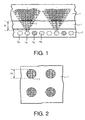
- the figure 1 represents a lighting device according to the invention. It comprises a carpet C of light-emitting diodes comprising green diodes D G emitting in a first spectral band centered on a first wavelength located in the green, blue diodes D B emitting in a second spectral band centered on a second length d wave located in the blue and red diodes D R emitting in a third spectral band centered on a third wavelength located in the red.
- the device comprises an optical blade 1 disposed above the diode mat. This blade comprises a plurality of interference filters 2 arranged in areas located above some of the red diodes at a height H.
- the filters 2 have a cut-off wavelength ⁇ C situated in the red in the vicinity of 630 nanometers so as to ensure the compatibility of the transmitted radiation by the filter with the use of night vision binoculars.
- the filters have a geometric shape with radial symmetry; the simplest form to implement is the circle as shown on the figure 2 which represents a top view of the optical filters 2. But, it is possible to use more sophisticated forms.
- the shape of the filters may consist of concentric rings or have patterns.
- the filter acts on the radiation of the red diode emitted in a solid angle of apex angle ⁇ with tan ( ⁇ ) equal to R / H.
- the rest of the radiation emitted by the red diode is not filtered as seen on the figure 1 where the radiation transmitted by the filter is represented in dark gray and the radiation transmitted directly by the diode is represented in light gray.
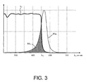
- a first flux whose spectral distribution RS F is represented in dark gray on the figure 3 is transmitted through the optical filter, a second stream whose spectral distribution is that of the diode is transmitted without having passed through the filter.
- the device also comprises above this blade a light guide 3 which ensures the mixing of light flows from different diodes so as to obtain a uniform illumination and "white".
- This guide may be a simple blade with flat and parallel faces, transparent whose thickness is sufficient to ensure proper mixing.
- This guide may be a more sophisticated component comprising, for example, prismatic parts for obtaining homogeneity of luminous flux in a smaller footprint than that of a single blade.
- the device is able to operate both day and night. It comprises electronic control means ensuring both modes of operation. In day mode, the electronic control means controls the unfiltered blue, green and red diodes which are lit. In night mode, the blue LEDs, the green LEDs and only the filtered red LEDs are lit.
- the control means make it possible to adjust the luminous flux emitted either by varying the electrical intensity flowing in the diodes, or by varying the firing times of the diodes, PWM technique for "Pulse Width Modulator"
Abstract
Description
Le domaine de l'invention est celui des dispositifs d'éclairage compatibles « NVG » à diodes électroluminescentes pour écrans plats de visualisations tels que les matrices à cristaux liquides. On entend par éclairage compatible « NVG », un éclairage pouvant être utilisé avec des jumelles à amplification de lumière dites « NVG » pour « Night Vision Goggle», c'est-à-dire que l'éclairage ne sature pas les systèmes d'amplification des jumelles. Les dispositifs d'éclairages sont également connus sous la terminologie anglo-saxonne de « backlighting ». Les écrans plats ont de multiples applications, ils peuvent être utilisés, par exemple, pour réaliser des dispositifs d'affichage de tableaux de bord d'aéronefs.The field of the invention is that of "NVG" compatible light-emitting diodes for flat displays of visualizations such as liquid crystal matrices. "NVG" compatible lighting means lighting that can be used with "NVG" light amplification binoculars for "Night Vision Goggle", that is, the lighting does not saturate the lighting systems. amplification binoculars. Lighting devices are also known in the Anglo-Saxon terminology of "backlighting". Flat screens have multiple applications, they can be used, for example, to make devices for displaying aircraft dashboards.
L'éclairage des écrans plats à cristaux liquides a été initialement assuré par des tubes fluorescents, généralement de type CCFL, acronyme signifiant « Cold Cathod Fluorescent Light ». Cette technologie présente un certain nombre d'inconvénients. On citera essentiellement les problèmes d'obsolescence, la nécessité d'une alimentation électrique à haute tension, une consommation électrique élevée et des problèmes de compatibilité avec les nouvelles normes environnementales dites RoHS, acronyme signifiant : « Restriction Of the use of certain Hazardous substance in electrical and electronic equipment ». Pour être compatibles « NVG » et ne pas saturer les dispositifs d'amplification des jumelles, les éclairages à tubes fluorescents comportent des filtres optiques, ce qui ajoute une difficulté supplémentaire.LCD flat panel lighting was initially provided by fluorescent tubes, generally of the CCFL type, which stands for Cold Cathod Fluorescent Light. This technology has a number of disadvantages. These include obsolescence issues, the need for a high-voltage power supply, high power consumption, and compatibility issues with the new RoHS environmental standards, which stands for "Restriction of Use of Certain Hazardous Substances". electrical and electronic equipment ". To be "NVG" compatible and not to saturate binocular amplification devices, fluorescent tube lights include optical filters, which adds additional difficulty.
Les tubes fluorescents sont actuellement concurrencés par les éclairages à diodes électroluminescentes qui ne présentent pas certains des inconvénients précédents. Les diodes sont des sources de lumière ponctuelles ou quasi-ponctuelles émettant dans un cône d'émission donné, la plupart des diodes ayant un profil d'émission dit lambertien. Pour éclairer un écran plat de façon homogène à partir de sources ponctuelles, plusieurs dispositifs optiques ont été proposés. Ainsi, le dispositif d'éclairage peut être constitué d'un « tapis » de diodes électroluminescentes disposées sous l'écran. Généralement, on utilise trois types de diodes émettant dans trois bandes spectrales différentes dans le spectre visible de façon que le mélange des faisceaux émis donne une lumière blanche. Généralement, les diodes émettent dans le rouge, le vert et le bleu.Fluorescent tubes are currently competing with light emitting diode lights that do not have some of the above disadvantages. The diodes are point or quasi-point light sources emitting in a given emission cone, most of the diodes having a Lambertian emission profile. To illuminate a flat screen evenly from point sources, several optical devices have been proposed. Thus, the lighting device may consist of a "carpet" of light-emitting diodes arranged under the screen. Generally, three types of diodes emitting in three different spectral bands in the visible spectrum are used so that the mixture of emitted beams gives a white light. Generally, the diodes emit in red, green and blue.
On sait que les dispositifs d'amplification des jumelles de vision de nuit ont un coefficient d'amplification important dans une bande spectrale commençant à l'extrémité rouge du spectre visible, autour de 650 nanomètres et finissant dans l'infrarouge proche, autour de 930 nanomètres. Les diodes émettant dans le vert ou dans le bleu sont naturellement compatibles « NVG ", leur émission dans le rouge ou le proche infrarouge étant très faible ou inexistante. Il n'en est pas de même des diodes émettant dans le rouge qui doivent être filtrées de façon à ne pas saturer les jumelles. Le problème du filtrage n'est pas simple. En effet, il doit être suffisant pour assurer la compatibilité « NVG » et ne pas être trop important pour que la colorimétrie reste correcte, c'est-à-dire pour que la couleur rouge reste rouge et ne devienne pas ou trop orangée ou trop sombre. La compatibilité « NVG » fait l'objet de normes internationales comme la norme MIL STD 3009, particulièrement strictes. Les problèmes de colorimétrie sont très importants dans la mesure où, dans un grand nombre d'applications, le rouge est associé aux alarmes et doit être parfaitement identifié comme tel. Il faut également noter que la sensibilité de l'oeil décroît très rapidement dans la partie rouge du spectre, compliquant encore la réalisation du filtre. Enfin, tous les types de diodes rouges n'ont pas strictement la même répartition spectrale. Ainsi, chaque changement de diode s'accompagne d'une nouvelle optimisation des moyens de filtrage.Night vision binocular amplification devices are known to have a significant amplification coefficient in a spectral band starting at the red end of the visible spectrum, around 650 nanometers and ending in the near infrared, around 930 nanometers. The diodes emitting in the green or in the blue are naturally compatible "NVG", their emission in the red or the near infrared being very weak or non-existent It is not the same of the diodes emitting in the red which must be filtered so that the binoculars are not saturated The problem of filtering is not simple: it must be sufficient to ensure NVG compatibility and not be too important for the colorimetry to remain correct. to make sure that the red color stays red and does not become too orange or too dark NVG compatibility is subject to international standards such as the MIL STD 3009, which are particularly stringent. since in a large number of applications red is associated with the alarms and must be clearly identified as such, it should also be noted that the sensitivity of the eye decreases very rapidly. in the red part of the spectrum, further complicating the implementation of the filter. Finally, not all types of red diodes have exactly the same spectral distribution. Thus, each diode change is accompanied by a new optimization of the filtering means.
Pour pallier ces différents inconvénients, le dispositif selon l'invention comporte un filtre interférentiel disposé au-dessus de la diode, le filtre ayant un diamètre déterminé. Ainsi, pour assurer la compatibilité « NVG » et maintenir une colorimétrie satisfaisante, on dispose de deux types de paramètres, les paramètres photométriques du filtre et d'autre part les paramètres géométriques qui permettent de « doser » la quantité de lumière rouge filtrée par le filtre optique.To overcome these various disadvantages, the device according to the invention comprises an interference filter disposed above the diode, the filter having a determined diameter. Thus, to ensure "NVG" compatibility and maintain a satisfactory colorimetry, two types of parameters are available, the photometric parameters of the filter and, on the other hand, the geometric parameters that make it possible to "dose" the amount of red light filtered by the optical filter.
Plus précisément, l'invention a pour objet un dispositif d'éclairage selon la revendication 1More specifically, the subject of the invention is a lighting device according to claim 1
Avantageusement, le dispositif comporte des moyens de commande assurant deux modes de fonctionnement dits de jour et de nuit, en mode de jour, les diodes bleues, vertes et rouges sont allumées, en mode de nuit, les diodes bleues, les diodes vertes et uniquement les diodes rouges filtrées sont allumées.Advantageously, the device comprises control means ensuring two so-called day and night modes of operation, in day mode, the blue, green and red diodes are lit, in night mode, the blue diodes, the green diodes and only the filtered red LEDs are lit.
L'invention sera mieux comprise et d'autres avantages apparaîtront à la lecture de la description qui va suivre donnée à titre non limitatif et grâce aux figures annexées parmi lesquelles :
- La
figure 1 représente une vue en coupe d'un dispositif selon l'invention ; - La
figure 2 représente une vue de dessus des filtres optiques ; - La
figure 3 représente la transmission du filtre optique en fonction de la longueur d'onde et la répartition spectrale du spectre d'émission d'une diode rouge.
- The
figure 1 represents a sectional view of a device according to the invention; - The
figure 2 represents a view from above of the optical filters; - The
figure 3 represents the transmission of the optical filter as a function of the wavelength and the spectral distribution of the emission spectrum of a red diode.
La
Comme indiqué sur la
Les filtres ont une forme géométrique à symétrie radiale ; la forme la plus simple à mettre en oeuvre est le cercle comme indiqué sur la
Sur la
A titre d'exemple, pour une diode ayant les caractéristiques suivantes :
- Largeur d'indicatrice d'intensité lumineuse : 40 degrés à mi-hauteur,
- Spectre de la diode ayant un pic d'émission centré sur 630 nanomètres et une longueur d'onde dominante comprise entre 610 et 615 nanomètres ;
- Le filtre ayant une longueur d'onde de coupure située dans le rouge au voisinage de 630 nanomètres, le rayon du filtre étant de l'ordre de 6 millimètres, la hauteur du filtre au-dessus de la diode de l'ordre de 15 millimètres,
- La compatibilité de la diode filtrée avec la norme MIL-STD-3009 est assurée et les coordonnées colorimétriques de la lumière émise par la diode filtrée à travers la matrice LCD de l'écran sont, en coordonnées (u', v') selon la norme CIE 1976, telles que u' dépasse 0.42. On considère généralement que lorsque la valeur de la coordonnées u' est supérieure à cette valeur, la couleur apparaît rouge, ce qui est bien le but recherché.
- Luminous intensity indicator width: 40 degrees at mid-height,
- Spectrum of the diode having an emission peak centered on 630 nanometers and a dominant wavelength between 610 and 615 nanometers;
- The filter having a cut-off wavelength located in the red in the vicinity of 630 nanometers, the radius of the filter being of the order of 6 millimeters, the height of the filter above the diode of the order of 15 millimeters ,
- The compatibility of the filtered diode with the MIL-STD-3009 standard is ensured and the colorimetric coordinates of the light emitted by the filtered diode through the LCD matrix of the screen are, in coordinates (u ', v') according to the CIE 1976 standard, such that u 'exceeds 0.42. It is generally considered that when the value of the coordinate u 'is greater than this value, the color appears red, which is the goal.
Le dispositif comporte également au-dessus de cette lame un guide de lumière 3 qui assure le mélange des flux lumineux provenant des différentes diodes de façon à obtenir un éclairage uniforme et « blanc ». Ce guide peut être une simple lame à faces planes et parallèles, transparente dont l'épaisseur est suffisante pour assurer un mélange correct. Ce guide peut être un composant plus sophistiqué comprenant, par exemple, des parties prismatiques permettant d'obtenir une homogénéité de flux lumineux dans un encombrement plus faible que celui d'une lame simple.The device also comprises above this blade a
Le dispositif est apte à fonctionner de jour comme de nuit. Il comporte des moyens de commande électroniques assurant les deux modes de fonctionnement. En mode de jour, les moyens de commande électroniques pilotent les diodes bleues, vertes et rouges non filtrées qui sont allumées. En mode de nuit, les diodes bleues, les diodes vertes et uniquement les diodes rouges filtrées sont allumées. Bien entendu, les moyens de commande permettent de régler les flux lumineux émis soit en faisant varier l'intensité électrique circulant dans les diodes, soit en faisant varier les temps d'allumage des diodes, technique dite PWM pour « Pulse Width Modulator »The device is able to operate both day and night. It comprises electronic control means ensuring both modes of operation. In day mode, the electronic control means controls the unfiltered blue, green and red diodes which are lit. In night mode, the blue LEDs, the green LEDs and only the filtered red LEDs are lit. Of course, the control means make it possible to adjust the luminous flux emitted either by varying the electrical intensity flowing in the diodes, or by varying the firing times of the diodes, PWM technique for "Pulse Width Modulator"
Claims (2)
- A lighting device compatible with the use of night vision goggles comprising a light intensifier, said device comprising at least one layer (C) of diodes comprising three types of light-emitting diodes, referred to as green diodes (DG), blue diodes (DB) and red diodes (DR), emitting in three different spectral bands respectively centred on a first wavelength located in the green, a second wavelength located in the blue, a third wavelength located in the red, characterised in that the device comprises an optical plate (1) disposed above the layer of diodes, the zones of the optical plate that are located at a height (H) above certain ones of the red diodes comprising an interference filter (2), the optical transmission of which has a cut-off wavelength located in the red in the vicinity of 630 nanometres, said height (H) and the geometric shape of said interference filter (2) being selected so as to distribute the light emitted by the red diodes between a part transmitted through the interference filter (2) and a part that does not pass through said interference filter (2).
- The lighting device according to claim 1, characterised in that it comprises control means providing two operating modes, referred to as daytime and night-time modes, wherein in daytime mode the blue, green and red diodes are lit and in night-time mode the blue, green and only the filtered red diodes are lit.
Applications Claiming Priority (1)
| Application Number | Priority Date | Filing Date | Title |
|---|---|---|---|
| FR0900528A FR2942023B1 (en) | 2009-02-06 | 2009-02-06 | COMPATIBLE ELECTROLUMINESCENT DIODE LIGHTING DEVICE. |
Publications (2)
| Publication Number | Publication Date |
|---|---|
| EP2216675A1 EP2216675A1 (en) | 2010-08-11 |
| EP2216675B1 true EP2216675B1 (en) | 2011-12-28 |
Family
ID=41320086
Family Applications (1)
| Application Number | Title | Priority Date | Filing Date |
|---|---|---|---|
| EP10152142A Active EP2216675B1 (en) | 2009-02-06 | 2010-01-29 | Night vision goggle compatible lighting device with light-emitting diodes |
Country Status (5)
| Country | Link |
|---|---|
| US (1) | US8292459B2 (en) |
| EP (1) | EP2216675B1 (en) |
| AT (1) | ATE539373T1 (en) |
| CA (1) | CA2692088A1 (en) |
| FR (1) | FR2942023B1 (en) |
Families Citing this family (5)
| Publication number | Priority date | Publication date | Assignee | Title |
|---|---|---|---|---|
| WO2012080934A1 (en) * | 2010-12-17 | 2012-06-21 | Koninklijke Philips Electronics N.V. | Illumination system with light source, radiation converting element and filter |
| GB2496878B (en) * | 2011-11-24 | 2018-09-19 | Fenn Night Vision Ltd | Ground use night vision device apparatus |
| FR3025291B1 (en) | 2014-08-29 | 2016-12-30 | Thales Sa | LIGHT EMITTING DIODE LIGHTING DEVICE HAVING A LIGHT GUIDE AND A COMPATIBLE LIGHTING OF THE USE OF NIGHT VISION BINOCULARS |
| FR3025287B1 (en) | 2014-08-29 | 2016-12-30 | Thales Sa | LIGHT EMITTING DIODE LIGHTING DEVICE COMPRISING LIGHTING COMPATIBLE WITH THE USE OF NIGHT VISION BINOCULARS AND COMPRISING A LIGHT GUIDE |
| JP2023179933A (en) * | 2022-06-08 | 2023-12-20 | 株式会社ジャパンディスプレイ | display device |
Family Cites Families (6)
| Publication number | Priority date | Publication date | Assignee | Title |
|---|---|---|---|---|
| US5262880A (en) * | 1990-04-26 | 1993-11-16 | Ois Optical Imaging Systems, Inc. | Night vision goggle compatible liquid crystal display device |
| US5161879A (en) * | 1991-04-10 | 1992-11-10 | Mcdermott Kevin | Flashlight for covert applications |
| JPH06175601A (en) * | 1992-12-04 | 1994-06-24 | Japan Aviation Electron Ind Ltd | Color liquid crystal display device dealing with ngv |
| CN1993826B (en) * | 2004-08-06 | 2010-06-23 | 皇家飞利浦电子股份有限公司 | LED light system |
| US7326179B1 (en) * | 2004-12-02 | 2008-02-05 | Juan Enrique Cienfuegos | Illuminated display system and method of use |
| US7525611B2 (en) * | 2006-01-24 | 2009-04-28 | Astronautics Corporation Of America | Night vision compatible display backlight |
-
2009
- 2009-02-06 FR FR0900528A patent/FR2942023B1/en not_active Expired - Fee Related
-
2010
- 2010-01-29 EP EP10152142A patent/EP2216675B1/en active Active
- 2010-01-29 AT AT10152142T patent/ATE539373T1/en active
- 2010-02-03 US US12/699,161 patent/US8292459B2/en active Active
- 2010-02-03 CA CA2692088A patent/CA2692088A1/en not_active Abandoned
Also Published As
| Publication number | Publication date |
|---|---|
| CA2692088A1 (en) | 2010-08-06 |
| EP2216675A1 (en) | 2010-08-11 |
| FR2942023B1 (en) | 2012-07-13 |
| ATE539373T1 (en) | 2012-01-15 |
| US8292459B2 (en) | 2012-10-23 |
| US20100201288A1 (en) | 2010-08-12 |
| FR2942023A1 (en) | 2010-08-13 |
Similar Documents
| Publication | Publication Date | Title |
|---|---|---|
| CA2581593C (en) | Illuminated light box with light-emitting diodes | |
| EP2216675B1 (en) | Night vision goggle compatible lighting device with light-emitting diodes | |
| FR2678415A1 (en) | DISPLAY DEVICE PROVIDED WITH FILTERS. | |
| FR2854252A1 (en) | Lighting photometric/colorimetric characteristics control device for aircraft, has optoelectronic devices for measuring characteristics of diodes of lamp box where devices include assembly for isolating external light | |
| EP3079938A2 (en) | Lighting device | |
| FR3061538A1 (en) | LIGHTING DEVICE FOR A VEHICLE COMBINING TWO LIGHT SOURCES | |
| EP2781409A1 (en) | Multifunctional lighting and/or signalling system | |
| EP3507542B1 (en) | Lighting and/or signalling device, in particular for an automotive vehicle | |
| EP3025094A1 (en) | Lighting device | |
| EP0677970B1 (en) | Light box for light valve | |
| EP4154047A1 (en) | Scanned light beam video projection system and method, automotive vehicle head-up display and adaptive lighting device using such a system | |
| FR2888002A1 (en) | BACKLIGHT UNIT AND LIQUID CRYSTAL DISPLAY DEVICE PROVIDED WITH THIS UNIT | |
| FR3011615A1 (en) | ||
| EP3186548A1 (en) | Light-emitting diode lighting device comprising a light compatible with the use of night vision binoculars and comprising a light guide | |
| FR2727559A1 (en) | Dashboard panel display device for vehicles | |
| EP3653929A1 (en) | Lighting device compatible with night vision device(s) | |
| FR2843792A1 (en) | High-luminance light box used to illuminate display screens with optical valves such as liquid-crystal matrix screens, has fluorescent tubes spread out in many superposed layers | |
| CA2959658C (en) | Light-emitting diode lighting device comprising a light guide and a light compatible with the use of night vision binoculars | |
| WO2006013163A1 (en) | Illuminating source for liquid crystal display | |
| FR3082011A1 (en) | IMAGE GENERATION DEVICE AND HEAD-UP DISPLAY COMPRISING SUCH A DEVICE | |
| FR3054293B1 (en) | ILLUMINATING AND / OR SIGNALING DEVICE FOR A VEHICLE WITH A LIGHT EFFECT | |
| FR2607247A1 (en) | INDICATORS READABLE AS WELL WITH NIGHT VISION GLASSES AS IN SUN LIGHT | |
| FR3005493A1 (en) | LIGHTING SYSTEM EMITTING DIFFERENT LIGHT RADIATION | |
| FR2804279A1 (en) | ULTRA-PURPLE LIGHTING DEVICE AND ITS APPLICATION TO A D4AERONEF COCKPIT | |
| FR3077649A1 (en) | IMAGE GENERATING DEVICE AND HEAD DISPLAY COMPRISING SUCH A DEVICE |
Legal Events
| Date | Code | Title | Description |
|---|---|---|---|
| PUAI | Public reference made under article 153(3) epc to a published international application that has entered the european phase |
Free format text: ORIGINAL CODE: 0009012 |
|
| AK | Designated contracting states |
Kind code of ref document: A1 Designated state(s): AT BE BG CH CY CZ DE DK EE ES FI FR GB GR HR HU IE IS IT LI LT LU LV MC MK MT NL NO PL PT RO SE SI SK SM TR |
|
| AX | Request for extension of the european patent |
Extension state: AL BA RS |
|
| 17P | Request for examination filed |
Effective date: 20110207 |
|
| GRAP | Despatch of communication of intention to grant a patent |
Free format text: ORIGINAL CODE: EPIDOSNIGR1 |
|
| RIC1 | Information provided on ipc code assigned before grant |
Ipc: G02F 1/13357 20060101AFI20110628BHEP |
|
| RTI1 | Title (correction) |
Free format text: NIGHT VISION GOGGLE COMPATIBLE LIGHTING DEVICE WITH LIGHT-EMITTING DIODES |
|
| RIN1 | Information on inventor provided before grant (corrected) |
Inventor name: MOZER, LAURENT Inventor name: PETITDEMANGE, ARNAUD Inventor name: ROLS, M. OLIVIER |
|
| GRAS | Grant fee paid |
Free format text: ORIGINAL CODE: EPIDOSNIGR3 |
|
| GRAA | (expected) grant |
Free format text: ORIGINAL CODE: 0009210 |
|
| AK | Designated contracting states |
Kind code of ref document: B1 Designated state(s): AT BE BG CH CY CZ DE DK EE ES FI FR GB GR HR HU IE IS IT LI LT LU LV MC MK MT NL NO PL PT RO SE SI SK SM TR |
|
| REG | Reference to a national code |
Ref country code: GB Ref legal event code: FG4D Free format text: NOT ENGLISH |
|
| REG | Reference to a national code |
Ref country code: CH Ref legal event code: EP |
|
| REG | Reference to a national code |
Ref country code: AT Ref legal event code: REF Ref document number: 539373 Country of ref document: AT Kind code of ref document: T Effective date: 20120115 |
|
| REG | Reference to a national code |
Ref country code: IE Ref legal event code: FG4D |
|
| REG | Reference to a national code |
Ref country code: DE Ref legal event code: R096 Ref document number: 602010000539 Country of ref document: DE Effective date: 20120308 |
|
| REG | Reference to a national code |
Ref country code: NL Ref legal event code: VDEP Effective date: 20111228 |
|
| PG25 | Lapsed in a contracting state [announced via postgrant information from national office to epo] |
Ref country code: NO Free format text: LAPSE BECAUSE OF FAILURE TO SUBMIT A TRANSLATION OF THE DESCRIPTION OR TO PAY THE FEE WITHIN THE PRESCRIBED TIME-LIMIT Effective date: 20120328 Ref country code: LT Free format text: LAPSE BECAUSE OF FAILURE TO SUBMIT A TRANSLATION OF THE DESCRIPTION OR TO PAY THE FEE WITHIN THE PRESCRIBED TIME-LIMIT Effective date: 20111228 |
|
| LTIE | Lt: invalidation of european patent or patent extension |
Effective date: 20111228 |
|
| PG25 | Lapsed in a contracting state [announced via postgrant information from national office to epo] |
Ref country code: GR Free format text: LAPSE BECAUSE OF FAILURE TO SUBMIT A TRANSLATION OF THE DESCRIPTION OR TO PAY THE FEE WITHIN THE PRESCRIBED TIME-LIMIT Effective date: 20120329 Ref country code: HR Free format text: LAPSE BECAUSE OF FAILURE TO SUBMIT A TRANSLATION OF THE DESCRIPTION OR TO PAY THE FEE WITHIN THE PRESCRIBED TIME-LIMIT Effective date: 20111228 Ref country code: SE Free format text: LAPSE BECAUSE OF FAILURE TO SUBMIT A TRANSLATION OF THE DESCRIPTION OR TO PAY THE FEE WITHIN THE PRESCRIBED TIME-LIMIT Effective date: 20111228 Ref country code: SI Free format text: LAPSE BECAUSE OF FAILURE TO SUBMIT A TRANSLATION OF THE DESCRIPTION OR TO PAY THE FEE WITHIN THE PRESCRIBED TIME-LIMIT Effective date: 20111228 Ref country code: LV Free format text: LAPSE BECAUSE OF FAILURE TO SUBMIT A TRANSLATION OF THE DESCRIPTION OR TO PAY THE FEE WITHIN THE PRESCRIBED TIME-LIMIT Effective date: 20111228 |
|
| PG25 | Lapsed in a contracting state [announced via postgrant information from national office to epo] |
Ref country code: CY Free format text: LAPSE BECAUSE OF FAILURE TO SUBMIT A TRANSLATION OF THE DESCRIPTION OR TO PAY THE FEE WITHIN THE PRESCRIBED TIME-LIMIT Effective date: 20111228 |
|
| REG | Reference to a national code |
Ref country code: IE Ref legal event code: FD4D |
|
| BERE | Be: lapsed |
Owner name: THALES Effective date: 20120131 |
|
| PG25 | Lapsed in a contracting state [announced via postgrant information from national office to epo] |
Ref country code: IE Free format text: LAPSE BECAUSE OF FAILURE TO SUBMIT A TRANSLATION OF THE DESCRIPTION OR TO PAY THE FEE WITHIN THE PRESCRIBED TIME-LIMIT Effective date: 20111228 Ref country code: BG Free format text: LAPSE BECAUSE OF FAILURE TO SUBMIT A TRANSLATION OF THE DESCRIPTION OR TO PAY THE FEE WITHIN THE PRESCRIBED TIME-LIMIT Effective date: 20120328 Ref country code: EE Free format text: LAPSE BECAUSE OF FAILURE TO SUBMIT A TRANSLATION OF THE DESCRIPTION OR TO PAY THE FEE WITHIN THE PRESCRIBED TIME-LIMIT Effective date: 20111228 Ref country code: CZ Free format text: LAPSE BECAUSE OF FAILURE TO SUBMIT A TRANSLATION OF THE DESCRIPTION OR TO PAY THE FEE WITHIN THE PRESCRIBED TIME-LIMIT Effective date: 20111228 Ref country code: SK Free format text: LAPSE BECAUSE OF FAILURE TO SUBMIT A TRANSLATION OF THE DESCRIPTION OR TO PAY THE FEE WITHIN THE PRESCRIBED TIME-LIMIT Effective date: 20111228 Ref country code: IS Free format text: LAPSE BECAUSE OF FAILURE TO SUBMIT A TRANSLATION OF THE DESCRIPTION OR TO PAY THE FEE WITHIN THE PRESCRIBED TIME-LIMIT Effective date: 20120428 Ref country code: NL Free format text: LAPSE BECAUSE OF FAILURE TO SUBMIT A TRANSLATION OF THE DESCRIPTION OR TO PAY THE FEE WITHIN THE PRESCRIBED TIME-LIMIT Effective date: 20111228 |
|
| PG25 | Lapsed in a contracting state [announced via postgrant information from national office to epo] |
Ref country code: RO Free format text: LAPSE BECAUSE OF FAILURE TO SUBMIT A TRANSLATION OF THE DESCRIPTION OR TO PAY THE FEE WITHIN THE PRESCRIBED TIME-LIMIT Effective date: 20111228 Ref country code: MC Free format text: LAPSE BECAUSE OF NON-PAYMENT OF DUE FEES Effective date: 20120131 Ref country code: PL Free format text: LAPSE BECAUSE OF FAILURE TO SUBMIT A TRANSLATION OF THE DESCRIPTION OR TO PAY THE FEE WITHIN THE PRESCRIBED TIME-LIMIT Effective date: 20111228 Ref country code: PT Free format text: LAPSE BECAUSE OF FAILURE TO SUBMIT A TRANSLATION OF THE DESCRIPTION OR TO PAY THE FEE WITHIN THE PRESCRIBED TIME-LIMIT Effective date: 20120430 |
|
| REG | Reference to a national code |
Ref country code: AT Ref legal event code: MK05 Ref document number: 539373 Country of ref document: AT Kind code of ref document: T Effective date: 20111228 |
|
| PG25 | Lapsed in a contracting state [announced via postgrant information from national office to epo] |
Ref country code: DK Free format text: LAPSE BECAUSE OF FAILURE TO SUBMIT A TRANSLATION OF THE DESCRIPTION OR TO PAY THE FEE WITHIN THE PRESCRIBED TIME-LIMIT Effective date: 20111228 |
|
| PLBE | No opposition filed within time limit |
Free format text: ORIGINAL CODE: 0009261 |
|
| STAA | Information on the status of an ep patent application or granted ep patent |
Free format text: STATUS: NO OPPOSITION FILED WITHIN TIME LIMIT |
|
| 26N | No opposition filed |
Effective date: 20121001 |
|
| PG25 | Lapsed in a contracting state [announced via postgrant information from national office to epo] |
Ref country code: BE Free format text: LAPSE BECAUSE OF NON-PAYMENT OF DUE FEES Effective date: 20120131 |
|
| REG | Reference to a national code |
Ref country code: DE Ref legal event code: R097 Ref document number: 602010000539 Country of ref document: DE Effective date: 20121001 |
|
| PG25 | Lapsed in a contracting state [announced via postgrant information from national office to epo] |
Ref country code: AT Free format text: LAPSE BECAUSE OF FAILURE TO SUBMIT A TRANSLATION OF THE DESCRIPTION OR TO PAY THE FEE WITHIN THE PRESCRIBED TIME-LIMIT Effective date: 20111228 |
|
| PG25 | Lapsed in a contracting state [announced via postgrant information from national office to epo] |
Ref country code: MK Free format text: LAPSE BECAUSE OF FAILURE TO SUBMIT A TRANSLATION OF THE DESCRIPTION OR TO PAY THE FEE WITHIN THE PRESCRIBED TIME-LIMIT Effective date: 20111228 |
|
| PG25 | Lapsed in a contracting state [announced via postgrant information from national office to epo] |
Ref country code: ES Free format text: LAPSE BECAUSE OF FAILURE TO SUBMIT A TRANSLATION OF THE DESCRIPTION OR TO PAY THE FEE WITHIN THE PRESCRIBED TIME-LIMIT Effective date: 20120408 |
|
| PG25 | Lapsed in a contracting state [announced via postgrant information from national office to epo] |
Ref country code: FI Free format text: LAPSE BECAUSE OF FAILURE TO SUBMIT A TRANSLATION OF THE DESCRIPTION OR TO PAY THE FEE WITHIN THE PRESCRIBED TIME-LIMIT Effective date: 20111228 |
|
| PG25 | Lapsed in a contracting state [announced via postgrant information from national office to epo] |
Ref country code: MT Free format text: LAPSE BECAUSE OF FAILURE TO SUBMIT A TRANSLATION OF THE DESCRIPTION OR TO PAY THE FEE WITHIN THE PRESCRIBED TIME-LIMIT Effective date: 20111228 |
|
| PG25 | Lapsed in a contracting state [announced via postgrant information from national office to epo] |
Ref country code: TR Free format text: LAPSE BECAUSE OF FAILURE TO SUBMIT A TRANSLATION OF THE DESCRIPTION OR TO PAY THE FEE WITHIN THE PRESCRIBED TIME-LIMIT Effective date: 20111228 |
|
| PG25 | Lapsed in a contracting state [announced via postgrant information from national office to epo] |
Ref country code: LU Free format text: LAPSE BECAUSE OF NON-PAYMENT OF DUE FEES Effective date: 20120129 Ref country code: SM Free format text: LAPSE BECAUSE OF FAILURE TO SUBMIT A TRANSLATION OF THE DESCRIPTION OR TO PAY THE FEE WITHIN THE PRESCRIBED TIME-LIMIT Effective date: 20111228 |
|
| PG25 | Lapsed in a contracting state [announced via postgrant information from national office to epo] |
Ref country code: HU Free format text: LAPSE BECAUSE OF FAILURE TO SUBMIT A TRANSLATION OF THE DESCRIPTION OR TO PAY THE FEE WITHIN THE PRESCRIBED TIME-LIMIT Effective date: 20100129 |
|
| REG | Reference to a national code |
Ref country code: CH Ref legal event code: PL |
|
| PG25 | Lapsed in a contracting state [announced via postgrant information from national office to epo] |
Ref country code: CH Free format text: LAPSE BECAUSE OF NON-PAYMENT OF DUE FEES Effective date: 20140131 Ref country code: LI Free format text: LAPSE BECAUSE OF NON-PAYMENT OF DUE FEES Effective date: 20140131 |
|
| REG | Reference to a national code |
Ref country code: FR Ref legal event code: PLFP Year of fee payment: 7 |
|
| PGFP | Annual fee paid to national office [announced via postgrant information from national office to epo] |
Ref country code: DE Payment date: 20160127 Year of fee payment: 7 Ref country code: IT Payment date: 20160127 Year of fee payment: 7 |
|
| PGFP | Annual fee paid to national office [announced via postgrant information from national office to epo] |
Ref country code: GB Payment date: 20160127 Year of fee payment: 7 |
|
| REG | Reference to a national code |
Ref country code: FR Ref legal event code: PLFP Year of fee payment: 8 |
|
| REG | Reference to a national code |
Ref country code: DE Ref legal event code: R119 Ref document number: 602010000539 Country of ref document: DE |
|
| GBPC | Gb: european patent ceased through non-payment of renewal fee |
Effective date: 20170129 |
|
| PG25 | Lapsed in a contracting state [announced via postgrant information from national office to epo] |
Ref country code: DE Free format text: LAPSE BECAUSE OF NON-PAYMENT OF DUE FEES Effective date: 20170801 Ref country code: GB Free format text: LAPSE BECAUSE OF NON-PAYMENT OF DUE FEES Effective date: 20170129 |
|
| REG | Reference to a national code |
Ref country code: FR Ref legal event code: PLFP Year of fee payment: 9 |
|
| PG25 | Lapsed in a contracting state [announced via postgrant information from national office to epo] |
Ref country code: IT Free format text: LAPSE BECAUSE OF NON-PAYMENT OF DUE FEES Effective date: 20170129 |
|
| P01 | Opt-out of the competence of the unified patent court (upc) registered |
Effective date: 20230427 |
|
| PGFP | Annual fee paid to national office [announced via postgrant information from national office to epo] |
Ref country code: FR Payment date: 20231222 Year of fee payment: 15 |