EP2216666A1 - Cable and method for manufacturing the same - Google Patents
Cable and method for manufacturing the same Download PDFInfo
- Publication number
- EP2216666A1 EP2216666A1 EP09001665A EP09001665A EP2216666A1 EP 2216666 A1 EP2216666 A1 EP 2216666A1 EP 09001665 A EP09001665 A EP 09001665A EP 09001665 A EP09001665 A EP 09001665A EP 2216666 A1 EP2216666 A1 EP 2216666A1
- Authority
- EP
- European Patent Office
- Prior art keywords
- cable
- strength members
- loop
- pulling member
- jacket
- Prior art date
- Legal status (The legal status is an assumption and is not a legal conclusion. Google has not performed a legal analysis and makes no representation as to the accuracy of the status listed.)
- Withdrawn
Links
- 238000000034 method Methods 0.000 title claims description 12
- 238000004519 manufacturing process Methods 0.000 title claims description 11
- 238000009434 installation Methods 0.000 claims abstract description 23
- 230000005540 biological transmission Effects 0.000 claims abstract description 18
- 239000013307 optical fiber Substances 0.000 claims description 33
- 230000003287 optical effect Effects 0.000 claims description 17
- 239000002991 molded plastic Substances 0.000 claims description 6
- 238000005520 cutting process Methods 0.000 claims description 4
- 238000009826 distribution Methods 0.000 description 9
- 239000000835 fiber Substances 0.000 description 8
- RYGMFSIKBFXOCR-UHFFFAOYSA-N Copper Chemical compound [Cu] RYGMFSIKBFXOCR-UHFFFAOYSA-N 0.000 description 2
- 229910052802 copper Inorganic materials 0.000 description 2
- 239000010949 copper Substances 0.000 description 2
- 238000005516 engineering process Methods 0.000 description 2
- 238000001125 extrusion Methods 0.000 description 2
- 238000001746 injection moulding Methods 0.000 description 2
- 239000000463 material Substances 0.000 description 2
- 229920000271 Kevlar® Polymers 0.000 description 1
- 238000004891 communication Methods 0.000 description 1
- 230000001419 dependent effect Effects 0.000 description 1
- 238000011161 development Methods 0.000 description 1
- 230000018109 developmental process Effects 0.000 description 1
- 239000003292 glue Substances 0.000 description 1
- 239000004761 kevlar Substances 0.000 description 1
- 239000002184 metal Substances 0.000 description 1
- 229910052751 metal Inorganic materials 0.000 description 1
- 239000004033 plastic Substances 0.000 description 1
- AFJYYKSVHJGXSN-KAJWKRCWSA-N selamectin Chemical compound O1[C@@H](C)[C@H](O)[C@@H](OC)C[C@@H]1O[C@@H]1C(/C)=C/C[C@@H](O[C@]2(O[C@@H]([C@@H](C)CC2)C2CCCCC2)C2)C[C@@H]2OC(=O)[C@@H]([C@]23O)C=C(C)C(=N\O)/[C@H]3OC\C2=C/C=C/[C@@H]1C AFJYYKSVHJGXSN-KAJWKRCWSA-N 0.000 description 1
Images



Classifications
-
- G—PHYSICS
- G02—OPTICS
- G02B—OPTICAL ELEMENTS, SYSTEMS OR APPARATUS
- G02B6/00—Light guides; Structural details of arrangements comprising light guides and other optical elements, e.g. couplings
- G02B6/46—Processes or apparatus adapted for installing or repairing optical fibres or optical cables
- G02B6/47—Installation in buildings
- G02B6/475—Mechanical aspects of installing cables in ducts or the like for buildings
-
- G—PHYSICS
- G02—OPTICS
- G02B—OPTICAL ELEMENTS, SYSTEMS OR APPARATUS
- G02B6/00—Light guides; Structural details of arrangements comprising light guides and other optical elements, e.g. couplings
- G02B6/44—Mechanical structures for providing tensile strength and external protection for fibres, e.g. optical transmission cables
- G02B6/4439—Auxiliary devices
- G02B6/4471—Terminating devices ; Cable clamps
- G02B6/4472—Manifolds
Definitions
- a cable, especially an optical cable, with a pulling member is described. Further on, methods for manufacturing the cable with a pulling member are described.
- optical cables In the world of the ever-increasing need for broadband bandwidth optical cables have become the main part of telecommunication networks.
- Optical cables can transmit voice signals, data signals and video signals for very long distances with very high speed.
- Developments of optic telecommunication networks allow the connection of the end user directly to the optical fiber.
- This kind of network technology known as FTTH technology (fiber to the home) requires extending an "all optical" communication network closer to the subscribers.
- FTTH technology fiber to the home
- telecommunication networks include large number distribution points from a distribution cable to an end user or subscriber.
- One of the key parts of the FTTH network is the last mile connection which often is an indoor installation.
- Different kind of buildings like multi dwelling units and block of flats require complicated cabling systems which might mean that there are many separated cables, each one to connect one subscriber.
- Installation of many cables which provide the connection between a main distribution point (which usually is located in the basement or in another place of the building) and the end user may cause many problems with routing through the wall or levels of the building. As a result, such installations consume a lot of time and costs.
- Another way to provide the connection between the main distribution point and the end user or subscriber is using an optical cable comprising a riser cable with branched off tether cables, whereby the riser cable is to be connected to the main distribution point via a distribution cable, and whereby the tether cables are to be connected to the end users via a drop cables.
- the a novel cable is provided being easy to manufacture and being easy to install in order to reduce costs for manufacturing and costs for installation. Further on, such cables are manufactured by novel methods of manufacture.
- the cable according to claim 1 comprises a cable jacket surrounding a plurality of data transmission elements, especially a plurality of optical fibers; strength members releasing the data transmission elements from mechanical stress during installation and/or operation of the cable; a pulling member for pulling the cable through a cable duct during installation of the cable, wherein said pulling member being an integral element of the cable.
- the pulling member is an integral element of the cable.
- pulling members being an integral element of the cable allows the reduction costs for manufacturing and costs for installation.
- the strength members forming a loop thereby providing the pulling member, whereby both ends of the loop and a portion of the cable jacket to which at least one end section of the strength members is attached are preferably surrounded by a heat shrink member or a moulded plastic as for example by injection moulding or extrusion.
- the strength members providing the pulling member are split up into at least three groups, whereby said groups of strength members are interweaved thereby forming a twisted pulling member.
- the cable according to certain embodiments can be a copper cable, a fiber optic cable or a hybrid cable for indoor and outdoor applications.
- the cable is a preassembled optical cable, especially a preassembled indoor optical cable.
- the method according claim 10 comprises at least the following steps: providing a cable comprising a cable jacket surrounding a plurality of data transmission elements and further comprising strength members releasing the data transmission elements from mechanical stress during installation and/or operation of the cable; removing the cable jacket at an end of said cable; forming a pulling member from the strength members of the cable thereby providing a pulling member being an integral element of the cable.
- Figure 1 shows a schematic view of a preferred embodiment of a cable which is a preassembled optical cable 10.
- the preassembled optical cable 10 comprises a riser cable 11 and at least one tether cable 12 branched off from said riser cable 10.
- the preassembled optical cable 10 comprises three tether cables 12.
- the riser cable 11 comprises a cable jacket 13 surrounding a plurality of optical fiber bundles (not shown), wherein each of said optical fiber bundles comprises a buffer tube surrounding a plurality of individual optical fibers.
- the riser cable 11 further comprises a furcation adapter 14 mounted to a first end 15 of said riser cable 11, said furcation adapter 15 splitting out the individual optical fibers 16 of said riser cable 11 in a way that each of said individual optical fibers 16 of said riser cable 11 is surrounded by an individual protection tube 17 and that each of said individual optical fibers 16 of said riser cable 11 can be connected to an optical fiber of a distribution cable.
- the individual optical fibers 16 of said riser cable 11 are preferably connectorized with fiber optic connectors 18 in order to connect each of said individual optical fibers 16 of said riser cable 11 to an optical fiber of said distribution cable at a main distribution point.
- the riser cable 11 further comprises mid span access locations 19, wherein in the region of at least one of these mid span access locations 19 at least one tether cable 12 is branched off from said riser cable 11.
- the preassembled optical cable 10 comprises three mid span access locations 19, whereby at each mid span access location 19 one tether cable 12 is branched off from said riser cable 11.
- Each of said tether cables 12 of the preassembled optical cable 10 comprises one unspliced optical fiber bundle of said riser cable 11 surrounded by an protection tube 20.
- a furcation adapter 21 is mounted to each tether cable 12, said furcation adapter 21 splitting out the individual optical fibers 22 of each tether cable 12 in a way that each of said individual optical fibers 22 of each tether cable 12 is surrounded by an individual protection 23 tube and that each of said individual optical fibers 22 of each tether cable 12 can be connected to an optical fiber of a drop cable.
- the individual optical fibers 22 of each tether cable 12 are preferably connectorized with fiber optic connectors 24 in order to connect each of said individual optical fibers of each tether cable 12 to an optical fibers of a drop cable an thereby to subscribers or end users.
- the riser cable 11 further comprises a pulling member 25 for pulling the riser cable 11 together with the tether cables 12 through a cable duct during installation.
- the pulling member 25 is assigned to a second end 26 of said riser cable 11.
- the pulling member 15 is an integral element of the cable, namely in the shown embodiment of the riser cable 11.
- an additional mid span access location 19 for branching off an additional tether cable 12 from said riser cable 11 is located in the region of the second end 26 of said riser cable 11.
- the riser cable 11 further comprises a plurality of strength members 27 releasing the optical fibers of said riser cable 11 from mechanical stress during installation and/or operation of the riser cable 11.
- the pulling member 25 is made from the strength members 27 of the riser cable 11 in a way that a loop 28 made from the strength members 27 of the riser cable 11 provides the pulling member 25.
- the cable jacket 13 and preferably the optical fibers of said riser cable 11 are cut at second end 26 of the riser cable 11.
- the cut section cable jacket 13 and preferably the cut sections of the optical fibers are removed from the riser cable 11 thereby providing strength members 27 protruding from the cable jacket 13 and preferably protruding from the optical fibers of said riser cable 11.
- the free length of said strength members 27 protruding from the cable jacket 17 is formed to the loop 28 in order to provide the pulling member 25.
- one or more of said strength members 27 can be connected to a piece of hardware (metal or plastic) that has a loop or eye formed in the hardware and then covered by the heat shrink or molded plastic materials.
- the free length of said strength members 27 protruding from the cable jacket 13 is formed to the loop 28 in a way that a first end 29 of the loop 28 is formed by a middle section of the strength members 27, that a second end 30 of the loop 28 is formed by an end section of the strength members 27, and that the second end 30 of the loop 28 is attached to the cable jacket 13 by example given a glue.
- Both ends 29, 30 of the loop 28 providing the pulling member 25 and a portion of the cable jacket 13 to which the second end 30 of the loop 28 or the second end 30 of the strength members 27 is attached are surrounded by a heat shrink element 31.
- Said heat shrink element 31 secures precisely both ends 30 of the loop 28 or strength members 27 at the riser cable 11 to provide strong hold and smooth shape.
- a moulded plastic as for example by injection moulding or extrusion can cover one or more of the strength members 27.
- the strength members 27 protruding the cable jacket 13 are split up into at least three groups 32, 33 and 34 of strength members 27, whereby said groups 32, 33 and 34 of strength members 27 are according to figures 3a to 3d interweaved thereby forming twisted strength members 27 according to figure 3e .
- the second end 30 of the twisted strength members 27 is according to figure 3f attached to the cable jacket 13 of the riser cable 11 forming the loop 28.
- heat shrink element 31 or moulded plastic is according to figure 3g used to secure the twisted strength members 27 at the riser cable 11 thereby providing the twisted pulling member 25.
- the loop 28 from the strength members 27 of the riser cable 11 it is also possible to cut the cable jacket 13, the optical fibers of said riser cable 11 and the strength members 27 at the end 26 of the riser cable 11, wherein the cut ends of the cable jacket 13 and of the optical fibers are removed, and wherein the cut ends of said strength members 27 form the loop 28 in a way that the first end 29 of the loop 28 and the second end 30 of the loop 28 are both formed by end sections of the cut strength members 27, and that the first end 29 and the second end 30 of the loop 28 are both attached to the cable jacket 13 of the riser cable 11.
- the strength members 27 are preferably made from Kevlar strands. However, the pulling member 25 can be used in connection with cables having any type of strength members.
- the pulling member 25 relates mainly to indoor fiber optic cables like the preassembled optical cable according to the embodiment of figure 1 .
- the pulling member 25 can be used also in other types of cables like copper cables, fiber optic cables or hybrid cables for indoor and outdoor applications.
- the pulling member allows an easy installation of the cable and provides a flexible, robust pulling member. All cable dimensions including the dimension of pulling member are kept as small as possible.
- the pulling member allows making a pulling member on one end of the cable using strength members of the cable.
- the pulling member allows easy pulling of cables through very small ducts. It can hold pulling force over 500N.
- the pulling member is flexible, small and easy to attach to installation equipment.
- the pulling member can be easily attached to any installation equipment.
- the pulling member can be used for an installation by hand not using additional installation equipment.
- the pulling member uses existing strength members of the cable, therefore it's very strong and it's not necessary to use any other parts. However if needed, any other parts as rings 35 (see figure 4 ), hooks 36 (see figure 5 ), etc. any type of material can be easily attached.
Landscapes
- Engineering & Computer Science (AREA)
- Civil Engineering (AREA)
- Structural Engineering (AREA)
- Physics & Mathematics (AREA)
- General Physics & Mathematics (AREA)
- Optics & Photonics (AREA)
- Light Guides In General And Applications Therefor (AREA)
Abstract
Description
- A cable, especially an optical cable, with a pulling member is described. Further on, methods for manufacturing the cable with a pulling member are described.
- In the world of the ever-increasing need for broadband bandwidth optical cables have become the main part of telecommunication networks. Optical cables can transmit voice signals, data signals and video signals for very long distances with very high speed. Developments of optic telecommunication networks allow the connection of the end user directly to the optical fiber. This kind of network technology known as FTTH technology (fiber to the home) requires extending an "all optical" communication network closer to the subscribers. As a result such telecommunication networks include large number distribution points from a distribution cable to an end user or subscriber.
- One of the key parts of the FTTH network is the last mile connection which often is an indoor installation. Different kind of buildings like multi dwelling units and block of flats require complicated cabling systems which might mean that there are many separated cables, each one to connect one subscriber. Installation of many cables which provide the connection between a main distribution point (which usually is located in the basement or in another place of the building) and the end user may cause many problems with routing through the wall or levels of the building. As a result, such installations consume a lot of time and costs. Another way to provide the connection between the main distribution point and the end user or subscriber is using an optical cable comprising a riser cable with branched off tether cables, whereby the riser cable is to be connected to the main distribution point via a distribution cable, and whereby the tether cables are to be connected to the end users via a drop cables.
- During the installation of a cable it is necessary to pull the cable through a cable duct. It is already known from the prior art to use a pulling grip for pulling a cable through a cable duct during installation of the cable.
- Such a pulling grip for tether cables is known from
US 7,277,614 B2 . The pulling grip disclosed in this prior art document is a separate device being temporary secured to the tether cable to be installed. - Similar pulling grips being separate devices are known for riser cables or other cables for indoor and outdoor applications. The use of such pulling grips being separate devices results in high costs for manufacturing and for installation.
- Against this background, the a novel cable is provided being easy to manufacture and being easy to install in order to reduce costs for manufacturing and costs for installation. Further on, such cables are manufactured by novel methods of manufacture.
- This problem is solved by a cable according to
claim 1. - The cable according to
claim 1 comprises a cable jacket surrounding a plurality of data transmission elements, especially a plurality of optical fibers; strength members releasing the data transmission elements from mechanical stress during installation and/or operation of the cable; a pulling member for pulling the cable through a cable duct during installation of the cable, wherein said pulling member being an integral element of the cable. - The pulling member is an integral element of the cable.
- The use of pulling members being an integral element of the cable allows the reduction costs for manufacturing and costs for installation. ble, the strength members forming a loop thereby providing the pulling member, whereby both ends of the loop and a portion of the cable jacket to which at least one end section of the strength members is attached are preferably surrounded by a heat shrink member or a moulded plastic as for example by injection moulding or extrusion.
- According to a preferred embodiment the strength members providing the pulling member are split up into at least three groups, whereby said groups of strength members are interweaved thereby forming a twisted pulling member.
- The cable according to certain embodiments can be a copper cable, a fiber optic cable or a hybrid cable for indoor and outdoor applications. Most preferably, the cable is a preassembled optical cable, especially a preassembled indoor optical cable.
- The method for manufacturing a cable comprising is defined in
claim 10. - The
method according claim 10 comprises at least the following steps: providing a cable comprising a cable jacket surrounding a plurality of data transmission elements and further comprising strength members releasing the data transmission elements from mechanical stress during installation and/or operation of the cable; removing the cable jacket at an end of said cable; forming a pulling member from the strength members of the cable thereby providing a pulling member being an integral element of the cable. - Preferred embodiments of the cable and its method for manufacturing are given in the dependent claims and the description below. Exemplary embodiments will be explained in more detail with reference to the drawing, in which:
- figure 1
- shows a cable according to a preferred embodiment being a preassembled optical cable;
- figure 2
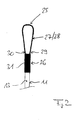
- shows an end portion of the cable according to
figure 1 ; - figures 3a to 3g
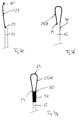
- illustrate a preferred method for manufacturing the cable;
- figure 4
- shows the end portion according to
figure 2 together with a ring; and - figure 5
- shows the end portion according to
figure 2 together with a hook. -
Figure 1 shows a schematic view of a preferred embodiment of a cable which is a preassembledoptical cable 10. The preassembledoptical cable 10 comprises ariser cable 11 and at least onetether cable 12 branched off from saidriser cable 10. According to the embodiment offigure 1 , the preassembledoptical cable 10 comprises threetether cables 12. - The
riser cable 11 comprises acable jacket 13 surrounding a plurality of optical fiber bundles (not shown), wherein each of said optical fiber bundles comprises a buffer tube surrounding a plurality of individual optical fibers. - The
riser cable 11 further comprises a furcation adapter 14 mounted to a first end 15 of saidriser cable 11, said furcation adapter 15 splitting out the individual optical fibers 16 of saidriser cable 11 in a way that each of said individual optical fibers 16 of saidriser cable 11 is surrounded by an individual protection tube 17 and that each of said individual optical fibers 16 of saidriser cable 11 can be connected to an optical fiber of a distribution cable. - The individual optical fibers 16 of said
riser cable 11 are preferably connectorized with fiberoptic connectors 18 in order to connect each of said individual optical fibers 16 of saidriser cable 11 to an optical fiber of said distribution cable at a main distribution point. - The
riser cable 11 further comprises midspan access locations 19, wherein in the region of at least one of these midspan access locations 19 at least onetether cable 12 is branched off from saidriser cable 11. - According to the embodiment of
figure 1 , the preassembledoptical cable 10 comprises three midspan access locations 19, whereby at each midspan access location 19 onetether cable 12 is branched off from saidriser cable 11. - Each of said
tether cables 12 of the preassembledoptical cable 10 comprises one unspliced optical fiber bundle of saidriser cable 11 surrounded by anprotection tube 20. - A
furcation adapter 21 is mounted to eachtether cable 12, saidfurcation adapter 21 splitting out the individualoptical fibers 22 of eachtether cable 12 in a way that each of said individualoptical fibers 22 of eachtether cable 12 is surrounded by an individual protection 23 tube and that each of said individualoptical fibers 22 of eachtether cable 12 can be connected to an optical fiber of a drop cable. - The individual
optical fibers 22 of eachtether cable 12 are preferably connectorized with fiberoptic connectors 24 in order to connect each of said individual optical fibers of eachtether cable 12 to an optical fibers of a drop cable an thereby to subscribers or end users. - The
riser cable 11 further comprises a pullingmember 25 for pulling theriser cable 11 together with thetether cables 12 through a cable duct during installation. The pullingmember 25 is assigned to asecond end 26 of saidriser cable 11. The pulling member 15 is an integral element of the cable, namely in the shown embodiment of theriser cable 11. - It is possible that an additional mid
span access location 19 for branching off anadditional tether cable 12 from saidriser cable 11 is located in the region of thesecond end 26 of saidriser cable 11. - The
riser cable 11 further comprises a plurality ofstrength members 27 releasing the optical fibers of saidriser cable 11 from mechanical stress during installation and/or operation of theriser cable 11. - The pulling
member 25 is made from thestrength members 27 of theriser cable 11 in a way that a loop 28 made from thestrength members 27 of theriser cable 11 provides thepulling member 25. - In order to form the loop 28 from the
strength members 27 of theriser cable 11 thecable jacket 13 and preferably the optical fibers of saidriser cable 11 are cut atsecond end 26 of theriser cable 11. - After cutting the
cable jacket 13 and preferably the optical fibers of saidriser cable 11 the cutsection cable jacket 13 and preferably the cut sections of the optical fibers are removed from theriser cable 11 thereby providingstrength members 27 protruding from thecable jacket 13 and preferably protruding from the optical fibers of saidriser cable 11. The free length of saidstrength members 27 protruding from the cable jacket 17 is formed to the loop 28 in order to provide the pullingmember 25. - Alternatively or in addition, one or more of said
strength members 27 can be connected to a piece of hardware (metal or plastic) that has a loop or eye formed in the hardware and then covered by the heat shrink or molded plastic materials. - The free length of said
strength members 27 protruding from thecable jacket 13 is formed to the loop 28 in a way that afirst end 29 of the loop 28 is formed by a middle section of thestrength members 27, that asecond end 30 of the loop 28 is formed by an end section of thestrength members 27, and that thesecond end 30 of the loop 28 is attached to thecable jacket 13 by example given a glue. - Both ends 29, 30 of the loop 28 providing the pulling
member 25 and a portion of thecable jacket 13 to which thesecond end 30 of the loop 28 or thesecond end 30 of thestrength members 27 is attached are surrounded by aheat shrink element 31. - Said heat shrink
element 31 secures precisely both ends 30 of the loop 28 orstrength members 27 at theriser cable 11 to provide strong hold and smooth shape. Alternatively, a moulded plastic as for example by injection moulding or extrusion can cover one or more of thestrength members 27. - In order to form the loop 28 of the
strength members 27 for providing the pullingmember 25, thestrength members 27 protruding thecable jacket 13 are split up into at least threegroups 32, 33 and 34 ofstrength members 27, whereby saidgroups 32, 33 and 34 ofstrength members 27 are according tofigures 3a to 3d interweaved thereby formingtwisted strength members 27 according tofigure 3e . - After the
strength members 27 are interweaved thesecond end 30 of thetwisted strength members 27 is according tofigure 3f attached to thecable jacket 13 of theriser cable 11 forming the loop 28. - Finally the heat shrink
element 31 or moulded plastic is according tofigure 3g used to secure thetwisted strength members 27 at theriser cable 11 thereby providing the twisted pullingmember 25. - In order to form the loop 28 from the
strength members 27 of theriser cable 11 it is also possible to cut thecable jacket 13, the optical fibers of saidriser cable 11 and thestrength members 27 at theend 26 of theriser cable 11, wherein the cut ends of thecable jacket 13 and of the optical fibers are removed, and wherein the cut ends of saidstrength members 27 form the loop 28 in a way that thefirst end 29 of the loop 28 and thesecond end 30 of the loop 28 are both formed by end sections of thecut strength members 27, and that thefirst end 29 and thesecond end 30 of the loop 28 are both attached to thecable jacket 13 of theriser cable 11. - The
strength members 27 are preferably made from Kevlar strands. However, the pullingmember 25 can be used in connection with cables having any type of strength members. - The pulling
member 25 relates mainly to indoor fiber optic cables like the preassembled optical cable according to the embodiment offigure 1 . However, the pullingmember 25 can be used also in other types of cables like copper cables, fiber optic cables or hybrid cables for indoor and outdoor applications. - The pulling member allows an easy installation of the cable and provides a flexible, robust pulling member. All cable dimensions including the dimension of pulling member are kept as small as possible.
- The pulling member allows making a pulling member on one end of the cable using strength members of the cable.
- The pulling member allows easy pulling of cables through very small ducts. It can hold pulling force over 500N.
- The pulling member is flexible, small and easy to attach to installation equipment. The pulling member can be easily attached to any installation equipment. The pulling member can be used for an installation by hand not using additional installation equipment.
- The pulling member uses existing strength members of the cable, therefore it's very strong and it's not necessary to use any other parts. However if needed, any other parts as rings 35 (see
figure 4 ), hooks 36 (seefigure 5 ), etc. any type of material can be easily attached. -
- 10
- preassembled optical cable
- 11
- riser cable
- 12
- tether cable
- 13
- cable jacket
- 14
- furcation adapter
- 15
- first end
- 16
- individual optical fiber
- 17
- individual protection tube
- 18
- fiber optic connector
- 19
- mid span access location
- 20
- protection tube
- 21
- furcation adapter
- 22
- individual optical fiber
- 23
- individual protection tube
- 24
- fiber optic connector
- 25
- pulling member
- 26
- second end
- 27
- strength members
- 28
- loop
- 29
- first end
- 30
- second end
- 31
- heat shrink or moulded plastic element
- 32
- group of strength members
- 33
- group of strength members
- 34
- group of strength members
- 35
- ring
- 36
- hook
Claims (13)
- Cable, especially optical cable, comprising
a cable jacket (13) surrounding a plurality of data transmission elements, especially a plurality of optical fibers;
strength members (27) releasing the data transmission elements from mechanical stress during installation and/or operation of the cable;
a pulling member (25) for pulling the cable through a cable duct during installation of the cable;
characterised in that
said pulling member (25) is an integral element of the cable. - The cable as claimed in claim 1, characterised in that said pulling member (27) is made from the strength members (27) of the cable.
- The cable as claimed in claim 1 or 2, characterised in that a loop (28) made from the strength members (27) of the cable provides the pulling member (25).
- The cable as claimed in claim 3, characterised in that the cable jacket (13) and preferably the data transmission elements are cut at an end (26) of the cable and removed from the cable thereby providing strength members (27) protruding the cable jacket (13) and preferably protruding the data transmission elements, wherein the free length of said strength members (27) protruding the cable jacket (13) provides the loop (28) in a way that a first end (29) of the loop (28) is formed by a middle section of the strength members (27), that a second end (30) of the loop (28) is formed by an end section of the strength members (27), and that the second end (30) of the loop (28) is attached to the cable jacket (13).
- The cable as claimed in claim 3, characterised in that the cable jacket, the data transmission elements and the strength members are all cut at an end of the cable, wherein the cut ends of the cable jacket and of the data transmission elements are removed, and wherein the cut ends of said strength members provide the loop in a way that a first end of the loop and a second end of the loop are both formed by end sections of the cut strength members, and that the first end and the second end of the loop are both attached to the cable jacket.
- The cable as claimed in claim 4 or 5, characterised in that both ends of the loop (28) providing the pulling member and a portion of the cable jacket (13) to which the or each end section of the strength members (27) is attached are surrounded by a heat shrink or moulded plastic element (31).
- The cable as claimed in one of claims 2 to 6, characterised in that the strength members (27) providing the pulling member (25) are split up into at least three groups, whereby said groups of strength members are interweaved thereby forming a twisted pulling member (25).
- The cable as claimed in one of claims 1 to 7, characterised in that said cable is a optical cable comprising a riser cable (11) and at least one tether cable (12) branched off from said riser cable, wherein:said riser cable (11) comprises a cable jacket (13) surrounding a plurality of optical fiber bundles, wherein each of said optical fiber bundles comprises a buffer tube surrounding a plurality of individual optical fibers;said riser cable (11) further comprises mid span access locations (19), wherein in the region of at least one of these mid span access locations (19) at least one tether cable (20) is branched off from said riser cable (11); andsaid pulling member (25) is an integral element of the said riser cable (11).
- The cable as claimed in claim 8, characterised in that said pulling member (25) is formed at one end (26) of the said riser cable (11).
- A method for manufacturing a cable as claimed in one of claims 1 to 9, the method comprising the steps of:providing a cable comprising a cable jacket surrounding a plurality of data transmission elements and further comprising strength members releasing the data transmission elements from mechanical stress during installation and/or operation of the cable;removing the cable jacket at an end of said cable; andforming a pulling member from the strength members of the cable thereby providing a pulling member being an integral element of the cable.
- The method as claimed in claim 10, wherein the step of removing the cable jacket comprises the step of cutting the cable jacket and the step of cutting the data transmission elements but not cutting the strength members, the step of removing the cut section of cable jacket and the cut sections of data transmission elements from the said cable and thereby providing strength members protruding from the cable jacket and the data transmission elements.
- The method as claimed in claim 10 or 11, wherein the step of forming the pulling member comprises the step of forming a loop from the strength members protruding from the cable jacket and the data transmission elements and securing the loop at a portion of the cable jacket.
- The method as claimed in claim 12, wherein the step of forming the loop comprises the step of splitting up the strength members protruding the cable jacket into at least three groups, and the step of interweaving said groups of strength members thereby forming a twisted loop which provides the pulling member.
Priority Applications (1)
| Application Number | Priority Date | Filing Date | Title |
|---|---|---|---|
| EP09001665A EP2216666A1 (en) | 2009-02-06 | 2009-02-06 | Cable and method for manufacturing the same |
Applications Claiming Priority (1)
| Application Number | Priority Date | Filing Date | Title |
|---|---|---|---|
| EP09001665A EP2216666A1 (en) | 2009-02-06 | 2009-02-06 | Cable and method for manufacturing the same |
Publications (1)
| Publication Number | Publication Date |
|---|---|
| EP2216666A1 true EP2216666A1 (en) | 2010-08-11 |
Family
ID=40668210
Family Applications (1)
| Application Number | Title | Priority Date | Filing Date |
|---|---|---|---|
| EP09001665A Withdrawn EP2216666A1 (en) | 2009-02-06 | 2009-02-06 | Cable and method for manufacturing the same |
Country Status (1)
| Country | Link |
|---|---|
| EP (1) | EP2216666A1 (en) |
Cited By (2)
| Publication number | Priority date | Publication date | Assignee | Title |
|---|---|---|---|---|
| WO2013082204A1 (en) * | 2011-11-30 | 2013-06-06 | Corning Cable Systems Llc | Cable pulling grip having toolless removal |
| WO2021154572A1 (en) | 2020-01-29 | 2021-08-05 | Corning Research & Development Corporation | Preconnectorized distribution cable assemblies and methods of making using a pull string |
Citations (8)
| Publication number | Priority date | Publication date | Assignee | Title |
|---|---|---|---|---|
| US3805667A (en) * | 1970-08-21 | 1974-04-23 | Columbian Rope Co | Braided rope |
| US4170921A (en) * | 1978-03-17 | 1979-10-16 | New England Ropes, Inc. | Braided rope |
| US4264129A (en) * | 1978-11-17 | 1981-04-28 | Spectronics, Inc. | Fiber bundle termination |
| DE3414363A1 (en) * | 1984-01-13 | 1985-10-17 | Roland 7000 Stuttgart Wolf | Tension-resistant and moisture-proof capping of optical waveguide cables, coaxial cables or power cables |
| JPH04328507A (en) * | 1991-03-25 | 1992-11-17 | Smiths Ind Plc | Optical fiber cable assembly |
| WO2000054081A1 (en) * | 1999-03-09 | 2000-09-14 | Litton Systems, Inc. | Sensor array cable and fabrication method |
| JP2001116968A (en) * | 1999-08-11 | 2001-04-27 | Toyokuni Electric Cable Co Ltd | Optical communication trunk cable and branching tool for optical communication trunk cable |
| US7277614B2 (en) | 2004-12-03 | 2007-10-02 | Corning Cable Systems Llc | Tether assembly having individual connector ports |
-
2009
- 2009-02-06 EP EP09001665A patent/EP2216666A1/en not_active Withdrawn
Patent Citations (8)
| Publication number | Priority date | Publication date | Assignee | Title |
|---|---|---|---|---|
| US3805667A (en) * | 1970-08-21 | 1974-04-23 | Columbian Rope Co | Braided rope |
| US4170921A (en) * | 1978-03-17 | 1979-10-16 | New England Ropes, Inc. | Braided rope |
| US4264129A (en) * | 1978-11-17 | 1981-04-28 | Spectronics, Inc. | Fiber bundle termination |
| DE3414363A1 (en) * | 1984-01-13 | 1985-10-17 | Roland 7000 Stuttgart Wolf | Tension-resistant and moisture-proof capping of optical waveguide cables, coaxial cables or power cables |
| JPH04328507A (en) * | 1991-03-25 | 1992-11-17 | Smiths Ind Plc | Optical fiber cable assembly |
| WO2000054081A1 (en) * | 1999-03-09 | 2000-09-14 | Litton Systems, Inc. | Sensor array cable and fabrication method |
| JP2001116968A (en) * | 1999-08-11 | 2001-04-27 | Toyokuni Electric Cable Co Ltd | Optical communication trunk cable and branching tool for optical communication trunk cable |
| US7277614B2 (en) | 2004-12-03 | 2007-10-02 | Corning Cable Systems Llc | Tether assembly having individual connector ports |
Non-Patent Citations (2)
| Title |
|---|
| PAUL ROSENBERG: "Don't Get Pulled in the Wrong Direction", ELECTRICAL CONSTRUCTION AND MAINTENANCE, ONLINE, 1 July 2000 (2000-07-01), XP002530045 * |
| THE FIBER OPTIC ASSOCIATION, INC.: "Installing Swivel Pulling Eyes on Fiber Optic Cable", 2008, XP002530046, Retrieved from the Internet <URL:www.thefoa.org/tech/ref/install/pullingeye.html> [retrieved on 20090529] * |
Cited By (7)
| Publication number | Priority date | Publication date | Assignee | Title |
|---|---|---|---|---|
| WO2013082204A1 (en) * | 2011-11-30 | 2013-06-06 | Corning Cable Systems Llc | Cable pulling grip having toolless removal |
| CN104246570A (en) * | 2011-11-30 | 2014-12-24 | 康宁光通信有限公司 | Cable pulling grip having toolless removal |
| US9110268B2 (en) | 2011-11-30 | 2015-08-18 | Corning Cable Systems Llc | Cable pulling grip having toolless removal |
| AU2012345969B2 (en) * | 2011-11-30 | 2016-03-03 | Corning Optical Communications LLC | Cable pulling grip having toolless removal |
| WO2021154572A1 (en) | 2020-01-29 | 2021-08-05 | Corning Research & Development Corporation | Preconnectorized distribution cable assemblies and methods of making using a pull string |
| EP4097523A4 (en) * | 2020-01-29 | 2024-06-12 | Corning Research & Development Corporation | PRE-CONNECTED DISTRIBUTION CABLE ASSEMBLY AND METHODS OF MANUFACTURING THE SAME USING A PULL CORD |
| US12298585B2 (en) | 2020-01-29 | 2025-05-13 | Corning Research & Development Corporation | Preconnectorized distribution cable assemblies and methods of making using a pull string |
Similar Documents
| Publication | Publication Date | Title |
|---|---|---|
| EP2216667B1 (en) | Fiber optic distribution device and fiber optic network including the same | |
| EP2527895B1 (en) | Fiber optic distribution device | |
| CN104508930B (en) | Fiber Optic Housing and Related Assemblies and Methods Using Clamping Assemblies for Cable Strain Relief | |
| US6215930B1 (en) | Remote-splitter fiber optic cable | |
| US7668432B2 (en) | Multi-drop closure systems and methods for fiber optic cabling | |
| WO2007091879A1 (en) | Optical fiber cable suited for blown installation or pushing installation in microducts of small diameter | |
| EP2705396B1 (en) | Optical fiber cable bundle | |
| CA2215639A1 (en) | Optical cable for data transmission on local area networks | |
| EP2216665A1 (en) | Fiber optic distribution device and fiber optic network including the same | |
| US10067310B2 (en) | Fiber optic drop cable assembly | |
| EP1982222B1 (en) | Optical fiber cable suited for blown installation or pushing installation in microducts of small diameter | |
| CN113284665A (en) | Photoelectric composite cable and photoelectric system | |
| EP2255235B1 (en) | Method of attachment of a connector to a fiber optic cable | |
| US9664864B2 (en) | Method for terminating high fiber count cables | |
| CN106537207B (en) | Method for installing multiple communication connections in a distribution network | |
| EP2157461A1 (en) | Preassembled optical cable and method for manufacturing preassemled optical cables | |
| US9329354B2 (en) | Branch distribution cable connectorization system | |
| US20120189256A1 (en) | Fiber Optic Cable Systems and Methods for Forming the Same | |
| CN105301717A (en) | Optical cable branching protection structure | |
| WO2018139999A1 (en) | Reduced diameter ruggedized fiber optic distribution cables | |
| EP3584619B1 (en) | Optical cable and wall-drilling auxiliary tool combined structure | |
| WO2004074900A1 (en) | Blowing of optical fiber cables into ducts | |
| US9715073B1 (en) | Optical trunk cable having web-connected sub-unitized configuration | |
| JP3875678B2 (en) | Optical fiber branch and distribution method, optical fiber sheet used in optical fiber branch and distribution method, and storage tray | |
| US20250132071A1 (en) | Communication cables with electrical and optical lanes |
Legal Events
| Date | Code | Title | Description |
|---|---|---|---|
| PUAI | Public reference made under article 153(3) epc to a published international application that has entered the european phase |
Free format text: ORIGINAL CODE: 0009012 |
|
| AK | Designated contracting states |
Kind code of ref document: A1 Designated state(s): AT BE BG CH CY CZ DE DK EE ES FI FR GB GR HR HU IE IS IT LI LT LU LV MC MK MT NL NO PL PT RO SE SI SK TR |
|
| AX | Request for extension of the european patent |
Extension state: AL BA RS |
|
| 17P | Request for examination filed |
Effective date: 20110208 |
|
| 17Q | First examination report despatched |
Effective date: 20110301 |
|
| AKX | Designation fees paid |
Designated state(s): AT BE BG CH CY CZ DE DK EE ES FI FR GB GR HR HU IE IS IT LI LT LU LV MC MK MT NL NO PL PT RO SE SI SK TR |
|
| STAA | Information on the status of an ep patent application or granted ep patent |
Free format text: STATUS: THE APPLICATION IS DEEMED TO BE WITHDRAWN |
|
| 18D | Application deemed to be withdrawn |
Effective date: 20140401 |