EP2216623A1 - Laser line-marking device - Google Patents
Laser line-marking device Download PDFInfo
- Publication number
- EP2216623A1 EP2216623A1 EP07816633A EP07816633A EP2216623A1 EP 2216623 A1 EP2216623 A1 EP 2216623A1 EP 07816633 A EP07816633 A EP 07816633A EP 07816633 A EP07816633 A EP 07816633A EP 2216623 A1 EP2216623 A1 EP 2216623A1
- Authority
- EP
- European Patent Office
- Prior art keywords
- slider
- linkage
- plate
- guiding
- recess
- Prior art date
- Legal status (The legal status is an assumption and is not a legal conclusion. Google has not performed a legal analysis and makes no representation as to the accuracy of the status listed.)
- Withdrawn
Links
Images


Classifications
-
- G—PHYSICS
- G01—MEASURING; TESTING
- G01C—MEASURING DISTANCES, LEVELS OR BEARINGS; SURVEYING; NAVIGATION; GYROSCOPIC INSTRUMENTS; PHOTOGRAMMETRY OR VIDEOGRAMMETRY
- G01C15/00—Surveying instruments or accessories not provided for in groups G01C1/00 - G01C13/00
- G01C15/002—Active optical surveying means
- G01C15/004—Reference lines, planes or sectors
Definitions
- the invention relates to a laser levelling device, in particular, to a laser levelling device comprising a central locking assembly for fixing the rod conveniently.
- a laser levelling device is widely used for projecting a visible marking consisting of a horizontal and/or a vertical line (or spot) on walls, floors or ceilings accurately by laser in the indoor decoration.
- the automatic laser levelling device can keep the accuracy of the projected horizontal and vertical line and 90 degree angle between them within a given inclination range.
- the laser levelling device generally has a pendulum and under the gravitational action of the pendulum, the laser lines projected by the lasers mounted on the pendulum can maintain the horizontal and/or vertical position, which further insures the accuracy of the construction.
- the operating environment usually is very severe, and it is hard to avoid vibration.
- the pendulum must be fixed in order to avoid the damage of the device caused by the vibration of the pendulum.
- the automatic laser levelling device with its pendulum in locked state can be placed in a tilted position by another auxiliary device for slope aligning.
- the conventional laser levelling device may include a clamping device, which may use a clamping plate and move the pendulum to one side of the device and clamp the pendulum on an inner wall.
- An object of the invention is to overcome the above problems.
- the object is achieved by providing a laser levelling device comprising a central locking assembly for fixing the rod easily.
- a laser levelling device of the invention may comprise a main body, a rod suspended from the main body, and a central locking assembly disposed on the lower portion of the main body;
- the central locking assembly comprises a linkage plate, a slider, a guiding plate, and two clamping plates, the linkage plate and the guiding plate are provided with a central hole respectively, the rod may pass through the central holes, the linkage plate may be fastened to the main body, the linkage plate is provided with two linkage slots along its radial direction, and two linkage cylinders may protrude downwardly from the linkage plate,
- the slider is provided with slider slots for receiving the linkage cylinders, from a side surface of the slider may protrude a slider cylinder, on the side of the slider which is adjacent to the central hole is formed a slider recess, above the linkage plate is the guiding plate, from which a guiding cylinder is protruding and is received in the above slider recess, the guiding plate is provided with two guiding slots
- the main body may further comprise a housing; the housing is provided with a rotary handle, the rotary handle is provided with a driving lever, and the driving lever is provided with a lever recess for receiving the said slider cylinder; a positioning plate is provided between the rotary handle and the driving lever; a positioning bulge is provided on the top part of the positioning plate.
- the laser levelling device can clamp the rod in position accurately and easily such that the laser levelling device is protected from damage.
- the laser levelling device 100 may comprise a main body 1 and a housing 2 for housing the main body 1.
- a rod 4 is suspended from the lower portion of the main body 1 and is provided with a laser 3. Said laser 3 is used to project a laser line or spot.
- a pendulum 41 is disposed on the free end of the rod 4.
- the housing 2 is provided with a rotary handle 5, and the rotary handle 5 is provided with a driving lever 51, a lever recess 511 is formed on the free end of the driving lever 51.
- a central locking assembly 6 is disposed on the lower portion of the main body 1. At the center of the central locking assembly 6 is a central hole 61 for being passed through by the rod 4.
- the central locking assembly 6 may comprise a linkage plate 62, a guiding plate 63 above the linkage plate 62, two clamping plates 64 above the guiding plate 63, and a slider 65 below the linkage plate 62.
- a slider cylinder 651 may protrude from a side surface of the slider 65 and is received in the lever recess 511.
- the linkage plate 62 is fastened to the main body 1 by screws (not shown), and is provided with two unconnected linkage slots 621 along its radial direction and arranged in a line.
- Two linkage cylinders 622 may protrude downwardly from the linkage plate 62, the slider 65 is provided with slider slots 652 for receiving the linkage cylinder 622.
- On the side of the slider 65 which is adjacent to the central holes 61 is formed a slider recess 653.
- the line connecting the two points for fixing the linkage cylinder 622 is not parallel to the linkage slots 621.
- the guiding plate 63 is provided above the linkage plate 62.
- a guiding cylinder 631 may protrude downwardly from the guiding plate 63 and is received in the slider recess 653.
- the guiding plate 63 is provided with two guiding slots 633 arranged in parallel and tangent to the central hole 61.
- On the outer circumference of the guiding plate 63 may form a stop recess 632, which may cooperate with the main body 1 to prevent the guiding plate 63 from rotating excessively.
- Each of the two clamping plates 64 is provided with a curved recess 641 which is adjacent to the central hole 61 and a clamping cylinder 642, which is received in the guiding slots 633.
- a positioning plate 52 is provided between the rotary handle 5 and the driving lever 51, and a positioning bulge 521 is provided on the top part of the positioning plate 52.
- the positioning bulge 521 can be fixed relative to the inner wall of the housing 2 (see Fig. 1 ) to increase the friction between the rotary handle 5 and the housing 2 and to prevent the rotary handle 5 from rotating accidentally.
- the rod 4 may pass through the central holes 61 and is in a vertical position under the gravitational action of the pendulum 41.
- the guiding cylinder 631 is located at one end of the linkage recess 623, and each linkage cylinder 622 is located at one end of the slider slots 652.
- the clamping cylinder 642 is located at the outer end of the guiding slots 633, and is located at the outer end of the linkage slots 621 via the guiding slots 633.
- the whole guiding plate 63 may rotate to make the clamper cylinder 642 move inwardly along the guiding slots 633. Because the clamping cylinders 642 are fastened to the clamping plates 64, the clamping plates 64 can move inwardly, locking the rod in position. Moreover, under the guidance of the two curved recess 641, the rod 4 can be centered at the center of the central hole 61. The locking assembly 6 may return to the released state simply by reversing the above process.
- the object of the invention is achieved by using the laser levelling device of the invention.
- the laser levelling device of the invention with its locking assembly 6 in the locked state is placed in a horizontal position, it can ensure that the rod 4 keeps the vertical position automatically under the action of gravity.
- the laser line or spots projected by the laser 3 can still be kept in the horizontal or vertical position.
- the locking assembly in the locked state the laser line or spot can maintain their original position.
- the cross consisting of the horizontal and the vertical line projected by the laser levelling device can be used to obtain a steady slope line with a given inclined angle.
- the laser levelling device with its rod locked is protected from damage caused by the impact generated by the over-rocking of the pendulum. More particularly, in the prior art, with the pendulum locked for long term and 4 mini bearings supporting the pendulum be subjected to lateral forces, the device can be damaged or its operation accuracy may be greatly lowered and hence the device may fail. In contrast, the laser levelling device of the invention can avoid all of this.
- the locking assembly 6 according to the invention is easy to use, and the locked rod can be centered under the guidance of the curved recess.
Landscapes
- Physics & Mathematics (AREA)
- Engineering & Computer Science (AREA)
- General Physics & Mathematics (AREA)
- Radar, Positioning & Navigation (AREA)
- Remote Sensing (AREA)
- Conveying And Assembling Of Building Elements In Situ (AREA)
Abstract
Description
- The invention relates to a laser levelling device, in particular, to a laser levelling device comprising a central locking assembly for fixing the rod conveniently.
- A laser levelling device is widely used for projecting a visible marking consisting of a horizontal and/or a vertical line (or spot) on walls, floors or ceilings accurately by laser in the indoor decoration. The automatic laser levelling device can keep the accuracy of the projected horizontal and vertical line and 90 degree angle between them within a given inclination range. The laser levelling device generally has a pendulum and under the gravitational action of the pendulum, the laser lines projected by the lasers mounted on the pendulum can maintain the horizontal and/or vertical position, which further insures the accuracy of the construction. However, in the construction site, the operating environment usually is very severe, and it is hard to avoid vibration. In addition, during the transport, the pendulum must be fixed in order to avoid the damage of the device caused by the vibration of the pendulum. Furthermore, in another use, the automatic laser levelling device with its pendulum in locked state can be placed in a tilted position by another auxiliary device for slope aligning.
- To solve the above problems, the conventional laser levelling device may include a clamping device, which may use a clamping plate and move the pendulum to one side of the device and clamp the pendulum on an inner wall.
- However, such a clamping device can cause some problems. Firstly, because the pendulum is clamped on the inner side wall, the bearing suspending the pendulum may be subject to a lateral force, resulting in the damage of the bearing and lower operation accuracy. Secondly, the use of the laser levelling device with its pendulum clamped on the inner side wall is limited. In order to insure high operational accuracy of the laser levelling device, the pendulum must be in its free state, and in order for the pendulum to maintain such a state, the forces on the bearing must be uniform. But, the above clamping device could not fulfill the above functions, additionally it is not easy to use.
- An object of the invention is to overcome the above problems. The object is achieved by providing a laser levelling device comprising a central locking assembly for fixing the rod easily.
- In one aspect of the invention, a laser levelling device of the invention may comprise a main body, a rod suspended from the main body, and a central locking assembly disposed on the lower portion of the main body; the central locking assembly comprises a linkage plate, a slider, a guiding plate, and two clamping plates, the linkage plate and the guiding plate are provided with a central hole respectively, the rod may pass through the central holes, the linkage plate may be fastened to the main body, the linkage plate is provided with two linkage slots along its radial direction, and two linkage cylinders may protrude downwardly from the linkage plate, the slider is provided with slider slots for receiving the linkage cylinders, from a side surface of the slider may protrude a slider cylinder, on the side of the slider which is adjacent to the central hole is formed a slider recess, above the linkage plate is the guiding plate, from which a guiding cylinder is protruding and is received in the above slider recess, the guiding plate is provided with two guiding slots which are arranged in parallel and tangent to the central hole respectively, each clamping plate comprising a curved recess which is adjacent to the central hole and a clamping cylinder which is received in the guiding slot.
- In another aspect of the invention, on the inner circumference of the linkage plate, in a position where the slider recess is disposed, is formed a linkage recess for receiving the said guiding cylinder; the line on the linkage plate connecting the points for fixing two linkage cylinders is not parallel to the linkage slots; the main body may further comprise a housing; the housing is provided with a rotary handle, the rotary handle is provided with a driving lever, and the driving lever is provided with a lever recess for receiving the said slider cylinder; a positioning plate is provided between the rotary handle and the driving lever; a positioning bulge is provided on the top part of the positioning plate.
- According to the invention, the laser levelling device can clamp the rod in position accurately and easily such that the laser levelling device is protected from damage.
- The invention will be described in detail by means of embodiments and with reference to the drawings, in which:
-
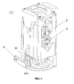
Fig. 1 is a perspective view of the laser levelling device of the invention; -
Fig. 2 is a perspective view of the laser levelling device of the invention, with the housing removed. -
Fig. 3 is an exploded view of the rod and the central locking assembly of the laser levelling device of the invention; -
Fig. 4 is a perspective view of the rod and the central locking assembly of the laser levelling device of the invention in a released state -
Fig. 5 is a perspective view of the rod and the central locking assembly of the laser levelling device of the invention in a locked state. - As shown in
Fig. 1 andFig. 2 , thelaser levelling device 100 may comprise amain body 1 and ahousing 2 for housing themain body 1. Arod 4 is suspended from the lower portion of themain body 1 and is provided with alaser 3. Saidlaser 3 is used to project a laser line or spot. Apendulum 41 is disposed on the free end of therod 4. Thehousing 2 is provided with arotary handle 5, and therotary handle 5 is provided with adriving lever 51, alever recess 511 is formed on the free end of thedriving lever 51. Acentral locking assembly 6 is disposed on the lower portion of themain body 1. At the center of thecentral locking assembly 6 is acentral hole 61 for being passed through by therod 4. Thecentral locking assembly 6 may comprise alinkage plate 62, a guidingplate 63 above thelinkage plate 62, twoclamping plates 64 above the guidingplate 63, and aslider 65 below thelinkage plate 62. Aslider cylinder 651 may protrude from a side surface of theslider 65 and is received in thelever recess 511. - As shown in
Fig. 2 andFig. 3 , thelinkage plate 62 is fastened to themain body 1 by screws (not shown), and is provided with twounconnected linkage slots 621 along its radial direction and arranged in a line. Twolinkage cylinders 622 may protrude downwardly from thelinkage plate 62, theslider 65 is provided withslider slots 652 for receiving thelinkage cylinder 622. On the side of theslider 65 which is adjacent to thecentral holes 61 is formed aslider recess 653. The line connecting the two points for fixing thelinkage cylinder 622 is not parallel to thelinkage slots 621. On theslider 65, there are twoslider recesses 653 arranged in parallel. Thus, the turning torque generated by thewhole slider 65 can be increased. The guidingplate 63 is provided above thelinkage plate 62. A guidingcylinder 631 may protrude downwardly from the guidingplate 63 and is received in theslider recess 653. On the inner circumference of thelinkage plate 62, in a position where the slider recess is disposed, may form a linkage recess 623. The guidingplate 63 is provided with two guidingslots 633 arranged in parallel and tangent to thecentral hole 61. On the outer circumference of the guidingplate 63 may form astop recess 632, which may cooperate with themain body 1 to prevent the guidingplate 63 from rotating excessively. Each of the twoclamping plates 64 is provided with acurved recess 641 which is adjacent to thecentral hole 61 and aclamping cylinder 642, which is received in the guidingslots 633. - As shown in
Fig. 3-5 , apositioning plate 52 is provided between therotary handle 5 and thedriving lever 51, and apositioning bulge 521 is provided on the top part of thepositioning plate 52. Thepositioning bulge 521 can be fixed relative to the inner wall of the housing 2 (seeFig. 1 ) to increase the friction between therotary handle 5 and thehousing 2 and to prevent therotary handle 5 from rotating accidentally. - In operation, when the
central locking assembly 6 is in a released state, therod 4 may pass through thecentral holes 61 and is in a vertical position under the gravitational action of thependulum 41. At this time, the guidingcylinder 631 is located at one end of the linkage recess 623, and eachlinkage cylinder 622 is located at one end of theslider slots 652. Theclamping cylinder 642 is located at the outer end of theguiding slots 633, and is located at the outer end of thelinkage slots 621 via theguiding slots 633. When turning therotary handle 5, the lever recess 511 of thedriving lever 51 may drive theslider cylinder 651 into horizontal movement, and theslider 65 may cause the guidingcylinder 631 to move along a circular path. Thus, the whole guidingplate 63 may rotate to make theclamper cylinder 642 move inwardly along the guidingslots 633. Because theclamping cylinders 642 are fastened to theclamping plates 64, theclamping plates 64 can move inwardly, locking the rod in position. Moreover, under the guidance of the twocurved recess 641, therod 4 can be centered at the center of thecentral hole 61. Thelocking assembly 6 may return to the released state simply by reversing the above process. - In summary, the object of the invention is achieved by using the laser levelling device of the invention. When the laser levelling device of the invention with its
locking assembly 6 in the locked state is placed in a horizontal position, it can ensure that therod 4 keeps the vertical position automatically under the action of gravity. Thus, the laser line or spots projected by thelaser 3 can still be kept in the horizontal or vertical position. With the locking assembly in the locked state, the laser line or spot can maintain their original position. Moreover, when performing construction work, by using an external slope control device, the cross consisting of the horizontal and the vertical line projected by the laser levelling device can be used to obtain a steady slope line with a given inclined angle. In addition, during transport and storage, the laser levelling device with its rod locked is protected from damage caused by the impact generated by the over-rocking of the pendulum. More particularly, in the prior art, with the pendulum locked for long term and 4 mini bearings supporting the pendulum be subjected to lateral forces, the device can be damaged or its operation accuracy may be greatly lowered and hence the device may fail. In contrast, the laser levelling device of the invention can avoid all of this. In addition, the lockingassembly 6 according to the invention is easy to use, and the locked rod can be centered under the guidance of the curved recess.
Claims (7)
- A laser levelling device, comprising a main body, a rod suspended from the main body, and a central locking assembly disposed on the lower portion of the main body; the central locking assembly comprising a linkage plate, a slider, a guiding plate, and two clamping plates, the linkage plate and the guiding plate are provided with a central hole respectively, the rod may pass through the central holes, the linkage plate may be fastened to the main body, the linkage plate is provided with two linkage slots along its radial direction, and two linkage cylinders may protrude downwardly from the linkage plate, the slider is provided with slider slots for receiving the linkage cylinders, from a side surface of the slider may protrude a slider cylinder, on the side of the slider which is adjacent to the central hole is formed a slider recess, above the linkage plate is the guiding plate, from which a guiding cylinder is protruding and is received in the above slider recess, the guiding plate is provided with two guiding slots which are arranged in parallel and tangent to the central hole respectively, each clamping plate comprising a curved recess which is adjacent to the central hole and a clamping cylinder which is received in the guiding slot.
- A laser levelling device according to Claim 1, wherein, on the inner circumference of the linkage plate, in a position where the slider recess is disposed, is formed a linkage recess for receiving the said guiding cylinder,
- A laser levelling device according to Claim 1, wherein, the line on the linkage plate connecting the points for fixing two linkage cylinders is not parallel to the linkage slots.
- A laser levelling device according to Claim 1, wherein, the said main body may further comprise a housing.
- A laser levelling device according to Claim 4, wherein, the housing is provided with a rotary handle, the rotary handle is provided with a driving lever, and the driving lever is provided with a lever recess for receiving the said slider cylinder.
- A laser levelling device according to Claim 5, wherein, a positioning plate is provided between the rotary handle and the driving lever.
- A laser levelling device according to Claim 6, wherein, a positioning bulge is provided on the top part of the positioning plate.
Applications Claiming Priority (1)
| Application Number | Priority Date | Filing Date | Title |
|---|---|---|---|
| PCT/CN2007/003020 WO2009052647A1 (en) | 2007-10-22 | 2007-10-22 | Laser line-marking device |
Publications (2)
| Publication Number | Publication Date |
|---|---|
| EP2216623A1 true EP2216623A1 (en) | 2010-08-11 |
| EP2216623A4 EP2216623A4 (en) | 2011-03-23 |
Family
ID=40579021
Family Applications (1)
| Application Number | Title | Priority Date | Filing Date |
|---|---|---|---|
| EP07816633A Withdrawn EP2216623A4 (en) | 2007-10-22 | 2007-10-22 | DEVICE FOR MARKING LASER LINES |
Country Status (2)
| Country | Link |
|---|---|
| EP (1) | EP2216623A4 (en) |
| WO (1) | WO2009052647A1 (en) |
Cited By (4)
| Publication number | Priority date | Publication date | Assignee | Title |
|---|---|---|---|---|
| CN103278120A (en) * | 2013-06-18 | 2013-09-04 | 孟庆周 | Contact type measurement head structure |
| DE102014218185A1 (en) * | 2014-09-11 | 2016-03-17 | Robert Bosch Gmbh | Method for mounting a pendulum laser device |
| DE102014218210A1 (en) * | 2014-09-11 | 2016-03-17 | Robert Bosch Gmbh | Method for mounting a pendulum laser device |
| EP3418687A1 (en) * | 2017-06-20 | 2018-12-26 | Robert Bosch GmbH | Laser levelling apparatus with auto locking system and auto locking method |
Family Cites Families (8)
| Publication number | Priority date | Publication date | Assignee | Title |
|---|---|---|---|---|
| JP3487837B2 (en) * | 2001-06-13 | 2004-01-19 | 株式会社オーディオテクニカ | Laser marking device |
| JP4198018B2 (en) * | 2003-10-03 | 2008-12-17 | 三洋電機株式会社 | Laser line marker |
| CN2718518Y (en) * | 2004-06-18 | 2005-08-17 | 南京德朔实业有限公司 | Laser striping machine |
| JP2006119034A (en) * | 2004-10-22 | 2006-05-11 | Sanyo Electric Co Ltd | Laser line marker |
| CN2760511Y (en) * | 2004-12-24 | 2006-02-22 | 苏州一光镭射仪器有限公司 | Cross line laser |
| JP4712452B2 (en) * | 2005-06-20 | 2011-06-29 | 株式会社マイゾックス | Laser marking device |
| CN101078623B (en) * | 2006-05-26 | 2010-05-12 | 南京德朔实业有限公司 | Self-leveling laser marking device and control method thereof |
| DE102007007084B4 (en) * | 2007-02-13 | 2009-07-30 | Leica Geosystems Ag | Leveling, plummet and angle calibration instrument with pendulum suspended solder body |
-
2007
- 2007-10-22 WO PCT/CN2007/003020 patent/WO2009052647A1/en not_active Ceased
- 2007-10-22 EP EP07816633A patent/EP2216623A4/en not_active Withdrawn
Cited By (6)
| Publication number | Priority date | Publication date | Assignee | Title |
|---|---|---|---|---|
| CN103278120A (en) * | 2013-06-18 | 2013-09-04 | 孟庆周 | Contact type measurement head structure |
| CN103278120B (en) * | 2013-06-18 | 2015-09-23 | 孟庆周 | A kind of contact type measurement header structure |
| DE102014218185A1 (en) * | 2014-09-11 | 2016-03-17 | Robert Bosch Gmbh | Method for mounting a pendulum laser device |
| DE102014218210A1 (en) * | 2014-09-11 | 2016-03-17 | Robert Bosch Gmbh | Method for mounting a pendulum laser device |
| DE102014218185B4 (en) * | 2014-09-11 | 2019-06-19 | Robert Bosch Gmbh | Method for mounting a pendulum laser device |
| EP3418687A1 (en) * | 2017-06-20 | 2018-12-26 | Robert Bosch GmbH | Laser levelling apparatus with auto locking system and auto locking method |
Also Published As
| Publication number | Publication date |
|---|---|
| WO2009052647A1 (en) | 2009-04-30 |
| EP2216623A4 (en) | 2011-03-23 |
Similar Documents
| Publication | Publication Date | Title |
|---|---|---|
| US9010742B2 (en) | Part fixturing systems having expanding clamping devices | |
| EP2216623A1 (en) | Laser line-marking device | |
| US7070366B2 (en) | Drill stand for a core drilling machine | |
| EP3309510A1 (en) | Height-adjustable laser level apparatus | |
| US20200131788A1 (en) | Construction jig | |
| JP2014069348A (en) | Guide apparatus | |
| EP3434433A1 (en) | Cutting tool holding device | |
| JP2021126884A (en) | Scribe head and scribe device | |
| US7543391B2 (en) | Leveling, plumbing, and angular calibration instrument with a swinging suspended vertical body | |
| CN107378317A (en) | Sliding clamp position-limit mechanism | |
| JP3408794B2 (en) | Fixing table | |
| JP4617152B2 (en) | Cutting material positioning fence for cutting machine | |
| JPWO2005120750A1 (en) | Grooving device for elevator hoisting machine | |
| CN105881195B (en) | Double end flat grinding device | |
| KR101938405B1 (en) | Staff Equipment For Leveling | |
| JP4259991B2 (en) | Inking device | |
| JP2004338087A (en) | Machine Tools | |
| KR20180098941A (en) | Pendent arm | |
| US7556107B2 (en) | Construction machine for foundation construction | |
| JP2018500188A (en) | Nailing machine | |
| EP1726866A2 (en) | Support for film cameras | |
| JP4881204B2 (en) | Alignment device | |
| KR102572279B1 (en) | Electric drill for easy level check | |
| JP3234776U (en) | Cutting device | |
| JP2005227061A (en) | Receiver positioning attachment |
Legal Events
| Date | Code | Title | Description |
|---|---|---|---|
| PUAI | Public reference made under article 153(3) epc to a published international application that has entered the european phase |
Free format text: ORIGINAL CODE: 0009012 |
|
| 17P | Request for examination filed |
Effective date: 20100521 |
|
| AK | Designated contracting states |
Kind code of ref document: A1 Designated state(s): AT BE BG CH CY CZ DE DK EE ES FI FR GB GR HU IE IS IT LI LT LU LV MC MT NL PL PT RO SE SI SK TR |
|
| AX | Request for extension of the european patent |
Extension state: AL BA HR MK RS |
|
| DAX | Request for extension of the european patent (deleted) | ||
| A4 | Supplementary search report drawn up and despatched |
Effective date: 20110221 |
|
| RIC1 | Information provided on ipc code assigned before grant |
Ipc: G01C 15/00 20060101AFI20090519BHEP |
|
| STAA | Information on the status of an ep patent application or granted ep patent |
Free format text: STATUS: THE APPLICATION IS DEEMED TO BE WITHDRAWN |
|
| 18D | Application deemed to be withdrawn |
Effective date: 20110521 |