EP2216582B1 - System for mounting an object to a surface - Google Patents
System for mounting an object to a surface Download PDFInfo
- Publication number
- EP2216582B1 EP2216582B1 EP09157597A EP09157597A EP2216582B1 EP 2216582 B1 EP2216582 B1 EP 2216582B1 EP 09157597 A EP09157597 A EP 09157597A EP 09157597 A EP09157597 A EP 09157597A EP 2216582 B1 EP2216582 B1 EP 2216582B1
- Authority
- EP
- European Patent Office
- Prior art keywords
- mounting
- openings
- template
- wall
- flat screen
- Prior art date
- Legal status (The legal status is an assumption and is not a legal conclusion. Google has not performed a legal analysis and makes no representation as to the accuracy of the status listed.)
- Active
Links
- 125000006850 spacer group Chemical group 0.000 claims description 14
- 238000004806 packaging method and process Methods 0.000 claims description 4
- 238000000034 method Methods 0.000 description 8
- 238000005553 drilling Methods 0.000 description 2
- 230000014759 maintenance of location Effects 0.000 description 2
- 238000013507 mapping Methods 0.000 description 2
- 239000000463 material Substances 0.000 description 2
- 239000000123 paper Substances 0.000 description 2
- 238000010420 art technique Methods 0.000 description 1
- 230000001419 dependent effect Effects 0.000 description 1
- 230000003993 interaction Effects 0.000 description 1
- 230000002262 irrigation Effects 0.000 description 1
- 238000003973 irrigation Methods 0.000 description 1
- 239000003562 lightweight material Substances 0.000 description 1
- 238000005259 measurement Methods 0.000 description 1
- 239000002184 metal Substances 0.000 description 1
- 230000004048 modification Effects 0.000 description 1
- 238000012986 modification Methods 0.000 description 1
- 230000002093 peripheral effect Effects 0.000 description 1
Images


Classifications
-
- F—MECHANICAL ENGINEERING; LIGHTING; HEATING; WEAPONS; BLASTING
- F16—ENGINEERING ELEMENTS AND UNITS; GENERAL MEASURES FOR PRODUCING AND MAINTAINING EFFECTIVE FUNCTIONING OF MACHINES OR INSTALLATIONS; THERMAL INSULATION IN GENERAL
- F16M—FRAMES, CASINGS OR BEDS OF ENGINES, MACHINES OR APPARATUS, NOT SPECIFIC TO ENGINES, MACHINES OR APPARATUS PROVIDED FOR ELSEWHERE; STANDS; SUPPORTS
- F16M13/00—Other supports for positioning apparatus or articles; Means for steadying hand-held apparatus or articles
- F16M13/02—Other supports for positioning apparatus or articles; Means for steadying hand-held apparatus or articles for supporting on, or attaching to, an object, e.g. tree, gate, window-frame, cycle
-
- A—HUMAN NECESSITIES
- A47—FURNITURE; DOMESTIC ARTICLES OR APPLIANCES; COFFEE MILLS; SPICE MILLS; SUCTION CLEANERS IN GENERAL
- A47G—HOUSEHOLD OR TABLE EQUIPMENT
- A47G1/00—Mirrors; Picture frames or the like, e.g. provided with heating, lighting or ventilating means
- A47G1/16—Devices for hanging or supporting pictures, mirrors, or the like
- A47G1/20—Picture hooks; X-hooks
- A47G1/205—Devices for positioning picture hooks on a wall
Definitions
- the present invention relates to a system according to the preamble of claim 1.
- a system of the initially-mentioned type is known, e.g., from US 2007/0251112 A1 .
- Flat panel displays are increasingly popular for both home and business uses. Because of their thin profiles, flat panel displays are typically mounted on load-bearing surfaces, such as walls or ceilings. Although flat panel displays are becoming increasingly thin, they are also increasing in width and height, making them heavy and difficult to maneuver when mounting.
- a typical mounting procedure requires a complex set of tasks, including locating studs behind drywall, measuring the distance between the mounting holes on the rear of the flat panel display or mounting plate, mapping the location of the mounting holes onto the wall and drilling screws into the wall to fix the display or mounting plate to the wall, making sure that the screws are drilled into locations that will allow the display to be level. Incorrect measurements, stud location, mapping or drilling can result in the display being mounted at an incorrect angle or require the long and complicated process of mounting to be repeated, leaving unsightly holes in the drywall.
- US 4325531 A discloses an apparatus for removably securing a container to a carrier rack
- US 4154037 A discloses a Pole support assembly
- US 2008163524 A1 discloses a picture frame
- US 5107601 A discloses a mounting template formed from a flexible strip of paper material and having indicia printed or formed on a first face thereof, the indicia defining hole patterns each of which includes circles representing hole locations.
- US 2007/251112 A1 discloses a template for mounting a plurality of different of irrigation controller models
- US 2008/0083865 A1 discloses a hanger that enables an easy alignment at the time of hanging a display main body on a wall.
- the present invention provides a system according to claim 1.
- multiple sets of openings corresponding to multiple configurations of mounting locations on flat screen televisions are provided.
- Three sets of openings, for example, may be provided that correspond to the 100mm x 100mm, 100mm x 200mm and 200mm x 200mm VESA standards.
- One embodiment of the invention further comprises a level that is secured within the mounting template.
- the mounting template is constructed of cardboard and includes fold lines to facilitate packaging and storage of the mounting template.
- the mounting template may include horizontal and vertical fold lines oriented such that the mounting template can be folded so that the three sets of openings overlap, and so that the first links can be inserted into the overlapped openings to retain the folded structure.
- the method also includes the steps of fastening second links (object spacers) to the object in the desired mounting configuration, and mounting the object to the surface by connecting the second links on the objects to the first links on the wall.
- the method may further include the step of removing the template from the surface after the first links are fastened to the surface.
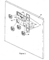
- FIG. 1 is a perspective view of a mounting template and wall brackets in a partially-folded configuration according to the invention.
- FIG. 2 is a perspective view showing the interaction between the wall of FIG. 1 and object spacers.
- FIG. 3 is a perspective view of the mounting template and wall brackets of FIG. 1 in a fully-extended configuration.
- FIG. 4 is a flowchart of a mounting system according to the present invention.
- FIGS. 1-3 A mounting system according to the present invention is illustrated in FIGS. 1-3 .
- the system includes a mounting template 100 that is fixed to a load-bearing surface 20, such as a wall or a ceiling, in order to facilitate the mounting of an object 40, such as a flat screen television, to the wall or ceiling.
- a load-bearing surface 20 such as a wall or a ceiling
- mounting template 100 is constructed of cardboard.
- template 100 may be constructed of other lightweight materials such as paper or plastic.
- Template 100 is fixed to surface 20 by a retaining pin, tape, putty or any other fastener capable of supporting the weight of mounting template 100 on surface 20.
- Mounting template 100 includes multiple openings that are sized to removably retain first links (wall brackets) 30, and that are spaced and configured to correspond to mounting locations on the object to be mounted.
- template 100 includes three sets of openings 112, 114 and 116. As shown in FIG. 3 , each set of openings corresponds to a different configuration of mounting locations on an object.
- the first set of openings 112 corresponds to a relatively small spacing of mounting locations
- the second set of openings 114 corresponds to a relatively large spacing of mounting locations
- the third set of openings 116 corresponds to a medium spacing of mounting locations.
- a level such as a bubble level 70, is removably attached to mounting template 100.
- Level 70 may be secured, for example, within an opening 118 formed in mounting template 100 or through any other suitable means capable of holding level 70 in place relative to mounting template 100.
- Level 70 ensures that mounting template 100 is level when fixed to surface 20.
- Template 100 in a fully-extended (completely unfolded) configuration is shown in FIG. 3 .
- the fully-extended template 100 is attached to surface 20 by appropriate fasteners such as retaining pins, for example.
- Wall brackets (first links) 30 are arranged within the appropriate set of openings 112, 114 or 116 to correspond to a configuration of mounting locations 42 on the object 40, such as a flat screen television, to be mounted on surface 20 ( FIG. 2 ).
- the sets of openings 112, 114 and 116 correspond to different standards of the Video Electronics Standards Association (VESA), in particular, to the 100mm x 100mm, 100mm x 200mm and 200mm x 200mm standards.
- the first set of openings 112 corresponds to the 100mm x 100mm VESA standard
- the second set of openings 114 correspond to the 200mm x 200mm VESA standard
- the third set of openings correspond to the 100mm x 200mm VESA standard.
- FIG. 1 shows wall brackets 30 being inserted into the first set of openings 112 for the 100mm x 100mm VESA standards
- FIG. 3 shows brackets 30 being inserted into the second set of openings 114 for the 200mm x 200mm VESA standard.
- VESA standards are of course merely examples of configurations to which openings 112, 114 and 116 may correspond, and the invention is not limited thereto.
- Sets of openings spaced in any other desired configuration may be provided, and more or less than three sets of openings may be provided.
- Template 100 may include just a single set of openings corresponding to a single mounting configuration, for example. However, providing multiple sets of openings provides greater flexibility in mounting objects with different mounting configurations.
- wall brackets 30 are inserted into the appropriate set of openings 112, 114 or 116, wall brackets 30 are fixed to surface 20 by an appropriate fastener such as, for example, a screw 50 and drywall anchor 52. Mounting template 100 may then be removed from surface 20.
- an appropriate fastener such as, for example, a screw 50 and drywall anchor 52.
- FIG. 2 shows wall brackets 30 attached to surface 20 through screws 50, after template 100 has been removed.
- Second links such as object spacers 60, are fixed to a plurality (four in the illustrated example) of mounting locations 42 arranged on object 40.
- Mounting locations 42 may be located on a rear surface of a flat screen television, for example.
- the spacing of mounting locations 42 on object 40 should correspond to the mounting configuration of wall brackets 30 on surface 20. For example, if object 40 is a flat screen television with a 200mm x 200mm VESA mounting configuration, then the second set of openings 114 should be chosen to mount wall brackets 30 to wall 20.
- Object spacers 60 can be constructed out of any material with sufficient strength to support the weight of object 40, such as, for example, plastic or metal. Object spacers 60 may be fixed to mounting locations 42 by any appropriate means such as a screw, for example. Once object spacers 60 are fixed to object 40, spacers 60 are inserted into wall brackets 30, as indicated by the arrows in Fig. 2 , to thereby mount object 40 on surface 20.
- first links are described as wall brackets 30 and the second links are described as object spacers 60, the scope of the invention is not limited thereto.
- First link 30 may be configured in any suitable fashion, as long as it is capable of holding the weight of object 40, securing to surface 20 and connecting to second link 60.
- the second link may be configured in any suitable fashion, as long as it is capable of holding the weight of object 40, and securing to mounting locations 42 of object 40 and connecting to first link 30.
- the second links may be integrated into or already connected in an appropriate configuration to the object to be mounted, rather than provided as mountable pieces.
- Mounting template 100 is also preferably configured to facilitate packaging, shipping and storage of template 100 and its associated components.
- template 100 includes horizontal folds 102 and vertical folds 104.
- the outer peripheral section of template 100 may be folded inward along vertical fold 104 such that the third set of openings 116 are aligned behind the first set of openings 112.
- the sections of template 100 including the second set of openings 114 may be folded inward (downward and upward) such that all of openings 112, 114 and 116 are stacked and aligned (see left side of FIG. 1 ).
- Wall brackets 30 can then be inserted into the overlapped openings 112, 114 and 116 to retain and provide a compact folded configuration for packaging.
- template 100 may also include a central slot 120 and side slots 122 for the purpose of storage and retention of spacers 60.
- side slots 122 overlap the ends of central slot 120 ( FIG. 2 ). Spacers 60 may then be placed side-by-side within slot 120 and the overlapping side slots 122.
- template 100 may include an appropriate opening 118 for retention of level 70.
- wall brackets 30 are removed from the stacked and aligned openings 112, 114, 116, and spacers 60 are removed from the overlapped slots 120, 122.
- Template 100 is then unfolded along fold lines 102 and 104 to provide the sets of openings 112, 114 and 116 in their proper mounting configurations.
- FIG. 4 is a flowchart of a method for mounting an object to a surface.
- a mounting template 100 a plurality of first links 30, a plurality of second links 60 and an object 40, such as those discussed in relation to FIG. 1-3 , are provided.
- object 40 is examined to determine the configuration of mounting locations 42 thereon.
- An optional step 204 includes leveling mounting template 100 with level 118 mounted within template 100. Mounting template 100 is then fixed to a load-bearing surface at step 206. First links 30 are inserted at step 208 into the appropriate set of openings 112, 114 or 116 of mounting template 100 that correspond to the configuration of mounting locations 42 on object 40.
- First links 30 are fastened to the load-bearing surface at step 210. Once first links 30 are fastened to the load-bearing surface, template 100 may be removed from the load-bearing surface (step 214). At step 212, second links 60 are fastened to mounting locations 42 of object 40. At step 216, second links 60 are connected to first links 30 to thereby retain object 40 on the load-bearing surface.
Landscapes
- Engineering & Computer Science (AREA)
- General Engineering & Computer Science (AREA)
- Mechanical Engineering (AREA)
- Mirrors, Picture Frames, Photograph Stands, And Related Fastening Devices (AREA)
- Devices For Indicating Variable Information By Combining Individual Elements (AREA)
- Buffer Packaging (AREA)
- Finishing Walls (AREA)
- Packaging Of Machine Parts And Wound Products (AREA)
Description
- The present invention relates to a system according to the preamble of claim 1.
- A system of the initially-mentioned type is known, e.g., from
US 2007/0251112 A1 . - Flat panel displays are increasingly popular for both home and business uses. Because of their thin profiles, flat panel displays are typically mounted on load-bearing surfaces, such as walls or ceilings. Although flat panel displays are becoming increasingly thin, they are also increasing in width and height, making them heavy and difficult to maneuver when mounting.
- A typical mounting procedure requires a complex set of tasks, including locating studs behind drywall, measuring the distance between the mounting holes on the rear of the flat panel display or mounting plate, mapping the location of the mounting holes onto the wall and drilling screws into the wall to fix the display or mounting plate to the wall, making sure that the screws are drilled into locations that will allow the display to be level. Incorrect measurements, stud location, mapping or drilling can result in the display being mounted at an incorrect angle or require the long and complicated process of mounting to be repeated, leaving unsightly holes in the drywall.
- Other typical mounting procedures require holding a heavy mounting device against the wall, leveling the device with a level, and marking drill points on the wall through holes in the mounting device. Screws are drilled through the holes in the mounting device into the wall. Because the mounting device may be heavy and awkward, however, this method is cumbersome and may require multiple people to aid in leveling and screwing while others hold the mounting device in place. The mounting device may also cause the mounted display to project farther away from the wall, taking up space in the room and negating the advantages of the display's thin profile. These prior art techniques are also used for other objects to be mounted on a surface, such as, for example, artwork, mirrors, etc., particularly if those objects have fixed mounting locatians, such as rear hooks or openings that must be accurately mapped to the mounting surface.
-
US 4325531 A discloses an apparatus for removably securing a container to a carrier rack,US 4154037 A discloses a Pole support assembly,US 2008163524 A1 discloses a picture frame, andUS 5107601 A discloses a mounting template formed from a flexible strip of paper material and having indicia printed or formed on a first face thereof, the indicia defining hole patterns each of which includes circles representing hole locations. - Further,
US 2007/251112 A1 discloses a template for mounting a plurality of different of irrigation controller models, andUS 2008/0083865 A1 discloses a hanger that enables an easy alignment at the time of hanging a display main body on a wall. - The present invention provides a system according to claim 1.
- Further embodiments of the system of the present invention are described in the dependent claims.
- E.g, in one embodiment, multiple sets of openings corresponding to multiple configurations of mounting locations on flat screen televisions are provided. Three sets of openings, for example, may be provided that correspond to the 100mm x 100mm, 100mm x 200mm and 200mm x 200mm VESA standards.
- One embodiment of the invention further comprises a level that is secured within the mounting template.
- In one embodiment, the mounting template is constructed of cardboard and includes fold lines to facilitate packaging and storage of the mounting template. The mounting template may include horizontal and vertical fold lines oriented such that the mounting template can be folded so that the three sets of openings overlap, and so that the first links can be inserted into the overlapped openings to retain the folded structure. A slot sized to removably retain the second links (= object spacers) when packaged may also be provided.
- E.g., a method for mounting an object (= flat screen television) to a surface (= wall) using the system according to the present invention may include the steps of providing a template with multiple sets of openings corresponding to multiple mounting configurations; fastening the template to the surface; inserting first links (= wall brackets) into a set of openings on the template corresponding to a desired mounting configuration; fastening the first links to the surface; and mounting the object on the first links.
- In one embodiment, the method also includes the steps of fastening second links (object spacers) to the object in the desired mounting configuration, and mounting the object to the surface by connecting the second links on the objects to the first links on the wall. The method may further include the step of removing the template from the surface after the first links are fastened to the surface.
-
FIG. 1 is a perspective view of a mounting template and wall brackets in a partially-folded configuration according to the invention. -
FIG. 2 is a perspective view showing the interaction between the wall ofFIG. 1 and object spacers. -
FIG. 3 is a perspective view of the mounting template and wall brackets ofFIG. 1 in a fully-extended configuration. -
FIG. 4 is a flowchart of a mounting system according to the present invention. - A mounting system according to the present invention is illustrated in
FIGS. 1-3 . The system includes amounting template 100 that is fixed to a load-bearingsurface 20, such as a wall or a ceiling, in order to facilitate the mounting of anobject 40, such as a flat screen television, to the wall or ceiling. In one embodiment,mounting template 100 is constructed of cardboard. Alternatively,template 100 may be constructed of other lightweight materials such as paper or plastic.Template 100 is fixed tosurface 20 by a retaining pin, tape, putty or any other fastener capable of supporting the weight of mountingtemplate 100 onsurface 20. -
Mounting template 100 includes multiple openings that are sized to removably retain first links (wall brackets) 30, and that are spaced and configured to correspond to mounting locations on the object to be mounted. In the embodiment illustrated inFIGS. 1 and3 ,template 100 includes three sets ofopenings FIG. 3 , each set of openings corresponds to a different configuration of mounting locations on an object. For example, the first set ofopenings 112 corresponds to a relatively small spacing of mounting locations; the second set ofopenings 114 corresponds to a relatively large spacing of mounting locations; and the third set ofopenings 116 corresponds to a medium spacing of mounting locations. - A level, such as a bubble level 70, is removably attached to mounting
template 100. Level 70 may be secured, for example, within an opening 118 formed inmounting template 100 or through any other suitable means capable of holding level 70 in place relative to mountingtemplate 100. Level 70 ensures thatmounting template 100 is level when fixed tosurface 20. -
Template 100 in a fully-extended (completely unfolded) configuration is shown inFIG. 3 . As shown inFIG. 3 , the fully-extendedtemplate 100 is attached tosurface 20 by appropriate fasteners such as retaining pins, for example. Wall brackets (first links) 30 are arranged within the appropriate set ofopenings mounting locations 42 on theobject 40, such as a flat screen television, to be mounted on surface 20 (FIG. 2 ). - In one embodiment, the sets of
openings openings 112 corresponds to the 100mm x 100mm VESA standard, the second set ofopenings 114 correspond to the 200mm x 200mm VESA standard, and the third set of openings correspond to the 100mm x 200mm VESA standard.FIG. 1 showswall brackets 30 being inserted into the first set ofopenings 112 for the 100mm x 100mm VESA standards, whereasFIG. 3 showsbrackets 30 being inserted into the second set ofopenings 114 for the 200mm x 200mm VESA standard. - These VESA standards are of course merely examples of configurations to which
openings Template 100 may include just a single set of openings corresponding to a single mounting configuration, for example. However, providing multiple sets of openings provides greater flexibility in mounting objects with different mounting configurations. - As shown in
FIG. 3 , oncewall brackets 30 are inserted into the appropriate set ofopenings wall brackets 30 are fixed tosurface 20 by an appropriate fastener such as, for example, ascrew 50 anddrywall anchor 52.Mounting template 100 may then be removed fromsurface 20. -
FIG. 2 showswall brackets 30 attached tosurface 20 throughscrews 50, aftertemplate 100 has been removed. Second links, such asobject spacers 60, are fixed to a plurality (four in the illustrated example) ofmounting locations 42 arranged onobject 40.Mounting locations 42 may be located on a rear surface of a flat screen television, for example. The spacing ofmounting locations 42 onobject 40 should correspond to the mounting configuration ofwall brackets 30 onsurface 20. For example, ifobject 40 is a flat screen television with a 200mm x 200mm VESA mounting configuration, then the second set ofopenings 114 should be chosen to mountwall brackets 30 towall 20. -
Object spacers 60 can be constructed out of any material with sufficient strength to support the weight ofobject 40, such as, for example, plastic or metal.Object spacers 60 may be fixed to mountinglocations 42 by any appropriate means such as a screw, for example. Onceobject spacers 60 are fixed toobject 40,spacers 60 are inserted intowall brackets 30, as indicated by the arrows inFig. 2 , to thereby mountobject 40 onsurface 20. - Although the first links are described as
wall brackets 30 and the second links are described asobject spacers 60, the scope of the invention is not limited thereto. First link 30 may be configured in any suitable fashion, as long as it is capable of holding the weight ofobject 40, securing to surface 20 and connecting tosecond link 60. Likewise, the second link may be configured in any suitable fashion, as long as it is capable of holding the weight ofobject 40, and securing to mountinglocations 42 ofobject 40 and connecting tofirst link 30. Moreover, the second links may be integrated into or already connected in an appropriate configuration to the object to be mounted, rather than provided as mountable pieces. - Mounting
template 100 is also preferably configured to facilitate packaging, shipping and storage oftemplate 100 and its associated components. In particular, with reference toFIG. 1 ,template 100 includeshorizontal folds 102 and vertical folds 104. The outer peripheral section oftemplate 100 may be folded inward along vertical fold 104 such that the third set ofopenings 116 are aligned behind the first set ofopenings 112. Then, the sections oftemplate 100 including the second set ofopenings 114 may be folded inward (downward and upward) such that all ofopenings FIG. 1 ).Wall brackets 30 can then be inserted into the overlappedopenings - In addition,
template 100 may also include acentral slot 120 andside slots 122 for the purpose of storage and retention ofspacers 60. Whentemplate 100 is folded,side slots 122 overlap the ends of central slot 120 (FIG. 2 ).Spacers 60 may then be placed side-by-side withinslot 120 and the overlappingside slots 122. Moreover, as discussed above,template 100 may include an appropriate opening 118 for retention of level 70. - In order to unpack and use the system,
wall brackets 30 are removed from the stacked and alignedopenings spacers 60 are removed from the overlappedslots Template 100 is then unfolded alongfold lines 102 and 104 to provide the sets ofopenings -
FIG. 4 is a flowchart of a method for mounting an object to a surface. Atstep 200, a mountingtemplate 100, a plurality offirst links 30, a plurality ofsecond links 60 and anobject 40, such as those discussed in relation toFIG. 1-3 , are provided. Atstep 202,object 40 is examined to determine the configuration of mountinglocations 42 thereon. - An
optional step 204 includes leveling mountingtemplate 100 with level 118 mounted withintemplate 100. Mountingtemplate 100 is then fixed to a load-bearing surface atstep 206.First links 30 are inserted atstep 208 into the appropriate set ofopenings template 100 that correspond to the configuration of mountinglocations 42 onobject 40. -
First links 30 are fastened to the load-bearing surface atstep 210. Oncefirst links 30 are fastened to the load-bearing surface,template 100 may be removed from the load-bearing surface (step 214). Atstep 212,second links 60 are fastened to mountinglocations 42 ofobject 40. Atstep 216,second links 60 are connected tofirst links 30 to thereby retainobject 40 on the load-bearing surface. - The embodiments of the invention described herein are illustrative, rather than restrictive. Modification may be made without departing from the scope of the invention as defined by the following claims and their equivalents.
Claims (9)
- A system suitable for mounting a flat screen television (40) to a wall (20) comprising:a plurality of wall brackets (30) that are configured to be attached to a wall (20) in correspondence with mounting locations (42) on a rear surface of a flat screen television (40);a plurality of object spacers (60) that are configured to be fixed to mounting locations (42) on a rear surface of a flat screen television (40), and that are insertable into the wall brackets (30) so as to mount a flat screen television (40) on a wall (20) ;
characterised in that the system comprisesa mounting template (100) defining at least one set of openings (112, 114, 116) corresponding to a configuration of mounting locations (42) on a flat screen television (40), wherein the wall brackets (30) are removably securable within the openings (112, 114, 116). - The system of claim 1, wherein there are multiple sets of openings (112, 114, 116) corresponding to multiple configurations of mounting locations (42) on flat screen televisions (40).
- The system of claim 2, wherein there are three sets of openings (112, 114, 116).
- The system of claim 3, wherein the three sets of openings (112, 114, 116) correspond to the 100mm x 100mm, 100mm x 200mm and 200mm x 200mm VESA standards.
- The system of claim 1, further comprising a level (70) that is secured within the mounting template (100).
- The system of claim 1, wherein the mounting template (100) further comprises fold lines (102, 104) to facilitate packaging and storage of the mounting template (100).
- The system of claim 3, wherein the mounting template (100) further comprises horizontal (102) and vertical (104) fold lines oriented such that the mounting template (100) can be folded so that the three sets of openings (112, 114, 116) overlap, and so that the wall brackets (30) can be inserted into the overlapped openings (112, 114, 116) to retain the folded structure.
- The system of claim 1, further comprising a slot (120) sized to removably retain the object spacers (60) when packaged.
- The system of claim 1, wherein the mounting template (100) is constructed of cardboard.
Applications Claiming Priority (1)
| Application Number | Priority Date | Filing Date | Title |
|---|---|---|---|
| US12/367,376 US7856732B2 (en) | 2009-02-06 | 2009-02-06 | System for mounting an object to a surface |
Publications (3)
| Publication Number | Publication Date |
|---|---|
| EP2216582A2 EP2216582A2 (en) | 2010-08-11 |
| EP2216582A3 EP2216582A3 (en) | 2010-09-01 |
| EP2216582B1 true EP2216582B1 (en) | 2012-09-26 |
Family
ID=42136250
Family Applications (1)
| Application Number | Title | Priority Date | Filing Date |
|---|---|---|---|
| EP09157597A Active EP2216582B1 (en) | 2009-02-06 | 2009-04-08 | System for mounting an object to a surface |
Country Status (3)
| Country | Link |
|---|---|
| US (2) | US7856732B2 (en) |
| EP (1) | EP2216582B1 (en) |
| CN (1) | CN101799108A (en) |
Families Citing this family (33)
| Publication number | Priority date | Publication date | Assignee | Title |
|---|---|---|---|---|
| US20100187389A1 (en) * | 2006-01-18 | 2010-07-29 | Gelfond-Holtz Alicia K | Transparent mounting strip |
| US7856732B2 (en) * | 2009-02-06 | 2010-12-28 | Omnimount Systems, Inc. | System for mounting an object to a surface |
| ITMI20101160A1 (en) * | 2010-06-25 | 2011-12-26 | Omb S R L | QUICK-CONNECTING DEVICE FOR TELEVISION |
| US8549767B2 (en) * | 2010-08-20 | 2013-10-08 | John Brady | Apparatus for holding and aligning a flat material |
| EP3300781A3 (en) * | 2010-08-27 | 2018-05-30 | Mattel, Inc. | Wall mounted toy track set |
| CN103363265B (en) * | 2012-03-30 | 2016-01-06 | 瑞轩科技股份有限公司 | wall hanging combination |
| US9452366B2 (en) | 2012-04-27 | 2016-09-27 | Mattel, Inc. | Toy track set |
| US9457284B2 (en) | 2012-05-21 | 2016-10-04 | Mattel, Inc. | Spiral toy track set |
| EP2708269A1 (en) | 2012-09-12 | 2014-03-19 | Mattel, Inc. | Wall mounted toy track set |
| EP2716339A1 (en) | 2012-10-04 | 2014-04-09 | Mattel, Inc. | Wall mounted toy track set |
| US10563337B2 (en) * | 2012-12-07 | 2020-02-18 | Dongbu Daewoo Electronics Corporation | Wall-mounted drum washing machine |
| WO2014144936A1 (en) * | 2013-03-15 | 2014-09-18 | Videri Inc. | Systems and methods for displaying, distributing, viewing and controlling digital art and imaging |
| US9351594B2 (en) * | 2013-03-15 | 2016-05-31 | Art.Com, Inc. | Method and system for wiring a picture frame and generating templates to hang picture frames in various layouts |
| WO2014144896A1 (en) * | 2013-03-15 | 2014-09-18 | Videri Inc. | Systems and methods for distributing, displaying, viewing, and controlling digital art and imaging |
| US9901196B2 (en) * | 2014-07-03 | 2018-02-27 | Bryan Azorsky | Picture hanger |
| WO2016050297A1 (en) * | 2014-10-01 | 2016-04-07 | Arcelik Anonim Sirketi | Easy access mechanism for a wall-mounted image display panel |
| US9765529B2 (en) * | 2015-09-11 | 2017-09-19 | Charles Porter | Panel fastener |
| US10842299B2 (en) * | 2016-02-02 | 2020-11-24 | Wallx, Llc | Mounting system |
| US20170273479A1 (en) * | 2016-03-22 | 2017-09-28 | Joshua Snyder | Frame Hanging Assist Device |
| EP3557958B1 (en) * | 2016-12-19 | 2023-07-12 | Panasonic Intellectual Property Management Co., Ltd. | Attachment device, electronic device, attachment device securing method, and sheet |
| US10758183B2 (en) * | 2017-01-03 | 2020-09-01 | Cal-Comp Big Data, Inc. | Personalized skin analysis devices |
| US20190070877A1 (en) * | 2017-09-06 | 2019-03-07 | Derrick Flores | Frame Hanging Guide Device |
| GB201715634D0 (en) * | 2017-09-27 | 2017-11-08 | Tvhanga Ltd | Mounting apparatus and method |
| WO2020060554A1 (en) | 2018-09-20 | 2020-03-26 | Hewlett-Packard Development Company, L.P. | Standoffs with removable spacers |
| WO2020154385A1 (en) | 2019-01-24 | 2020-07-30 | Steelcase Inc. | Display support system and method for the use thereof |
| AU2020216412B2 (en) * | 2019-01-31 | 2023-10-19 | Dyme Performance Systems Inc. | Tool and system for measurement, design communication, ordering and manufacture of fluid handling systems and parts |
| US11547223B1 (en) | 2019-11-04 | 2023-01-10 | H-Ventures, LLC | Apparatus and methods for hanging objects on a vertical surface |
| US20210231415A1 (en) * | 2020-01-23 | 2021-07-29 | Rosendo Martinez | Bullet Impact Locator |
| CN115918281A (en) | 2020-07-23 | 2023-04-04 | 斯蒂尔凯斯有限公司 | Monitor Mount System and How to Use It |
| US12390027B2 (en) * | 2023-01-18 | 2025-08-19 | Andrew J. Roberson | Wall mounting device and methods of making and using the same |
| US12599974B2 (en) * | 2023-06-07 | 2026-04-14 | Daniel Zierden | Mounting bracket template support and method |
| USD1094083S1 (en) * | 2024-06-28 | 2025-09-23 | Guangxian Li | Magnetic device for affixing objects |
| US12408773B1 (en) * | 2025-04-10 | 2025-09-09 | Mordechai Teicher | Kit for non-damaging wall mounting of collage tiles |
Citations (1)
| Publication number | Priority date | Publication date | Assignee | Title |
|---|---|---|---|---|
| US20080083865A1 (en) * | 2006-09-15 | 2008-04-10 | Matsushita Electric Industrial Co., Ltd. | Hanger and display |
Family Cites Families (19)
| Publication number | Priority date | Publication date | Assignee | Title |
|---|---|---|---|---|
| US4154037A (en) * | 1977-03-18 | 1979-05-15 | Anderson Frohman C | Pole support assembly |
| US4325531A (en) * | 1980-02-11 | 1982-04-20 | Omholt Bruce D | Apparatus for removably securing a container to a carrier rack |
| AT395911B (en) * | 1985-07-08 | 1993-04-26 | Blum Gmbh Julius | SIGNAL GAUGE FOR HINGE ASSEMBLY |
| US5107601A (en) * | 1990-04-19 | 1992-04-28 | Emhart, Inc. | Mounting template |
| US5680709A (en) * | 1995-03-06 | 1997-10-28 | Stone; John W. | Alignment device |
| WO2000074900A1 (en) * | 1999-06-09 | 2000-12-14 | Miller Garold C | Device for locating attachment points |
| US6473983B1 (en) * | 2000-02-28 | 2002-11-05 | Glen R. Gier | Leveling device |
| US6952887B2 (en) * | 2003-05-02 | 2005-10-11 | Muchnik Boris A | Marking device and method for indicating locations on a support structure for fastener placement and measurement |
| US7020975B2 (en) * | 2003-07-25 | 2006-04-04 | Whitehall Products, Llc | Plaque with alignment and attachment system for symbols |
| DE10336039A1 (en) * | 2003-08-01 | 2005-02-17 | Heidelberger Druckmaschinen Ag | Positioning aid and method for assisting the alignment of heavy machinery |
| US6880259B1 (en) * | 2003-12-15 | 2005-04-19 | Erich George Schultz | Picture leveling/positioning template |
| US20080163524A1 (en) * | 2006-02-16 | 2008-07-10 | Wilton Industries, Inc. | Picture frame |
| US20070251112A1 (en) * | 2006-04-26 | 2007-11-01 | Rain Bird Corporation | Irrigation controller mounting template |
| US7497028B2 (en) * | 2006-09-29 | 2009-03-03 | Picture Perfect, Llc | Picture hanger assembly and method |
| US7350312B1 (en) * | 2007-01-26 | 2008-04-01 | Dot Marks The Spot, Inc. | Dot marks the spot |
| US7421796B1 (en) * | 2007-04-17 | 2008-09-09 | Deangelis-Morris Nancy | Positioning template |
| US7690129B2 (en) * | 2007-05-04 | 2010-04-06 | James Jacob Bender | Easy centering hanging level |
| US20100011602A1 (en) * | 2008-01-15 | 2010-01-21 | Nielsen & Bainbridge Llc | Template for hanging picture frames |
| US7856732B2 (en) * | 2009-02-06 | 2010-12-28 | Omnimount Systems, Inc. | System for mounting an object to a surface |
-
2009
- 2009-02-06 US US12/367,376 patent/US7856732B2/en not_active Expired - Fee Related
- 2009-02-24 CN CN200910130757A patent/CN101799108A/en active Pending
- 2009-04-08 EP EP09157597A patent/EP2216582B1/en active Active
-
2010
- 2010-11-24 US US12/954,522 patent/US8250774B2/en not_active Expired - Fee Related
Patent Citations (1)
| Publication number | Priority date | Publication date | Assignee | Title |
|---|---|---|---|---|
| US20080083865A1 (en) * | 2006-09-15 | 2008-04-10 | Matsushita Electric Industrial Co., Ltd. | Hanger and display |
Also Published As
| Publication number | Publication date |
|---|---|
| US7856732B2 (en) | 2010-12-28 |
| US20100199598A1 (en) | 2010-08-12 |
| US20110068237A1 (en) | 2011-03-24 |
| EP2216582A2 (en) | 2010-08-11 |
| CN101799108A (en) | 2010-08-11 |
| EP2216582A3 (en) | 2010-09-01 |
| US8250774B2 (en) | 2012-08-28 |
Similar Documents
| Publication | Publication Date | Title |
|---|---|---|
| US8250774B2 (en) | System for mounting an object to a surface | |
| EP3586055B1 (en) | Universal target stand for adas static calibration, method of using the same, target plate for the same and use of a mat for the same | |
| US11781850B1 (en) | Installation tool for affixing objects to a plurality of vertical surfaces and methods using thereof | |
| US20210085103A1 (en) | Picture frame hanging assembly and method of installation | |
| US20090294613A1 (en) | Bracket and method for supporting a cubicle wall on a movable wall having horizontal mounting channels | |
| CN101172009A (en) | Picture hanger assembly and method | |
| WO2019063960A1 (en) | Mounting apparatus and method | |
| US20130291366A1 (en) | Magnetic Wall Anchoring System | |
| US10051982B2 (en) | Wall hanging system | |
| US20080315063A1 (en) | Keyhole mounting system | |
| US20100155565A1 (en) | Method and apparatus for affixing objects to a wall | |
| US20110271629A1 (en) | Multipurpose Apparatus For Mounting Objects and Repairing Drywall | |
| US7380346B1 (en) | Tool for locating and marking placement of mounting pins | |
| HK1145200A (en) | System for mounting an object to a surface | |
| US20110056160A1 (en) | Multipurpose Apparatus For Mounting Objects And Repairing Drywall | |
| JP2005102737A (en) | A desk that can be freely deployed | |
| US9578980B1 (en) | Device to aid hanging of objects on an upright surface | |
| CA3159513A1 (en) | Installation tool for affixing objects to a plurality of vertical surfaces and methods using thereof | |
| CN224244292U (en) | Wall surface for hanging | |
| CN223524799U (en) | Mobile stands and display devices | |
| JP3230173U (en) | Decoration / exhibition supplies with fixtures | |
| JP2009034460A (en) | Supporting tool for panel-like article | |
| KR20180067099A (en) | Goods Shelves | |
| JP2024102472A (en) | Furniture holding member and furniture holding method | |
| JP2741500B2 (en) | Mounting equipment for wall hangings |
Legal Events
| Date | Code | Title | Description |
|---|---|---|---|
| PUAI | Public reference made under article 153(3) epc to a published international application that has entered the european phase |
Free format text: ORIGINAL CODE: 0009012 |
|
| PUAL | Search report despatched |
Free format text: ORIGINAL CODE: 0009013 |
|
| AK | Designated contracting states |
Kind code of ref document: A2 Designated state(s): AT BE BG CH CY CZ DE DK EE ES FI FR GB GR HR HU IE IS IT LI LT LU LV MC MK MT NL NO PL PT RO SE SI SK TR |
|
| AK | Designated contracting states |
Kind code of ref document: A3 Designated state(s): AT BE BG CH CY CZ DE DK EE ES FI FR GB GR HR HU IE IS IT LI LT LU LV MC MK MT NL NO PL PT RO SE SI SK TR |
|
| 17P | Request for examination filed |
Effective date: 20110301 |
|
| 17Q | First examination report despatched |
Effective date: 20110420 |
|
| GRAP | Despatch of communication of intention to grant a patent |
Free format text: ORIGINAL CODE: EPIDOSNIGR1 |
|
| GRAS | Grant fee paid |
Free format text: ORIGINAL CODE: EPIDOSNIGR3 |
|
| GRAA | (expected) grant |
Free format text: ORIGINAL CODE: 0009210 |
|
| RAP1 | Party data changed (applicant data changed or rights of an application transferred) |
Owner name: ERGOTRON, INC. |
|
| AK | Designated contracting states |
Kind code of ref document: B1 Designated state(s): AT BE BG CH CY CZ DE DK EE ES FI FR GB GR HR HU IE IS IT LI LT LU LV MC MK MT NL NO PL PT RO SE SI SK TR |
|
| AX | Request for extension of the european patent |
Extension state: AL BA RS |
|
| REG | Reference to a national code |
Ref country code: GB Ref legal event code: FG4D |
|
| REG | Reference to a national code |
Ref country code: CH Ref legal event code: EP |
|
| REG | Reference to a national code |
Ref country code: AT Ref legal event code: REF Ref document number: 577236 Country of ref document: AT Kind code of ref document: T Effective date: 20121015 |
|
| REG | Reference to a national code |
Ref country code: IE Ref legal event code: FG4D |
|
| REG | Reference to a national code |
Ref country code: DE Ref legal event code: R096 Ref document number: 602009009957 Country of ref document: DE Effective date: 20121122 |
|
| PG25 | Lapsed in a contracting state [announced via postgrant information from national office to epo] |
Ref country code: NO Free format text: LAPSE BECAUSE OF FAILURE TO SUBMIT A TRANSLATION OF THE DESCRIPTION OR TO PAY THE FEE WITHIN THE PRESCRIBED TIME-LIMIT Effective date: 20121226 Ref country code: HR Free format text: LAPSE BECAUSE OF FAILURE TO SUBMIT A TRANSLATION OF THE DESCRIPTION OR TO PAY THE FEE WITHIN THE PRESCRIBED TIME-LIMIT Effective date: 20120926 Ref country code: FI Free format text: LAPSE BECAUSE OF FAILURE TO SUBMIT A TRANSLATION OF THE DESCRIPTION OR TO PAY THE FEE WITHIN THE PRESCRIBED TIME-LIMIT Effective date: 20120926 Ref country code: LT Free format text: LAPSE BECAUSE OF FAILURE TO SUBMIT A TRANSLATION OF THE DESCRIPTION OR TO PAY THE FEE WITHIN THE PRESCRIBED TIME-LIMIT Effective date: 20120926 |
|
| REG | Reference to a national code |
Ref country code: AT Ref legal event code: MK05 Ref document number: 577236 Country of ref document: AT Kind code of ref document: T Effective date: 20120926 |
|
| REG | Reference to a national code |
Ref country code: LT Ref legal event code: MG4D Effective date: 20120926 |
|
| REG | Reference to a national code |
Ref country code: NL Ref legal event code: VDEP Effective date: 20120926 |
|
| PG25 | Lapsed in a contracting state [announced via postgrant information from national office to epo] |
Ref country code: SE Free format text: LAPSE BECAUSE OF FAILURE TO SUBMIT A TRANSLATION OF THE DESCRIPTION OR TO PAY THE FEE WITHIN THE PRESCRIBED TIME-LIMIT Effective date: 20120926 Ref country code: SI Free format text: LAPSE BECAUSE OF FAILURE TO SUBMIT A TRANSLATION OF THE DESCRIPTION OR TO PAY THE FEE WITHIN THE PRESCRIBED TIME-LIMIT Effective date: 20120926 Ref country code: LV Free format text: LAPSE BECAUSE OF FAILURE TO SUBMIT A TRANSLATION OF THE DESCRIPTION OR TO PAY THE FEE WITHIN THE PRESCRIBED TIME-LIMIT Effective date: 20120926 Ref country code: GR Free format text: LAPSE BECAUSE OF FAILURE TO SUBMIT A TRANSLATION OF THE DESCRIPTION OR TO PAY THE FEE WITHIN THE PRESCRIBED TIME-LIMIT Effective date: 20121227 |
|
| PG25 | Lapsed in a contracting state [announced via postgrant information from national office to epo] |
Ref country code: BE Free format text: LAPSE BECAUSE OF FAILURE TO SUBMIT A TRANSLATION OF THE DESCRIPTION OR TO PAY THE FEE WITHIN THE PRESCRIBED TIME-LIMIT Effective date: 20120926 Ref country code: IS Free format text: LAPSE BECAUSE OF FAILURE TO SUBMIT A TRANSLATION OF THE DESCRIPTION OR TO PAY THE FEE WITHIN THE PRESCRIBED TIME-LIMIT Effective date: 20130126 Ref country code: EE Free format text: LAPSE BECAUSE OF FAILURE TO SUBMIT A TRANSLATION OF THE DESCRIPTION OR TO PAY THE FEE WITHIN THE PRESCRIBED TIME-LIMIT Effective date: 20120926 Ref country code: ES Free format text: LAPSE BECAUSE OF FAILURE TO SUBMIT A TRANSLATION OF THE DESCRIPTION OR TO PAY THE FEE WITHIN THE PRESCRIBED TIME-LIMIT Effective date: 20130106 Ref country code: RO Free format text: LAPSE BECAUSE OF FAILURE TO SUBMIT A TRANSLATION OF THE DESCRIPTION OR TO PAY THE FEE WITHIN THE PRESCRIBED TIME-LIMIT Effective date: 20120926 Ref country code: NL Free format text: LAPSE BECAUSE OF FAILURE TO SUBMIT A TRANSLATION OF THE DESCRIPTION OR TO PAY THE FEE WITHIN THE PRESCRIBED TIME-LIMIT Effective date: 20120926 Ref country code: CZ Free format text: LAPSE BECAUSE OF FAILURE TO SUBMIT A TRANSLATION OF THE DESCRIPTION OR TO PAY THE FEE WITHIN THE PRESCRIBED TIME-LIMIT Effective date: 20120926 |
|
| PG25 | Lapsed in a contracting state [announced via postgrant information from national office to epo] |
Ref country code: SK Free format text: LAPSE BECAUSE OF FAILURE TO SUBMIT A TRANSLATION OF THE DESCRIPTION OR TO PAY THE FEE WITHIN THE PRESCRIBED TIME-LIMIT Effective date: 20120926 Ref country code: PL Free format text: LAPSE BECAUSE OF FAILURE TO SUBMIT A TRANSLATION OF THE DESCRIPTION OR TO PAY THE FEE WITHIN THE PRESCRIBED TIME-LIMIT Effective date: 20120926 Ref country code: PT Free format text: LAPSE BECAUSE OF FAILURE TO SUBMIT A TRANSLATION OF THE DESCRIPTION OR TO PAY THE FEE WITHIN THE PRESCRIBED TIME-LIMIT Effective date: 20130128 |
|
| PG25 | Lapsed in a contracting state [announced via postgrant information from national office to epo] |
Ref country code: AT Free format text: LAPSE BECAUSE OF FAILURE TO SUBMIT A TRANSLATION OF THE DESCRIPTION OR TO PAY THE FEE WITHIN THE PRESCRIBED TIME-LIMIT Effective date: 20120926 |
|
| PG25 | Lapsed in a contracting state [announced via postgrant information from national office to epo] |
Ref country code: DK Free format text: LAPSE BECAUSE OF FAILURE TO SUBMIT A TRANSLATION OF THE DESCRIPTION OR TO PAY THE FEE WITHIN THE PRESCRIBED TIME-LIMIT Effective date: 20120926 Ref country code: BG Free format text: LAPSE BECAUSE OF FAILURE TO SUBMIT A TRANSLATION OF THE DESCRIPTION OR TO PAY THE FEE WITHIN THE PRESCRIBED TIME-LIMIT Effective date: 20121226 |
|
| PLBE | No opposition filed within time limit |
Free format text: ORIGINAL CODE: 0009261 |
|
| STAA | Information on the status of an ep patent application or granted ep patent |
Free format text: STATUS: NO OPPOSITION FILED WITHIN TIME LIMIT |
|
| PG25 | Lapsed in a contracting state [announced via postgrant information from national office to epo] |
Ref country code: IT Free format text: LAPSE BECAUSE OF FAILURE TO SUBMIT A TRANSLATION OF THE DESCRIPTION OR TO PAY THE FEE WITHIN THE PRESCRIBED TIME-LIMIT Effective date: 20120926 |
|
| 26N | No opposition filed |
Effective date: 20130627 |
|
| REG | Reference to a national code |
Ref country code: DE Ref legal event code: R097 Ref document number: 602009009957 Country of ref document: DE Effective date: 20130627 |
|
| PG25 | Lapsed in a contracting state [announced via postgrant information from national office to epo] |
Ref country code: CY Free format text: LAPSE BECAUSE OF FAILURE TO SUBMIT A TRANSLATION OF THE DESCRIPTION OR TO PAY THE FEE WITHIN THE PRESCRIBED TIME-LIMIT Effective date: 20120926 Ref country code: MC Free format text: LAPSE BECAUSE OF FAILURE TO SUBMIT A TRANSLATION OF THE DESCRIPTION OR TO PAY THE FEE WITHIN THE PRESCRIBED TIME-LIMIT Effective date: 20120926 |
|
| REG | Reference to a national code |
Ref country code: CH Ref legal event code: PL |
|
| REG | Reference to a national code |
Ref country code: IE Ref legal event code: MM4A |
|
| PG25 | Lapsed in a contracting state [announced via postgrant information from national office to epo] |
Ref country code: LI Free format text: LAPSE BECAUSE OF NON-PAYMENT OF DUE FEES Effective date: 20130430 Ref country code: CH Free format text: LAPSE BECAUSE OF NON-PAYMENT OF DUE FEES Effective date: 20130430 |
|
| PG25 | Lapsed in a contracting state [announced via postgrant information from national office to epo] |
Ref country code: IE Free format text: LAPSE BECAUSE OF NON-PAYMENT OF DUE FEES Effective date: 20130408 |
|
| PG25 | Lapsed in a contracting state [announced via postgrant information from national office to epo] |
Ref country code: MT Free format text: LAPSE BECAUSE OF FAILURE TO SUBMIT A TRANSLATION OF THE DESCRIPTION OR TO PAY THE FEE WITHIN THE PRESCRIBED TIME-LIMIT Effective date: 20120926 |
|
| PG25 | Lapsed in a contracting state [announced via postgrant information from national office to epo] |
Ref country code: TR Free format text: LAPSE BECAUSE OF FAILURE TO SUBMIT A TRANSLATION OF THE DESCRIPTION OR TO PAY THE FEE WITHIN THE PRESCRIBED TIME-LIMIT Effective date: 20120926 |
|
| PG25 | Lapsed in a contracting state [announced via postgrant information from national office to epo] |
Ref country code: MK Free format text: LAPSE BECAUSE OF FAILURE TO SUBMIT A TRANSLATION OF THE DESCRIPTION OR TO PAY THE FEE WITHIN THE PRESCRIBED TIME-LIMIT Effective date: 20120926 Ref country code: LU Free format text: LAPSE BECAUSE OF NON-PAYMENT OF DUE FEES Effective date: 20130408 Ref country code: HU Free format text: LAPSE BECAUSE OF FAILURE TO SUBMIT A TRANSLATION OF THE DESCRIPTION OR TO PAY THE FEE WITHIN THE PRESCRIBED TIME-LIMIT; INVALID AB INITIO Effective date: 20090408 |
|
| REG | Reference to a national code |
Ref country code: FR Ref legal event code: PLFP Year of fee payment: 8 |
|
| PGFP | Annual fee paid to national office [announced via postgrant information from national office to epo] |
Ref country code: DE Payment date: 20160427 Year of fee payment: 8 Ref country code: GB Payment date: 20160427 Year of fee payment: 8 |
|
| PGFP | Annual fee paid to national office [announced via postgrant information from national office to epo] |
Ref country code: FR Payment date: 20160425 Year of fee payment: 8 |
|
| REG | Reference to a national code |
Ref country code: DE Ref legal event code: R119 Ref document number: 602009009957 Country of ref document: DE |
|
| GBPC | Gb: european patent ceased through non-payment of renewal fee |
Effective date: 20170408 |
|
| REG | Reference to a national code |
Ref country code: FR Ref legal event code: ST Effective date: 20171229 |
|
| PG25 | Lapsed in a contracting state [announced via postgrant information from national office to epo] |
Ref country code: FR Free format text: LAPSE BECAUSE OF NON-PAYMENT OF DUE FEES Effective date: 20170502 Ref country code: DE Free format text: LAPSE BECAUSE OF NON-PAYMENT OF DUE FEES Effective date: 20171103 |
|
| PG25 | Lapsed in a contracting state [announced via postgrant information from national office to epo] |
Ref country code: GB Free format text: LAPSE BECAUSE OF NON-PAYMENT OF DUE FEES Effective date: 20170408 |