EP2216119A1 - Manufacturing method of impeller - Google Patents
Manufacturing method of impeller Download PDFInfo
- Publication number
- EP2216119A1 EP2216119A1 EP09174484A EP09174484A EP2216119A1 EP 2216119 A1 EP2216119 A1 EP 2216119A1 EP 09174484 A EP09174484 A EP 09174484A EP 09174484 A EP09174484 A EP 09174484A EP 2216119 A1 EP2216119 A1 EP 2216119A1
- Authority
- EP
- European Patent Office
- Prior art keywords
- cover
- disc
- impeller
- blade
- bonding
- Prior art date
- Legal status (The legal status is an assumption and is not a legal conclusion. Google has not performed a legal analysis and makes no representation as to the accuracy of the status listed.)
- Granted
Links
Images



Classifications
-
- B—PERFORMING OPERATIONS; TRANSPORTING
- B23—MACHINE TOOLS; METAL-WORKING NOT OTHERWISE PROVIDED FOR
- B23K—SOLDERING OR UNSOLDERING; WELDING; CLADDING OR PLATING BY SOLDERING OR WELDING; CUTTING BY APPLYING HEAT LOCALLY, e.g. FLAME CUTTING; WORKING BY LASER BEAM
- B23K1/00—Soldering, e.g. brazing, or unsoldering
- B23K1/0008—Soldering, e.g. brazing, or unsoldering specially adapted for particular articles or work
- B23K1/0018—Brazing of turbine parts
-
- B—PERFORMING OPERATIONS; TRANSPORTING
- B23—MACHINE TOOLS; METAL-WORKING NOT OTHERWISE PROVIDED FOR
- B23P—METAL-WORKING NOT OTHERWISE PROVIDED FOR; COMBINED OPERATIONS; UNIVERSAL MACHINE TOOLS
- B23P15/00—Making specific metal objects by operations not covered by a single other subclass or a group in this subclass
- B23P15/006—Making specific metal objects by operations not covered by a single other subclass or a group in this subclass turbine wheels
-
- Y—GENERAL TAGGING OF NEW TECHNOLOGICAL DEVELOPMENTS; GENERAL TAGGING OF CROSS-SECTIONAL TECHNOLOGIES SPANNING OVER SEVERAL SECTIONS OF THE IPC; TECHNICAL SUBJECTS COVERED BY FORMER USPC CROSS-REFERENCE ART COLLECTIONS [XRACs] AND DIGESTS
- Y10—TECHNICAL SUBJECTS COVERED BY FORMER USPC
- Y10T—TECHNICAL SUBJECTS COVERED BY FORMER US CLASSIFICATION
- Y10T29/00—Metal working
- Y10T29/49—Method of mechanical manufacture
- Y10T29/49316—Impeller making
Definitions
- the present invention relates to manufacturing method of an impeller used in a centrifugal rotor such as a centrifugal compressor.
- an impeller used for a centrifugal rotor such as a centrifugal compressor
- an impeller a closed impeller
- a cover which includes a disc attached to a rotation shaft, a cover opposed to the disc so as to have a space, and a plurality of blades connecting the disc with the cover.
- the space which is enclosed by the surfaces of the plurality of blades and surfaces of the cover and the disc which are opposed to each other, functions as a passage for compressing gas.
- the impeller provided in the centrifugal compressor is manufactured by a method such as integral molding by casting, bonding by welding, or bonding by brazing (or transient liquid phase diffusion bonding, solid-phase diffusion bonding).
- the integral molding is a method which involves integrally forming the cover, the blades, and the disc by the machining of materials.
- the impeller generally provided in the centrifugal compressor as the passage has a complex shape which is curved in both the axial direction (the rotation shaft direction) and the radial direction, the integral molding is difficult.
- Bonding by welding is a method which involves bonding an integral member made by forming blades integrally with either a cover or a disc to the other one of the cover and the disc by welding, or involves bonding the blades, the cover, and the disc to each other by welding.
- it is necessary to insert a welding torch into a passage, and in a case where the passage is narrow, inserting it into the passage is difficult. Therefore, there is a problem in that welding defects are more likely to occur.
- the bonding by brazing is a method used when a cover to which blades are attached is bonded to a disc, and involves disposing a brazing filler metal such as foil, powder, or wire at the bonding points, placing the cover and the disc to overlap with each other in the furnace, and bonding them by heating (for example, refer to JP-A-2003-328989 ).
- the bonding by brazing has an advantage in that it can be easily performed compared with the bonding by welding described above even in cases where the passage is narrow.
- FIG. 7 is a side cross-sectional view illustrating the shape of an impeller having such a configuration.
- the impeller 10 illustrated in FIG. 7 has a passage R of which an outer peripheral side is formed along a radial direction by a disc 11 and a cover 12 and which increasingly curves toward the cover 12 in the direction toward the inner peripheral side.
- the disc I 1 and the cover 12 are provided with curved surfaces 11a and 12a along a curved surface Ra of the passage R.
- An object of the present invention is to provide a manufacturing method of an impeller, which ensures bonding strength by preventing insufficient supply of bonding material.
- a manufacturing method of an impeller which includes a disc, a cover opposed to the disc, a plurality of blades provided between the disc and the cover, and a plurality of passages formed between the disc and the cover, each of the passages having an inlet formed on a surface of the cover of the impeller and an outlet formed on an outer peripheral surface of the impeller, and the direction of each of the passages being changed so as to follow a radial direction of the impeller as it proceeds from the inlet to the outlet
- the manufacturing method includes: forming the plurality of blades integrally on a blade attachment surface of one of the disc and the cover; placing the cover on a floor so as to face up the blade attachment surface of the cover; disposing the disc on the cover so as to face down the blade attachment surface of the disc; and bonding the plurality of blades to the blade attachment surface of the other of the disc and the cover which is not formed integrally with the plurality of blades by using a bonding material.
- the impeller according to the present invention is manufactured by the above-mentioned manufacturing method of the impeller.
- the blade attachment surface of the cover is disposed to face up, so that the inner peripheral bond part end of the cover or the blade formed integrally with the cover, which is positioned at the curved portion of the passage, is disposed on the lower side of the curved portion. That is, the inner peripheral bond part end is disposed at a position on the downstream side when the bonding material is melted and flowed by heating and liquefied. Therefore, the bonding material which is melted during the bonding flows toward the inner peripheral bond part end and the two are bonded to each other.
- a protruding portion or a recess portion may be provided near an inner peripheral bond part end where the passage is curved, in a bond part with the blades, on the blade attachment surface of the cover so as to prevent the bonding material from spilling.
- the flow of the bonding material is stanched by the protruding portion during the bonding.
- the bonding material flows into the recess portion. Accordingly, the flow of the bonding material is restricted. Therefore, it is possible to more reliably prevent spill out of the bonding material and increase the bonding strength of the bond part.
- a surface opposite to the blade attachment surface of the cover may be made flat, and after the plurality of blades is bonded to one of the disc and the cover, the surface opposite to the blade attachment surface of the cover may be formed into a predetermined shape.
- the cover can be disposed in a stable state by allowing the flat surface of the cover to face down. Accordingly, during the bonding, the bonding material uniformly flows toward the inner peripheral bond part end which is positioned at the curved portion of the passage along the curved surface of the cover or the blade which is formed integrally with the cover. In this aspect, the problem that the bonding material is partially insufficient can be eliminated, therefore more reliable bonding can be performed.
- the bonding material which is melted during bonding is bonded while flowing toward the inner peripheral side of the bond part between the blade, and the cover or the disc. Therefore, it is possible to prevent insufficient supply of the bonding material on the inner peripheral bond part end, such that the bonding strength of the bond part can be ensured and the reliability of the bond part can be increased.
- FIGS. 1 to 3 A manufacturing method of an impeller according to an embodiment of the present invention will be described with reference to FIGS. 1 to 3 .
- Reference numeral 1 in FIG. 1 denotes an impeller manufactured by the manufacturing method of the impeller according to the embodiment, and the impeller is mounted, as a rotor assembled with the rotation shaft, in a compressor such as a centrifugal compressor.
- the impeller 1 includes a disc 2 which has a substantially disc shape and is mounted coaxially with a rotation shaft (not shown), plural wing-shaped blades 3 of which ends are fixed to the disc 2 and which are arranged radially from the center axis O of the rotation shaft, a cover 4 which is opposed to the disc 2 so as to have a space and fixed to the other ends of the blade 3.
- the right side on FIG. 2 when viewed from the plan view represents an inner peripheral side (on a side toward the center axis O illustrated in FIG. 1 ) of the impeller 1, and the left side represents an outer peripheral side.
- the upper side on the plane represents an upstream side
- the lower side on the plane represents a downstream side.
- the rotation shaft direction of the impeller 1 is referred to as a Y direction
- the radial direction is referred to as an X direction. This will be commonly applied in the following description.
- the disc 2 forms the outer shape of the impeller 1, is made of metal such as carbon steel or stainless steel, and is constituted by a cylindrical portion 21 into which the rotation shaft (not shown) described above is inserted and a main body portion 22 which extends from an end (that is, the lower side from the planes of FIGS. 1 and 2 ) of the cylindrical portion 21 in the rotation shaft direction Y toward the outer peripheral side in the radial direction X.
- the cylindrical portion 21 and the main body portion 22 are formed integrally with each other.
- an upper surface (a side toward the passage R of gas) which is opposed to the cover 4 on the planes illustrated in FIGS.
- the front surface 2a of the main body portion 22 is curved from the outer peripheral side toward the inner peripheral side so as to gradually protrude in the rotation shaft direction Y toward a front end 21 a of the cylindrical portion 21. That is, on the inner peripheral side of the front surface 2a of the disc 2, a curved surface 2d is formed which has a shape that follows a curved portion Ra of the passage R.
- Each blade 3 provided between the disc 2 and the cover 4 is smoothly curved along the front surface 2a of the disc 2 toward the inner peripheral side in the radial direction (the arrow direction X) so as to protrude toward the front end in the rotation shaft direction (the arrow direction Y), and also curved on a side in the circumferential direction of the disc 2.
- the curved portion (the curved surface 3d) has a shape that follows the curved portion Ra of the passage R.
- an edge disposed toward the disc 2 is referred to as a disc-side blade edge 3a
- an edge disposed toward the cover 4 is referred to as a cover-side blade edge 3b in the following description.
- the disc-side blade edge 3a of the blade 3 is formed integrally with the front surface 2a of the disc 2, and the cover-side blade edge 3b thereof is bonded to a blade attachment surface 4a of the cover 4 by brazing using a brazing filler metal 5 (bonding material) such as foil, powder, or wire.
- a brazing filler metal 5 bonding material
- the bonding structure is not limited thereto, and in the case where the blade attachment surface 4a of the cover 4 is formed integrally with the cover-side blade edge 3b, a structure may be employed in which the disc-side blade edge 3a is bonded to the front surface 2a of the disc 2 by brazing using the brazing filler metal 5 such as foil, powder, or wire.
- the lower surface (the blade attachment surface 4a) of the cover 4 is integrally fixed to the cover-side blade edge 3b of the blade 3, and curved from the outer peripheral side toward the inner peripheral side in the radial direction (the arrow direction X) so as to protrude toward the front end in the rotation shaft direction Y. That is, on the inner peripheral side of the blade attachment surface 4a of the cover 4, a curved surface 4d is formed which has a shape that follows the curved portion Ra of the passage R.
- the passage R is formed so as to generate compressed air with the rotation of the impeller 1, and the passage R is curved in both the rotation shaft direction Y and the circumferential direction according to the shapes of the disc 2, the blade 3, and the cover 4.
- the disc 2 is formed integrally with the plural blades 3 by the machining of materials.
- a flat surface 4b is placed on the floor (bed) 6 such that the blade attachment surface 4a of the cover 4 faces up, and the brazing filler metal 5 is disposed on an attachment region of the blade attachment surface 4a of the cover 4, to which the blade 3 is to be attached.
- the blade attachment surface 4a of the cover 4 and the cover-side blade edge 3b of the blade 3 are bonded to each other using the brazing filler metal 5.
- a step is performed for finishing the flat portion 4b of the cover 4 into a predetermined shape.
- the cover 4 is disposed such that the blade attachment surface 4a of the cover 4 faces up, an inner peripheral bond part end 4c of the cover 4 positioned on the curved portion Ra of the passage R is disposed on the lower side of the curved potion Ra, and disposed at a downstream position of the brazing filler metal 5 that is melted by, for example, heating and liquefied. Accordingly, the brazing filler metal 5 that is melted during bonding flows toward the inner peripheral bond part end 4c (arrow direction F), so that the cover 4 and the blade 3 can be bonded to each other. That is, at the bond part between the blade 3 and the cover 4, which is a bond part on the inner peripheral side in the radial direction of the impeller 1 (see FIG. 1 ) on which rotational stress during the impeller operation is concentrated, sufficient supply of the brazing filler metal 5 is secured. Accordingly, it is possible to avoid the problem of a reduction in bonding strength.
- the side opposite to the blade attachment surface 4a of the cover 4 is the flat surface 4b, so that a stable state during the bonding can be achieved by allowing the flat surface 4b to face down. Accordingly, there is an advantage in that the brazing filler metal 5 uniformly flows toward the inner peripheral bond part end 4c along the curved surface 4d of the cover 4.
- the brazing filler metal 5 is disposed on the blade attachment surface 4a of the cover 4.
- the disposition is not limited thereto, and the brazing filler metal 5 may be attached to the cover-side blade edge 3b of the blade 3.
- the first modified embodiment illustrated in FIG. 4 is different from the manufacturing method of the above-mentioned embodiment in that a protruding portion 7 for preventing spill of the brazing filler metal 5 is provided on the inner peripheral bond part end 4c of the cover 4 which is positioned at the curved portion Ra of the passage R in the bond part with the blade 3.
- the protruding portion 7 protrudes from the inner peripheral bond part end 4c of the cover 4 toward the front surface 2a of the disc 2, and the length (in a direction perpendicular to the plane) thereof is equal to or greater than the width of the blade 3.
- the protruding portion 7 is provided during the bonding, and removed along with any excess thickness of the brazing filler metal 5 after the bonding.
- the flow of the brazing filler metal 5 is restricted by the protruding portion 7 during the bonding, so that it is possible to reliably prevent the spill of the brazing filler metal 5. Therefore, there is an advantage in that it is possible to increase the bonding strength of the bond part of the cover 4 and the blade 3.
- a recess portion 8 is provided. That is, the recess portion 8 is provided in the inner peripheral bond part end 4c of the cover 4 which is positioned at the curved portion Ra of the passage R in the bond part with the blade 3 so as to allow an opening 8a to face the front surface 2a of the disc 2 and has a function of preventing spill of the brazing filler metal 5 during manufacturing.
- the length (in the direction perpendicular to the plane) of the recess portion 8 is equal to or greater than the width of the blade 3 (or the brazing filler metal 5 provided on the cover 4).
- the recess portion 8 is provided during the bonding. After the bonding, the brazing filler metal 5 that flows over the recess portion 8 is removed along with any excess thickness of the brazing filler metal 5 or processed so as to be suitably buried and brought back up.
- the brazing filler metal 5 flows into the recess portion 8 during the bonding, so that the flow thereof can be restricted. Therefore, as in the first modified embodiment described above, it is possible to reliably prevent the spill of the brazing filler metal 5 and increase the bonding strength of the bond part of the cover 4 and the blade 3.
- a third modified embodiment illustrated in FIG. 6 replaces the manufacturing method of the above-mentioned embodiment.
- the blade 3, which is formed integrally with the disc 2 in advance, is bonded to the cover 4.
- a flat surface 4b of a cover 4 formed integrally with a blade 3 in advance is placed on a floor 6, and in this state, a brazing filler metal 5 is disposed on a disc-side blade edge 3a of the blade 3, and the disc 2 is disposed on and bonded to the blade 3 (the brazing filler metal 5) using the brazing filler metal 5.
- the position of the brazing filler metal 5 is not limited to the disc-side blade edge 3a, and the brazing filler metal 5 may be attached to the front surface 2a of the disc 2 so as to bond the blade 3 and the disc 2 to each other.
- the cover 4 is disposed such that the blade attachment surface 4a faces up, so that an inner peripheral bond part end 3c of the blade 3 which is positioned at the curved portion Ra of the passage R is disposed on the lower side of the curved portion Ra and on the downstream side of the brazing filler metal 5 which is melted by, for example, heating and liquefied. Therefore, the brazing filler metal 5 which is melted during the bonding flows toward the inner peripheral bond part end 3c (in an arrow direction F), so that the two members (the cover 4 and the blade 3) are bonded to each other. That is, at the bond part between the blade 3 and the disc 2, which is a bond part on the inner peripheral side in the radial direction of the impeller 1 (see FIG.
- bonding by brazing is employed.
- they are not limited thereto, and for example, transient liquid phase diffusion bonding may be employed.
- the cover 4 is configured such that the surface opposite to the blade attachment surface 4a is the flat surface 4b but is not limited to a shape with the flat surface 4b.
- the cover 4 may be disposed at a lower position in a stable state during the bonding of the members. Accordingly, during the bonding, the shape of the cover 4 may have an arbitrary finishing shape, and while this is in a stable state, the bonding may be performed.
- the shapes and the sizes of the disc 2, the blade 3, and the cover 4 may be suitably set.
- the protruding portion 7 is provided on the inner peripheral bond part end 4c of the cover 4.
- the position thereof is not limited thereto, and in the case of the cover 4 formed integrally with the blade 3 as in the above-mentioned second modified embodiment (see FIG. 6 ), a protruding portion protruding toward the blade attachment surface 4a of the cover 4 may be provided on the inner peripheral bond part end at a position attached to the blade 3 in the front surface 2a of the disc 2.
Landscapes
- Engineering & Computer Science (AREA)
- Mechanical Engineering (AREA)
- Structures Of Non-Positive Displacement Pumps (AREA)
Abstract
Description
- The present invention relates to manufacturing method of an impeller used in a centrifugal rotor such as a centrifugal compressor.
- Priority is claimed on Japanese Patent Application No.
2009-015451, filed on January 27, 2009 - As an impeller used for a centrifugal rotor such as a centrifugal compressor, an impeller (a closed impeller) is known to which a cover is attached, which includes a disc attached to a rotation shaft, a cover opposed to the disc so as to have a space, and a plurality of blades connecting the disc with the cover. In the cover-attached impeller, the space which is enclosed by the surfaces of the plurality of blades and surfaces of the cover and the disc which are opposed to each other, functions as a passage for compressing gas. The impeller provided in the centrifugal compressor is manufactured by a method such as integral molding by casting, bonding by welding, or bonding by brazing (or transient liquid phase diffusion bonding, solid-phase diffusion bonding).
- Specifically, the integral molding is a method which involves integrally forming the cover, the blades, and the disc by the machining of materials. However, in the impeller generally provided in the centrifugal compressor, as the passage has a complex shape which is curved in both the axial direction (the rotation shaft direction) and the radial direction, the integral molding is difficult.
- Bonding by welding is a method which involves bonding an integral member made by forming blades integrally with either a cover or a disc to the other one of the cover and the disc by welding, or involves bonding the blades, the cover, and the disc to each other by welding. In this case, it is necessary to insert a welding torch into a passage, and in a case where the passage is narrow, inserting it into the passage is difficult. Therefore, there is a problem in that welding defects are more likely to occur.
- The bonding by brazing is a method used when a cover to which blades are attached is bonded to a disc, and involves disposing a brazing filler metal such as foil, powder, or wire at the bonding points, placing the cover and the disc to overlap with each other in the furnace, and bonding them by heating (for example, refer to
JP-A-2003-328989 - Conventionally, there is an impeller, in which a portion around a rotation shaft (inner periphery) of a disc which is bond part bonded with a blade, is formed with a curved surface in order to enhance aerodynamic performance.
FIG. 7 is a side cross-sectional view illustrating the shape of an impeller having such a configuration. Theimpeller 10 illustrated inFIG. 7 has a passage R of which an outer peripheral side is formed along a radial direction by adisc 11 and acover 12 and which increasingly curves toward thecover 12 in the direction toward the inner peripheral side. The disc I 1 and thecover 12 are provided withcurved surfaces - However, the structure of the existing impeller has the following problems.
- In the above-mentioned impeller provided in the centrifugal compressor, tensile force acts on the bond part between the blade and the disc or the cover due to rotation in a direction in which the cover and the disc are separated from each other by centrifugal force, and bending stress occurs in a direction relative to the rotation direction. Accordingly, excess concentrated stress acts on the bond part corresponding to base portions of the blade and the disc. Particularly, in the bond part, rotation stress on the inner peripheral side in the radial direction increases.
- Therefore, reliable bonding is required on the inner peripheral side of the bond part. However, in the case of the existing
impeller 10 described above, in which thecurved surface 11a is formed in the vicinity of the rotation shaft (inner periphery) of thedisc 11 of the bond part with theblade 13 as illustrated inFIG. 7 , bonding is performed in a state where thedisc 11 faces down. That is, bonding is performed in a state where the outer peripheral side of thecurved surface 11a of thedisc 11 is lower than the inner peripheral side thereof. Accordingly, when thebrazing filler metal 14 disposed between theblade 13 and thedisc 11 is melted and liquefied, thebrazing filler metal 14 flows from the inner peripheral side toward the outer peripheral side (in an arrow direction G) along thecurved surface 11a. Therefore, thebrazing filler metal 14 is insufficiently supplied to the inner peripheral side of the bond part, such that there is a problem in that the bonding strength of the bond part on the inner peripheral side, which requires a reliable bonding, is reduced. - The present invention is designed to solve the above-mentioned problems. An object of the present invention is to provide a manufacturing method of an impeller, which ensures bonding strength by preventing insufficient supply of bonding material.
- According to an aspect of the present invention, there is provided a manufacturing method of an impeller which includes a disc, a cover opposed to the disc, a plurality of blades provided between the disc and the cover, and a plurality of passages formed between the disc and the cover, each of the passages having an inlet formed on a surface of the cover of the impeller and an outlet formed on an outer peripheral surface of the impeller, and the direction of each of the passages being changed so as to follow a radial direction of the impeller as it proceeds from the inlet to the outlet, the manufacturing method includes: forming the plurality of blades integrally on a blade attachment surface of one of the disc and the cover; placing the cover on a floor so as to face up the blade attachment surface of the cover; disposing the disc on the cover so as to face down the blade attachment surface of the disc; and bonding the plurality of blades to the blade attachment surface of the other of the disc and the cover which is not formed integrally with the plurality of blades by using a bonding material.
- In addition, the impeller according to the present invention is manufactured by the above-mentioned manufacturing method of the impeller.
- According to the present invention, the blade attachment surface of the cover is disposed to face up, so that the inner peripheral bond part end of the cover or the blade formed integrally with the cover, which is positioned at the curved portion of the passage, is disposed on the lower side of the curved portion. That is, the inner peripheral bond part end is disposed at a position on the downstream side when the bonding material is melted and flowed by heating and liquefied. Therefore, the bonding material which is melted during the bonding flows toward the inner peripheral bond part end and the two are bonded to each other. Accordingly, in the bond part on the inner peripheral side in the radial direction of the impeller, which is a bond part between the blade, the cover, and the disc and on which rotational stress is concentrated during the impeller operation, insufficient supply of the bonding material does not occur, such that it is possible to eliminate the problem of a reduction in the bonding strength.
- A protruding portion or a recess portion may be provided near an inner peripheral bond part end where the passage is curved, in a bond part with the blades, on the blade attachment surface of the cover so as to prevent the bonding material from spilling.
- In the case where the protruding portion is provided, the flow of the bonding material is stanched by the protruding portion during the bonding. In the case where the recess portion is provided, the bonding material flows into the recess portion. Accordingly, the flow of the bonding material is restricted. Therefore, it is possible to more reliably prevent spill out of the bonding material and increase the bonding strength of the bond part.
- A surface opposite to the blade attachment surface of the cover may be made flat, and after the plurality of blades is bonded to one of the disc and the cover, the surface opposite to the blade attachment surface of the cover may be formed into a predetermined shape.
- In this case, the cover can be disposed in a stable state by allowing the flat surface of the cover to face down. Accordingly, during the bonding, the bonding material uniformly flows toward the inner peripheral bond part end which is positioned at the curved portion of the passage along the curved surface of the cover or the blade which is formed integrally with the cover. In this aspect, the problem that the bonding material is partially insufficient can be eliminated, therefore more reliable bonding can be performed.
- According to the manufacturing method of an impeller of the present invention, the bonding material which is melted during bonding is bonded while flowing toward the inner peripheral side of the bond part between the blade, and the cover or the disc. Therefore, it is possible to prevent insufficient supply of the bonding material on the inner peripheral bond part end, such that the bonding strength of the bond part can be ensured and the reliability of the bond part can be increased.
-
-
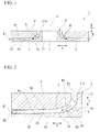
FIG. 1 is a side cross-sectional view schematically illustrating the configuration of an impeller manufactured by a manufacturing method of an impeller according to the present invention. -
FIG. 2 is a partial enlarged view illustrating the impeller inFIG. 1 . -
FIG. 3 is a side cross-sectional view illustrating a manufacturing process of the impeller. -
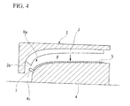
FIG. 4 is a side cross-sectional view illustrating a manufacturing process of an impeller according to a first modified embodiment. -
FIG. 5 is a side cross-sectional view illustrating a manufacturing process of an impeller according to a second modified embodiment. -
FIG. 6 is a side cross-sectional view illustrating a manufacturing process of an impeller according to a third modified embodiment. -
FIG. 7 is a side view illustrating a manufacturing process of an existing impeller. - A manufacturing method of an impeller according to an embodiment of the present invention will be described with reference to
FIGS. 1 to 3 . - Reference numeral 1 in
FIG. 1 denotes an impeller manufactured by the manufacturing method of the impeller according to the embodiment, and the impeller is mounted, as a rotor assembled with the rotation shaft, in a compressor such as a centrifugal compressor. - As illustrated in
FIGS. 1 and 2 , the impeller 1 includes adisc 2 which has a substantially disc shape and is mounted coaxially with a rotation shaft (not shown), plural wing-shaped blades 3 of which ends are fixed to thedisc 2 and which are arranged radially from the center axis O of the rotation shaft, acover 4 which is opposed to thedisc 2 so as to have a space and fixed to the other ends of theblade 3. A space, which is formed between the side surfaces of theblades 3 and the flow surfaces (surfaces opposed to each other) of thedisc 2 and thecover 4, functions as a passage R for gas compressed by the compressor. - In addition, the right side on
FIG. 2 when viewed from the plan view represents an inner peripheral side (on a side toward the center axis O illustrated inFIG. 1 ) of the impeller 1, and the left side represents an outer peripheral side. In addition, inFIGS. 1 and 2 , with regard to a direction (an arrow direction E) in which gas flows in the passage R, the upper side on the plane represents an upstream side, and the lower side on the plane represents a downstream side. In addition, the rotation shaft direction of the impeller 1 is referred to as a Y direction, and similarly the radial direction is referred to as an X direction. This will be commonly applied in the following description. - The
disc 2 forms the outer shape of the impeller 1, is made of metal such as carbon steel or stainless steel, and is constituted by acylindrical portion 21 into which the rotation shaft (not shown) described above is inserted and amain body portion 22 which extends from an end (that is, the lower side from the planes ofFIGS. 1 and 2 ) of thecylindrical portion 21 in the rotation shaft direction Y toward the outer peripheral side in the radial direction X. Thecylindrical portion 21 and themain body portion 22 are formed integrally with each other. Here, in thedisc 2, an upper surface (a side toward the passage R of gas) which is opposed to thecover 4 on the planes illustrated inFIGS. 1 and 2 is referred to as afront surface 2a, and a lower surface opposed thereto is referred to as arear surface 2b in the following description. Thefront surface 2a of themain body portion 22 is curved from the outer peripheral side toward the inner peripheral side so as to gradually protrude in the rotation shaft direction Y toward afront end 21 a of thecylindrical portion 21. That is, on the inner peripheral side of thefront surface 2a of thedisc 2, acurved surface 2d is formed which has a shape that follows a curved portion Ra of the passage R. - Each
blade 3 provided between thedisc 2 and thecover 4 is smoothly curved along thefront surface 2a of thedisc 2 toward the inner peripheral side in the radial direction (the arrow direction X) so as to protrude toward the front end in the rotation shaft direction (the arrow direction Y), and also curved on a side in the circumferential direction of thedisc 2. The curved portion (thecurved surface 3d) has a shape that follows the curved portion Ra of the passage R. - Here, in the
blade 3, an edge disposed toward thedisc 2 is referred to as a disc-side blade edge 3a, and an edge disposed toward thecover 4 is referred to as a cover-side blade edge 3b in the following description. - In this embodiment, the disc-
side blade edge 3a of theblade 3 is formed integrally with thefront surface 2a of thedisc 2, and the cover-side blade edge 3b thereof is bonded to ablade attachment surface 4a of thecover 4 by brazing using a brazing filler metal 5 (bonding material) such as foil, powder, or wire. In addition, the bonding structure is not limited thereto, and in the case where theblade attachment surface 4a of thecover 4 is formed integrally with the cover-side blade edge 3b, a structure may be employed in which the disc-side blade edge 3a is bonded to thefront surface 2a of thedisc 2 by brazing using thebrazing filler metal 5 such as foil, powder, or wire. - The lower surface (the
blade attachment surface 4a) of thecover 4 is integrally fixed to the cover-side blade edge 3b of theblade 3, and curved from the outer peripheral side toward the inner peripheral side in the radial direction (the arrow direction X) so as to protrude toward the front end in the rotation shaft direction Y. That is, on the inner peripheral side of theblade attachment surface 4a of thecover 4, acurved surface 4d is formed which has a shape that follows the curved portion Ra of the passage R. - As described above, between the
adjacent blades 3, the passage R is formed so as to generate compressed air with the rotation of the impeller 1, and the passage R is curved in both the rotation shaft direction Y and the circumferential direction according to the shapes of thedisc 2, theblade 3, and thecover 4. - When the impeller 1 of the compressor, which is configured as described above is driven and rotated by a driving unit (not shown) about the center axis O, there is a flow of air, indicated by the arrow E, from the inner peripheral side to the outer peripheral side in the radial direction in the passage R, and the air is accelerated by centrifugal force generated by the rotation. Accordingly, air sucked from an inlet R1 of the passage R is compressed in the passage R and discharged from an outlet R2, and then sent to an external device (not shown) on the downstream side.
- Next, a manufacturing method of the impeller 1 described above will be described with reference to
FIG. 3 and so on. - First, as illustrated in
FIG. 3 , thedisc 2 is formed integrally with theplural blades 3 by the machining of materials. Aflat surface 4b is placed on the floor (bed) 6 such that theblade attachment surface 4a of thecover 4 faces up, and thebrazing filler metal 5 is disposed on an attachment region of theblade attachment surface 4a of thecover 4, to which theblade 3 is to be attached. Subsequently, in the state where thedisc 2 provided with theblades 3 is positioned on thecover 4, theblade attachment surface 4a of thecover 4 and the cover-side blade edge 3b of theblade 3 are bonded to each other using thebrazing filler metal 5. Thereafter, a step is performed for finishing theflat portion 4b of thecover 4 into a predetermined shape. - Specifically, the
cover 4 is disposed such that theblade attachment surface 4a of thecover 4 faces up, an inner peripheralbond part end 4c of thecover 4 positioned on the curved portion Ra of the passage R is disposed on the lower side of the curved potion Ra, and disposed at a downstream position of thebrazing filler metal 5 that is melted by, for example, heating and liquefied. Accordingly, thebrazing filler metal 5 that is melted during bonding flows toward the inner peripheralbond part end 4c (arrow direction F), so that thecover 4 and theblade 3 can be bonded to each other. That is, at the bond part between theblade 3 and thecover 4, which is a bond part on the inner peripheral side in the radial direction of the impeller 1 (seeFIG. 1 ) on which rotational stress during the impeller operation is concentrated, sufficient supply of thebrazing filler metal 5 is secured. Accordingly, it is possible to avoid the problem of a reduction in bonding strength. - In addition, in this embodiment, the side opposite to the
blade attachment surface 4a of thecover 4 is theflat surface 4b, so that a stable state during the bonding can be achieved by allowing theflat surface 4b to face down. Accordingly, there is an advantage in that thebrazing filler metal 5 uniformly flows toward the inner peripheralbond part end 4c along thecurved surface 4d of thecover 4. - In addition, in this embodiment, during the bonding of the
blade 3 and thecover 4, thebrazing filler metal 5 is disposed on theblade attachment surface 4a of thecover 4. However, the disposition is not limited thereto, and thebrazing filler metal 5 may be attached to the cover-side blade edge 3b of theblade 3. - In the manufacturing method of an impeller according to the first embodiment described above, since the
brazing filler metal 5 is bonded while flowing toward the inner periphery from the bond part of theblade 3 and thecover 4 during bonding, it is possible to prevent an insufficient amount of thebrazing filler metal 5 from being supplied to the inner peripheralbond part end 4c. Therefore, it is possible to ensure the bonding strength at the bond part and increase the reliability of the bond part. - Next, an embodiment modified from the above-mentioned embodiment will be described with reference to the accompanying drawings. Same elements or similar elements of the above-mentioned embodiment are denoted by same reference numerals, and a detailed description thereof will be omitted. Other configurations different from those of the embodiment will be described.
- The first modified embodiment illustrated in
FIG. 4 is different from the manufacturing method of the above-mentioned embodiment in that a protruding portion 7 for preventing spill of thebrazing filler metal 5 is provided on the inner peripheralbond part end 4c of thecover 4 which is positioned at the curved portion Ra of the passage R in the bond part with theblade 3. The protruding portion 7 protrudes from the inner peripheralbond part end 4c of thecover 4 toward thefront surface 2a of thedisc 2, and the length (in a direction perpendicular to the plane) thereof is equal to or greater than the width of theblade 3. The protruding portion 7 is provided during the bonding, and removed along with any excess thickness of thebrazing filler metal 5 after the bonding. As described above, in the first modified embodiment having the protruding portion 7, the flow of thebrazing filler metal 5 is restricted by the protruding portion 7 during the bonding, so that it is possible to reliably prevent the spill of thebrazing filler metal 5. Therefore, there is an advantage in that it is possible to increase the bonding strength of the bond part of thecover 4 and theblade 3. - Next, in the second modified embodiment illustrated in
FIG. 5 , instead of the protruding portion 7 (seeFIG. 4 ) of the above-mentioned first modified embodiment, arecess portion 8 is provided. That is, therecess portion 8 is provided in the inner peripheralbond part end 4c of thecover 4 which is positioned at the curved portion Ra of the passage R in the bond part with theblade 3 so as to allow anopening 8a to face thefront surface 2a of thedisc 2 and has a function of preventing spill of thebrazing filler metal 5 during manufacturing. - The length (in the direction perpendicular to the plane) of the
recess portion 8 is equal to or greater than the width of the blade 3 (or thebrazing filler metal 5 provided on the cover 4). Therecess portion 8 is provided during the bonding. After the bonding, thebrazing filler metal 5 that flows over therecess portion 8 is removed along with any excess thickness of thebrazing filler metal 5 or processed so as to be suitably buried and brought back up. As described above, in the second modified embodiment having therecess portion 8, thebrazing filler metal 5 flows into therecess portion 8 during the bonding, so that the flow thereof can be restricted. Therefore, as in the first modified embodiment described above, it is possible to reliably prevent the spill of thebrazing filler metal 5 and increase the bonding strength of the bond part of thecover 4 and theblade 3. - A third modified embodiment illustrated in
FIG. 6 replaces the manufacturing method of the above-mentioned embodiment. - Specifically, in the manufacturing method of an impeller according to the above-mentioned embodiment, the
blade 3, which is formed integrally with thedisc 2 in advance, is bonded to thecover 4. However, in the third modified embodiment, aflat surface 4b of acover 4 formed integrally with ablade 3 in advance is placed on a floor 6, and in this state, abrazing filler metal 5 is disposed on a disc-side blade edge 3a of theblade 3, and thedisc 2 is disposed on and bonded to the blade 3 (the brazing filler metal 5) using thebrazing filler metal 5. In addition, the position of thebrazing filler metal 5 is not limited to the disc-side blade edge 3a, and thebrazing filler metal 5 may be attached to thefront surface 2a of thedisc 2 so as to bond theblade 3 and thedisc 2 to each other. - In the third modified embodiment, the
cover 4 is disposed such that theblade attachment surface 4a faces up, so that an inner peripheralbond part end 3c of theblade 3 which is positioned at the curved portion Ra of the passage R is disposed on the lower side of the curved portion Ra and on the downstream side of thebrazing filler metal 5 which is melted by, for example, heating and liquefied. Therefore, thebrazing filler metal 5 which is melted during the bonding flows toward the inner peripheralbond part end 3c (in an arrow direction F), so that the two members (thecover 4 and the blade 3) are bonded to each other. That is, at the bond part between theblade 3 and thedisc 2, which is a bond part on the inner peripheral side in the radial direction of the impeller 1 (seeFIG. 1 ) on which rotational stress during the impeller operation is concentrated, as in the above-mentioned embodiment, there are advantages in that insufficiency of thebrazing filler metal 5 does not occur, and the problem of the reduction in the bonding strength can be eliminated. - While the manufacturing method of an impeller according to the embodiments and the modified embodiment of the present invention have been described and illustrated above, it should be understood that the present invention is not limited to the embodiments and the modified embodiments and can be modified without departing from the spirit and scope of the present invention.
- For example, in the embodiment and the modified embodiments, bonding by brazing is employed. However, they are not limited thereto, and for example, transient liquid phase diffusion bonding may be employed.
- In addition, in the embodiment and the modified embodiments, during the bonding, the
cover 4 is configured such that the surface opposite to theblade attachment surface 4a is theflat surface 4b but is not limited to a shape with theflat surface 4b. The point is that in the impeller, thecover 4 may be disposed at a lower position in a stable state during the bonding of the members. Accordingly, during the bonding, the shape of thecover 4 may have an arbitrary finishing shape, and while this is in a stable state, the bonding may be performed. - In addition, the shapes and the sizes of the
disc 2, theblade 3, and thecover 4 may be suitably set. - In addition, in the second modified embodiment, the protruding portion 7 is provided on the inner peripheral
bond part end 4c of thecover 4. However, the position thereof is not limited thereto, and in the case of thecover 4 formed integrally with theblade 3 as in the above-mentioned second modified embodiment (seeFIG. 6 ), a protruding portion protruding toward theblade attachment surface 4a of thecover 4 may be provided on the inner peripheral bond part end at a position attached to theblade 3 in thefront surface 2a of thedisc 2. - While preferred embodiments of the present invention have been described and illustrated above, it should be understood that these are exemplary of the present invention and are not to be considered as limiting. Additions, omissions, substitutions, and other modifications can be made without departing from the spirit or scope of the present invention. Accordingly, the present invention is not to be considered as being limited by the foregoing description, and is only limited by the scope of the appended claims.
Claims (5)
- A manufacturing method of an impeller which includes a disc, a cover opposed to the disc, a plurality of blades provided between the disc and the cover, and a plurality of passages formed between the disc and the cover, each of the passages having an inlet formed on a surface of the cover of the impeller and an outlet formed on an outer peripheral surface of the impeller, and the direction of each of the passages being changed so as to follow a radial direction of the impeller as it proceeds from the inlet to the outlet, the manufacturing method comprising:forming the plurality of blades integrally on a blade attachment surface of one of the disc and the cover;placing the cover on a floor so as to face up the blade attachment surface of the cover;disposing the disc on the cover so as to face down the blade attachment surface of the disc; andbonding the plurality of blades to the blade attachment surface of the other of the disc and the cover which is not formed integrally with the plurality of blades by using a bonding material.
- The manufacturing method according to claim 1, wherein a protruding portion or a recess portion is provided near an inner peripheral bond part end where the passage is curved, in a bond part with the blades, on the blade attachment surface of the cover so as to prevent the bonding material from spilling.
- The manufacturing method according to claim 1, wherein a surface opposite to the blade attachment surface of the cover is made flat, and after the plurality of blades is joined to one of the disc and the cover, the surface opposite to the blade attachment surface of the cover is formed into a predetermined shape.
- The manufacturing method according to claim 2, wherein a surface opposite to the blade attachment surface of the cover is made flat, and after the plurality of blades is joined to one of the disc and the cover, the surface opposite to the blade attachment surface of the cover is formed into a predetermined shape.
- An impeller manufactured by the manufacturing method of an impeller according to any one of claims 1 to 4.
Applications Claiming Priority (1)
| Application Number | Priority Date | Filing Date | Title |
|---|---|---|---|
| JP2009015451A JP4699531B2 (en) | 2009-01-27 | 2009-01-27 | Impeller manufacturing method and impeller |
Publications (2)
| Publication Number | Publication Date |
|---|---|
| EP2216119A1 true EP2216119A1 (en) | 2010-08-11 |
| EP2216119B1 EP2216119B1 (en) | 2016-07-27 |
Family
ID=42269690
Family Applications (1)
| Application Number | Title | Priority Date | Filing Date |
|---|---|---|---|
| EP09174484.7A Active EP2216119B1 (en) | 2009-01-27 | 2009-10-29 | Manufacturing method of impeller |
Country Status (3)
| Country | Link |
|---|---|
| US (1) | US8435005B2 (en) |
| EP (1) | EP2216119B1 (en) |
| JP (1) | JP4699531B2 (en) |
Cited By (2)
| Publication number | Priority date | Publication date | Assignee | Title |
|---|---|---|---|---|
| EP2933440A4 (en) * | 2013-02-18 | 2016-03-30 | Mitsubishi Heavy Ind Ltd | Turbine nozzle and method for manufacturing same |
| EP3053690B1 (en) * | 2015-02-09 | 2024-03-27 | RTX Corporation | Assemblies with brazed joints and methods of fabricating assemblies with brazed joints |
Families Citing this family (14)
| Publication number | Priority date | Publication date | Assignee | Title |
|---|---|---|---|---|
| JP5535878B2 (en) | 2010-11-11 | 2014-07-02 | 三菱重工業株式会社 | Impeller manufacturing method |
| EP2679333B1 (en) * | 2011-02-22 | 2019-05-08 | Mitsubishi Heavy Industries Compressor Corporation | Method of manufacturing impeller |
| JP5606358B2 (en) | 2011-02-24 | 2014-10-15 | 三菱重工業株式会社 | Impeller, rotor provided with the same, and method for manufacturing impeller |
| JP2013047479A (en) | 2011-08-29 | 2013-03-07 | Mitsubishi Heavy Ind Ltd | Impeller and rotary machine with the same, and method for manufacturing impeller |
| JP5907723B2 (en) | 2011-12-26 | 2016-04-26 | 三菱重工業株式会社 | Manufacturing method of rotating machine |
| US20140030099A1 (en) * | 2012-07-27 | 2014-01-30 | GM Global Technology Operations LLC | Pump impeller |
| JP5534084B1 (en) * | 2013-05-29 | 2014-06-25 | ニシジマ精機株式会社 | COG blower runner manufacturing method |
| US9933185B2 (en) * | 2014-02-24 | 2018-04-03 | Noritz Corporation | Fan and water heater provided with the same, and impeller and water heater provided with the same |
| JP7149174B2 (en) * | 2018-12-10 | 2022-10-06 | ダイキン工業株式会社 | Closed impeller and manufacturing method thereof |
| US11473592B2 (en) * | 2019-08-13 | 2022-10-18 | Emerson Climate Technologies, Inc. | Systems and methods for manufacturing a shrouded impeller |
| JP6982267B2 (en) | 2020-05-08 | 2021-12-17 | ダイキン工業株式会社 | Closed impeller and manufacturing method of closed impeller |
| JP7588975B2 (en) * | 2020-06-30 | 2024-11-25 | 三菱重工コンプレッサ株式会社 | Rotary machine impeller and rotary machine |
| WO2022187038A1 (en) * | 2021-03-05 | 2022-09-09 | Danfoss A/S | Techniques for applying brazing material to form a shrouded impeller |
| CN114043182B (en) * | 2021-11-30 | 2022-08-19 | 四川航天中天动力装备有限责任公司 | Method for improving profile correction and machining precision of integrally cast impeller of gas compressor |
Citations (4)
| Publication number | Priority date | Publication date | Assignee | Title |
|---|---|---|---|---|
| JPS6142479A (en) * | 1984-08-02 | 1986-02-28 | Honda Motor Co Ltd | Method of setting brazing filler metal in vane brazing process of impeller |
| DE3831692A1 (en) * | 1988-09-17 | 1989-03-02 | Bbc Brown Boveri & Cie | Method for connecting the cover plate and/or foot piece on the one hand to the blade on the other by means of a brazing or jointing process |
| US20030057263A1 (en) * | 2000-04-28 | 2003-03-27 | Beedon Kent W. | Method of brazing and article made therefrom |
| JP2003328989A (en) | 2002-05-16 | 2003-11-19 | Hitachi Industries Co Ltd | How to make an impeller |
Family Cites Families (6)
| Publication number | Priority date | Publication date | Assignee | Title |
|---|---|---|---|---|
| JPS53109208A (en) * | 1977-03-04 | 1978-09-22 | Hitachi Ltd | Manufacturing process of brazed runner |
| SU1373883A1 (en) * | 1986-01-17 | 1988-02-15 | Производственное объединение "Невский завод" им.В.И.Ленина | Centrifugal compressor impeller |
| JPH05202701A (en) * | 1992-01-28 | 1993-08-10 | Mitsubishi Heavy Ind Ltd | Joining method |
| FR2703111B1 (en) * | 1993-03-25 | 1995-06-30 | Ozen Sa | ROTOR FOR PUMP COMPRISING TWO WELDED ASSEMBLIES, OBTAINED BY INJECTION MOLDING OF THERMOPLASTIC MATERIALS, AND METHOD FOR MANUFACTURING SUCH A ROTOR. |
| JPH08159088A (en) * | 1994-12-06 | 1996-06-18 | Ishikawajima Harima Heavy Ind Co Ltd | Impeller manufacturing method |
| JP2002364588A (en) * | 2001-06-05 | 2002-12-18 | Hitachi Ltd | Impeller and method of manufacturing the same |
-
2009
- 2009-01-27 JP JP2009015451A patent/JP4699531B2/en active Active
- 2009-10-29 EP EP09174484.7A patent/EP2216119B1/en active Active
- 2009-10-29 US US12/608,359 patent/US8435005B2/en active Active
Patent Citations (4)
| Publication number | Priority date | Publication date | Assignee | Title |
|---|---|---|---|---|
| JPS6142479A (en) * | 1984-08-02 | 1986-02-28 | Honda Motor Co Ltd | Method of setting brazing filler metal in vane brazing process of impeller |
| DE3831692A1 (en) * | 1988-09-17 | 1989-03-02 | Bbc Brown Boveri & Cie | Method for connecting the cover plate and/or foot piece on the one hand to the blade on the other by means of a brazing or jointing process |
| US20030057263A1 (en) * | 2000-04-28 | 2003-03-27 | Beedon Kent W. | Method of brazing and article made therefrom |
| JP2003328989A (en) | 2002-05-16 | 2003-11-19 | Hitachi Industries Co Ltd | How to make an impeller |
Cited By (2)
| Publication number | Priority date | Publication date | Assignee | Title |
|---|---|---|---|---|
| EP2933440A4 (en) * | 2013-02-18 | 2016-03-30 | Mitsubishi Heavy Ind Ltd | Turbine nozzle and method for manufacturing same |
| EP3053690B1 (en) * | 2015-02-09 | 2024-03-27 | RTX Corporation | Assemblies with brazed joints and methods of fabricating assemblies with brazed joints |
Also Published As
| Publication number | Publication date |
|---|---|
| US8435005B2 (en) | 2013-05-07 |
| JP2010174652A (en) | 2010-08-12 |
| JP4699531B2 (en) | 2011-06-15 |
| US20100189568A1 (en) | 2010-07-29 |
| EP2216119B1 (en) | 2016-07-27 |
Similar Documents
| Publication | Publication Date | Title |
|---|---|---|
| US8435005B2 (en) | Manufacturing method of impeller | |
| US20100196163A1 (en) | Method of manufacturing impeller, impeller, and compressor having impeller | |
| US8899931B2 (en) | Impeller, compressor, and method for producing impeller | |
| JP5550812B2 (en) | Turbine blade device | |
| CN103097739B (en) | Impeller, possess the rotating machinery of this impeller and the manufacture method of impeller | |
| EP2395246A1 (en) | Impeller, compressor, and impeller fabrication method | |
| US11879476B2 (en) | Closed impeller and method for producing closed impeller | |
| CN102741007B (en) | Method of performing beam welding of two-passage impellers on slots; impellers and turbomachinery having such welded configurations | |
| EP2789860B1 (en) | Shroud impeller of centrifugal compressor and method of manufacturing the same | |
| CN102625881B (en) | Method for manufacturing impeller | |
| CN114258461B (en) | Method for manufacturing a shrouded impeller, shrouded impeller and compressor | |
| CN107250553A (en) | Impeller and method of manufacturing such impeller | |
| EP2679826A1 (en) | Impeller, rotor comprising same, and impeller manufacturing method | |
| JP2009275513A (en) | Impeller, compressor using impeller and method for manufacturing impeller | |
| WO2015076217A1 (en) | Impeller, rotary machine, and impeller manufacturing method | |
| CN112997008A (en) | Impeller, pump having the same, and method for manufacturing the same | |
| JP2004036444A (en) | Method for manufacturing impeller with shroud | |
| JP5007457B2 (en) | Turbo fan | |
| KR102509054B1 (en) | Rotor assembly | |
| JP2000213493A (en) | Impeller and manufacture thereof | |
| JP6202731B2 (en) | Assembly method of impeller | |
| KR20150088641A (en) | Impeller and manufacturing method the same | |
| JP2017198158A (en) | Impeller and pump with impeller | |
| KR20130117142A (en) | Impeller and manufacturing method thereof |
Legal Events
| Date | Code | Title | Description |
|---|---|---|---|
| PUAI | Public reference made under article 153(3) epc to a published international application that has entered the european phase |
Free format text: ORIGINAL CODE: 0009012 |
|
| AK | Designated contracting states |
Kind code of ref document: A1 Designated state(s): AT BE BG CH CY CZ DE DK EE ES FI FR GB GR HR HU IE IS IT LI LT LU LV MC MK MT NL NO PL PT RO SE SI SK SM TR |
|
| 17P | Request for examination filed |
Effective date: 20101216 |
|
| 17Q | First examination report despatched |
Effective date: 20120601 |
|
| GRAP | Despatch of communication of intention to grant a patent |
Free format text: ORIGINAL CODE: EPIDOSNIGR1 |
|
| INTG | Intention to grant announced |
Effective date: 20160316 |
|
| RAP1 | Party data changed (applicant data changed or rights of an application transferred) |
Owner name: MITSUBISHI HEAVY INDUSTRIES, LTD. |
|
| GRAS | Grant fee paid |
Free format text: ORIGINAL CODE: EPIDOSNIGR3 |
|
| GRAA | (expected) grant |
Free format text: ORIGINAL CODE: 0009210 |
|
| AK | Designated contracting states |
Kind code of ref document: B1 Designated state(s): AT BE BG CH CY CZ DE DK EE ES FI FR GB GR HR HU IE IS IT LI LT LU LV MC MK MT NL NO PL PT RO SE SI SK SM TR |
|
| REG | Reference to a national code |
Ref country code: GB Ref legal event code: FG4D |
|
| REG | Reference to a national code |
Ref country code: CH Ref legal event code: EP |
|
| REG | Reference to a national code |
Ref country code: AT Ref legal event code: REF Ref document number: 815382 Country of ref document: AT Kind code of ref document: T Effective date: 20160815 |
|
| REG | Reference to a national code |
Ref country code: IE Ref legal event code: FG4D |
|
| REG | Reference to a national code |
Ref country code: DE Ref legal event code: R096 Ref document number: 602009039938 Country of ref document: DE |
|
| REG | Reference to a national code |
Ref country code: FR Ref legal event code: PLFP Year of fee payment: 8 |
|
| REG | Reference to a national code |
Ref country code: LT Ref legal event code: MG4D |
|
| REG | Reference to a national code |
Ref country code: NL Ref legal event code: MP Effective date: 20160727 |
|
| REG | Reference to a national code |
Ref country code: AT Ref legal event code: MK05 Ref document number: 815382 Country of ref document: AT Kind code of ref document: T Effective date: 20160727 |
|
| PG25 | Lapsed in a contracting state [announced via postgrant information from national office to epo] |
Ref country code: FI Free format text: LAPSE BECAUSE OF FAILURE TO SUBMIT A TRANSLATION OF THE DESCRIPTION OR TO PAY THE FEE WITHIN THE PRESCRIBED TIME-LIMIT Effective date: 20160727 Ref country code: LT Free format text: LAPSE BECAUSE OF FAILURE TO SUBMIT A TRANSLATION OF THE DESCRIPTION OR TO PAY THE FEE WITHIN THE PRESCRIBED TIME-LIMIT Effective date: 20160727 Ref country code: NL Free format text: LAPSE BECAUSE OF FAILURE TO SUBMIT A TRANSLATION OF THE DESCRIPTION OR TO PAY THE FEE WITHIN THE PRESCRIBED TIME-LIMIT Effective date: 20160727 Ref country code: HR Free format text: LAPSE BECAUSE OF FAILURE TO SUBMIT A TRANSLATION OF THE DESCRIPTION OR TO PAY THE FEE WITHIN THE PRESCRIBED TIME-LIMIT Effective date: 20160727 Ref country code: IS Free format text: LAPSE BECAUSE OF FAILURE TO SUBMIT A TRANSLATION OF THE DESCRIPTION OR TO PAY THE FEE WITHIN THE PRESCRIBED TIME-LIMIT Effective date: 20161127 Ref country code: NO Free format text: LAPSE BECAUSE OF FAILURE TO SUBMIT A TRANSLATION OF THE DESCRIPTION OR TO PAY THE FEE WITHIN THE PRESCRIBED TIME-LIMIT Effective date: 20161027 |
|
| PG25 | Lapsed in a contracting state [announced via postgrant information from national office to epo] |
Ref country code: AT Free format text: LAPSE BECAUSE OF FAILURE TO SUBMIT A TRANSLATION OF THE DESCRIPTION OR TO PAY THE FEE WITHIN THE PRESCRIBED TIME-LIMIT Effective date: 20160727 Ref country code: LV Free format text: LAPSE BECAUSE OF FAILURE TO SUBMIT A TRANSLATION OF THE DESCRIPTION OR TO PAY THE FEE WITHIN THE PRESCRIBED TIME-LIMIT Effective date: 20160727 Ref country code: ES Free format text: LAPSE BECAUSE OF FAILURE TO SUBMIT A TRANSLATION OF THE DESCRIPTION OR TO PAY THE FEE WITHIN THE PRESCRIBED TIME-LIMIT Effective date: 20160727 Ref country code: SE Free format text: LAPSE BECAUSE OF FAILURE TO SUBMIT A TRANSLATION OF THE DESCRIPTION OR TO PAY THE FEE WITHIN THE PRESCRIBED TIME-LIMIT Effective date: 20160727 Ref country code: PT Free format text: LAPSE BECAUSE OF FAILURE TO SUBMIT A TRANSLATION OF THE DESCRIPTION OR TO PAY THE FEE WITHIN THE PRESCRIBED TIME-LIMIT Effective date: 20161128 Ref country code: BE Free format text: LAPSE BECAUSE OF NON-PAYMENT OF DUE FEES Effective date: 20160727 Ref country code: GR Free format text: LAPSE BECAUSE OF FAILURE TO SUBMIT A TRANSLATION OF THE DESCRIPTION OR TO PAY THE FEE WITHIN THE PRESCRIBED TIME-LIMIT Effective date: 20161028 Ref country code: PL Free format text: LAPSE BECAUSE OF FAILURE TO SUBMIT A TRANSLATION OF THE DESCRIPTION OR TO PAY THE FEE WITHIN THE PRESCRIBED TIME-LIMIT Effective date: 20160727 |
|
| PG25 | Lapsed in a contracting state [announced via postgrant information from national office to epo] |
Ref country code: RO Free format text: LAPSE BECAUSE OF FAILURE TO SUBMIT A TRANSLATION OF THE DESCRIPTION OR TO PAY THE FEE WITHIN THE PRESCRIBED TIME-LIMIT Effective date: 20160727 Ref country code: EE Free format text: LAPSE BECAUSE OF FAILURE TO SUBMIT A TRANSLATION OF THE DESCRIPTION OR TO PAY THE FEE WITHIN THE PRESCRIBED TIME-LIMIT Effective date: 20160727 |
|
| REG | Reference to a national code |
Ref country code: DE Ref legal event code: R097 Ref document number: 602009039938 Country of ref document: DE |
|
| PG25 | Lapsed in a contracting state [announced via postgrant information from national office to epo] |
Ref country code: DK Free format text: LAPSE BECAUSE OF FAILURE TO SUBMIT A TRANSLATION OF THE DESCRIPTION OR TO PAY THE FEE WITHIN THE PRESCRIBED TIME-LIMIT Effective date: 20160727 Ref country code: SK Free format text: LAPSE BECAUSE OF FAILURE TO SUBMIT A TRANSLATION OF THE DESCRIPTION OR TO PAY THE FEE WITHIN THE PRESCRIBED TIME-LIMIT Effective date: 20160727 Ref country code: BG Free format text: LAPSE BECAUSE OF FAILURE TO SUBMIT A TRANSLATION OF THE DESCRIPTION OR TO PAY THE FEE WITHIN THE PRESCRIBED TIME-LIMIT Effective date: 20161027 Ref country code: SM Free format text: LAPSE BECAUSE OF FAILURE TO SUBMIT A TRANSLATION OF THE DESCRIPTION OR TO PAY THE FEE WITHIN THE PRESCRIBED TIME-LIMIT Effective date: 20160727 Ref country code: CZ Free format text: LAPSE BECAUSE OF FAILURE TO SUBMIT A TRANSLATION OF THE DESCRIPTION OR TO PAY THE FEE WITHIN THE PRESCRIBED TIME-LIMIT Effective date: 20160727 |
|
| REG | Reference to a national code |
Ref country code: CH Ref legal event code: PL |
|
| PLBE | No opposition filed within time limit |
Free format text: ORIGINAL CODE: 0009261 |
|
| STAA | Information on the status of an ep patent application or granted ep patent |
Free format text: STATUS: NO OPPOSITION FILED WITHIN TIME LIMIT |
|
| GBPC | Gb: european patent ceased through non-payment of renewal fee |
Effective date: 20161029 |
|
| 26N | No opposition filed |
Effective date: 20170502 |
|
| REG | Reference to a national code |
Ref country code: IE Ref legal event code: MM4A |
|
| PG25 | Lapsed in a contracting state [announced via postgrant information from national office to epo] |
Ref country code: LI Free format text: LAPSE BECAUSE OF NON-PAYMENT OF DUE FEES Effective date: 20161031 Ref country code: GB Free format text: LAPSE BECAUSE OF NON-PAYMENT OF DUE FEES Effective date: 20161029 Ref country code: CH Free format text: LAPSE BECAUSE OF NON-PAYMENT OF DUE FEES Effective date: 20161031 |
|
| PG25 | Lapsed in a contracting state [announced via postgrant information from national office to epo] |
Ref country code: SI Free format text: LAPSE BECAUSE OF FAILURE TO SUBMIT A TRANSLATION OF THE DESCRIPTION OR TO PAY THE FEE WITHIN THE PRESCRIBED TIME-LIMIT Effective date: 20160727 Ref country code: LU Free format text: LAPSE BECAUSE OF NON-PAYMENT OF DUE FEES Effective date: 20161029 |
|
| REG | Reference to a national code |
Ref country code: FR Ref legal event code: PLFP Year of fee payment: 9 |
|
| PG25 | Lapsed in a contracting state [announced via postgrant information from national office to epo] |
Ref country code: IE Free format text: LAPSE BECAUSE OF NON-PAYMENT OF DUE FEES Effective date: 20161029 |
|
| PG25 | Lapsed in a contracting state [announced via postgrant information from national office to epo] |
Ref country code: HU Free format text: LAPSE BECAUSE OF FAILURE TO SUBMIT A TRANSLATION OF THE DESCRIPTION OR TO PAY THE FEE WITHIN THE PRESCRIBED TIME-LIMIT; INVALID AB INITIO Effective date: 20091029 Ref country code: CY Free format text: LAPSE BECAUSE OF FAILURE TO SUBMIT A TRANSLATION OF THE DESCRIPTION OR TO PAY THE FEE WITHIN THE PRESCRIBED TIME-LIMIT Effective date: 20160727 |
|
| PG25 | Lapsed in a contracting state [announced via postgrant information from national office to epo] |
Ref country code: TR Free format text: LAPSE BECAUSE OF FAILURE TO SUBMIT A TRANSLATION OF THE DESCRIPTION OR TO PAY THE FEE WITHIN THE PRESCRIBED TIME-LIMIT Effective date: 20160727 Ref country code: MK Free format text: LAPSE BECAUSE OF FAILURE TO SUBMIT A TRANSLATION OF THE DESCRIPTION OR TO PAY THE FEE WITHIN THE PRESCRIBED TIME-LIMIT Effective date: 20160727 Ref country code: MT Free format text: LAPSE BECAUSE OF NON-PAYMENT OF DUE FEES Effective date: 20161031 Ref country code: MC Free format text: LAPSE BECAUSE OF FAILURE TO SUBMIT A TRANSLATION OF THE DESCRIPTION OR TO PAY THE FEE WITHIN THE PRESCRIBED TIME-LIMIT Effective date: 20160727 |
|
| REG | Reference to a national code |
Ref country code: FR Ref legal event code: PLFP Year of fee payment: 10 |
|
| PGFP | Annual fee paid to national office [announced via postgrant information from national office to epo] |
Ref country code: IT Payment date: 20250922 Year of fee payment: 17 |
|
| PGFP | Annual fee paid to national office [announced via postgrant information from national office to epo] |
Ref country code: FR Payment date: 20250908 Year of fee payment: 17 |
|
| PGFP | Annual fee paid to national office [announced via postgrant information from national office to epo] |
Ref country code: DE Payment date: 20250902 Year of fee payment: 17 |