EP2216105A1 - Procédé de nettoyage et de séchage d'une pièce usinée et système pour la mise en oeuvre du procédé - Google Patents
Procédé de nettoyage et de séchage d'une pièce usinée et système pour la mise en oeuvre du procédé Download PDFInfo
- Publication number
- EP2216105A1 EP2216105A1 EP10150978A EP10150978A EP2216105A1 EP 2216105 A1 EP2216105 A1 EP 2216105A1 EP 10150978 A EP10150978 A EP 10150978A EP 10150978 A EP10150978 A EP 10150978A EP 2216105 A1 EP2216105 A1 EP 2216105A1
- Authority
- EP
- European Patent Office
- Prior art keywords
- rotation
- axes
- workpiece
- drying
- machined part
- Prior art date
- Legal status (The legal status is an assumption and is not a legal conclusion. Google has not performed a legal analysis and makes no representation as to the accuracy of the status listed.)
- Granted
Links
- 238000001035 drying Methods 0.000 title claims abstract description 36
- 238000000034 method Methods 0.000 title claims abstract description 33
- 238000004140 cleaning Methods 0.000 title claims abstract description 31
- 238000005119 centrifugation Methods 0.000 claims abstract description 18
- 238000003754 machining Methods 0.000 claims description 27
- 238000005406 washing Methods 0.000 claims description 19
- 238000004519 manufacturing process Methods 0.000 claims description 4
- 238000006073 displacement reaction Methods 0.000 abstract description 3
- 239000007788 liquid Substances 0.000 description 10
- 238000005520 cutting process Methods 0.000 description 8
- 230000033001 locomotion Effects 0.000 description 8
- 239000002173 cutting fluid Substances 0.000 description 6
- 238000010981 drying operation Methods 0.000 description 3
- 238000001704 evaporation Methods 0.000 description 3
- 230000008020 evaporation Effects 0.000 description 3
- 238000009434 installation Methods 0.000 description 2
- XLYOFNOQVPJJNP-UHFFFAOYSA-N water Substances O XLYOFNOQVPJJNP-UHFFFAOYSA-N 0.000 description 2
- 230000005540 biological transmission Effects 0.000 description 1
- 238000005266 casting Methods 0.000 description 1
- 238000005238 degreasing Methods 0.000 description 1
- 239000003599 detergent Substances 0.000 description 1
- 239000004519 grease Substances 0.000 description 1
- 238000010438 heat treatment Methods 0.000 description 1
- 229910052751 metal Inorganic materials 0.000 description 1
- 239000002184 metal Substances 0.000 description 1
- 238000011084 recovery Methods 0.000 description 1
- UONOETXJSWQNOL-UHFFFAOYSA-N tungsten carbide Chemical compound [W+]#[C-] UONOETXJSWQNOL-UHFFFAOYSA-N 0.000 description 1
Images

Classifications
-
- B—PERFORMING OPERATIONS; TRANSPORTING
- B08—CLEANING
- B08B—CLEANING IN GENERAL; PREVENTION OF FOULING IN GENERAL
- B08B7/00—Cleaning by methods not provided for in a single other subclass or a single group in this subclass
- B08B7/02—Cleaning by methods not provided for in a single other subclass or a single group in this subclass by distortion, beating, or vibration of the surface to be cleaned
-
- B—PERFORMING OPERATIONS; TRANSPORTING
- B23—MACHINE TOOLS; METAL-WORKING NOT OTHERWISE PROVIDED FOR
- B23Q—DETAILS, COMPONENTS, OR ACCESSORIES FOR MACHINE TOOLS, e.g. ARRANGEMENTS FOR COPYING OR CONTROLLING; MACHINE TOOLS IN GENERAL CHARACTERISED BY THE CONSTRUCTION OF PARTICULAR DETAILS OR COMPONENTS; COMBINATIONS OR ASSOCIATIONS OF METAL-WORKING MACHINES, NOT DIRECTED TO A PARTICULAR RESULT
- B23Q1/00—Members which are comprised in the general build-up of a form of machine, particularly relatively large fixed members
- B23Q1/25—Movable or adjustable work or tool supports
- B23Q1/44—Movable or adjustable work or tool supports using particular mechanisms
- B23Q1/50—Movable or adjustable work or tool supports using particular mechanisms with rotating pairs only, the rotating pairs being the first two elements of the mechanism
- B23Q1/54—Movable or adjustable work or tool supports using particular mechanisms with rotating pairs only, the rotating pairs being the first two elements of the mechanism two rotating pairs only
- B23Q1/5406—Movable or adjustable work or tool supports using particular mechanisms with rotating pairs only, the rotating pairs being the first two elements of the mechanism two rotating pairs only a single rotating pair followed perpendicularly by a single rotating pair
- B23Q1/5412—Movable or adjustable work or tool supports using particular mechanisms with rotating pairs only, the rotating pairs being the first two elements of the mechanism two rotating pairs only a single rotating pair followed perpendicularly by a single rotating pair followed perpendicularly by a single rotating pair
-
- B—PERFORMING OPERATIONS; TRANSPORTING
- B23—MACHINE TOOLS; METAL-WORKING NOT OTHERWISE PROVIDED FOR
- B23Q—DETAILS, COMPONENTS, OR ACCESSORIES FOR MACHINE TOOLS, e.g. ARRANGEMENTS FOR COPYING OR CONTROLLING; MACHINE TOOLS IN GENERAL CHARACTERISED BY THE CONSTRUCTION OF PARTICULAR DETAILS OR COMPONENTS; COMBINATIONS OR ASSOCIATIONS OF METAL-WORKING MACHINES, NOT DIRECTED TO A PARTICULAR RESULT
- B23Q11/00—Accessories fitted to machine tools for keeping tools or parts of the machine in good working condition or for cooling work; Safety devices specially combined with or arranged in, or specially adapted for use in connection with, machine tools
- B23Q11/0042—Devices for removing chips
-
- F—MECHANICAL ENGINEERING; LIGHTING; HEATING; WEAPONS; BLASTING
- F26—DRYING
- F26B—DRYING SOLID MATERIALS OR OBJECTS BY REMOVING LIQUID THEREFROM
- F26B5/00—Drying solid materials or objects by processes not involving the application of heat
- F26B5/08—Drying solid materials or objects by processes not involving the application of heat by centrifugal treatment
Definitions
- the present invention relates to a method for cleaning and drying a machined part, in particular an automobile part such as a motor cylinder head.
- the machining of a part is performed on a machining line by a series of operations.
- the operations include for example machining operations, assembly operations and parts washing / drying operations.
- the assembly operations allow for example to mount on a main part already machined components that must be machined once in place on this main part.
- the machining line generally comprises two assembly operations: a first for assembling guides and valve seats crude and a second to assemble by screwing the bearing caps that hold the camshafts.
- the machined parts that come out of machining operations are dirty: they are covered with chips and cutting liquid. Also, before assembly, the machined parts are cleaned and dried by passing through a washing / drying operation. However, the machines carrying out the washing / drying operation are particularly cumbersome. Indeed, the drying is carried out by evaporation, which implies a long length necessary for conveying the pieces until they are dry and at room temperature. In addition, the drying by evaporation is a long and very energy consuming process since it is necessary to heat slightly (approximately 45 ° C) the parts so that the water evaporates.
- the document FR-A-2,151,722 discloses a metal chip wringer comprising a frustoconical perforated drum of horizontal or substantially horizontal axis.
- the frustoconical perforated drum is connected, on the side of its small base, to a supply of chips to be dewatered and, on the side of its large base, to a drained chip evacuation.
- the wringer is alternately driven by a rapid rotational movement and a slow rotational movement within and over an oil recovery casing.
- EP-A-1460256 discloses a method of assembling a camshaft support. A washing operation is planned at the end to remove the chips.
- US-A-2006 0168806 discloses a method of machining castings with a tungsten carbide cutting tool that does not require the use of a cutting fluid.
- the invention provides a method for cleaning and drying a workpiece by setting the machined part in motion.
- the movement of the machined part is selected from centrifugation, rotational vibration, translational vibration, alternating linear displacements.
- the centrifugation comprises the rotation of the workpiece around at least two axes of rotation, preferably three axes, inclined relative to each other, preferably perpendicular to each other.
- the rotations of the workpiece around the various axes of rotation are performed simultaneously.
- the rotations of the machined part around the various axes of rotation are successively carried out, the method comprising a change of attachment of the machined part between rotations made around different axes of rotation.
- the centrifugation time around each axis of rotation is between 20 and 30 seconds.
- the speed of rotation of the workpiece around each axis of rotation is between 300 and 1500 revolutions per minute.
- the present invention also relates to a method for manufacturing an automobile part, comprising a step of machining the workpiece, a step of cleaning and drying the workpiece according to the method defined above and, a washing step of the workpiece before, or during a part of, the cleaning and drying step.
- the present invention further relates to a cleaning and drying system of a machined part for the implementation of the method defined above, comprising rotational drive members of the machined part so as to clean and dry the workpiece machined by centrifugation.
- the rotational drive members are adapted to rotate the workpiece about at least two axes of rotation, preferably three axes inclined relative to each other, preferably perpendicular to each other. other.
- the rotary drive members are adapted to rotate the machined part simultaneously around the different axes of rotation.
- the rotary drive members are adapted to rotate the machined part successively around the different axes of rotation.
- system further comprises a device for washing the part.
- the subject of the invention is also a machining machine comprising a cleaning and drying system as defined above and in which the axes of rotation are axes of the machining machine.
- the invention relates to a method for cleaning and drying a workpiece by setting the machined part in motion.
- the machining chips and the cutting liquid are removed. This ensures efficient and fast cleaning (by chip evacuation) and efficient and fast drying (by evacuation of the cutting fluid). In addition, the cleaning and drying are performed without heating, which allows energy savings. Finally, the process is compact to implement since a conveyance is no longer necessary for drying.
- the movement of the machined part is selected from centrifugation, rotational vibration, translational vibration, alternative linear displacements.
- Centrifugation involves rotating the workpiece around at least two axes of rotation. These axes of rotation are inclined relative to each other. The machined part is thus rotated about two different axes not parallel to each other. This helps to remove chips and cutting fluid more efficiently.
- the axes of rotation are preferably three in number, which is even more effective than a rotation about two axes.
- the axes of rotation can be of a number greater than three, for example if the part is very complex.
- the axes of rotation are preferably perpendicular to each other. This is particularly useful for example if the part has perpendicular axes between them.
- the axes of rotation are preferably axes of the machined part.
- a cylinder head for example, is substantially parallelepipedic. It comprises a longitudinal axis and two axes which are respectively according to the width and thickness of the cylinder head. These three axes are perpendicular to each other. The rotational drive of a cylinder head around these three axes makes it particularly effective and quick to remove chips and cutting fluid due to machining.
- the rotations of the machined part around the different axes of rotation are performed simultaneously.
- the process is particularly fast.
- it is compact to implement since a single device like that of the figure 1 , detailed below, makes it possible to implement the method.
- the machined part undergoes a change of fixation between rotations made around different axes of rotation.
- the machined part is for example mounted successively on the same axis of rotation of a single device but successively aligning different axes of the part on the axis of rotation of the device, in order to rotate the machined part successively around the different selected axes of the room.
- the machined part may, alternatively, be mounted successively on as many devices as there are axes of rotation. Each of the devices will then cause the workpiece rotated about an axis of rotation inclined relative to the axes of rotation of the other devices.
- the centrifugation time around each axis of rotation is between 20 and 30 seconds.
- the total duration of the centrifugation is between 20 and 30 seconds.
- the cleaning and drying process is then very fast.
- the total duration of centrifugation is then between 60 and 90 seconds, which is also much faster than drying by evaporation.
- the rotational speed of the workpiece around each axis of rotation is between 300 and 1500 revolutions per minute. This speed range is used to evacuate chips and cutting fluid.
- the durations and speeds of rotation vary in particular according to the geometry of the workpiece.
- An automobile part such as for example a motor cylinder head, is manufactured in the following manner.
- the automotive part undergoes at least one machining operation. After each machining operation, the automobile part is cleaned and dried by the cleaning and drying process described above. After a machining operation, the automotive part is greasy because of the cutting liquid containing grease.
- the automobile part is thus washed with washing liquid to degrease it, then is cleaned and dried according to the method described above.
- This washing operation can be performed after each machining operation, but it is preferably performed only after the last machining operation so as to save time and washing liquid, as explained below.
- the washing step can be performed before the last cleaning and drying step.
- the washing step is performed during a portion of the cleaning and drying step, preferably at the beginning to be able to dry the part properly during the end of the cleaning and drying step.
- the figure 1 is a sectional view of an exemplary cleaning and drying system 1.
- the system comprises means 2-4 for rotating the workpiece 10 so as to clean and dry the workpiece by centrifugation.
- the system is compact and allows the machined part to be cleaned and dried quickly.
- the rotational drive members 2-4 are adapted to rotate the workpiece about at least two axes of rotation, preferably three axes inclined relative to one another, preferably perpendicular to one another. . This makes it possible to evacuate the chips and the cutting liquid more efficiently, as explained above for the process.
- the members 2-4 drive the part in rotation about two axes 8, 9 perpendicular to each other.
- the rotating drive members 2-4 may be adapted to rotate the machined part simultaneously around the different axes of rotation. This makes it possible to clean and dry the machined part 11 in a fast and compact manner since a single device makes it possible to implement the method described above.
- the machined part 10 is held on a frame 11. It is mounted on the members 3, 4, which are on the axes 8, 9 of rotation, which are rotated by one or more motors.
- a single motor 2 drives the members 3, 4 in rotation.
- One of the rotational drive members 3 is connected directly to the motor.
- the other member 4 is connected to the motor via a device 5-7 for transmitting the force of the engine 2.
- This transmission device 5-7 comprises a rod 5 connected to the output of the engine 2.
- This rod 5 ends with a toothed wheel 6 meshing with a toothed wheel 7 of the body 4.
- the system may comprise several motors, each motor driving a different axis of rotation.
- the rotational member 3 can be held entirely by the frame 11 or be maintained between the frame 11 and a tailstock 15.
- FIGS. 2a and 2b represent sectional views of system 1 of the figure 1 mounted on a housing 12 respectively open and closed.
- the chassis 11 of the system of the figure 1 is mounted hinged on a housing 12.
- a cover 13 adapted to close the housing, as shown on the figure 2b , to prevent splashes of chips and cutting fluid from the housing.
- the cover 13 is fixed to the frame 11.
- the system 1 In the open position ( figure 2a ), the system 1 is in place of the cover. This makes it easy to position the machined part on the system 1.
- the system 1 and the cover 13 are tilted through the frame 11, so as to that the system 1 is in the housing and that the lid 13 closes the housing.
- the rotary drive members can then be started to clean and dry the workpiece 10.
- the system may also comprise rotational drive members adapted to rotate the machined part successively around the different axes of rotation.
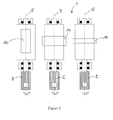
- the figure 3 represents a sectional view of such an example of a cleaning and drying system, with successive rotations.
- the system 1 comprises three devices for rotating the machined part 10.
- the system 1 could comprise only two devices, if rotations around only two axes of rotation are necessary.
- Each of the devices drives the machined part about an axis 8, 9, 18 of different rotation. Between each device, the part is changed fixing.
- the axes 8, 9 and 18 are parallel to each other.
- the machined part is mounted on each of these devices with a different axis of the part aligned with the axis of rotation 8, 9 and 18. From the point of view of the workpiece, it thus rotates well around three perpendicular axes between them.
- the system may further include a part washing device for degreasing the machined part, preferably at the end of the machining line.
- the invention also relates to a machining machine comprising the cleaning and drying system described above, in which the axes of rotation are axes of the machining machine.
Landscapes
- Engineering & Computer Science (AREA)
- Mechanical Engineering (AREA)
- Health & Medical Sciences (AREA)
- Life Sciences & Earth Sciences (AREA)
- Molecular Biology (AREA)
- General Engineering & Computer Science (AREA)
- Cleaning By Liquid Or Steam (AREA)
- Treatment Of Fiber Materials (AREA)
- Accessory Of Washing/Drying Machine, Commercial Washing/Drying Machine, Other Washing/Drying Machine (AREA)
- Drying Of Solid Materials (AREA)
- Manufacturing Of Printed Wiring (AREA)
Abstract
Description
- La présente invention concerne un procédé de nettoyage et de séchage d'une pièce usinée, en particulier d'une pièce automobile telle qu'une culasse de moteur.
- L'usinage d'une pièce est réalisé sur une ligne d'usinage par une suite d'opérations. Les opérations comprennent par exemple des opérations d'usinage, des opérations d'assemblage et des opérations de lavage/séchage des pièces.
- Les opérations d'assemblage permettent par exemple de monter sur une pièce principale déjà usinée des composants qui doivent être usinés une fois en place sur cette pièce principale. Pour une culasse, la ligne d'usinage comprend généralement deux opérations d'assemblage : une première pour assembler des guides et des sièges de soupapes bruts et une deuxième pour assembler par vissage des chapeaux de paliers qui tiennent les arbres à cames.
- Les pièces usinées qui sortent des opérations d'usinage sont sales : elles sont recouvertes de copeaux et liquide de coupe. Aussi, avant assemblage, les pièces usinées sont nettoyées et séchées par passage par une opération de lavage/séchage. Toutefois, les machines réalisant l'opération de lavage/séchage sont particulièrement encombrantes. En effet, le séchage est réalisé par évaporation, ce qui implique une longueur importante nécessaire au convoyage des pièces jusqu'à ce qu'elles soient sèches et à température ambiante. De plus, le séchage par évaporation est un processus long et très gourmand en énergie puisqu'il faut chauffer légèrement (environ 45°C) les pièces pour que l'eau s'évapore.
- Le document
FR-A-2 151 722 - Le document
EP-A-1 460 256 décrit un procédé d'assemblage d'un support arbre à cames. Une opération de lavage est prévue à la fin pour enlever les copeaux. - Le document
US-A-2006 0168806 décrit un procédé d'usinage de pièces de fonderie avec un outil de coupe en carbure de tungstène ne nécessitant pas l'emploi d'un fluide de coupe. - Toutefois aucun des documents n'enseigne de procédé de nettoyage et de séchage d'une pièce usinée qui réponde aux inconvénients cités plus haut.
- Il y a donc un besoin pour un procédé de nettoyage et de séchage de pièces usinées qui soit peu encombrant à mettre en oeuvre, qui permette un nettoyage et un séchage rapides et qui soit économe en énergie.
- Pour cela, l'invention propose un procédé de nettoyage et de séchage d'une pièce usinée par mise en mouvement de la pièce usinée.
- Dans une variante, la mise en mouvement de la pièce usinée est choisie parmi la centrifugation, la vibration en rotation, la vibration en translation, les déplacements linéaires alternatifs.
- Dans une variante, la centrifugation comprend la rotation de la pièce usinée autour d'au moins deux axes de rotation, de préférence trois axes, inclinés les uns par rapport aux autres, de préférence perpendiculaires les uns par rapport aux autres.
- Avantageusement, les rotations de la pièce usinée autour des différents axes de rotation sont réalisées simultanément.
- Avantageusement, les rotations de la pièce usinée autour des différents axes de rotation sont réalisées successivement, le procédé comprenant un changement de fixation de la pièce usinée entre des rotations effectuées autour d'axes de rotation différents.
- Avantageusement, la durée de centrifugation autour de chaque axe de rotation est comprise entre 20 et 30 secondes.
- Avantageusement, la vitesse de rotation de la pièce usinée autour de chaque axe de rotation est comprise entre 300 et 1500 tours par minute.
- La présente invention a également pour objet un procédé de fabrication d'une pièce automobile, comprenant une étape d'usinage de la pièce, une étape de nettoyage et de séchage de la pièce usinée selon le procédé défini précédemment et, une étape de lavage de la pièce usinée avant, ou pendant une partie de, l'étape de nettoyage et de séchage.
- La présente invention a par ailleurs pour objet un système de nettoyage et de séchage d'une pièce usinée pour la mise en oeuvre du procédé défini précédemment, comprenant des organes d'entraînement en rotation de la pièce usinée de façon à nettoyer et sécher la pièce usinée par centrifugation.
- Dans une variante, les organes d'entraînement en rotation sont adaptés à entraîner en rotation la pièce autour d'au moins deux axes de rotation, de préférence trois axes, inclinés les uns par rapport aux autres, de préférence perpendiculaires les uns par rapport aux autres.
- Dans une variante, les organes d'entraînement en rotation sont adaptés à entraîner en rotation la pièce usinée simultanément autour des différents axes de rotation.
- Dans une variante, les organes d'entraînement en rotation sont adaptés à entraîner en rotation la pièce usinée successivement autour des différents axes de rotation.
- Dans une variante, le système comprend en outre un dispositif de lavage de la pièce.
- L'invention a également pour objet une machine d'usinage comprenant un système de nettoyage et séchage tel que défini précédemment et dans laquelle les axes de rotation sont des axes de la machine d'usinage.
- D'autres caractéristiques et avantages de l'invention apparaîtront à la lecture de la description détaillée qui suit des modes de réalisation de l'invention, donnés à titre d'exemple uniquement et en références aux dessins qui montrent :
-
figure 1 , une vue en coupe d'un exemple de système de nettoyage et de séchage ; -
figures 2a et 2b , des vues en coupe du système de lafigure 1 , monté sur un carter respectivement ouvert et fermé ; -
figure 3 , une vue en coupe d'un autre exemple de système de nettoyage et de séchage. - L'invention se rapporte à un procédé de nettoyage et de séchage d'une pièce usinée par mise en mouvement de la pièce usinée.
- Pendant la mise en mouvement de la pièce usinée, les copeaux d'usinage et le liquide de coupe sont évacués. Ainsi, un nettoyage (par évacuation des copeaux) et un séchage (par évacuation du liquide de coupe) efficaces et rapides sont effectués. De plus, le nettoyage et le séchage sont réalisés sans chauffage, ce qui permet de réaliser des économies d'énergie. Enfin, le procédé est peu encombrant à mettre en oeuvre puisqu'un convoyage n'est plus nécessaire pour le séchage.
- La mise en mouvement de la pièce usinée est choisie parmi la centrifugation, la vibration en rotation, la vibration en translation, les déplacements linéaires alternatifs.
- L'ensemble de ces exemples de mise en mouvement permet en effet d'évacuer rapidement et efficacement les copeaux d'usinage et le liquide de coupe, de façon économique en énergie et de façon peu encombrante.
- La suite de la description, ainsi que les exemples illustrés sur les figures concernent plus particulièrement la centrifugation, sans que cela soit à comprendre comme une limitation.
- La centrifugation comprend la rotation de la pièce usinée autour d'au moins deux axes de rotation. Ces axes de rotation sont inclinés les uns par rapport aux autres. La pièce usinée est ainsi soumise à une rotation autour de deux axes différents non parallèles entre eux. Cela permet d'évacuer les copeaux et le liquide de coupe plus efficacement.
- Les axes de rotation sont de préférence au nombre de trois, ce qui est encore plus efficace qu'une rotation autour de deux axes.
- Les axes de rotation peuvent être d'un nombre supérieur à trois, par exemple si la pièce est très complexe.
- Les axes de rotation sont de préférence perpendiculaires les uns par rapport aux autres. Cela est particulièrement utile par exemple si la pièce a des axes perpendiculaires entre eux.
- Les axes de rotation sont de préférence des axes de la pièce usinée. Ainsi, le nettoyage et le séchage de la pièce usinée, réalisés par centrifugation, sont plus efficaces. Une culasse, par exemple, est sensiblement parallélépipédique. Elle comprend un axe longitudinal et deux axes qui sont respectivement selon la largeur et l'épaisseur de la culasse. Ces trois axes sont perpendiculaires entre eux. L'entraînement en rotation d'une culasse autour de ces trois axes permet d'évacuer particulièrement efficacement et rapidement les copeaux et le liquide de coupe dus à l'usinage.
- Dans un mode de réalisation préféré, illustré en particulier sur la
figure 1 , les rotations de la pièce usinée autour des différents axes de rotation sont réalisées simultanément. De cette façon, le procédé est particulièrement rapide. De plus, il est peu encombrant à mettre en oeuvre puisqu'un unique dispositif comme celui de lafigure 1 , détaillé plus loin, permet de mettre en oeuvre le procédé. - En variante, les rotations de la pièce usinée autour des différents axes de rotation sont réalisées successivement.
- Dans cette variante, la pièce usinée subit un changement de fixation entre des rotations effectuées autour d'axes de rotation différents.
- Ainsi, la pièce usinée est par exemple montée successivement sur le même axe de rotation d'un unique dispositif mais en alignant successivement des axes différents de la pièce sur l'axe de rotation du dispositif, afin de faire tourner la pièce usinée successivement autour des différents axes sélectionnés de la pièce. Cela permet de mettre en oeuvre le procédé sur un dispositif simple à fabriquer.
- La pièce usinée peut, de façon alternative, être montée successivement sur autant de dispositifs qu'il y a d'axes de rotations. Chacun des dispositifs entraînera alors la pièce usinée en rotation autour d'un axe de rotation incliné par rapport aux axes de rotation des autres dispositifs.
- Afin d'assurer l'évacuation des copeaux et du liquide de coupe, la durée de centrifugation autour de chaque axe de rotation est comprise entre 20 et 30 secondes. Lorsque les rotations autour des différents axes de rotation sont réalisées simultanément, la durée totale de la centrifugation est comprise entre 20 et 30 secondes. Le procédé de nettoyage et de séchage est alors très rapide. Lorsque trois rotations sont réalisées successivement, la durée totale de centrifugation est alors comprise entre 60 et 90 secondes, ce qui est également beaucoup plus rapide qu'un séchage par évaporation.
- La vitesse de rotation de la pièce usinée autour de chaque axe de rotation est comprise entre 300 et 1500 tours par minute. Cette gamme de vitesse permet d'évacuer les copeaux et le liquide de coupe.
- Les durées et vitesses de rotation varient en particulier en fonction de la géométrie de la pièce à usiner.
- Une pièce automobile, telle que par exemple une culasse de moteur, est fabriquée de la façon suivante. La pièce automobile subit au moins une opération d'usinage. Après chaque opération d'usinage, la pièce automobile est nettoyée et séchée par le procédé de nettoyage et de séchage décrit plus haut. Après une opération d'usinage, la pièce automobile est grasse du fait du liquide de coupe contenant de la graisse. La pièce automobile est donc lavée avec du liquide lessiviel pour la dégraisser, puis est nettoyée et séchée selon le procédé décrit plus haut. Cette opération de lavage peut être réalisée après chaque opération d'usinage, mais elle est de préférence réalisée uniquement après la dernière opération d'usinage de façon à économiser du temps et du liquide lessiviel, comme expliqué plus bas.
- L'étape de lavage peut être réalisée avant la dernière étape de nettoyage et de séchage. En variante, l'étape de lavage est réalisée pendant une partie de l'étape de nettoyage et de séchage, de préférence au début pour pouvoir sécher la pièce correctement pendant la fin de l'étape de nettoyage et de séchage.
- Le fait d'avoir une unique étape de lavage en fin de ligne d'usinage est particulièrement avantageux. Cela permet d'avoir une installation de lavage simple et peu coûteuse. Cela permet également de réduire la durée de fabrication de la pièce.
- En effet, dans l'état de l'art, il est connu de laver la pièce après chaque étape d'usinage, ce qui oblige à prévoir une centrale et un réseau de liquide lessiviel en plus de la centrale et du réseau de liquide de coupe, ce qui entraîne une complexité et un coût important de l'installation. En outre, le lavage s'effectuant à l'eau chaude pour dégraisser, la température en sortie de la machine de lavage/séchage est élevée, ce qui oblige à temporiser la suite des opérations dans la ligne d'usinage.
- En revanche, lorsqu'une unique étape de lavage est présente en fin de ligne d'usinage, comme décrit ici, la temporisation pour refroidir ne pénalise pas pour la suite des opérations puisque l'usinage est terminé.
- Un système de nettoyage et de séchage d'une pièce usinée pour la mise en oeuvre du procédé décrit ci-dessus va maintenant être décrit.
- Les références qui sont identiques sur les différentes figures représentent des éléments identiques ou similaires.
- La
figure 1 représente une vue en coupe d'un exemple de système 1 de nettoyage et de séchage. - Le système comprend des organes 2-4 d'entraînement en rotation de la pièce usinée 10 de façon à nettoyer et sécher la pièce usinée par centrifugation. Le système est peu encombrant et permet de nettoyer et sécher rapidement la pièce usinée.
- Les organes 2-4 d'entraînement en rotation sont adaptés à entraîner en rotation la pièce autour d'au moins deux axes de rotation, de préférence trois axes, inclinés les uns par rapport aux autres, de préférence perpendiculaires les uns par rapport aux autres. Cela permet d'évacuer les copeaux et le liquide de coupe plus efficacement, comme expliqué plus haut pour le procédé.
- Sur l'exemple particulier de la
figure 1 , les organes 2-4 entraînent la pièce en rotation autour de deux axes 8, 9 perpendiculaires entre eux. - Comme représenté sur la
figure 1 , les organes 2-4 d'entraînement en rotation peuvent être adaptés à entraîner en rotation la pièce usinée simultanément autour des différents axes de rotation. Cela permet de nettoyer et sécher la pièce usinée 11 de façon rapide et peu encombrante puisqu'un unique dispositif permet de mettre en oeuvre le procédé décrit plus haut. - La pièce usinée 10 est maintenue sur un châssis 11. Elle est monté sur les organes 3, 4, qui sont sur les axes 8, 9 de rotation, qui sont entraînés en rotation par un ou plusieurs moteurs.
- Sur l'exemple de la
figure 1 , un unique moteur 2 entraîne les organes 3, 4 en rotation. Un des organes 3 d'entraînement en rotation est relié directement au moteur. L'autre organe 4 est relié au moteur via un dispositif 5-7 de transmission de la force du moteur 2. Ce dispositif 5-7 de transmission comprend une tige 5 reliée à la sortie du moteur 2. Cette tige 5 se termine par une roue dentée 6 engrenant sur une roue dentée 7 de l'organe 4. - En variante, le système peut comprendre plusieurs moteurs, chaque moteur entraînant un axe de rotation différent.
- L'organe de rotation 3 peut être maintenu entièrement par le châssis 11 ou être maintenu entre le châssis 11 et une contrepointe 15.
- Les
figures 2a et 2b représentent des vues en coupe du système 1 de lafigure 1 , monté sur un carter 12 respectivement ouvert et fermé. Le châssis 11 du système de lafigure 1 est monté articulé sur un carter 12. Un couvercle 13 adapté à fermer le carter, comme représenté sur lafigure 2b , pour éviter les projections de copeaux et de liquide de coupe hors du carter. Le couvercle 13 est fixé au châssis 11. En position ouverte (figure 2a ), le système 1 est à la place du couvercle. Cela permet de positionner facilement la pièce usinée sur le système 1. Une fois la pièce usinée 10 fixée sur les organes 3, 4 du système 1, le système 1 et le couvercle 13 sont basculés par l'intermédiaire du châssis 11, de façon à ce que le système 1 se trouve dans le carter et que le couvercle 13 ferme le carter. Les organes d'entraînement en rotation peuvent alors être mis en route pour nettoyer et sécher la pièce usinée 10. - Le système peut également comprendre des organes d'entraînement en rotation adaptés à entraîner en rotation la pièce usinée successivement autour des différents axes de rotation.
- La
figure 3 représente une vue en coupe d'un tel exemple de système de nettoyage et de séchage, avec des rotations successives. - Le système 1 comprend trois dispositifs d'entraînement en rotation de la pièce usinée 10. Le système 1 pourrait ne comprendre que deux dispositifs, si des rotations autour de seulement deux axes de rotations sont nécessaires. Chacun des dispositifs entraînent la pièce usinée autour d'un axe 8, 9, 18 de rotation différent. Entre chaque dispositif, la pièce est changée de fixation.
- Sur la
figure 3 , les axes 8, 9 et 18 sont parallèles entre eux. Toutefois, la pièce usinée est montée sur chacun de ces dispositifs avec un axe de la pièce différents aligné avec l'axe de rotation 8, 9 et 18. Du point de vue de la pièce usinée, celle-ci tourne donc bien autour de trois axes perpendiculaires entre eux. - En variante de la
figure 3 , les rotations successives peuvent avoir lieu sur un unique dispositif comme expliqué plus haut, dans la partie concernant le procédé. - Le système peut en outre comprendre un dispositif de lavage de la pièce afin de dégraisser la pièce usinée, de préférence en fin de ligne d'usinage.
- L'invention concerne également une machine d'usinage comprenant le système de nettoyage et séchage décrit plus haut, dans laquelle les axes de rotation sont des axes de la machine d'usinage.
Claims (12)
- Procédé de nettoyage et de séchage d'une pièce usinée par mise en mouvement par centrifugation de la pièce usinée, dans lequel la centrifugation comprend la rotation de la pièce usinée autour d'au moins deux axes de rotation, de préférence trois axes, inclinés les uns par rapport aux autres, de préférence perpendiculaires les uns par rapport aux autres.
- Procédé selon la revendication 1, dans lequel les rotations de la pièce usinée autour des différents axes de rotation sont réalisées simultanément.
- Procédé selon la revendication 2, dans lequel les rotations de la pièce usinée autour des différents axes de rotation sont réalisées successivement, le procédé comprenant un changement de fixation de la pièce usinée entre des rotations effectuées autour d'axes de rotation différents.
- Procédé selon l'une des revendications 1 à 3, dans lequel la durée de centrifugation autour de chaque axe de rotation est comprise entre 20 et 30 secondes.
- Procédé selon l'une des revendications 1 à 4, dans lequel la vitesse de rotation de la pièce usinée autour de chaque axe de rotation est comprise entre 300 et 1500 tours par minute.
- Procédé de fabrication d'une pièce automobile, comprenant une étape d'usinage de la pièce, une étape de nettoyage et de séchage de la pièce usinée selon le procédé selon l'une des revendications 1 à 5 et, une étape de lavage de la pièce usinée avant, ou pendant une partie de, l'étape de nettoyage et de séchage.
- Système (1) de nettoyage et de séchage d'une pièce usinée pour la mise en oeuvre du procédé selon l'une des revendications 1 à 5, comprenant des organes d'entraînement (2-4) en rotation de la pièce usinée de façon à nettoyer et sécher la pièce usinée par centrifugation.
- Système (1) selon la revendication 7, dans lequel les organes d'entraînement en rotation sont adaptés à entraîner en rotation la pièce autour d'au moins deux axes de rotation (8, 9, 18), de préférence trois axes, inclinés les uns par rapport aux autres, de préférence perpendiculaires les uns par rapport aux autres.
- Système (1) selon la revendication 7 ou la revendication 8, dans lequel les organes d'entraînement en rotation sont adaptés à entraîner en rotation la pièce usinée simultanément autour des différents axes de rotation.
- Système (1) selon la revendication 7 ou la revendication 8, dans lequel les organes d'entraînement en rotation sont adaptés à entraîner en rotation la pièce usinée successivement autour des différents axes de rotation.
- Système (1) selon l'une des revendications 7 à 10, comprenant en outre un dispositif de lavage de la pièce.
- Machine d'usinage comprenant le système de nettoyage et séchage selon l'une des revendications 7 à 11, dans laquelle les axes de rotation sont des axes de la machine d'usinage.
Applications Claiming Priority (1)
| Application Number | Priority Date | Filing Date | Title |
|---|---|---|---|
| FR0950700A FR2941633B1 (fr) | 2009-02-05 | 2009-02-05 | Procede de nettoyage et de sechage d'une piece usinee et systeme pour la mise en oeuvre du procede. |
Publications (2)
| Publication Number | Publication Date |
|---|---|
| EP2216105A1 true EP2216105A1 (fr) | 2010-08-11 |
| EP2216105B1 EP2216105B1 (fr) | 2011-08-10 |
Family
ID=41066473
Family Applications (1)
| Application Number | Title | Priority Date | Filing Date |
|---|---|---|---|
| EP10150978A Ceased EP2216105B1 (fr) | 2009-02-05 | 2010-01-18 | Procédé de nettoyage et de séchage d'une pièce usinée et système pour la mise en oeuvre du procédé |
Country Status (3)
| Country | Link |
|---|---|
| EP (1) | EP2216105B1 (fr) |
| AT (1) | ATE519547T1 (fr) |
| FR (1) | FR2941633B1 (fr) |
Cited By (3)
| Publication number | Priority date | Publication date | Assignee | Title |
|---|---|---|---|---|
| ITUA20161768A1 (it) * | 2016-03-17 | 2017-09-17 | Sortec S R L | Un impianto di pulizia |
| WO2020152587A1 (fr) * | 2019-01-24 | 2020-07-30 | 3M Innovative Properties Company | Dispositif de rotation d'une pièce |
| US12268567B2 (en) | 2019-09-12 | 2025-04-08 | Solventum Intellectual Properties Company | Apparatus, system, method of post-curing an article, and post-cured article |
Families Citing this family (1)
| Publication number | Priority date | Publication date | Assignee | Title |
|---|---|---|---|---|
| CN119778995A (zh) * | 2023-10-05 | 2025-04-08 | 杉野机械股份有限公司 | 离心干燥方法以及离心干燥机 |
Citations (9)
| Publication number | Priority date | Publication date | Assignee | Title |
|---|---|---|---|---|
| FR2151722A5 (en) | 1971-09-10 | 1973-04-20 | Anvar | Centrifugal cleaner - removing cutting oil from metal turnings etc |
| DE3814014A1 (de) * | 1988-04-26 | 1989-11-09 | Werner & Pfleiderer | Verfahren und vorrichtung zum reinigen von verschmutzten werkstuecken |
| WO1990002002A1 (fr) * | 1988-08-26 | 1990-03-08 | Bacra Technology Pty Ltd | Appareil de mise en rotation bi-axiale pour conteneurs aux normes iso |
| DE10150594C1 (de) * | 2001-10-12 | 2002-09-05 | Fraunhofer Ges Forschung | Vorrichtung zum Vibrationstrocknen und Verfahren |
| DE10153087A1 (de) * | 2001-10-30 | 2003-05-22 | Klaus Doehrer | Verfahren zum Entfernen von an einem Werkstück anhaftenden Verunreinigungen in Form von Ölen, Fetten oder Emulsionen mit darin enthaltenen festen Partikeln, und Vorrichtung zur Durchführung des Verfahrens |
| EP1460256A1 (fr) | 2003-03-20 | 2004-09-22 | Nissan Motor Company, Limited | Moteur à combustion interne et cadre intégré de paliers pour arbre à cames de moteur à combustion interne |
| DE10312023B3 (de) * | 2003-03-18 | 2004-09-30 | Döhrer, Klaus, Dipl.-Ing. | Reinigungsvorrichtung für Werkstücke |
| DE10336390A1 (de) * | 2003-08-06 | 2005-03-03 | Fraunhofer-Gesellschaft zur Förderung der angewandten Forschung e.V. | Verfahren zum Lösen von an einem Werkstück haftenden Verunreinigungen und Vorrichtung zur Durchführung des Verfahrens |
| US20060168806A1 (en) | 2004-07-28 | 2006-08-03 | Ang Carolina C | Dry machining of aluminum castings |
-
2009
- 2009-02-05 FR FR0950700A patent/FR2941633B1/fr not_active Expired - Fee Related
-
2010
- 2010-01-18 EP EP10150978A patent/EP2216105B1/fr not_active Ceased
- 2010-01-18 AT AT10150978T patent/ATE519547T1/de not_active IP Right Cessation
Patent Citations (9)
| Publication number | Priority date | Publication date | Assignee | Title |
|---|---|---|---|---|
| FR2151722A5 (en) | 1971-09-10 | 1973-04-20 | Anvar | Centrifugal cleaner - removing cutting oil from metal turnings etc |
| DE3814014A1 (de) * | 1988-04-26 | 1989-11-09 | Werner & Pfleiderer | Verfahren und vorrichtung zum reinigen von verschmutzten werkstuecken |
| WO1990002002A1 (fr) * | 1988-08-26 | 1990-03-08 | Bacra Technology Pty Ltd | Appareil de mise en rotation bi-axiale pour conteneurs aux normes iso |
| DE10150594C1 (de) * | 2001-10-12 | 2002-09-05 | Fraunhofer Ges Forschung | Vorrichtung zum Vibrationstrocknen und Verfahren |
| DE10153087A1 (de) * | 2001-10-30 | 2003-05-22 | Klaus Doehrer | Verfahren zum Entfernen von an einem Werkstück anhaftenden Verunreinigungen in Form von Ölen, Fetten oder Emulsionen mit darin enthaltenen festen Partikeln, und Vorrichtung zur Durchführung des Verfahrens |
| DE10312023B3 (de) * | 2003-03-18 | 2004-09-30 | Döhrer, Klaus, Dipl.-Ing. | Reinigungsvorrichtung für Werkstücke |
| EP1460256A1 (fr) | 2003-03-20 | 2004-09-22 | Nissan Motor Company, Limited | Moteur à combustion interne et cadre intégré de paliers pour arbre à cames de moteur à combustion interne |
| DE10336390A1 (de) * | 2003-08-06 | 2005-03-03 | Fraunhofer-Gesellschaft zur Förderung der angewandten Forschung e.V. | Verfahren zum Lösen von an einem Werkstück haftenden Verunreinigungen und Vorrichtung zur Durchführung des Verfahrens |
| US20060168806A1 (en) | 2004-07-28 | 2006-08-03 | Ang Carolina C | Dry machining of aluminum castings |
Cited By (7)
| Publication number | Priority date | Publication date | Assignee | Title |
|---|---|---|---|---|
| ITUA20161768A1 (it) * | 2016-03-17 | 2017-09-17 | Sortec S R L | Un impianto di pulizia |
| WO2020152587A1 (fr) * | 2019-01-24 | 2020-07-30 | 3M Innovative Properties Company | Dispositif de rotation d'une pièce |
| CN113302040A (zh) * | 2019-01-24 | 2021-08-24 | 3M创新有限公司 | 用于旋转工件的装置 |
| JP2022517843A (ja) * | 2019-01-24 | 2022-03-10 | スリーエム イノベイティブ プロパティズ カンパニー | ワークピースを回転させるためのデバイス |
| CN113302040B (zh) * | 2019-01-24 | 2023-11-17 | 3M创新有限公司 | 用于旋转工件的装置 |
| US11998957B2 (en) | 2019-01-24 | 2024-06-04 | Solventum Intellectual Properties Company | Device for spinning a workpiece |
| US12268567B2 (en) | 2019-09-12 | 2025-04-08 | Solventum Intellectual Properties Company | Apparatus, system, method of post-curing an article, and post-cured article |
Also Published As
| Publication number | Publication date |
|---|---|
| EP2216105B1 (fr) | 2011-08-10 |
| ATE519547T1 (de) | 2011-08-15 |
| FR2941633B1 (fr) | 2011-03-18 |
| FR2941633A1 (fr) | 2010-08-06 |
Similar Documents
| Publication | Publication Date | Title |
|---|---|---|
| EP2216105B1 (fr) | Procédé de nettoyage et de séchage d'une pièce usinée et système pour la mise en oeuvre du procédé | |
| FR3018712A1 (fr) | Outil de percage a deux moteurs coaxiaux | |
| EP3983170B1 (fr) | Broche a actionneurs piezoelectriques | |
| FR2634409A1 (fr) | Procede pour fabriquer un arbre de sortie rotatif | |
| FR3042816A1 (fr) | Moteur thermique muni d'un systeme de variation du taux de compression | |
| EP0113419B1 (fr) | Procédé et dispositif de tronçonnage d'une pièce tubulaire de grand diamètre en matériau rigide notamment à section ovalisée, telle qu'un tuyau en fonte | |
| CH641391A5 (fr) | Machine-outil. | |
| WO2016087731A1 (fr) | Dispositif d'indexation relative des cannelures d'un arbre primaire d'une boite de vitesses et d'un moyeu central d'un embrayage de moteur pour vehicule automobile | |
| WO2006136716A1 (fr) | Element de positionnement et de maintien d’un stator de moteur electrique dans un compresseur, compresseur et procede de montage | |
| WO2014195647A1 (fr) | Dispositif d'usinage vibratoire | |
| FR3034585A1 (fr) | Liaison entre un arbre de machine electrique et un reducteur | |
| FR2757791A1 (fr) | Dispositif d'usinage muni d'une table rotative | |
| FR2759928A1 (fr) | Machine pour la coupe de tubes | |
| EP0918580A1 (fr) | Dispositif pour deplacer une partie d'une machine et exercer un effort en fin de course | |
| EP0952898B1 (fr) | Dispositif pour effectuer, dans un tube, une decoupe dans un plan | |
| EP4084922A1 (fr) | Electro-broche a avance integree avec changement automatique de porte-outil | |
| CH333276A (fr) | Machine-outil comprenant un tambour-revolver | |
| BE367839A (fr) | ||
| FR2804890A1 (fr) | Dispositif de percage radial pour tour | |
| CH668206A5 (en) | Multi-purpose machine tool - has tool table supporting two or more tools which can be rotated at widely-differing speeds through drives and control unit | |
| FR2751901A1 (fr) | Machine-outil d'usinage des sieges de soupapes combine avec l'alesage des guides et son dispositif de synchronisation de securite | |
| FR2606310A1 (fr) | Machine-outil multifonction | |
| FR2578468A1 (fr) | Machine pour la finition de pieces diverses comprenant un dispositif de rattrapage d'usure de l'outil de finition | |
| EP3227049A1 (fr) | Électrobroche munie d'un système rotatif de commande d'un outil ou d'un porte-outil | |
| FR2709998A1 (fr) | Dispositif de brossage rotatif. |
Legal Events
| Date | Code | Title | Description |
|---|---|---|---|
| PUAI | Public reference made under article 153(3) epc to a published international application that has entered the european phase |
Free format text: ORIGINAL CODE: 0009012 |
|
| AK | Designated contracting states |
Kind code of ref document: A1 Designated state(s): AT BE BG CH CY CZ DE DK EE ES FI FR GB GR HR HU IE IS IT LI LT LU LV MC MK MT NL NO PL PT RO SE SI SK SM TR |
|
| AX | Request for extension of the european patent |
Extension state: AL BA RS |
|
| GRAP | Despatch of communication of intention to grant a patent |
Free format text: ORIGINAL CODE: EPIDOSNIGR1 |
|
| 17P | Request for examination filed |
Effective date: 20110112 |
|
| RIC1 | Information provided on ipc code assigned before grant |
Ipc: B23Q 11/00 20060101ALI20110127BHEP Ipc: B08B 7/02 20060101AFI20110127BHEP Ipc: F26B 5/08 20060101ALI20110127BHEP |
|
| GRAS | Grant fee paid |
Free format text: ORIGINAL CODE: EPIDOSNIGR3 |
|
| GRAA | (expected) grant |
Free format text: ORIGINAL CODE: 0009210 |
|
| AK | Designated contracting states |
Kind code of ref document: B1 Designated state(s): AT BE BG CH CY CZ DE DK EE ES FI FR GB GR HR HU IE IS IT LI LT LU LV MC MK MT NL NO PL PT RO SE SI SK SM TR |
|
| REG | Reference to a national code |
Ref country code: GB Ref legal event code: FG4D Free format text: NOT ENGLISH |
|
| REG | Reference to a national code |
Ref country code: CH Ref legal event code: EP |
|
| REG | Reference to a national code |
Ref country code: IE Ref legal event code: FG4D Free format text: LANGUAGE OF EP DOCUMENT: FRENCH |
|
| REG | Reference to a national code |
Ref country code: DE Ref legal event code: R096 Ref document number: 602010000136 Country of ref document: DE Effective date: 20111006 |
|
| REG | Reference to a national code |
Ref country code: DE Ref legal event code: R084 Ref document number: 602010000136 Country of ref document: DE |
|
| REG | Reference to a national code |
Ref country code: NL Ref legal event code: VDEP Effective date: 20110810 |
|
| REG | Reference to a national code |
Ref country code: GB Ref legal event code: 746 Effective date: 20111128 |
|
| REG | Reference to a national code |
Ref country code: DE Ref legal event code: R084 Ref document number: 602010000136 Country of ref document: DE Effective date: 20111119 |
|
| LTIE | Lt: invalidation of european patent or patent extension |
Effective date: 20110810 |
|
| PG25 | Lapsed in a contracting state [announced via postgrant information from national office to epo] |
Ref country code: SE Free format text: LAPSE BECAUSE OF FAILURE TO SUBMIT A TRANSLATION OF THE DESCRIPTION OR TO PAY THE FEE WITHIN THE PRESCRIBED TIME-LIMIT Effective date: 20110810 Ref country code: IS Free format text: LAPSE BECAUSE OF FAILURE TO SUBMIT A TRANSLATION OF THE DESCRIPTION OR TO PAY THE FEE WITHIN THE PRESCRIBED TIME-LIMIT Effective date: 20111210 Ref country code: FI Free format text: LAPSE BECAUSE OF FAILURE TO SUBMIT A TRANSLATION OF THE DESCRIPTION OR TO PAY THE FEE WITHIN THE PRESCRIBED TIME-LIMIT Effective date: 20110810 Ref country code: NL Free format text: LAPSE BECAUSE OF FAILURE TO SUBMIT A TRANSLATION OF THE DESCRIPTION OR TO PAY THE FEE WITHIN THE PRESCRIBED TIME-LIMIT Effective date: 20110810 Ref country code: LT Free format text: LAPSE BECAUSE OF FAILURE TO SUBMIT A TRANSLATION OF THE DESCRIPTION OR TO PAY THE FEE WITHIN THE PRESCRIBED TIME-LIMIT Effective date: 20110810 Ref country code: NO Free format text: LAPSE BECAUSE OF FAILURE TO SUBMIT A TRANSLATION OF THE DESCRIPTION OR TO PAY THE FEE WITHIN THE PRESCRIBED TIME-LIMIT Effective date: 20111110 Ref country code: HR Free format text: LAPSE BECAUSE OF FAILURE TO SUBMIT A TRANSLATION OF THE DESCRIPTION OR TO PAY THE FEE WITHIN THE PRESCRIBED TIME-LIMIT Effective date: 20110810 Ref country code: PT Free format text: LAPSE BECAUSE OF FAILURE TO SUBMIT A TRANSLATION OF THE DESCRIPTION OR TO PAY THE FEE WITHIN THE PRESCRIBED TIME-LIMIT Effective date: 20111212 |
|
| REG | Reference to a national code |
Ref country code: AT Ref legal event code: MK05 Ref document number: 519547 Country of ref document: AT Kind code of ref document: T Effective date: 20110810 |
|
| PG25 | Lapsed in a contracting state [announced via postgrant information from national office to epo] |
Ref country code: LV Free format text: LAPSE BECAUSE OF FAILURE TO SUBMIT A TRANSLATION OF THE DESCRIPTION OR TO PAY THE FEE WITHIN THE PRESCRIBED TIME-LIMIT Effective date: 20110810 Ref country code: AT Free format text: LAPSE BECAUSE OF FAILURE TO SUBMIT A TRANSLATION OF THE DESCRIPTION OR TO PAY THE FEE WITHIN THE PRESCRIBED TIME-LIMIT Effective date: 20110810 Ref country code: CY Free format text: LAPSE BECAUSE OF FAILURE TO SUBMIT A TRANSLATION OF THE DESCRIPTION OR TO PAY THE FEE WITHIN THE PRESCRIBED TIME-LIMIT Effective date: 20110810 Ref country code: SI Free format text: LAPSE BECAUSE OF FAILURE TO SUBMIT A TRANSLATION OF THE DESCRIPTION OR TO PAY THE FEE WITHIN THE PRESCRIBED TIME-LIMIT Effective date: 20110810 Ref country code: PL Free format text: LAPSE BECAUSE OF FAILURE TO SUBMIT A TRANSLATION OF THE DESCRIPTION OR TO PAY THE FEE WITHIN THE PRESCRIBED TIME-LIMIT Effective date: 20110810 Ref country code: GR Free format text: LAPSE BECAUSE OF FAILURE TO SUBMIT A TRANSLATION OF THE DESCRIPTION OR TO PAY THE FEE WITHIN THE PRESCRIBED TIME-LIMIT Effective date: 20111111 |
|
| REG | Reference to a national code |
Ref country code: IE Ref legal event code: FD4D |
|
| PG25 | Lapsed in a contracting state [announced via postgrant information from national office to epo] |
Ref country code: IE Free format text: LAPSE BECAUSE OF FAILURE TO SUBMIT A TRANSLATION OF THE DESCRIPTION OR TO PAY THE FEE WITHIN THE PRESCRIBED TIME-LIMIT Effective date: 20110810 Ref country code: SK Free format text: LAPSE BECAUSE OF FAILURE TO SUBMIT A TRANSLATION OF THE DESCRIPTION OR TO PAY THE FEE WITHIN THE PRESCRIBED TIME-LIMIT Effective date: 20110810 Ref country code: CZ Free format text: LAPSE BECAUSE OF FAILURE TO SUBMIT A TRANSLATION OF THE DESCRIPTION OR TO PAY THE FEE WITHIN THE PRESCRIBED TIME-LIMIT Effective date: 20110810 |
|
| PG25 | Lapsed in a contracting state [announced via postgrant information from national office to epo] |
Ref country code: RO Free format text: LAPSE BECAUSE OF FAILURE TO SUBMIT A TRANSLATION OF THE DESCRIPTION OR TO PAY THE FEE WITHIN THE PRESCRIBED TIME-LIMIT Effective date: 20110810 Ref country code: EE Free format text: LAPSE BECAUSE OF FAILURE TO SUBMIT A TRANSLATION OF THE DESCRIPTION OR TO PAY THE FEE WITHIN THE PRESCRIBED TIME-LIMIT Effective date: 20110810 Ref country code: IT Free format text: LAPSE BECAUSE OF FAILURE TO SUBMIT A TRANSLATION OF THE DESCRIPTION OR TO PAY THE FEE WITHIN THE PRESCRIBED TIME-LIMIT Effective date: 20110810 |
|
| PLBE | No opposition filed within time limit |
Free format text: ORIGINAL CODE: 0009261 |
|
| STAA | Information on the status of an ep patent application or granted ep patent |
Free format text: STATUS: NO OPPOSITION FILED WITHIN TIME LIMIT |
|
| PG25 | Lapsed in a contracting state [announced via postgrant information from national office to epo] |
Ref country code: DK Free format text: LAPSE BECAUSE OF FAILURE TO SUBMIT A TRANSLATION OF THE DESCRIPTION OR TO PAY THE FEE WITHIN THE PRESCRIBED TIME-LIMIT Effective date: 20110810 |
|
| 26N | No opposition filed |
Effective date: 20120511 |
|
| BERE | Be: lapsed |
Owner name: PEUGEOT CITROEN AUTOMOBILES SA Effective date: 20120131 |
|
| PG25 | Lapsed in a contracting state [announced via postgrant information from national office to epo] |
Ref country code: MC Free format text: LAPSE BECAUSE OF NON-PAYMENT OF DUE FEES Effective date: 20120131 |
|
| REG | Reference to a national code |
Ref country code: DE Ref legal event code: R097 Ref document number: 602010000136 Country of ref document: DE Effective date: 20120511 |
|
| PG25 | Lapsed in a contracting state [announced via postgrant information from national office to epo] |
Ref country code: BE Free format text: LAPSE BECAUSE OF NON-PAYMENT OF DUE FEES Effective date: 20120131 |
|
| PG25 | Lapsed in a contracting state [announced via postgrant information from national office to epo] |
Ref country code: MK Free format text: LAPSE BECAUSE OF FAILURE TO SUBMIT A TRANSLATION OF THE DESCRIPTION OR TO PAY THE FEE WITHIN THE PRESCRIBED TIME-LIMIT Effective date: 20110810 |
|
| PG25 | Lapsed in a contracting state [announced via postgrant information from national office to epo] |
Ref country code: ES Free format text: LAPSE BECAUSE OF FAILURE TO SUBMIT A TRANSLATION OF THE DESCRIPTION OR TO PAY THE FEE WITHIN THE PRESCRIBED TIME-LIMIT Effective date: 20111121 |
|
| PG25 | Lapsed in a contracting state [announced via postgrant information from national office to epo] |
Ref country code: BG Free format text: LAPSE BECAUSE OF FAILURE TO SUBMIT A TRANSLATION OF THE DESCRIPTION OR TO PAY THE FEE WITHIN THE PRESCRIBED TIME-LIMIT Effective date: 20111110 |
|
| PG25 | Lapsed in a contracting state [announced via postgrant information from national office to epo] |
Ref country code: MT Free format text: LAPSE BECAUSE OF FAILURE TO SUBMIT A TRANSLATION OF THE DESCRIPTION OR TO PAY THE FEE WITHIN THE PRESCRIBED TIME-LIMIT Effective date: 20110810 |
|
| PG25 | Lapsed in a contracting state [announced via postgrant information from national office to epo] |
Ref country code: TR Free format text: LAPSE BECAUSE OF FAILURE TO SUBMIT A TRANSLATION OF THE DESCRIPTION OR TO PAY THE FEE WITHIN THE PRESCRIBED TIME-LIMIT Effective date: 20110810 |
|
| PG25 | Lapsed in a contracting state [announced via postgrant information from national office to epo] |
Ref country code: SM Free format text: LAPSE BECAUSE OF FAILURE TO SUBMIT A TRANSLATION OF THE DESCRIPTION OR TO PAY THE FEE WITHIN THE PRESCRIBED TIME-LIMIT Effective date: 20110810 Ref country code: LU Free format text: LAPSE BECAUSE OF NON-PAYMENT OF DUE FEES Effective date: 20120118 |
|
| PG25 | Lapsed in a contracting state [announced via postgrant information from national office to epo] |
Ref country code: HU Free format text: LAPSE BECAUSE OF FAILURE TO SUBMIT A TRANSLATION OF THE DESCRIPTION OR TO PAY THE FEE WITHIN THE PRESCRIBED TIME-LIMIT Effective date: 20100118 |
|
| REG | Reference to a national code |
Ref country code: CH Ref legal event code: PL |
|
| PG25 | Lapsed in a contracting state [announced via postgrant information from national office to epo] |
Ref country code: CH Free format text: LAPSE BECAUSE OF NON-PAYMENT OF DUE FEES Effective date: 20140131 Ref country code: LI Free format text: LAPSE BECAUSE OF NON-PAYMENT OF DUE FEES Effective date: 20140131 |
|
| REG | Reference to a national code |
Ref country code: FR Ref legal event code: PLFP Year of fee payment: 7 |
|
| REG | Reference to a national code |
Ref country code: FR Ref legal event code: PLFP Year of fee payment: 8 |
|
| REG | Reference to a national code |
Ref country code: FR Ref legal event code: PLFP Year of fee payment: 9 |
|
| REG | Reference to a national code |
Ref country code: FR Ref legal event code: CA Effective date: 20180312 Ref country code: FR Ref legal event code: CD Owner name: PEUGEOT CITROEN AUTOMOBILES SA, FR Effective date: 20180312 |
|
| PGFP | Annual fee paid to national office [announced via postgrant information from national office to epo] |
Ref country code: GB Payment date: 20211216 Year of fee payment: 13 Ref country code: FR Payment date: 20211215 Year of fee payment: 13 |
|
| PGFP | Annual fee paid to national office [announced via postgrant information from national office to epo] |
Ref country code: DE Payment date: 20211215 Year of fee payment: 13 |
|
| REG | Reference to a national code |
Ref country code: DE Ref legal event code: R119 Ref document number: 602010000136 Country of ref document: DE |
|
| GBPC | Gb: european patent ceased through non-payment of renewal fee |
Effective date: 20230118 |
|
| PG25 | Lapsed in a contracting state [announced via postgrant information from national office to epo] |
Ref country code: GB Free format text: LAPSE BECAUSE OF NON-PAYMENT OF DUE FEES Effective date: 20230118 Ref country code: DE Free format text: LAPSE BECAUSE OF NON-PAYMENT OF DUE FEES Effective date: 20230801 |
|
| PG25 | Lapsed in a contracting state [announced via postgrant information from national office to epo] |
Ref country code: FR Free format text: LAPSE BECAUSE OF NON-PAYMENT OF DUE FEES Effective date: 20230131 |