EP2216066A1 - Die for molding of a cuff on a plastic tube - Google Patents
Die for molding of a cuff on a plastic tube Download PDFInfo
- Publication number
- EP2216066A1 EP2216066A1 EP09010544A EP09010544A EP2216066A1 EP 2216066 A1 EP2216066 A1 EP 2216066A1 EP 09010544 A EP09010544 A EP 09010544A EP 09010544 A EP09010544 A EP 09010544A EP 2216066 A1 EP2216066 A1 EP 2216066A1
- Authority
- EP
- European Patent Office
- Prior art keywords
- die
- molding
- tube
- sheath
- fluid
- Prior art date
- Legal status (The legal status is an assumption and is not a legal conclusion. Google has not performed a legal analysis and makes no representation as to the accuracy of the status listed.)
- Withdrawn
Links
Images



Classifications
-
- A—HUMAN NECESSITIES
- A61—MEDICAL OR VETERINARY SCIENCE; HYGIENE
- A61M—DEVICES FOR INTRODUCING MEDIA INTO, OR ONTO, THE BODY; DEVICES FOR TRANSDUCING BODY MEDIA OR FOR TAKING MEDIA FROM THE BODY; DEVICES FOR PRODUCING OR ENDING SLEEP OR STUPOR
- A61M25/00—Catheters; Hollow probes
- A61M25/10—Balloon catheters
- A61M25/1027—Making of balloon catheters
- A61M25/1029—Production methods of the balloon members, e.g. blow-moulding, extruding, deposition or by wrapping a plurality of layers of balloon material around a mandril
-
- B—PERFORMING OPERATIONS; TRANSPORTING
- B29—WORKING OF PLASTICS; WORKING OF SUBSTANCES IN A PLASTIC STATE IN GENERAL
- B29C—SHAPING OR JOINING OF PLASTICS; SHAPING OF MATERIAL IN A PLASTIC STATE, NOT OTHERWISE PROVIDED FOR; AFTER-TREATMENT OF THE SHAPED PRODUCTS, e.g. REPAIRING
- B29C49/00—Blow-moulding, i.e. blowing a preform or parison to a desired shape within a mould; Apparatus therefor
- B29C49/02—Combined blow-moulding and manufacture of the preform or the parison
- B29C49/04—Extrusion blow-moulding
- B29C49/04102—Extrusion blow-moulding extruding the material continuously
-
- B—PERFORMING OPERATIONS; TRANSPORTING
- B29—WORKING OF PLASTICS; WORKING OF SUBSTANCES IN A PLASTIC STATE IN GENERAL
- B29C—SHAPING OR JOINING OF PLASTICS; SHAPING OF MATERIAL IN A PLASTIC STATE, NOT OTHERWISE PROVIDED FOR; AFTER-TREATMENT OF THE SHAPED PRODUCTS, e.g. REPAIRING
- B29C49/00—Blow-moulding, i.e. blowing a preform or parison to a desired shape within a mould; Apparatus therefor
- B29C49/42—Component parts, details or accessories; Auxiliary operations
- B29C49/48—Moulds
- B29C49/4823—Moulds with incorporated heating or cooling means
-
- B—PERFORMING OPERATIONS; TRANSPORTING
- B29—WORKING OF PLASTICS; WORKING OF SUBSTANCES IN A PLASTIC STATE IN GENERAL
- B29C—SHAPING OR JOINING OF PLASTICS; SHAPING OF MATERIAL IN A PLASTIC STATE, NOT OTHERWISE PROVIDED FOR; AFTER-TREATMENT OF THE SHAPED PRODUCTS, e.g. REPAIRING
- B29C49/00—Blow-moulding, i.e. blowing a preform or parison to a desired shape within a mould; Apparatus therefor
- B29C49/42—Component parts, details or accessories; Auxiliary operations
- B29C49/48—Moulds
- B29C49/4823—Moulds with incorporated heating or cooling means
- B29C2049/4838—Moulds with incorporated heating or cooling means for heating moulds or mould parts
-
- B—PERFORMING OPERATIONS; TRANSPORTING
- B29—WORKING OF PLASTICS; WORKING OF SUBSTANCES IN A PLASTIC STATE IN GENERAL
- B29C—SHAPING OR JOINING OF PLASTICS; SHAPING OF MATERIAL IN A PLASTIC STATE, NOT OTHERWISE PROVIDED FOR; AFTER-TREATMENT OF THE SHAPED PRODUCTS, e.g. REPAIRING
- B29C49/00—Blow-moulding, i.e. blowing a preform or parison to a desired shape within a mould; Apparatus therefor
- B29C49/42—Component parts, details or accessories; Auxiliary operations
- B29C49/48—Moulds
- B29C49/4823—Moulds with incorporated heating or cooling means
- B29C2049/4854—Heating or cooling from the inside of the cavity, e.g. using flames or other means
-
- B—PERFORMING OPERATIONS; TRANSPORTING
- B29—WORKING OF PLASTICS; WORKING OF SUBSTANCES IN A PLASTIC STATE IN GENERAL
- B29C—SHAPING OR JOINING OF PLASTICS; SHAPING OF MATERIAL IN A PLASTIC STATE, NOT OTHERWISE PROVIDED FOR; AFTER-TREATMENT OF THE SHAPED PRODUCTS, e.g. REPAIRING
- B29C2791/00—Shaping characteristics in general
- B29C2791/001—Shaping in several steps
-
- B—PERFORMING OPERATIONS; TRANSPORTING
- B29—WORKING OF PLASTICS; WORKING OF SUBSTANCES IN A PLASTIC STATE IN GENERAL
- B29C—SHAPING OR JOINING OF PLASTICS; SHAPING OF MATERIAL IN A PLASTIC STATE, NOT OTHERWISE PROVIDED FOR; AFTER-TREATMENT OF THE SHAPED PRODUCTS, e.g. REPAIRING
- B29C2791/00—Shaping characteristics in general
- B29C2791/004—Shaping under special conditions
- B29C2791/006—Using vacuum
-
- B—PERFORMING OPERATIONS; TRANSPORTING
- B29—WORKING OF PLASTICS; WORKING OF SUBSTANCES IN A PLASTIC STATE IN GENERAL
- B29C—SHAPING OR JOINING OF PLASTICS; SHAPING OF MATERIAL IN A PLASTIC STATE, NOT OTHERWISE PROVIDED FOR; AFTER-TREATMENT OF THE SHAPED PRODUCTS, e.g. REPAIRING
- B29C2793/00—Shaping techniques involving a cutting or machining operation
- B29C2793/0009—Cutting out
- B29C2793/0018—Cutting out for making a hole
-
- B—PERFORMING OPERATIONS; TRANSPORTING
- B29—WORKING OF PLASTICS; WORKING OF SUBSTANCES IN A PLASTIC STATE IN GENERAL
- B29C—SHAPING OR JOINING OF PLASTICS; SHAPING OF MATERIAL IN A PLASTIC STATE, NOT OTHERWISE PROVIDED FOR; AFTER-TREATMENT OF THE SHAPED PRODUCTS, e.g. REPAIRING
- B29C2949/00—Indexing scheme relating to blow-moulding
- B29C2949/07—Preforms or parisons characterised by their configuration
- B29C2949/079—Auxiliary parts or inserts
- B29C2949/08—Preforms made of several individual parts, e.g. by welding or gluing parts together
-
- B—PERFORMING OPERATIONS; TRANSPORTING
- B29—WORKING OF PLASTICS; WORKING OF SUBSTANCES IN A PLASTIC STATE IN GENERAL
- B29C—SHAPING OR JOINING OF PLASTICS; SHAPING OF MATERIAL IN A PLASTIC STATE, NOT OTHERWISE PROVIDED FOR; AFTER-TREATMENT OF THE SHAPED PRODUCTS, e.g. REPAIRING
- B29C49/00—Blow-moulding, i.e. blowing a preform or parison to a desired shape within a mould; Apparatus therefor
- B29C49/42—Component parts, details or accessories; Auxiliary operations
- B29C49/42414—Treatment of preforms, e.g. cleaning or spraying water for improved heat transfer
-
- B—PERFORMING OPERATIONS; TRANSPORTING
- B29—WORKING OF PLASTICS; WORKING OF SUBSTANCES IN A PLASTIC STATE IN GENERAL
- B29K—INDEXING SCHEME ASSOCIATED WITH SUBCLASSES B29B, B29C OR B29D, RELATING TO MOULDING MATERIALS OR TO MATERIALS FOR MOULDS, REINFORCEMENTS, FILLERS OR PREFORMED PARTS, e.g. INSERTS
- B29K2105/00—Condition, form or state of moulded material or of the material to be shaped
- B29K2105/25—Solid
- B29K2105/253—Preform
- B29K2105/258—Tubular
-
- B—PERFORMING OPERATIONS; TRANSPORTING
- B29—WORKING OF PLASTICS; WORKING OF SUBSTANCES IN A PLASTIC STATE IN GENERAL
- B29L—INDEXING SCHEME ASSOCIATED WITH SUBCLASS B29C, RELATING TO PARTICULAR ARTICLES
- B29L2022/00—Hollow articles
- B29L2022/005—Hollow articles having dividing walls, e.g. additional elements placed between object parts
- B29L2022/007—Hollow articles having dividing walls, e.g. additional elements placed between object parts integrally moulded or formed
-
- B—PERFORMING OPERATIONS; TRANSPORTING
- B29—WORKING OF PLASTICS; WORKING OF SUBSTANCES IN A PLASTIC STATE IN GENERAL
- B29L—INDEXING SCHEME ASSOCIATED WITH SUBCLASS B29C, RELATING TO PARTICULAR ARTICLES
- B29L2031/00—Other particular articles
- B29L2031/753—Medical equipment; Accessories therefor
- B29L2031/7542—Catheters
Definitions
- the present invention concerns a die for molding a cuff on a plastic tube.
- the die object of the present invention is advantageously, but not exclusively, used for molding a cuff on a tracheal tubes or a tracheostomy cannula.
- cuff is intended to mean an inflatable balloon attached around a tube, e.g. a tracheal tube.
- a tube e.g. a tracheal tube.
- the purpose of the cuff is to function as a seal between tube and trachea, in order to prevent air from getting out and bacteria to enter the lungs.
- the purpose of the cuff is to block and secure the tube in the body part where it is inserted into.
- Tracheal tubes are used as means of conveying air or gas mixtures delivered by an Intensive Care Unit or Anaesthesia ventilator, through a breathing circuit, into the patient airways.
- Tracheostomy cannulas can have the same use as tracheal tubes or can be installed on spontaneously breathing patients who for a particular disease or accidental reasons cannot breath autonomously and sufficiently without this airway bypass.
- the cuff is obtained through a blowing process or an alternative technology of pre-extruded tubing expansion.
- the assembly process of the cuff on the tube consists of the following phases:
- the result obtained from the above process is the formation of a kind of step next to the collar cutting edge.
- This step represents a traumatic factor during intubation operation because of the possible abrasions it can cause. This problem is particularly relevant for children and infant patients where the diameter of the tubes is narrower and the collar thickness is crucial.
- Another problem of the prior art process relates to a manufacturing issue.
- the shaping and the assembly operations render the whole process slow, expensive and relying heavily on personnel experience and ability. It is important to notice that such problems become more relevant when the tube has a narrow diameter (e.g. for children and infant patients) and when the cuffs are made of polyurethane (PU) with reduced thickness and easy to damaged during handling, tubing and gluing.
- PU polyurethane
- EP1733752 Another way to obtain a cuff on tubes is disclosed on EP1733752 .
- This method provides the production of silicon catheters comprising the adding of a antibonding agent in the zone of the cuff shaping.
- the adding of a antibonding agent could entail time wasting and high cost problems.
- the aim of the present invention is to achieve a die for molding cuffs on plastic tubes whose technical characteristics are such to obtain said molding in a simple and effective way.
- the object of the present invention is to achieve a die for molding cuffs on plastic tubes whose essential characteristics are reported in claim 1 and 8, and whose preferred and/or auxiliaries characteristics are reported in claims 2 to 7 and 9 to 19.
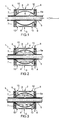
- Figure 1 shows a die of the present invention as a whole, with the reference number 1.
- the die 1 comprises an upper shell 2 and a lower shell 3, which can be coupled in order to form a molding cavity 4, wherein a portion of a tube 5 is fluid-tightly housed in order to manufacture the cuff.
- Each shell 2 and 3 comprises an external box structure 6 and an inner wall 7, having a semi-ovoid shape and closing the external box structure 6.
- the internal wall 7 delimits the half of the molding cavity 4.
- a hollow space 8 In the external box structure it is formed a first plurality of canalizations 9 connecting the molding cavity 4 to the outside, and a second plurality of canalizations 10 connecting the hollow space 8 to the outside.
- a hot liquid is injected through canalizations 9 into the molding cavity 4, which houses the portion of tube 5 to be molded.
- the hot liquid comes therefore in contact with a portion of the sheath of the tube 5 for softening it in order to be able to model it.
- the sheath 5a does not adhere to the underlying tube because of the air between the contact surfaces, as will be described subsequently.
- the hot liquid is extracted through the same canalizations 9 ( figure 3 ) by means of a light vacuum. During the extraction of the hot liquid, the portion of softened sheath 5a is suctioned towards the internal wall 7, shaping itself on it.
- the cold liquid is extracted through canalizations 10 ( figure 5 ), and the die is opened ( figure 6 ) for extracting the tube 5 whereon the cuff 11 is formed.
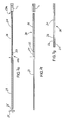
- a tracheal tube, extruded and successively cut at the desired length, is indicated with 21.
- a superficial incision 22 has been cut out on the tracheal tube 21 to connect an inflation lumen (already known and not illustrated for the sake of simplicity) to the outside in relation to the cuff to be provided as described hereinafter.
- Figure 7b shows a metal core 23 around which the tracheal tube 21 is placed to form an assembly 24.
- the metal core 23 is hollow and comprises a connecting end 23a to be connected to a feeding line for compressed air L, and a truncated conical end 23b having some holes (not shown) for the outlet of the compressed air.
- the second end 23b having a truncated conical shape remains outside the tracheal tube 21.
- Figure 7c shows a second assembly 25 comprising an extruded and cooled sheath 26 inserted inside a metal tube 27.
- the position of the sheath 26 in the tube 27 is kept fixed by means of a clamp 28.
- the metal tube 27 has an inner diameter larger than the diameter of the sheath 26, so that said sheath 26, once inflated, can take on the size of the metal tube 27.
- the assembly 25 is connected to the assembly 24 by bringing the truncated conical end 23b inside a first end of the sheath 26.
- the air injection through the truncated conical end 23b starts in this position, while at the same time the assembly 24 slides inside the assembly 25 obtaining a new assembly 29.
- the outcoming air inflates the sheath 26 and keeps it adherent to the metal tube 27 by simultaneously forming an air cushion around the tracheal tube 21.
- the thus formed air cushion allows the tracheal tube 21 to slide into the sheath 26, which, having an inner diameter smaller than the outer diameter of the tube and being made of an elastic material, stays adherent to the tracheal tube 21 as soon as the air cushion collapses.
- Figure 7e shows the splitting up of the assembly 29 once the sheath 26 has completely adhered to the tracheal tube 21.
- the splitting up occurs by releasing the clamp 28 and extracting from the metal tube 27 the tracheal tube 21 and the sheath 26 surrounding it. Once extracted, the portion of sheath 26 is cut in relation to the truncated conical end 23b, while inside the metal tube 27 a new portion of sheath 26 is placed for a new production cycle.
- Figure 7f shows the detachment of the metal core 23 from the tracheal tube 21, while the sheath 26 undergoes a finishing cut for adapting it to the size of the tracheal tube 21, thus obtaining the semifinished product of medical tube 30.
- Figure 7g shows the semifinished product 30 whereon an incision 31 is cut out for connecting in use the inflation lumen with a portion of the inflation tube it will be glued onto.
- the semifinished product 30 is suitable for insertion into the die 1 of the present invention.
- Figure 8a shows a continuously extruded tracheal tube 41, cooled with air and on which a superficial incision 42 is cut out at a predefined distance for connecting the inflation lumen (already known and not shown for the sake of simplicity) to the cuff to be provided as described hereinafter.
- the tracheal tube 41 has such a stiffness that it does not need a metal core as was needed in the embodiments of figure 7 .
- Figure 8b shows a covering step of the tracheal tube 41 with a sheath 43.
- the tracheal tube 41 is continuously inserted in a second extrusion head 44 by means of which the covering sheath 43 is produced by overextrusion.
- plastic material enters the extrusion head 44 through an inlet 44b and is overextruded around tube 41 forming the said sheath 43.
- some air is injected at regular intervals between the tracheal tube 41 and the forming sheath 43.
- the air enters the extrusion head 44 through an inlet 44a, in use connected to a feeding line of compressed air, and is injected in relation to the superficial incisions 42 between the sheath 43 and the tracheal tube 41 so that some non-adhesion areas are formed around said incisions 42.
- a semifinished medical tube 45 comprising a regularly distributed plurality of swellings 46 of the sheath 43 in the areas around the incisions 42.
- regularly distributed incisions 47 are cut out for connecting in use the inflation lumen to respective portions of the inflation tube they will be glued onto.
- the die of the present invention is particularly simple, both in its manufacture and in its use.
- the die of the present invention can be advantageously used in plastic tubes which have been covered with a sheath having antimicrobial activity.
Landscapes
- Health & Medical Sciences (AREA)
- Engineering & Computer Science (AREA)
- Manufacturing & Machinery (AREA)
- Life Sciences & Earth Sciences (AREA)
- Mechanical Engineering (AREA)
- Heart & Thoracic Surgery (AREA)
- Biomedical Technology (AREA)
- Veterinary Medicine (AREA)
- Pulmonology (AREA)
- Anesthesiology (AREA)
- Child & Adolescent Psychology (AREA)
- Hematology (AREA)
- Animal Behavior & Ethology (AREA)
- General Health & Medical Sciences (AREA)
- Public Health (AREA)
- Biophysics (AREA)
- Media Introduction/Drainage Providing Device (AREA)
- Extrusion Moulding Of Plastics Or The Like (AREA)
- Materials For Medical Uses (AREA)
- Moulds For Moulding Plastics Or The Like (AREA)
- Shaping Of Tube Ends By Bending Or Straightening (AREA)
- Moulding By Coating Moulds (AREA)
- Blow-Moulding Or Thermoforming Of Plastics Or The Like (AREA)
Abstract
Description
- The present invention concerns a die for molding a cuff on a plastic tube.
- In particular the die object of the present invention is advantageously, but not exclusively, used for molding a cuff on a tracheal tubes or a tracheostomy cannula.
- Here and hereinafter the term "cuff" is intended to mean an inflatable balloon attached around a tube, e.g. a tracheal tube. In tracheal tubes the purpose of the cuff is to function as a seal between tube and trachea, in order to prevent air from getting out and bacteria to enter the lungs. In other catheters, e.g. urine catheters, the purpose of the cuff is to block and secure the tube in the body part where it is inserted into.
- Tracheal tubes are used as means of conveying air or gas mixtures delivered by an Intensive Care Unit or Anaesthesia ventilator, through a breathing circuit, into the patient airways. Tracheostomy cannulas can have the same use as tracheal tubes or can be installed on spontaneously breathing patients who for a particular disease or accidental reasons cannot breath autonomously and sufficiently without this airway bypass.
- Usually, the cuff is obtained through a blowing process or an alternative technology of pre-extruded tubing expansion. The assembly process of the cuff on the tube consists of the following phases:
- cutting of the cuff ends, named collars;
- insertion of the so obtained cuff on the tube and correcting its positioning;
- gluing with solvents or adhesive.
- The result obtained from the above process is the formation of a kind of step next to the collar cutting edge. This step represents a traumatic factor during intubation operation because of the possible abrasions it can cause. This problem is particularly relevant for children and infant patients where the diameter of the tubes is narrower and the collar thickness is crucial.
- Another problem of the prior art process relates to a manufacturing issue. In fact, the shaping and the assembly operations render the whole process slow, expensive and relying heavily on personnel experience and ability. It is important to notice that such problems become more relevant when the tube has a narrow diameter (e.g. for children and infant patients) and when the cuffs are made of polyurethane (PU) with reduced thickness and easy to damaged during handling, tubing and gluing.
- Another way to obtain a cuff on tubes is disclosed on
EP1733752 . This method provides the production of silicon catheters comprising the adding of a antibonding agent in the zone of the cuff shaping. As it can be easily understood, the adding of a antibonding agent could entail time wasting and high cost problems. - The aim of the present invention is to achieve a die for molding cuffs on plastic tubes whose technical characteristics are such to obtain said molding in a simple and effective way.
- The object of the present invention is to achieve a die for molding cuffs on plastic tubes whose essential characteristics are reported in
claim 1 and 8, and whose preferred and/or auxiliaries characteristics are reported inclaims 2 to 7 and 9 to 19. - For a better understanding of the present invention, a preferred embodiment is described, in an illustrative and not limitative way, with a reference to the accompany drawings in which
-
figures 1-6 show the die of the present invention during six different manufacturing steps; -
figures 7a-7g show the manufacture of a tube for use with the die of the present invention and -
figures 8a-8b show an alternative method of manufacture of the tube for use with the die of the present invention. -
Figure 1 shows a die of the present invention as a whole, with the reference number 1. - The die 1 comprises an
upper shell 2 and alower shell 3, which can be coupled in order to form amolding cavity 4, wherein a portion of atube 5 is fluid-tightly housed in order to manufacture the cuff. - Each
shell external box structure 6 and aninner wall 7, having a semi-ovoid shape and closing theexternal box structure 6. Theinternal wall 7 delimits the half of themolding cavity 4. Between theexternal box structure 6 and theinternal wall 7 is then defined ahollow space 8. In the external box structure it is formed a first plurality ofcanalizations 9 connecting themolding cavity 4 to the outside, and a second plurality ofcanalizations 10 connecting thehollow space 8 to the outside. - Referring now to
figures 2-6 , it is described hereinafter the use of the die of the present invention. - As shown in
figure 2 , a hot liquid is injected throughcanalizations 9 into themolding cavity 4, which houses the portion oftube 5 to be molded. The hot liquid comes therefore in contact with a portion of the sheath of thetube 5 for softening it in order to be able to model it. In particular, thesheath 5a does not adhere to the underlying tube because of the air between the contact surfaces, as will be described subsequently. - Once a pre-determined period of time, sufficient for the softening the
sheath 5a, has elapsed, the hot liquid is extracted through the same canalizations 9 (figure 3 ) by means of a light vacuum. During the extraction of the hot liquid, the portion of softenedsheath 5a is suctioned towards theinternal wall 7, shaping itself on it. - Now, a cold liquid is inserted into the
hollow space 8 through canalizations 10 (figure 4 ). The cooling due to the cold liquid on theinternal wall 7 stiffens the portion ofsheath 5a, thus letting it take its final shape. - Once the portion of
sheath 5a has taken its final shape, the cold liquid is extracted through canalizations 10 (figure 5 ), and the die is opened (figure 6 ) for extracting thetube 5 whereon thecuff 11 is formed. - For providing a more complete understanding of the present invention, the manufacture of a tracheal tube for use with the die of the present invention will now be described.
- In
figure 7a a tracheal tube, extruded and successively cut at the desired length, is indicated with 21. Asuperficial incision 22 has been cut out on thetracheal tube 21 to connect an inflation lumen (already known and not illustrated for the sake of simplicity) to the outside in relation to the cuff to be provided as described hereinafter. -
Figure 7b shows ametal core 23 around which thetracheal tube 21 is placed to form anassembly 24. In particular, themetal core 23 is hollow and comprises a connectingend 23a to be connected to a feeding line for compressed air L, and a truncated conical end 23b having some holes (not shown) for the outlet of the compressed air. As shown, the second end 23b having a truncated conical shape remains outside thetracheal tube 21. -
Figure 7c shows asecond assembly 25 comprising an extruded and cooledsheath 26 inserted inside ametal tube 27. The position of thesheath 26 in thetube 27 is kept fixed by means of aclamp 28. In particular, themetal tube 27 has an inner diameter larger than the diameter of thesheath 26, so that saidsheath 26, once inflated, can take on the size of themetal tube 27. - As shown in
figure 7d , theassembly 25 is connected to theassembly 24 by bringing the truncated conical end 23b inside a first end of thesheath 26. The air injection through the truncated conical end 23b starts in this position, while at the same time theassembly 24 slides inside theassembly 25 obtaining anew assembly 29. During the sliding of theassembly 24 inside theassembly 25 the outcoming air inflates thesheath 26 and keeps it adherent to themetal tube 27 by simultaneously forming an air cushion around thetracheal tube 21. The thus formed air cushion allows thetracheal tube 21 to slide into thesheath 26, which, having an inner diameter smaller than the outer diameter of the tube and being made of an elastic material, stays adherent to thetracheal tube 21 as soon as the air cushion collapses. -
Figure 7e shows the splitting up of theassembly 29 once thesheath 26 has completely adhered to thetracheal tube 21. The splitting up occurs by releasing theclamp 28 and extracting from themetal tube 27 thetracheal tube 21 and thesheath 26 surrounding it. Once extracted, the portion ofsheath 26 is cut in relation to the truncated conical end 23b, while inside the metal tube 27 a new portion ofsheath 26 is placed for a new production cycle. -
Figure 7f shows the detachment of themetal core 23 from thetracheal tube 21, while thesheath 26 undergoes a finishing cut for adapting it to the size of thetracheal tube 21, thus obtaining the semifinished product ofmedical tube 30. -
Figure 7g shows thesemifinished product 30 whereon an incision 31 is cut out for connecting in use the inflation lumen with a portion of the inflation tube it will be glued onto. Thesemifinished product 30 is suitable for insertion into the die 1 of the present invention. - With a reference to
figures 8a-8b , a second method for the manufacture of a tracheal tube is shown, which differs from the one relating tofigures 7a-7g because of its larger automation. -
Figure 8a shows a continuously extrudedtracheal tube 41, cooled with air and on which asuperficial incision 42 is cut out at a predefined distance for connecting the inflation lumen (already known and not shown for the sake of simplicity) to the cuff to be provided as described hereinafter. Thetracheal tube 41 has such a stiffness that it does not need a metal core as was needed in the embodiments offigure 7 . -
Figure 8b shows a covering step of thetracheal tube 41 with asheath 43. Once cooled and incised as previously described, thetracheal tube 41 is continuously inserted in asecond extrusion head 44 by means of which the coveringsheath 43 is produced by overextrusion. In particular, plastic material enters theextrusion head 44 through aninlet 44b and is overextruded aroundtube 41 forming the saidsheath 43. During the overextrusion of thesheath 43, some air is injected at regular intervals between thetracheal tube 41 and the formingsheath 43. In particular, the air enters theextrusion head 44 through an inlet 44a, in use connected to a feeding line of compressed air, and is injected in relation to thesuperficial incisions 42 between thesheath 43 and thetracheal tube 41 so that some non-adhesion areas are formed around saidincisions 42. It is thus obtained a semifinishedmedical tube 45 comprising a regularly distributed plurality ofswellings 46 of thesheath 43 in the areas around theincisions 42. Afterwards, regularly distributedincisions 47 are cut out for connecting in use the inflation lumen to respective portions of the inflation tube they will be glued onto. - As shown by the aforesaid description, the die of the present invention is particularly simple, both in its manufacture and in its use.
- In addition, the die of the present invention can be advantageously used in plastic tubes which have been covered with a sheath having antimicrobial activity.
Claims (14)
- Die (1) for molding a cuff on a plastic tube, the die comprising an upper shell (2) and a lower shell (3) defining a molding cavity (4) between the upper and lower shells for the insertion therein of said plastic tube; said die (1) being characterized in that each of said shells (2, 3) has an external wall structure (6) and an internal wall (7), the wall of a respective shell defining a half of said molding cavity (4) and the wall structure and the wall of each shell defining a hollow space (8) there between; said molding cavity (4) and said hollow spaces (8) being separated from each other by said internal walls (7); said die comprising openings (9, 10) which are connected with said molding cavity (4) and said hollow spaces (8) respectively.
- Die (1) according to Claim 1, characterized in that said molding cavity (4) and said hollow spaces (8) are able to be occupied by a fluid which is inserted and extracted through said openings (9, 10).
- Die (1) according to Claim 2, characterized in that said fluid is a liquid.
- Die (1) according to anyone of the preceding Claims, characterized in that said external structure has a box shape (6).
- Die (1) according to anyone of the preceding Claims, characterized in that the internal wall (7) has a semi-ovoid shape.
- Die (1) according to anyone of the preceding Claims, characterized in that said plastic tube is a medical tube.
- Die (1) according to Claim 6, characterized in that said medical tube is a tracheal tube or a tracheostomy cannula.
- Molding process for manufacturing a cuff on a plastic tube by means of a die according to any one of the preceding Claims; said process being characterized in that it comprises:- an insertion step, wherein a tube (5) is tightly housed in a molding cavity (4);- a softening step, wherein a portion of the sheath (5a) of the tube (5) is softened by using a fluid;- a molding step, wherein the portion of softened sheath (5a) adheres to internal walls (7); and- a stiffening step, wherein the portion of sheath (5a) adhering to the internal walls (7) is stiffened by using another fluid.
- Molding process according to Claim 8, characterized in that in said softening step a fluid is injected in said molding cavity (4) contacting and softening the sheath (5a).
- Molding process according to Claim 9, characterized in that said fluid is a hot liquid.
- Molding process according to Claim 10, characterized in that in said stiffening step another fluid in injected into a hollow space (8) of the die (1) stiffening the sheath adhering to the internal walls (3).
- Molding process according to Claim 11, characterized in that said another fluid is a cold liquid.
- Molding process according to any one of the Claims from 7 to 11, characterized in that said molding step is carried out by suctioning out the fluid used in said softening step.
- Molding process according to Claim 13, characterized in that in said molding step the fluid is suctioned out through openings (9) by means of a light vacuum.
Applications Claiming Priority (1)
| Application Number | Priority Date | Filing Date | Title |
|---|---|---|---|
| ITBO2009A000054A IT1398225B1 (en) | 2009-02-05 | 2009-02-05 | MOLD FOR THE FORMING OF A HEADPHONE ON A PLASTIC TUBE |
Publications (1)
| Publication Number | Publication Date |
|---|---|
| EP2216066A1 true EP2216066A1 (en) | 2010-08-11 |
Family
ID=41297746
Family Applications (1)
| Application Number | Title | Priority Date | Filing Date |
|---|---|---|---|
| EP09010544A Withdrawn EP2216066A1 (en) | 2009-02-05 | 2009-08-17 | Die for molding of a cuff on a plastic tube |
Country Status (4)
| Country | Link |
|---|---|
| US (1) | US8226881B2 (en) |
| EP (1) | EP2216066A1 (en) |
| JP (1) | JP2010179105A (en) |
| IT (1) | IT1398225B1 (en) |
Cited By (2)
| Publication number | Priority date | Publication date | Assignee | Title |
|---|---|---|---|---|
| WO2015162490A1 (en) * | 2014-04-25 | 2015-10-29 | Creative Balloons Maschinenbau Gmbh & Co. Kg | Device and method for cycle- and cost-optimized thermal transformation of hose blanks |
| AT518540A4 (en) * | 2016-05-24 | 2017-11-15 | Christian Lembacher Dr | Method for producing a ring-shaped endless tube (torus) |
Families Citing this family (2)
| Publication number | Priority date | Publication date | Assignee | Title |
|---|---|---|---|---|
| WO2017035836A1 (en) * | 2015-09-06 | 2017-03-09 | 黄俊荣 | Method for manufacturing endotracheal intubation tube and endotracheal intubation tube |
| CN119950970B (en) * | 2025-03-14 | 2025-11-11 | 宁波倍理医疗发展有限公司 | A double-layer balloon shaping mechanism |
Citations (3)
| Publication number | Priority date | Publication date | Assignee | Title |
|---|---|---|---|---|
| US5236659A (en) * | 1988-10-04 | 1993-08-17 | Cordis Corporation | Tailoring expansion properties of balloons for medical devices |
| EP1733752A1 (en) | 2005-06-17 | 2006-12-20 | Keun-Ho Lee | Apparatus and method for manufacturing balloon catheter |
| US20070088378A1 (en) * | 2005-10-14 | 2007-04-19 | Terumo Kabushiki Kaisha | Balloon forming method and balloon |
Family Cites Families (10)
| Publication number | Priority date | Publication date | Assignee | Title |
|---|---|---|---|---|
| US237168A (en) * | 1881-02-01 | carpenter | ||
| US2326041A (en) * | 1942-07-13 | 1943-08-03 | Lavallee Louis Joseph Aime | Plastic molding |
| US3454988A (en) * | 1966-08-29 | 1969-07-15 | Blazon Inc | Apparatus for molding hollow articles from a synthetic resin |
| US3704081A (en) * | 1971-01-21 | 1972-11-28 | Sinclair Koppers Co | Vacuum mold for making foamed polymeric articles |
| IT998837B (en) | 1972-11-09 | 1976-02-20 | Atoc Rubber Prod Inc | EQUIPMENT AND PROCEDURE FOR FORMING A FLEXIBLE DUCT |
| DE2711236C2 (en) | 1976-05-14 | 1982-09-23 | Shiro Osaka Ibaragi Kanao | Method and device for the continuous production of a pipe |
| AT376484B (en) | 1981-07-24 | 1984-11-26 | Kessler & Co Tech Chem Gmbh | TUBE WRAP HEAD WITH BENDABLE SHAFT |
| US5181505A (en) * | 1989-03-08 | 1993-01-26 | Lew Chel W | Method and apparatus for delivery of a medicament in the oral cavity |
| US5330345A (en) | 1992-07-16 | 1994-07-19 | Sheridan Catheter Corp. | Apparatus and method for continuously winding a length of material into a helical form |
| US8048093B2 (en) * | 2003-12-19 | 2011-11-01 | Boston Scientific Scimed, Inc. | Textured balloons |
-
2009
- 2009-02-05 IT ITBO2009A000054A patent/IT1398225B1/en active
- 2009-08-17 EP EP09010544A patent/EP2216066A1/en not_active Withdrawn
- 2009-09-10 US US12/556,826 patent/US8226881B2/en not_active Expired - Fee Related
-
2010
- 2010-02-05 JP JP2010024760A patent/JP2010179105A/en active Pending
Patent Citations (3)
| Publication number | Priority date | Publication date | Assignee | Title |
|---|---|---|---|---|
| US5236659A (en) * | 1988-10-04 | 1993-08-17 | Cordis Corporation | Tailoring expansion properties of balloons for medical devices |
| EP1733752A1 (en) | 2005-06-17 | 2006-12-20 | Keun-Ho Lee | Apparatus and method for manufacturing balloon catheter |
| US20070088378A1 (en) * | 2005-10-14 | 2007-04-19 | Terumo Kabushiki Kaisha | Balloon forming method and balloon |
Cited By (4)
| Publication number | Priority date | Publication date | Assignee | Title |
|---|---|---|---|---|
| WO2015162490A1 (en) * | 2014-04-25 | 2015-10-29 | Creative Balloons Maschinenbau Gmbh & Co. Kg | Device and method for cycle- and cost-optimized thermal transformation of hose blanks |
| US10456953B2 (en) | 2014-04-25 | 2019-10-29 | Creative Balloons Gmbh | Device and method for cycle- and cost-optimized thermal transformation of hose blanks |
| AT518540A4 (en) * | 2016-05-24 | 2017-11-15 | Christian Lembacher Dr | Method for producing a ring-shaped endless tube (torus) |
| AT518540B1 (en) * | 2016-05-24 | 2017-11-15 | Christian Lembacher Dr | Method for producing a ring-shaped endless tube (torus) |
Also Published As
| Publication number | Publication date |
|---|---|
| ITBO20090054A1 (en) | 2010-08-06 |
| US20100194001A1 (en) | 2010-08-05 |
| US8226881B2 (en) | 2012-07-24 |
| JP2010179105A (en) | 2010-08-19 |
| IT1398225B1 (en) | 2013-02-22 |
Similar Documents
| Publication | Publication Date | Title |
|---|---|---|
| US20120180791A1 (en) | Ventilator Attachment Fitting Usable on an Endotracheal Tube Having an Integrally Formed Suction Lumen and Method of Making And/Or Using the Same | |
| US20100147309A1 (en) | Tracheal Catheter With a Flexible Lumen for Subglottic Suctioning | |
| US8535265B2 (en) | Tracheal catheter with suction lumen port in close proximity to the cuff | |
| EP2754461B1 (en) | Suction catheter device | |
| US20040144387A1 (en) | Double-balloon endobronchial catheter for one lung isolation anesthesia and surgery | |
| EP2216066A1 (en) | Die for molding of a cuff on a plastic tube | |
| KR20070006829A (en) | Airway device for laryngeal therapy | |
| JPS59120167A (en) | Endotracheal tube apparatus | |
| WO2007149204A1 (en) | Thin cuff for use with medical tubing and method and apparatus for making the same | |
| US8439041B2 (en) | Tracheal tube with scaffolding-supported wall | |
| EP2194916B1 (en) | A tubular workpiece for producing an improved balloon cuff tracheostomy tube, and method | |
| EP2216065B1 (en) | Method for manufacturing a cuff on a plastic tube provided with an external sheath | |
| JP5986743B2 (en) | Method for manufacturing inner suction port of tracheal tube with cuff | |
| CN111346285A (en) | Improved single-cavity bronchial catheter | |
| WO2015150721A1 (en) | Medico-surgical tubes, cuffs and their manufacture | |
| CN210078522U (en) | Formula of can letting out trachea shutoff type trachea cannula | |
| US10518051B2 (en) | Closed automated suction device and method | |
| CN211962767U (en) | A double lumen bronchial catheter | |
| WO2022099103A1 (en) | Endotracheal tube | |
| CN112316266B (en) | Auxiliary expansion sleeve for transnasal intubation | |
| CN216496904U (en) | Artificial airway replacement catheter | |
| CN214679621U (en) | Trachea cannula for assisting in removing sputum scab by air bag | |
| US20250001111A1 (en) | Multi-cuffed endotracheal tubes | |
| JP2016077509A (en) | Tracheal tube | |
| CN208693970U (en) | The fixed throat cover air flue conduit pipe in multi-cavity road |
Legal Events
| Date | Code | Title | Description |
|---|---|---|---|
| PUAI | Public reference made under article 153(3) epc to a published international application that has entered the european phase |
Free format text: ORIGINAL CODE: 0009012 |
|
| AK | Designated contracting states |
Kind code of ref document: A1 Designated state(s): AT BE BG CH CY CZ DE DK EE ES FI FR GB GR HR HU IE IS IT LI LT LU LV MC MK MT NL NO PL PT RO SE SI SK SM TR |
|
| AX | Request for extension of the european patent |
Extension state: AL BA RS |
|
| 17P | Request for examination filed |
Effective date: 20101216 |
|
| 17Q | First examination report despatched |
Effective date: 20130326 |
|
| RIC1 | Information provided on ipc code assigned before grant |
Ipc: A61M 25/00 20060101ALI20171018BHEP Ipc: B29C 49/48 20060101ALI20171018BHEP Ipc: A61M 25/10 20130101AFI20171018BHEP |
|
| GRAP | Despatch of communication of intention to grant a patent |
Free format text: ORIGINAL CODE: EPIDOSNIGR1 |
|
| INTG | Intention to grant announced |
Effective date: 20171127 |
|
| STAA | Information on the status of an ep patent application or granted ep patent |
Free format text: STATUS: THE APPLICATION IS DEEMED TO BE WITHDRAWN |
|
| 18D | Application deemed to be withdrawn |
Effective date: 20180410 |