EP2215819B1 - Dynamische strombegrenzungen - Google Patents
Dynamische strombegrenzungen Download PDFInfo
- Publication number
- EP2215819B1 EP2215819B1 EP08847894.6A EP08847894A EP2215819B1 EP 2215819 B1 EP2215819 B1 EP 2215819B1 EP 08847894 A EP08847894 A EP 08847894A EP 2215819 B1 EP2215819 B1 EP 2215819B1
- Authority
- EP
- European Patent Office
- Prior art keywords
- power
- current
- event
- provision
- network
- Prior art date
- Legal status (The legal status is an assumption and is not a legal conclusion. Google has not performed a legal analysis and makes no representation as to the accuracy of the status listed.)
- Not-in-force
Links
Images


Classifications
-
- H—ELECTRICITY
- H02—GENERATION; CONVERSION OR DISTRIBUTION OF ELECTRIC POWER
- H02J—CIRCUIT ARRANGEMENTS OR SYSTEMS FOR SUPPLYING OR DISTRIBUTING ELECTRIC POWER; SYSTEMS FOR STORING ELECTRIC ENERGY
- H02J1/00—Circuit arrangements for DC mains or DC distribution networks
- H02J1/14—Balancing the load in a network
-
- H—ELECTRICITY
- H04—ELECTRIC COMMUNICATION TECHNIQUE
- H04L—TRANSMISSION OF DIGITAL INFORMATION, e.g. TELEGRAPHIC COMMUNICATION
- H04L12/00—Data switching networks
- H04L12/02—Details
- H04L12/10—Current supply arrangements
-
- H—ELECTRICITY
- H02—GENERATION; CONVERSION OR DISTRIBUTION OF ELECTRIC POWER
- H02J—CIRCUIT ARRANGEMENTS OR SYSTEMS FOR SUPPLYING OR DISTRIBUTING ELECTRIC POWER; SYSTEMS FOR STORING ELECTRIC ENERGY
- H02J1/00—Circuit arrangements for DC mains or DC distribution networks
- H02J1/04—Constant-current supply systems
Definitions
- the present disclosure relates generally to power provisioning, and more particularly to providing power to network devices.
- PoE Power over Ethernet
- PSE Power Sourcing Equipment
- Each PD is often allocated the maximum power allowed by the specification (approximately 12.95 Watts, drawing up to 350 mA of current over a twisted pair connection at between 44 and 57 Volts - note that the cable introduces some power dissipation due to resistance, so the amount of power supplied by the PSE is about 15.4 W at 44 V).
- a PSE having a 154 W power supply is able to power 10 PDs allocated 12.95 W each.
- each port can provide 720 mA of continuous current, permitting excursions of up to approximately 15% more current.
- most PoE+ implementations thus far have limited the per-port current to less than 820 mA.
- Some pre-standard PoE + implementations are configurable to have varying current limits because the PoE + standard has not yet been completed.
- some such implementations allow the current limit to be changed to comply with the specification once finalized (by a flash hardware update or reprogramming).
- FR-A-2823027 describes installation for managing power supplied to aircraft passengers.
- US-A-2005/0078024 describes a digital current limiter that is capable of monitoring and controlling multiple current flows concurrently.
- Various embodiments are provided for allocating and providing power to network devices, while ensuring that a power supply is not overburdened by current increases due to voltage spikes.
- One embodiment is a method for allocating and providing power to a network device.
- the method includes (i) receiving an electronic request to power a network device with a requested amount of power, (ii) establishing a worst-case current draw of the device in the event of a pre-defined maximum voltage slew rate, and (iii) selectively (a) allocating and providing power to the device when a remaining power capacity is greater than or equal to a provision voltage multiplied by the worst-case current draw of the device in the event of the maximum voltage slew rate, and (b) denying power to the device when the remaining power capacity is less than the provision voltage multiplied by the worst-case current draw of the device in the event of the maximum voltage slew rate.
- the apparatus includes a network interface, a power supply, and a controller coupled to the network interface.
- the power supply includes a capacitor having a capacitance.
- the controller is coupled to the network interface.
- the controller is configured to (a) send a request to power sourcing equipment, over the network interface, to be provided a particular amount of power over the network interface, the power to be provided to the local power supply, and (b) report, over the network interface, the capacitance to the power sourcing equipment.
- the apparatus includes a power supply, a network interface, and a controller.
- the power supply has a provision voltage and a remaining power capacity.
- the controller is coupled to the network interface.
- the controller is configured to (i) receive, over the network interface, a request to power a device over the network interface with a requested amount of power, (ii) establish a worst-case current draw of the device in the event of a pre-defined maximum voltage slew rate, and (iii) selectively (a) allocate and provide power to the device from the power supply over the network interface when the remaining power capacity is greater than or equal to the provision voltage multiplied by the worst-case current draw of the device in the event of the maximum voltage slew rate, and (b) deny power to the device when the remaining power capacity is less than the provision voltage multiplied by the worst-case current draw of the device in the event of the maximum voltage slew rate.
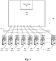
- a common application of PoE is voice over IP (VOIP) telephony.
- VOIP voice over IP
- Most VOIP telephones use less than 6 W of power.
- a VOIP phone might require 100 mA of current for 4.88 W of power (5.01 W at the PSE due to power losses over the cable).
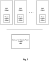
- a 240 W power supply 32 is enough to provide power to 48 such VOIP phones 34, each connected to PSE 36 over network cables 38.
- a voltage spike 1 affects the power supply 32 at the PSE 36
- the current drawn by the VOIP phones 34 can momentarily increase and overload the system 30.
- each phone 34 is drawing 100 mA of current and each phone has a IEEE 802.3 standard 180 micro-Farad capacitor 40 in its internal power supply 42
- a voltage spike having a slew rate of 83.3 V/s is sufficient to cause each PD 34 to draw additional current from the PSE 36 bringing the total power requirement of the system 30 to 15% above the stated 240 W power capacity of the PSE power supply 32.
- the PSE 36 only allocates as much power as could be drawn if every PD 34 drew extra current due to a largest-anticipated voltage slew rate.
- voltage spikes having slew rates greater than 200 V/s are highly improbable, while in other systems voltage spikes with slew rates up to 950 V/s are possible.
- each PD 34 could momentarily draw 136 mA of current in the event of a largest-anticipated voltage spike of 200 V/s.
- 50 V x 136 mA 6.8 W of power must be allocated to each PD 34, allowing only 40 such VOIP phones 34 to be powered by 240 W power supply 32 (with temporary capacity to supply 276 W).
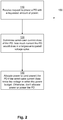
- Fig. 2 depicts a method 100 that may be practiced in accordance with one embodiment to prevent a voltage spike from harming the system 30.
- PSE 36 receives, over network cable 38, a request to power a particular PD 34 with a requested amount of power.
- the PSE 36 In order to determine if the power supply 32 has sufficient power to power the PD 34, the PSE 36 must determine exactly how much current the PD 34 could draw in the event of a largest-anticipated voltage spike (step 120). This may be done by multiplying the capacitance of capacitor 40 by the largest-anticipated voltage slew rate (e.g., 200 V/s) and adding that amount to the requested amount of power divided by the provision voltage to calculate a worst-case current draw of the PD 34. The largest-anticipated voltage slew rate is pre-programmed into the PSE 36, and its value represents the best reasonable guess of engineers as to the maximum voltage slew rate possible (or likely) in the device. In one embodiment, the PSE 36 assumes an IEEE standard 180 micro-Farads of capacitance. In another embodiment, the PD 34 reports the capacitance of its capacitor 40 to the PSE 36 for use in the above calculation.
- the largest-anticipated voltage slew rate e.g. 200 V/
- the PSE 36 keeps track of a remaining power budget. If the worst-case current draw of the PD 34 times the provision voltage (e.g., 50 V) falls within the remaining power budget, then the PSE 36 allocates an amount of power equal to the worst-case current draw of the PD 34 times the provision voltage to the PD 34 and subtracts that amount from the remaining power budget to derive a new remaining power budget. Power can then be provided to the PD 34 as requested. However, if there is not enough power remaining in the power budget to power the device under a worst-case current draw, then no power is allocated or provided to the requesting PD 34 (step 130).
- the provision voltage e.g. 50 V
- the maximum current allowed over each port is limited to allow additional devices to be powered.
- a PD 34 having a 100 mA current requirement can occasionally require a burst of 115% power.
- the PD could in some circumstances require 15% additional current, or 115 mA.
- power supplies 32 sometimes have a margin of error in the amount of current they actually provide.
- a provision tolerance of the power supply e.g., 8.7% may be added to that amount.
- some PSEs faced with a demand for 115 mA could supply an additional 10 mA. This amount would need to be able to pass over the cable 38.
- each PD 34 could require 125 mA, so a current limit of 125 mA could safely be imposed on the cable 38 without under-powering the PD 34.
- the 240 W power supply would be able to support more PDs 34.
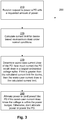
- Fig. 3 depicts a method 200 that may be practiced in accordance with this embodiment to prevent a voltage spike from harming the system 30.
- PSE 36 receives, over network cable 38, a request to power a particular PD 34 with a requested amount of power.
- a per-port current limit is calculated for the device. (Calculating is defined to be “ascertaining by computation.” Calculation involves performing mathematical operations on one or more numerical inputs to produce one or more numerical outputs.)
- the per-port current limit for the device is calculated by multiplying the requested amount of power divided by the provision voltage by a burst factor (for example, a number in the range of 1.0 to 1.15, representing the ratio of actual instantaneous burst current draw to average current draw for a device) and adding a provision tolerance (for example, 8.7%, but in any event in the range 0% to 20%, representing the accuracy of the power supply 32 circuitry in providing a specific amount of current).
- a burst factor for example, a number in the range of 1.0 to 1.15, representing the ratio of actual instantaneous burst current draw to average current draw for a device
- a provision tolerance for example, 8.7%, but in any event in the range 0% to 20%, representing the accuracy of the power supply 32 circuitry in providing a specific
- This calculated number should substantially be the per-port current limit, however, it may exceed this amount slightly, for example, by up to 5%.
- the per-port current limit may instead be established by the PD 34 reporting the maximum amount of current it is configured to be capable of drawing under normal operating conditions (i.e., no voltage spike) and adding the provision tolerance. In either event, if the PD 34 is eventually powered by the PSE 36, then this per-port current limit will be implemented over the cable 38, either by the PD 34 or by the PSE 36.
- the calculations of step 220 may be performed either by the PD 34 or by the PSE 36.
- the PSE 36 In order to determine if the power supply 32 has sufficient power to power the PD 34, the PSE 36 must determine exactly how much current the PD 34 could draw in the event of a largest-anticipated voltage slew rate (step 230). This may be done by multiplying the capacitance of capacitor 40 by the largest-anticipated voltage slew rate (e.g., 200 V/s) and adding that amount to the requested amount of power divided by the provision voltage to calculate a worst-case current draw of the PD 34. In one embodiment, the PSE 36 assumes an IEEE standard 180 micro-Farads of capacitance. In another embodiment, the PD 34 reports the capacitance of its capacitor 40 to the PSE 36 for use in the above calculation.
- a largest-anticipated voltage slew rate e.g. 200 V/s
- step 220 may be performed before step 230, or the two steps may be performed concurrently. In either event, the per-port current limit is actually implemented only once the device 34 has been powered (see step 240 below).
- the PSE 36 keeps track of a remaining power budget. If the worst-case current draw of the PD 34 times the provision voltage (e.g., 50 V) falls within the remaining power budget, then the PSE 36 allocates an amount of power equal to the worst-case current draw of the PD 34 times the provision voltage to the PD 34 and subtracts that amount from the remaining power budget to derive a new remaining power budget. Power can then be provided to the PD 34 as requested. However, if there is not enough power remaining in the power budget to power the device 34 under a worst-case current draw, then no power is allocated or provided to the requesting PD 34 (step 240).
- the provision voltage e.g. 50 V
- Fig. 4 depicts an example PD 34.
- the PD 34 has a power supply 42, which includes a capacitor 40 with capacitance C.
- the PD 34 also has a network interface 302 which connects to network cable 38 and to a controller 304. During operation, the network interface 302 provides power (which it receives across the cable 38) to the power supply 42.
- a current limiting device 306 interconnects the power supply 42 to the network interface 302.
- the power supply 42 couples to the network interface 302 without passing through a current limiting device 306.
- the current limiting device 306 is also connected to the controller 304 so that it can be controlled in the event that the current limit changes as the power needs of the PD change.
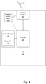
- Fig. 5 depicts an example PSE 36.
- the PSE 36 has a power supply 32 (which may be internal or external to the PSE 36).
- the PSE 36 also has a plurality of network interfaces 312 (only one of which is depicted) which connect to network cables 38. During operation, the network interface 312 receives power from the power supply 32 to send across the cable 38.
- the network interface 312 also couples to a controller 314.
- a current limiting device 316 (note that there may be a plurality of current limiting devices 316 - one connected to each network interface) interconnects the power supply 32 to the network interface 312.
- the power supply 32 couples to the network interface 312 without passing through a current limiting device 316.
- the current limiting device 316 is also connected to the controller 314 so that it can be controlled so that a port-specific current limit can be set.
- the controller 314 connects to memory 318.
- Memory 318 stores a power-allocation table 320 to keep track of the amount of power allocated to each PD 34.
- memory 318 also stores a current limit table 322 to keep track of the current limit assigned to each PD 34.
- the PSE 36 may connect to an uninterruptible power supply 330.
- the uninterruptible power supply 330 may include a plurality of redundant power supplies 332(a), 332(b), ... 332(n).
- the uninterruptible power supply 330 is configured to report a power capacity such that even if one of the power supplies 332 were to fail, the total capacity of the uninterruptible power supply 330 would still be at least the reported capacity.
- the power supplies 332 may typically be utilized in a load-sharing approach, but should one of them fail, the remaining power supplies would be capable of providing the total amount of allocated power.
- the uninterruptible power supply 330 may experience a temporary spike in voltage, thereby causing the capacitors 40 of the PDs 34 to draw more current.
- the multiple PSEs 436(a), 436(b), ... 436(n) may connect to a backup hot-standby power supply 438.
- the backup hot-standby power supply 438 is electronically switched in a controlled manner to power the PSE 436 with the failed power supply 432.
- the PSE 436 with the failed power supply 432 may experience a temporary spike in voltage, thereby causing the capacitors 40 of the PDs 34 to draw more current.
- embodiments have been provided for powering low-powered PDs without over-drawing a power supply even in the event of a large voltage spike.
- Embodiments have also been provided for supporting an increased number of PDs even while preventing over-drawing the power supply.
- the PDs 34 are VOIP telephones.
- the PDs 34 need not be VOIP telephones. They may be any sort of device that can receive power over a network, such as, for example, video cameras, motion detectors, etc.
- the power supply 32 may have any capacity, and is not limited to any particular capacity.
- the PSE 36 may have any number of powered ports, and is not limited to any particular number of powered ports.
- the PD 34 requests an amount of power to be provided by the PSE 36 (calculated by adding the amount of power the PD needs to the worst-case power loss across the cable 38 according to the standard).
- the PD 34 requests the amount of power that the PD 34 needs.
- any person having ordinary skill in the art would understand that some of the calculations would have to be modified to accommodate the different manner of reporting.
- determining exactly how much current the PD 34 could draw in the event of a largest-anticipated voltage spike would instead include multiplying the capacitance of capacitor 40 by the largest-anticipated voltage slew rate (e.g., 200 V/s) and adding that amount to the requested amount of power divided by the voltage received by the PD 34 (after the voltage has decreased due to the resistance of the cable 38) to calculate a worst-case current draw of the PD 34. Similar changes would be necessitated in steps 220 and 230 as well.
- the largest-anticipated voltage slew rate e.g. 200 V/s
Landscapes
- Engineering & Computer Science (AREA)
- Computer Networks & Wireless Communication (AREA)
- Signal Processing (AREA)
- Power Engineering (AREA)
- Small-Scale Networks (AREA)
- Direct Current Feeding And Distribution (AREA)
Claims (16)
- Verfahren (100), das in einer Netzwerkenergiegewinnungseinrichtung (36) ausgeführt wird, die eine Energieversorgung (32) mit einer festen Energiekapazität aufweist, wobei die Netzwerkenergiegewinnungseinrichtung eine Vielzahl von energieversorgten Netzwerkvorrichtungen (34) bei einer Versorgungsspannung mit Energie versorgt, wobei das Verfahren Folgendes umfasst:Empfangen einer elektronischen Anforderung bei der Netzwerkenergiegewinnungseinrichtung, eine Netzwerkvorrichtung der Vielzahl von energieversorgten Netzwerkvorrichtungen mit einer angeforderten Energiemenge (110) zu versorgen;Berechnen einer Stromaufnahme des ungünstigsten Falls der Netzwerkvorrichtung bei der Netzwerkenergiegewinnungseinrichtung im Fall einer vordefinierten maximalen Spannungsanstiegsrate (120);Zuweisen und Bereitstellen von Energie von der Energieversorgung zur Netzwerkvorrichtung, wenn eine Restenergiekapazität größer oder gleich der Versorgungsspannung multipliziert mit der Stromaufnahme des ungünstigsten Falls der Netzwerkvorrichtung im Fall der maximalen Spannungsanstiegsrate (130) ist; undVerweigern von Energie von der Energieversorgung zur der Netzwerkvorrichtung, wenn die Restenergiekapazität geringer als die Versorgungsspannung multipliziert mit der Stromaufnahme des ungünstigsten Falls der Vorrichtung im Fall der maximalen Spannungsanstiegsrate ist;wobei die Restenergiekapazität als die feste Energiekapazität der Netzwerkenergiegewinnungseinrichtung minus einer beliebigen Energie definiert ist, die bereits anderen energieversorgten Netzwerkvorrichtungen der Vielzahl von aktiven Netzwerkvorrichtungen zugewiesen wurde.
- Verfahren (100) nach Anspruch 1, wobei das Berechnen der Stromaufnahme des ungünstigsten Falls der Netzwerkvorrichtung (34) im Fall der vorbestimmten Maximalspannungsanstiegsrate das Summieren der folgenden Beträge umfasst:der angeforderten Energiemenge dividiert durch die Versorgungsspannung; undeine Kapazität eines Kondensators (40) innerhalb der Netzwerkvorrichtung multipliziert mit der maximalen Spannungsanstiegsrate.
- Verfahren (100) nach Anspruch 2, wobei die vorbestimmte maximale Spannungsanstiegsrate 200 Volt pro Sekunde beträgt.
- Verfahren (100) nach Anspruch 2, wobei die Kapazität des Kondensators (40) innerhalb der Netzwerkvorrichtung (34) als vorbestimmter Wert angenommen wird.
- Verfahren (100) nach Anspruch 2, wobei das Verfahren ferner Folgendes umfasst:
Empfangen eines Signals von der Netzwerkvorrichtung (34), das die Kapazität des Kondensators (40) in der Vorrichtung anzeigt. - Verfahren (100) nach Anspruch 1, wobei die angeforderte Energiemenge dividiert durch die Vorsorgungsspannung kleiner oder gleich 100 mA ist.
- Verfahren (100) nach Anspruch 6, wobei das Einrichten, dass die maximale Strommenge, die die Netzwerkvorrichtung (34) ziehen kann, falls die Versorgungsspannung im Wesentlichen konstant bleibt, die größte Strommenge ist, für die die Netzwerkvorrichtung konfiguriert ist, diese unter allen Umständen anzufordern, den Empfang eines Signals von der Netzwerkvorrichtung umfasst, das die größte Strommenge meldet, für die die Netzwerkvorrichtung konfiguriert ist, diese unter normalen Betriebsbedingungen zu ziehen.
- Verfahren (100) nach Anspruch 7, wobei der Prozentsatz im Wesentlichen 8,7 % beträgt.
- Verfahren (100) nach Anspruch 2, wobei die angeforderte Energiemenge dividiert durch die Versorgungsspannung kleiner ist als die Stromaufnahme des ungünstigsten Falls der Vorrichtung (34) im Fall der maximalen Spannungsanstiegsrate.
- Verfahren (100) nach Anspruch 1, wobei das Verfahren ferner Folgendes umfasst:Berechnen einer Stromgrenze für die Netzwerkvorrichtung (34), wobei das Berechnen der Stromgrenze für die Netzwerkvorrichtung Folgendes umfasst: Bestimmen einer maximalen Strommenge, die die Netzwerkvorrichtung ziehen kann, falls die Versorgungsspannung im Wesentlichen konstant bleibt, und Hinzufügen einer Versorgungstoleranz zu dieser maximalen Menge; undwesentliches Begrenzen der Gesamtstrommenge, die der Netzwerkvorrichtung bereitgestellt werden kann, auf die berechnete Stromgrenze für die Netzwerkvorrichtung; undwobei das Berechnen der Stromaufnahme des ungünstigsten Falls der Netzwerkvorrichtung für den Fall der maximalen Spannungsanstiegsrate Folgendes umfasst: Berechnen als Stromaufnahme des ungünstigsten Falls der Netzwerkvorrichtung für den Fall der maximalen Spannungsanstiegsrate eines Zahlenwertes, der kleiner oder gleich der berechneten Stromgrenze für die Netzwerkvorrichtung ist, optional wobei das Bestimmen der maximalen Strommenge, die die Netzwerkvorrichtung ziehen kann, falls die Versorgungsspannung im Wesentlichen konstant bleibt, Folgendes umfasst:Bestimmen, dass die maximale Strommenge, die die Netzwerkvorrichtung ziehen kann, falls die Versorgungsspannung im Wesentlichen konstant bleibt, die angeforderte Energiemenge dividiert durch die Versorgungsspannung multipliziert mit einem Verstärkungsfaktor ist, wobei der Verstärkungsfaktor eine Zahl im Bereich von 1,0 bis 1,15 ist, oder wobei das Bestimmen der maximalen Strommenge, die die Netzwerkvorrichtung ziehen kann, falls die Versorgungsspannung im Wesentlichen konstant bleibt, die größte Strommenge ist, für die die Netzwerkvorrichtung konfiguriert ist, diese unter allen Umständen anzufordern.
- Verfahren (100) nach Anspruch 10, wobei das Hinzufügen der Versorgungstoleranz zu der maximalen Menge Folgendes umfasst:
Hinzufügen der Versorgungstoleranz, wobei die Versorgungstoleranz gleich einem Prozentsatz der maximalen Strommenge ist, die die Netzwerkvorrichtung (34) ziehen kann, falls die Versorgungsspannung im Wesentlichen konstant bleibt, wobei der Prozentsatz im Bereich von 0 % bis 20 % liegt. - Vorrichtung (36), die Folgendes umfasst:eine Energieversorgung (32) mit einer festen Energiekapazität, wobei die Energieversorgung dafür konfiguriert ist, eine Vielzahl von mit Energie versorgten Netzwerkvorrichtungen (34) mit einer Versorgungsspannung und einer verbleibenden Energiekapazität mit Energie zu versorgen;eine Netzwerkschnittstelle (312); undeine Steuereinheit (314), die mit der Netzwerkschnittstelle verbunden ist, wobei die Steuereinheit für Folgendes konfiguriert ist:Empfangen einer Anforderung über die Netzwerkschnittstelle, eine Vorrichtung der Vielzahl von mit Energie versorgten Vorrichtungen über die Netzwerkschnittstelle mit einer angeforderten Energiemenge (110) zu versorgen;Berechnen einer Stromaufnahme des ungünstigsten Falls der Vorrichtung im Fall einer vorbestimmten maximalen Spannungsanstiegsrate (120);Zuweisen und Bereitstellen von Energie für die Vorrichtung von der Stromversorgung über die Netzwerkschnittstelle, wenn die Restenergiekapazität größer oder gleich der Versorgungsspannung multipliziert mit der Stromaufnahme des ungünstigsten Falls der Vorrichtung im Fall der maximalen Spannungsanstiegsrate (130) ist; undVerweigern der Energie für die Vorrichtung, wenn die Restenergiekapazität geringer als die Versorgungsspannung multipliziert mit der Stromaufnahme des ungünstigsten Falls der Vorrichtung im Fall der maximalen Spannungsanstiegsrate ist; wobei die Restenergiekapazität als die feste Energiekapazität der Energieversorgung minus einer beliebigen Energie definiert ist, die bereits anderen energieversorgten Netzwerkvorrichtungen der Vielzahl von aktiven Netzwerkvorrichtungen zugewiesen wurde.
- Vorrichtung (36) nach Anspruch 12, wobei die Steuereinheit (314) beim Berechnen der Stromaufnahme des ungünstigsten Falls der Netzwerkvorrichtung (34) im Fall der Maximalspannungsanstiegsrate folgende Beträge summieren kann:die angeforderte Energiemenge dividiert durch die Versorgungsspannung; undeine Kapazität eines Kondensators innerhalb der Vorrichtung multipliziert mit der maximalen Spannungsanstiegsrate, optional wobei die Steuereinheit ferner dafür konfiguriert ist, von der Vorrichtung über die Netzwerkschnittstelle ein Signal zu empfangen, das die Kapazität des Kondensators in der Vorrichtung anzeigt.
- Vorrichtung (36) nach Anspruch 12, wobei:die Steuereinheit (314) ferner für Folgendes konfiguriert ist:Berechnen einer Stromgrenze für die Vorrichtung (34), wobei das Berechnen der Stromgrenze für die Vorrichtung das Bestimmen einer maximalen Strommenge umfasst, die die Vorrichtung ziehen kann, falls die Versorgungsspannung im Wesentlichen konstant bleibt, und Hinzufügen einer Versorgungstoleranz zu dieser maximalen Menge; undwesentliches Begrenzen der Gesamtstrommenge, die der Vorrichtung bereitgestellt werden kann, auf die berechnete Stromgrenze für die Vorrichtung; unddie Steuereinheit beim Berechnen der Stromaufnahme des ungünstigsten Falls der Vorrichtung für den Fall der maximalen Spannungsanstiegsrate als die Stromaufnahme des ungünstigsten Falls der Vorrichtung im Falle der maximalen Spannungsanstiegsrate einen Zahlenwert berechnen kann, der optional kleiner oder gleich der berechneten Stromgrenze für die Vorrichtung ist, optional wobei die Steuereinheit bei der Bestimmung der maximalen Strommenge, die die Vorrichtung ziehen kann, falls die Spannung im Wesentlichen konstant bleibt, für Folgendes ausgelegt ist:Bestimmen, dass die maximale Strommenge, die die Vorrichtung ziehen kann, falls die Versorgungsspannung im Wesentlichen konstant bleibt, die angeforderte Energiemenge dividiert durch die Versorgungsspannung multipliziert mit einem Verstärkungsfaktor ist, wobei der Verstärkungsfaktor eine Zahl im Bereich von 1,0 bis 1,15 ist.
- Vorrichtung (36) nach Anspruch 12, wobei:die Energieversorgung (32) ist eine unterbrechungsfreie Energieversorgung mit einer ersten Energiequelle (332a) und einer zweiten Energiequelle (332b) ist; unddie vorbestimmte maximale Spannungsanstiegsrate gleich der größten Spannungsanstiegsrate der Stromversorgung ist, die durch einen Ausfall der ersten oder zweiten Energiequelle verursacht werden könnte.
- Vorrichtung (36) nach Anspruch 12, wobei die Vorrichtung ferner eine Strombegrenzungsvorrichtung (316) umfasst, wobei die Strombegrenzungsvorrichtung die Strommenge begrenzen kann, die von der Netzwerkvorrichtung (34) über die Netzwerkschnittstelle (312) zu der berechneten Stromgrenze für diese Vorrichtung gezogen werden kann.
Applications Claiming Priority (2)
| Application Number | Priority Date | Filing Date | Title |
|---|---|---|---|
| US11/937,254 US7902694B2 (en) | 2007-11-08 | 2007-11-08 | Dynamic current limits |
| PCT/US2008/082316 WO2009061711A1 (en) | 2007-11-08 | 2008-11-04 | Dynamic current limits |
Publications (3)
| Publication Number | Publication Date |
|---|---|
| EP2215819A1 EP2215819A1 (de) | 2010-08-11 |
| EP2215819A4 EP2215819A4 (de) | 2017-02-01 |
| EP2215819B1 true EP2215819B1 (de) | 2018-05-09 |
Family
ID=40623035
Family Applications (1)
| Application Number | Title | Priority Date | Filing Date |
|---|---|---|---|
| EP08847894.6A Not-in-force EP2215819B1 (de) | 2007-11-08 | 2008-11-04 | Dynamische strombegrenzungen |
Country Status (4)
| Country | Link |
|---|---|
| US (1) | US7902694B2 (de) |
| EP (1) | EP2215819B1 (de) |
| CN (1) | CN101855896B (de) |
| WO (1) | WO2009061711A1 (de) |
Families Citing this family (23)
| Publication number | Priority date | Publication date | Assignee | Title |
|---|---|---|---|---|
| US7902694B2 (en) * | 2007-11-08 | 2011-03-08 | Cisco Technology, Inc. | Dynamic current limits |
| US8106530B2 (en) | 2008-08-28 | 2012-01-31 | Cisco Technology, Inc. | Network-centric scheduled power provisioning method |
| US8627117B2 (en) * | 2009-06-26 | 2014-01-07 | Seagate Technology Llc | Device with power control feature involving backup power reservoir circuit |
| US9252874B2 (en) | 2010-10-13 | 2016-02-02 | Ccs Technology, Inc | Power management for remote antenna units in distributed antenna systems |
| US9160449B2 (en) | 2010-10-13 | 2015-10-13 | Ccs Technology, Inc. | Local power management for remote antenna units in distributed antenna systems |
| US11296504B2 (en) | 2010-11-24 | 2022-04-05 | Corning Optical Communications LLC | Power distribution module(s) capable of hot connection and/or disconnection for wireless communication systems, and related power units, components, and methods |
| EP2643947B1 (de) | 2010-11-24 | 2018-09-19 | Corning Optical Communications LLC | Stromverteilungsmodul(e) mit heissstart- und/oder stoppfunktion für verteilte antennensysteme und zugehörige aggregate, komponenten, und verfahren |
| US8656195B2 (en) | 2011-08-30 | 2014-02-18 | Hewlett-Packard Development Company, L.P. | Energy efficient ethernet control |
| US20130173946A1 (en) * | 2011-12-29 | 2013-07-04 | Efraim Rotem | Controlling power consumption through multiple power limits over multiple time intervals |
| US9154222B2 (en) | 2012-07-31 | 2015-10-06 | Corning Optical Communications LLC | Cooling system control in distributed antenna systems |
| US10257056B2 (en) | 2012-11-28 | 2019-04-09 | Corning Optical Communications LLC | Power management for distributed communication systems, and related components, systems, and methods |
| JP6226567B2 (ja) * | 2013-05-30 | 2017-11-08 | 株式会社日立アイイ−システム | 電動車両用バッテリ充電システム |
| WO2015029028A1 (en) | 2013-08-28 | 2015-03-05 | Corning Optical Communications Wireless Ltd. | Power management for distributed communication systems, and related components, systems, and methods |
| WO2015079435A1 (en) * | 2013-11-26 | 2015-06-04 | Corning Optical Communications Wireless Ltd. | Selective activation of communications services on power-up of a remote unit(s) in a distributed antenna system (das) based on power consumption |
| WO2016005256A1 (en) * | 2014-07-08 | 2016-01-14 | Koninklijke Philips N.V. | Powered device and power distribution system comprising the powered device |
| US9653861B2 (en) | 2014-09-17 | 2017-05-16 | Corning Optical Communications Wireless Ltd | Interconnection of hardware components |
| US9159829B1 (en) | 2014-10-07 | 2015-10-13 | Micron Technology, Inc. | Recessed transistors containing ferroelectric material |
| US10169104B2 (en) * | 2014-11-19 | 2019-01-01 | International Business Machines Corporation | Virtual computing power management |
| US9785175B2 (en) | 2015-03-27 | 2017-10-10 | Corning Optical Communications Wireless, Ltd. | Combining power from electrically isolated power paths for powering remote units in a distributed antenna system(s) (DASs) |
| TW201713106A (zh) * | 2015-09-24 | 2017-04-01 | 晶睿通訊股份有限公司 | 網路攝影機系統及其照明裝置 |
| US10505391B2 (en) * | 2017-04-28 | 2019-12-10 | Ciena Corporation | Power management for network device line modules |
| WO2020204727A1 (en) * | 2019-04-04 | 2020-10-08 | Hark Technologies As | A power adaption circuit |
| US20240201764A1 (en) * | 2022-12-19 | 2024-06-20 | Bks Tec Corp. | System for long-distance power transmission and method of operating the same |
Family Cites Families (53)
| Publication number | Priority date | Publication date | Assignee | Title |
|---|---|---|---|---|
| CA2326192A1 (en) * | 1998-04-02 | 1999-10-14 | Capstone Turbine Corporation | Power controller |
| US5995393A (en) * | 1998-07-31 | 1999-11-30 | Philips Electronics N.A. Corporation | Latching shutdown and delayed restart of DC power supply in broadband network |
| US6473608B1 (en) * | 1999-01-12 | 2002-10-29 | Powerdsine Ltd. | Structure cabling system |
| US7567579B2 (en) * | 1999-08-02 | 2009-07-28 | Microsemi Corp.-Analog Mixed Signal Group Ltd. | Multiple current limits for power over ethernet controller |
| FR2823027B1 (fr) | 2001-03-30 | 2003-07-25 | Labinal | Installation de gestion de puissance dans un avion |
| CA2442903C (en) * | 2002-09-26 | 2007-08-28 | R-Can Environmental Inc. | Fluid treatment system with uv sensor and intelligent driver |
| US7400062B2 (en) * | 2002-10-15 | 2008-07-15 | Microsemi Corp. - Analog Mixed Signal Group Ltd. | Rack level power management |
| US7026730B1 (en) * | 2002-12-20 | 2006-04-11 | Cisco Technology, Inc. | Integrated connector unit |
| US6817890B1 (en) * | 2003-05-06 | 2004-11-16 | Cisco Technology, Inc. | System and method for providing indicators within a connector assembly |
| US20050078024A1 (en) * | 2003-10-09 | 2005-04-14 | Honeywell International Inc. | Digital current limiter |
| US7356588B2 (en) * | 2003-12-16 | 2008-04-08 | Linear Technology Corporation | Circuits and methods for detecting the presence of a powered device in a powered network |
| US7209366B2 (en) * | 2004-03-19 | 2007-04-24 | Intel Corporation | Delivery regions for power, ground and I/O signal paths in an IC package |
| US7353407B2 (en) * | 2004-05-20 | 2008-04-01 | Cisco Technology, Inc. | Methods and apparatus for provisioning phantom power to remote devices |
| US7457252B2 (en) * | 2004-11-03 | 2008-11-25 | Cisco Technology, Inc. | Current imbalance compensation for magnetics in a wired data telecommunications network |
| US7363525B2 (en) * | 2004-10-07 | 2008-04-22 | Cisco Technology, Inc. | Bidirectional inline power port |
| US8300666B2 (en) * | 2004-10-07 | 2012-10-30 | Cisco Technology, Inc. | Inline power-based common mode communications in a wired data telecommunications network |
| US7620846B2 (en) * | 2004-10-07 | 2009-11-17 | Cisco Technology, Inc. | Redundant power and data over a wired data telecommunications network |
| US20060112285A1 (en) * | 2004-11-19 | 2006-05-25 | Linear Technology Corporation | Analog power management within power over ethernet system |
| US7373528B2 (en) * | 2004-11-24 | 2008-05-13 | Cisco Technology, Inc. | Increased power for power over Ethernet applications |
| US7478251B1 (en) * | 2004-12-23 | 2009-01-13 | Cisco Technology, Inc. | Methods and apparatus for provisioning uninterruptible power for power over Ethernet applications |
| US7472290B2 (en) * | 2004-12-23 | 2008-12-30 | Cisco Technology, Inc. | Methods and apparatus to maintain and utilize mobile power profile information |
| US7511515B2 (en) * | 2005-01-25 | 2009-03-31 | Linear Technology Corporation | System for providing power over communication cable having mechanism for determining resistance of communication cable |
| US7571331B2 (en) * | 2005-01-31 | 2009-08-04 | Microsemi Corp.—Analog Mixed Signal Group Ltd. | Means for preventing unintended powering of a first power over Ethernet controller |
| US20060218422A1 (en) * | 2005-03-28 | 2006-09-28 | Akros Silicon, Inc. | System and method to balance power signals from a network attached power sourcing device |
| US7368798B2 (en) * | 2005-03-28 | 2008-05-06 | Akros Silicon Inc. | Integrated DC/DC converter substrate connections |
| US7620825B2 (en) * | 2005-03-28 | 2009-11-17 | Akros Silicon Inc. | Systems and methods operable to allow loop powering of networked devices |
| US7761719B2 (en) * | 2005-03-28 | 2010-07-20 | Akros Silicon Inc. | Ethernet module |
| US7500118B2 (en) * | 2005-03-28 | 2009-03-03 | Akros Silicon Inc. | Network device with power potential rectifier |
| US7586840B2 (en) * | 2005-05-25 | 2009-09-08 | Cisco Technology, Inc. | Method and apparatus for detecting and fixing faults in an inline-power capable ethernet system |
| US8184525B2 (en) * | 2005-05-25 | 2012-05-22 | Cisco Technology, Inc. | Method and apparatus for detecting and fixing faults in an inline-power capable ethernet system |
| US7373532B2 (en) * | 2005-07-27 | 2008-05-13 | Cisco Technology, Inc. | Inline power controller |
| US7451329B2 (en) * | 2005-09-08 | 2008-11-11 | Cisco Technology, Inc. | Techniques for measuring network resistive loss within a power-sourcing apparatus |
| US7650519B1 (en) * | 2005-10-12 | 2010-01-19 | Teradici Corporation | Methods and apparatus for managing a user interface on a powered network |
| US7565555B2 (en) * | 2005-11-23 | 2009-07-21 | Cisco Technology, Inc. | Uninterruptible power supply resource sharing for multiple power sourcing equipment network devices |
| US7831844B2 (en) * | 2005-12-12 | 2010-11-09 | Linear Technology Corporation | Integrated powered device connector in system for supplying power over communication link |
| US8014412B2 (en) * | 2005-12-12 | 2011-09-06 | Linear Technology Corporation | Power sourcing equipment having bipolar junction transistor for controlling power supply and supporting AC disconnect-detection function |
| US7964993B2 (en) * | 2006-12-11 | 2011-06-21 | Akros Silicon Inc. | Network devices with solid state transformer and class AB output stage for active EMI suppression and termination of open-drain transmit drivers of a physical device |
| CN101371492B (zh) * | 2006-01-17 | 2012-08-15 | 美国博通公司 | 以太网供电控制器及对供电设备检测和分级的方法 |
| US7560825B2 (en) * | 2006-04-11 | 2009-07-14 | Akros Silicon, Inc. | Network devices for separating power and data signals |
| US7849333B2 (en) * | 2006-05-08 | 2010-12-07 | Cisco Technology, Inc. | Inline power allocation for power over Ethernet applications |
| US7647510B2 (en) * | 2006-06-22 | 2010-01-12 | Silicon Laboratories, Inc. | System and method of classification in power over ethernet systems |
| US7516340B2 (en) * | 2006-06-30 | 2009-04-07 | Silicon Laboratories, Inc. | Powered device including a classification signature resistor |
| US7715165B2 (en) * | 2006-07-11 | 2010-05-11 | Silicon Laboratories, Inc. | System and method of surge protection in a powered device |
| US20080037188A1 (en) * | 2006-08-11 | 2008-02-14 | A.C. Data Systems Of Idaho, Inc. | Surge suppression system for power over network cables |
| US8064179B2 (en) * | 2006-09-05 | 2011-11-22 | Silicon Laboratories Inc. | Integrated circuit including a switching regulator design for power over Ethernet devices |
| US20080104427A1 (en) * | 2006-10-27 | 2008-05-01 | Microsoft Corporation | Multi-stage power supply |
| US7706112B2 (en) * | 2006-12-19 | 2010-04-27 | Akros Silicon Inc. | Active clamp protection device |
| US7773354B2 (en) * | 2006-12-22 | 2010-08-10 | Silicon Laboratories, Inc. | Voltage protection circuit for power supply device and method therefor |
| US20080181316A1 (en) * | 2007-01-25 | 2008-07-31 | Philip John Crawley | Partitioned Signal and Power Transfer Across an Isolation Barrier |
| US7818591B2 (en) * | 2007-04-11 | 2010-10-19 | Cisco Technology, Inc. | Techniques for measuring network channel resistive loss between a power-sourcing apparatus and a powered device |
| US7865754B2 (en) * | 2007-08-24 | 2011-01-04 | Micrel, Inc. | Power budget management in power over ethernet systems |
| US8266456B2 (en) * | 2007-10-15 | 2012-09-11 | Apple Inc. | Supplying remaining available current to port in excess of bus standard limit |
| US7902694B2 (en) * | 2007-11-08 | 2011-03-08 | Cisco Technology, Inc. | Dynamic current limits |
-
2007
- 2007-11-08 US US11/937,254 patent/US7902694B2/en active Active
-
2008
- 2008-11-04 WO PCT/US2008/082316 patent/WO2009061711A1/en not_active Ceased
- 2008-11-04 CN CN2008801151586A patent/CN101855896B/zh not_active Expired - Fee Related
- 2008-11-04 EP EP08847894.6A patent/EP2215819B1/de not_active Not-in-force
Non-Patent Citations (1)
| Title |
|---|
| None * |
Also Published As
| Publication number | Publication date |
|---|---|
| US20090121548A1 (en) | 2009-05-14 |
| EP2215819A4 (de) | 2017-02-01 |
| WO2009061711A1 (en) | 2009-05-14 |
| CN101855896A (zh) | 2010-10-06 |
| US7902694B2 (en) | 2011-03-08 |
| CN101855896B (zh) | 2013-09-18 |
| EP2215819A1 (de) | 2010-08-11 |
Similar Documents
| Publication | Publication Date | Title |
|---|---|---|
| EP2215819B1 (de) | Dynamische strombegrenzungen | |
| US7511388B2 (en) | System and method of detection of power loss in powered ethernet devices | |
| US8656194B2 (en) | Method and system for distributing power to networked devices | |
| US20100106983A1 (en) | System and Method for Adjusting Information Handling System Over Current Protection | |
| EP1813057B1 (de) | Management der analogen leistung in einem power-over-ethernet-system | |
| US20090168278A1 (en) | Circuit device and method of supressing a power event | |
| US20100293398A1 (en) | System and Method for Preventing Disconnect of a Powered Device by a Power Source Equipment | |
| US9176556B2 (en) | Serial bus voltage compensation | |
| US6281602B1 (en) | Backup battery recharge controller for a telecommunications power system | |
| US11797070B2 (en) | Response mechanisms for power-interruption events in PoE systems | |
| US11063774B2 (en) | Virtualized chassis with power-over-ethernet for networking applications | |
| EP2950413B1 (de) | Telekommunikationsausrüstung, stromversorgungssystem und stromversorgungs-implementierungsverfahren | |
| CN108973760B (zh) | 一种基于物联网的充电桩管理方法 | |
| KR101932025B1 (ko) | PoE 스위칭 허브 장치 및 그 동작 방법 | |
| US20050157656A1 (en) | Low-impact method and apparatus for maintaining network access servers | |
| CN103190141B (zh) | 用户线路配电系统 | |
| US9939790B1 (en) | Variable rate rack installation | |
| US10461555B2 (en) | Battery charging for mobile devices | |
| US20170118031A1 (en) | Apparatus and method for supplying power | |
| US11630498B2 (en) | Powering method and powering system for Power over Ethernet | |
| US8904059B2 (en) | Method for controlling a data transfer on a serial transmission data transfer bus | |
| US6982860B2 (en) | Technique for fault isolation and transient load isolation for multiple electrical loads connected to a common electrical power source | |
| CN107196770B (zh) | 通过信号线进行供电的系统 | |
| US11334131B2 (en) | Power management in power adapters to deliver power to a power output coupled to an electronic device in accordance with power supply capability information | |
| US7076684B2 (en) | System and method for re-routing failed video calls |
Legal Events
| Date | Code | Title | Description |
|---|---|---|---|
| PUAI | Public reference made under article 153(3) epc to a published international application that has entered the european phase |
Free format text: ORIGINAL CODE: 0009012 |
|
| 17P | Request for examination filed |
Effective date: 20100225 |
|
| AK | Designated contracting states |
Kind code of ref document: A1 Designated state(s): AT BE BG CH CY CZ DE DK EE ES FI FR GB GR HR HU IE IS IT LI LT LU LV MC MT NL NO PL PT RO SE SI SK TR |
|
| AX | Request for extension of the european patent |
Extension state: AL BA MK RS |
|
| DAX | Request for extension of the european patent (deleted) | ||
| RIC1 | Information provided on ipc code assigned before grant |
Ipc: H02J 1/14 20060101ALN20160920BHEP Ipc: H04L 12/10 20060101ALI20160920BHEP Ipc: H04M 9/00 20060101AFI20160920BHEP |
|
| RA4 | Supplementary search report drawn up and despatched (corrected) |
Effective date: 20170105 |
|
| RIC1 | Information provided on ipc code assigned before grant |
Ipc: H04L 12/10 20060101ALI20161223BHEP Ipc: H02J 1/14 20060101ALN20161223BHEP Ipc: H04M 9/00 20060101AFI20161223BHEP |
|
| GRAP | Despatch of communication of intention to grant a patent |
Free format text: ORIGINAL CODE: EPIDOSNIGR1 |
|
| RIC1 | Information provided on ipc code assigned before grant |
Ipc: H04L 12/10 20060101ALI20171113BHEP Ipc: H02J 1/14 20060101ALN20171113BHEP Ipc: H04M 9/00 20060101AFI20171113BHEP |
|
| RIC1 | Information provided on ipc code assigned before grant |
Ipc: H04M 9/00 20060101AFI20171130BHEP Ipc: H04L 12/10 20060101ALI20171130BHEP Ipc: H02J 1/14 20060101ALN20171130BHEP |
|
| INTG | Intention to grant announced |
Effective date: 20171218 |
|
| GRAS | Grant fee paid |
Free format text: ORIGINAL CODE: EPIDOSNIGR3 |
|
| GRAA | (expected) grant |
Free format text: ORIGINAL CODE: 0009210 |
|
| AK | Designated contracting states |
Kind code of ref document: B1 Designated state(s): AT BE BG CH CY CZ DE DK EE ES FI FR GB GR HR HU IE IS IT LI LT LU LV MC MT NL NO PL PT RO SE SI SK TR |
|
| RAP1 | Party data changed (applicant data changed or rights of an application transferred) |
Owner name: CISCO TECHNOLOGY, INC. |
|
| REG | Reference to a national code |
Ref country code: GB Ref legal event code: FG4D |
|
| REG | Reference to a national code |
Ref country code: CH Ref legal event code: EP Ref country code: AT Ref legal event code: REF Ref document number: 998568 Country of ref document: AT Kind code of ref document: T Effective date: 20180515 |
|
| REG | Reference to a national code |
Ref country code: DE Ref legal event code: R096 Ref document number: 602008055207 Country of ref document: DE Ref country code: IE Ref legal event code: FG4D |
|
| REG | Reference to a national code |
Ref country code: NL Ref legal event code: MP Effective date: 20180509 |
|
| REG | Reference to a national code |
Ref country code: LT Ref legal event code: MG4D |
|
| PG25 | Lapsed in a contracting state [announced via postgrant information from national office to epo] |
Ref country code: LT Free format text: LAPSE BECAUSE OF FAILURE TO SUBMIT A TRANSLATION OF THE DESCRIPTION OR TO PAY THE FEE WITHIN THE PRESCRIBED TIME-LIMIT Effective date: 20180509 Ref country code: ES Free format text: LAPSE BECAUSE OF FAILURE TO SUBMIT A TRANSLATION OF THE DESCRIPTION OR TO PAY THE FEE WITHIN THE PRESCRIBED TIME-LIMIT Effective date: 20180509 Ref country code: NO Free format text: LAPSE BECAUSE OF FAILURE TO SUBMIT A TRANSLATION OF THE DESCRIPTION OR TO PAY THE FEE WITHIN THE PRESCRIBED TIME-LIMIT Effective date: 20180809 Ref country code: BG Free format text: LAPSE BECAUSE OF FAILURE TO SUBMIT A TRANSLATION OF THE DESCRIPTION OR TO PAY THE FEE WITHIN THE PRESCRIBED TIME-LIMIT Effective date: 20180809 Ref country code: SE Free format text: LAPSE BECAUSE OF FAILURE TO SUBMIT A TRANSLATION OF THE DESCRIPTION OR TO PAY THE FEE WITHIN THE PRESCRIBED TIME-LIMIT Effective date: 20180509 Ref country code: FI Free format text: LAPSE BECAUSE OF FAILURE TO SUBMIT A TRANSLATION OF THE DESCRIPTION OR TO PAY THE FEE WITHIN THE PRESCRIBED TIME-LIMIT Effective date: 20180509 |
|
| PG25 | Lapsed in a contracting state [announced via postgrant information from national office to epo] |
Ref country code: GR Free format text: LAPSE BECAUSE OF FAILURE TO SUBMIT A TRANSLATION OF THE DESCRIPTION OR TO PAY THE FEE WITHIN THE PRESCRIBED TIME-LIMIT Effective date: 20180810 Ref country code: LV Free format text: LAPSE BECAUSE OF FAILURE TO SUBMIT A TRANSLATION OF THE DESCRIPTION OR TO PAY THE FEE WITHIN THE PRESCRIBED TIME-LIMIT Effective date: 20180509 Ref country code: HR Free format text: LAPSE BECAUSE OF FAILURE TO SUBMIT A TRANSLATION OF THE DESCRIPTION OR TO PAY THE FEE WITHIN THE PRESCRIBED TIME-LIMIT Effective date: 20180509 Ref country code: NL Free format text: LAPSE BECAUSE OF FAILURE TO SUBMIT A TRANSLATION OF THE DESCRIPTION OR TO PAY THE FEE WITHIN THE PRESCRIBED TIME-LIMIT Effective date: 20180509 |
|
| REG | Reference to a national code |
Ref country code: AT Ref legal event code: MK05 Ref document number: 998568 Country of ref document: AT Kind code of ref document: T Effective date: 20180509 |
|
| PG25 | Lapsed in a contracting state [announced via postgrant information from national office to epo] |
Ref country code: CZ Free format text: LAPSE BECAUSE OF FAILURE TO SUBMIT A TRANSLATION OF THE DESCRIPTION OR TO PAY THE FEE WITHIN THE PRESCRIBED TIME-LIMIT Effective date: 20180509 Ref country code: SK Free format text: LAPSE BECAUSE OF FAILURE TO SUBMIT A TRANSLATION OF THE DESCRIPTION OR TO PAY THE FEE WITHIN THE PRESCRIBED TIME-LIMIT Effective date: 20180509 Ref country code: PL Free format text: LAPSE BECAUSE OF FAILURE TO SUBMIT A TRANSLATION OF THE DESCRIPTION OR TO PAY THE FEE WITHIN THE PRESCRIBED TIME-LIMIT Effective date: 20180509 Ref country code: AT Free format text: LAPSE BECAUSE OF FAILURE TO SUBMIT A TRANSLATION OF THE DESCRIPTION OR TO PAY THE FEE WITHIN THE PRESCRIBED TIME-LIMIT Effective date: 20180509 Ref country code: DK Free format text: LAPSE BECAUSE OF FAILURE TO SUBMIT A TRANSLATION OF THE DESCRIPTION OR TO PAY THE FEE WITHIN THE PRESCRIBED TIME-LIMIT Effective date: 20180509 Ref country code: EE Free format text: LAPSE BECAUSE OF FAILURE TO SUBMIT A TRANSLATION OF THE DESCRIPTION OR TO PAY THE FEE WITHIN THE PRESCRIBED TIME-LIMIT Effective date: 20180509 Ref country code: RO Free format text: LAPSE BECAUSE OF FAILURE TO SUBMIT A TRANSLATION OF THE DESCRIPTION OR TO PAY THE FEE WITHIN THE PRESCRIBED TIME-LIMIT Effective date: 20180509 |
|
| REG | Reference to a national code |
Ref country code: DE Ref legal event code: R097 Ref document number: 602008055207 Country of ref document: DE |
|
| PG25 | Lapsed in a contracting state [announced via postgrant information from national office to epo] |
Ref country code: IT Free format text: LAPSE BECAUSE OF FAILURE TO SUBMIT A TRANSLATION OF THE DESCRIPTION OR TO PAY THE FEE WITHIN THE PRESCRIBED TIME-LIMIT Effective date: 20180509 |
|
| PLBE | No opposition filed within time limit |
Free format text: ORIGINAL CODE: 0009261 |
|
| STAA | Information on the status of an ep patent application or granted ep patent |
Free format text: STATUS: NO OPPOSITION FILED WITHIN TIME LIMIT |
|
| 26N | No opposition filed |
Effective date: 20190212 |
|
| PG25 | Lapsed in a contracting state [announced via postgrant information from national office to epo] |
Ref country code: SI Free format text: LAPSE BECAUSE OF FAILURE TO SUBMIT A TRANSLATION OF THE DESCRIPTION OR TO PAY THE FEE WITHIN THE PRESCRIBED TIME-LIMIT Effective date: 20180509 |
|
| REG | Reference to a national code |
Ref country code: CH Ref legal event code: PL |
|
| PG25 | Lapsed in a contracting state [announced via postgrant information from national office to epo] |
Ref country code: MC Free format text: LAPSE BECAUSE OF FAILURE TO SUBMIT A TRANSLATION OF THE DESCRIPTION OR TO PAY THE FEE WITHIN THE PRESCRIBED TIME-LIMIT Effective date: 20180509 Ref country code: LU Free format text: LAPSE BECAUSE OF NON-PAYMENT OF DUE FEES Effective date: 20181104 |
|
| REG | Reference to a national code |
Ref country code: BE Ref legal event code: MM Effective date: 20181130 |
|
| REG | Reference to a national code |
Ref country code: IE Ref legal event code: MM4A |
|
| PG25 | Lapsed in a contracting state [announced via postgrant information from national office to epo] |
Ref country code: CH Free format text: LAPSE BECAUSE OF NON-PAYMENT OF DUE FEES Effective date: 20181130 Ref country code: LI Free format text: LAPSE BECAUSE OF NON-PAYMENT OF DUE FEES Effective date: 20181130 |
|
| PG25 | Lapsed in a contracting state [announced via postgrant information from national office to epo] |
Ref country code: IE Free format text: LAPSE BECAUSE OF NON-PAYMENT OF DUE FEES Effective date: 20181104 |
|
| PG25 | Lapsed in a contracting state [announced via postgrant information from national office to epo] |
Ref country code: BE Free format text: LAPSE BECAUSE OF NON-PAYMENT OF DUE FEES Effective date: 20181130 |
|
| PG25 | Lapsed in a contracting state [announced via postgrant information from national office to epo] |
Ref country code: MT Free format text: LAPSE BECAUSE OF NON-PAYMENT OF DUE FEES Effective date: 20181104 |
|
| PG25 | Lapsed in a contracting state [announced via postgrant information from national office to epo] |
Ref country code: TR Free format text: LAPSE BECAUSE OF FAILURE TO SUBMIT A TRANSLATION OF THE DESCRIPTION OR TO PAY THE FEE WITHIN THE PRESCRIBED TIME-LIMIT Effective date: 20180509 |
|
| PG25 | Lapsed in a contracting state [announced via postgrant information from national office to epo] |
Ref country code: PT Free format text: LAPSE BECAUSE OF FAILURE TO SUBMIT A TRANSLATION OF THE DESCRIPTION OR TO PAY THE FEE WITHIN THE PRESCRIBED TIME-LIMIT Effective date: 20180509 |
|
| PG25 | Lapsed in a contracting state [announced via postgrant information from national office to epo] |
Ref country code: HU Free format text: LAPSE BECAUSE OF FAILURE TO SUBMIT A TRANSLATION OF THE DESCRIPTION OR TO PAY THE FEE WITHIN THE PRESCRIBED TIME-LIMIT; INVALID AB INITIO Effective date: 20081104 Ref country code: CY Free format text: LAPSE BECAUSE OF FAILURE TO SUBMIT A TRANSLATION OF THE DESCRIPTION OR TO PAY THE FEE WITHIN THE PRESCRIBED TIME-LIMIT Effective date: 20180509 |
|
| PG25 | Lapsed in a contracting state [announced via postgrant information from national office to epo] |
Ref country code: IS Free format text: LAPSE BECAUSE OF FAILURE TO SUBMIT A TRANSLATION OF THE DESCRIPTION OR TO PAY THE FEE WITHIN THE PRESCRIBED TIME-LIMIT Effective date: 20180909 |
|
| P01 | Opt-out of the competence of the unified patent court (upc) registered |
Effective date: 20230525 |
|
| PGFP | Annual fee paid to national office [announced via postgrant information from national office to epo] |
Ref country code: GB Payment date: 20231129 Year of fee payment: 16 |
|
| PGFP | Annual fee paid to national office [announced via postgrant information from national office to epo] |
Ref country code: FR Payment date: 20231129 Year of fee payment: 16 Ref country code: DE Payment date: 20231122 Year of fee payment: 16 |
|
| REG | Reference to a national code |
Ref country code: DE Ref legal event code: R119 Ref document number: 602008055207 Country of ref document: DE |
|
| GBPC | Gb: european patent ceased through non-payment of renewal fee |
Effective date: 20241104 |
|
| PG25 | Lapsed in a contracting state [announced via postgrant information from national office to epo] |
Ref country code: DE Free format text: LAPSE BECAUSE OF NON-PAYMENT OF DUE FEES Effective date: 20250603 |
|
| PG25 | Lapsed in a contracting state [announced via postgrant information from national office to epo] |
Ref country code: GB Free format text: LAPSE BECAUSE OF NON-PAYMENT OF DUE FEES Effective date: 20241104 |
|
| PG25 | Lapsed in a contracting state [announced via postgrant information from national office to epo] |
Ref country code: FR Free format text: LAPSE BECAUSE OF NON-PAYMENT OF DUE FEES Effective date: 20241130 |