EP2214399A2 - Radiation imaging apparatus, processing method therefor, and radiation imaging system - Google Patents
Radiation imaging apparatus, processing method therefor, and radiation imaging system Download PDFInfo
- Publication number
- EP2214399A2 EP2214399A2 EP10151817A EP10151817A EP2214399A2 EP 2214399 A2 EP2214399 A2 EP 2214399A2 EP 10151817 A EP10151817 A EP 10151817A EP 10151817 A EP10151817 A EP 10151817A EP 2214399 A2 EP2214399 A2 EP 2214399A2
- Authority
- EP
- European Patent Office
- Prior art keywords
- image
- imaging
- offset correction
- radiation
- correction image
- Prior art date
- Legal status (The legal status is an assumption and is not a legal conclusion. Google has not performed a legal analysis and makes no representation as to the accuracy of the status listed.)
- Withdrawn
Links
- 238000003384 imaging method Methods 0.000 title claims abstract description 238
- 230000005855 radiation Effects 0.000 title claims abstract description 70
- 238000003672 processing method Methods 0.000 title claims description 5
- 238000012937 correction Methods 0.000 claims abstract description 215
- 238000012545 processing Methods 0.000 claims abstract description 40
- 238000000034 method Methods 0.000 claims description 21
- 238000009825 accumulation Methods 0.000 claims description 6
- 238000004590 computer program Methods 0.000 claims description 5
- 230000003213 activating effect Effects 0.000 claims 1
- 230000006870 function Effects 0.000 description 16
- 239000011159 matrix material Substances 0.000 description 10
- 238000004364 calculation method Methods 0.000 description 9
- 238000006243 chemical reaction Methods 0.000 description 4
- 238000010586 diagram Methods 0.000 description 4
- 230000000694 effects Effects 0.000 description 3
- 239000000758 substrate Substances 0.000 description 3
- 230000005540 biological transmission Effects 0.000 description 2
- 230000003287 optical effect Effects 0.000 description 2
- 206010047571 Visual impairment Diseases 0.000 description 1
- 230000005260 alpha ray Effects 0.000 description 1
- 230000005250 beta ray Effects 0.000 description 1
- 230000015556 catabolic process Effects 0.000 description 1
- 238000004891 communication Methods 0.000 description 1
- 238000007796 conventional method Methods 0.000 description 1
- 230000002950 deficient Effects 0.000 description 1
- 238000006731 degradation reaction Methods 0.000 description 1
- 238000001514 detection method Methods 0.000 description 1
- 230000005251 gamma ray Effects 0.000 description 1
- 239000011521 glass Substances 0.000 description 1
- 238000009434 installation Methods 0.000 description 1
- 238000012986 modification Methods 0.000 description 1
- 230000004048 modification Effects 0.000 description 1
- 238000004904 shortening Methods 0.000 description 1
- 230000002123 temporal effect Effects 0.000 description 1
- 239000010409 thin film Substances 0.000 description 1
Images


Classifications
-
- H—ELECTRICITY
- H04—ELECTRIC COMMUNICATION TECHNIQUE
- H04N—PICTORIAL COMMUNICATION, e.g. TELEVISION
- H04N5/00—Details of television systems
- H04N5/30—Transforming light or analogous information into electric information
- H04N5/32—Transforming X-rays
-
- H—ELECTRICITY
- H04—ELECTRIC COMMUNICATION TECHNIQUE
- H04N—PICTORIAL COMMUNICATION, e.g. TELEVISION
- H04N23/00—Cameras or camera modules comprising electronic image sensors; Control thereof
- H04N23/30—Cameras or camera modules comprising electronic image sensors; Control thereof for generating image signals from X-rays
-
- H—ELECTRICITY
- H04—ELECTRIC COMMUNICATION TECHNIQUE
- H04N—PICTORIAL COMMUNICATION, e.g. TELEVISION
- H04N25/00—Circuitry of solid-state image sensors [SSIS]; Control thereof
- H04N25/60—Noise processing, e.g. detecting, correcting, reducing or removing noise
- H04N25/67—Noise processing, e.g. detecting, correcting, reducing or removing noise applied to fixed-pattern noise, e.g. non-uniformity of response
- H04N25/671—Noise processing, e.g. detecting, correcting, reducing or removing noise applied to fixed-pattern noise, e.g. non-uniformity of response for non-uniformity detection or correction
Definitions
- the present invention relates to a radiation imaging apparatus, a processing method therefor, and a radiation imaging system.
- radiation imaging apparatuses that irradiate a subject with a radiant ray (for example, an X ray) to detect the intensity distribution of the radiant ray, which has penetrated the subject to capture its radiation image.
- a radiant ray for example, an X ray
- Such radiation imaging apparatuses are provided with a sensor to capture a radiation image.
- the sensor includes an insulated substrate such as a glass substrate.
- a flat-panel type area sensor includes a plurality of image capture elements, each including conversion elements and switch elements (Thin film transistors (TFTs)), two-dimensionally arranged on the insulated substrate.
- TFTs Thin film transistors
- radiant ray such as the X ray is converted into electric charges by conversion elements and then the TFTs arranged in matrix form are driven.
- an electric signal caused by the electric charges accumulated in the image capture elements is read, and a resultant subject image (radiation image) is acquired.
- This radiation image (i.e., the read electric signal) contains an offset component generated in the area sensor and a reading unit. Since the above-described offset component is contained in the image captured through radiant-ray irradiation, it is necessary to perform offset correction to remove the offset component from the acquired image.
- One offset correction method acquires an offset correction image in advance and performs offset correction by using its data.
- This method (first method) an electric signal caused by electric charges accumulated in the image capture elements is read from the area sensor in a state where there is no radiant ray or light based thereon incident on the area sensor.
- the offset correction image is acquired.
- the offset correction image is stored in a memory. Then, at the time of radiant-ray-based imaging, the offset component is removed from the acquired radiation image by using the offset correction image stored in the memory.
- the first offset correction method is advantageous for quickly performing imaging since it is not necessary to acquire an offset correction image at each time of imaging.
- the offset component in a flat-panel type area sensor may be affected by various factors such as temporal change, temperature change, afterimage (an effect by an optical history of preceding frame), defective pixel change, and so on.
- offset correction may contrarily degrade the radiation image quality.
- the other offset correction method acquires an offset correction image at each time of radiation imaging.
- this method (second method) after radiation imaging, an offset correction image is acquired in a state where there is no radiant ray or light based thereon incident on the area sensor. Then, the offset component is removed from the radiation image by using the offset correction image acquired at each time of radiation imaging.
- the second offset correction method acquires an offset correction image at each time of imaging and therefore takes a comparatively long time.
- Japanese Patent Application Laid-Open No. 2008-036405 discusses a technique for partially driving only a part of image capture elements to shorten the time for acquiring an offset correction image.
- the technique in Japanese Patent Application Laid-Open No. 2008-036405 performs synthetic processing by using specific factors when generating an offset correction image.
- offset correction using an offset correction image is largely affected by these factors. If appropriate factors are not set, noise is generated in the offset correction image, which may cause degradation of the radiation image quality. In this way, a radiation imaging apparatus requires techniques for shortening the imaging time and appropriately removing the offset component contained in the radiation image.
- the present invention is directed to a radiation imaging apparatus that updates an offset correction image at each time of radiation imaging and capable of quickly performing imaging and improving the radiation image quality, a processing method for the radiation imaging apparatus, and a radiation imaging system.
- a radiation imaging apparatus as specified in claims 1 to 3 or 4 to 9.
- a method for controlling a radiation imaging apparatus as specified in claim 10 or in claim 11.
- a program as specified in claims 12 and 13.
- Such a program can be provided by itself or carried by a carrier medium as specified in claim 14.
- the carrier medium may be a recording or other storage medium.
- the carrier medium may also be a transmission medium.
- the transmission medium may be a signal.
- Fig. 1 is a block diagram illustrating an exemplary functional configuration of a radiation imaging system (X-ray imaging system) according to a first exemplary embodiment of the present invention.
- Fig. 2 is a flow chart illustrating exemplary imaging processing in the X-ray imaging system illustrated in Fig. 1 .
- Fig. 3A, 3B, and 3C illustrate an exemplary overview of correction factors.
- Fig. 4 is a block diagram illustrating an exemplary functional configuration of a radiation imaging system (X-ray imaging system) according to a second exemplary embodiment.
- Fig. 5 is a flow chart illustrating exemplary imaging processing in the X-ray imaging system according to the second exemplary embodiment.
- Fig. 6 illustrates an exemplary overview of imaging using a part of image capture elements in step S201 of Fig. 5 .
- Fig. 7 illustrates an exemplary method for driving the image capture elements according to the second exemplary embodiment.
- Fig. 8 illustrates an exemplary conventional technique.
- the radiant ray is not limited thereto but may be an electromagnetic wave, alpha ray, beta ray, gamma ray, and so on.
- Fig. 1 is a block diagram illustrating an exemplary functional configuration of a radiation imaging system (hereinafter referred to as X-ray imaging system) according to a first exemplary embodiment of the present invention.
- X-ray imaging system a radiation imaging system
- the X-ray imaging system includes an X-ray imaging apparatus 100, an X-ray generation apparatus 200, and a display unit 300.
- the X-ray imaging system does not necessarily need to be implemented with the configuration illustrated in Fig. 1 .
- the display unit 300 may be implemented as a part of the X-ray imaging apparatus 100.
- the X-ray generation apparatus 200 serves as a radiant ray generation apparatus to irradiate the X ray towards a subject (for example, a human body).
- the X-ray imaging apparatus 100 serves as a radiation imaging apparatus and captures a subject-based image through detection of an electromagnetic wave that has penetrated the subject.
- the display unit 300 displays the image (X-ray image) captured by the X-ray imaging apparatus 100.
- the X-ray imaging apparatus 100 includes a control unit 101, an imaging unit 106, an offset correction processing unit 105, a correction factor calculation unit 119, a correction image generation unit 120, a first correction image storage unit 122, and a second correction image generation unit 123.
- the X-ray imaging apparatus 100 also includes switches 130 to 131.
- the imaging unit 106 captures a predetermined imaging area.
- the imaging unit 106 includes a drive unit 102, a sensor 103, and a reading unit 104.
- the sensor 103 includes a plurality of image capture elements to convert the X ray to an electric signal.
- the image capture elements (including, for example, conversion elements and switch elements) are arranged in two-dimensional matrix form.
- the drive unit 102 drives the image capture elements provided in the sensor 103.
- the image capture elements are driven by controlling drive lines.
- the reading unit 104 reads an electric signal caused by electric charges accumulated in the image capture elements to acquire a captured image.
- the control unit 101 generally controls operations of the X-ray imaging apparatus 100.
- the control unit 101 drives the drive unit 102 and selects an output destination of the reading unit 104. Further, the control unit 101 controls not only the X-ray imaging apparatus 100 but also the X-ray generation apparatus 200. For example, the control unit 101 instructs the X-ray generation apparatus 200 to radiate the X ray.
- the control unit 101 also changes the switches 130 to 131.
- the second correction image generation unit 123 before (for example, immediately before) starting imaging through X-ray irradiation, generates a second correction image based on a low-resolution image captured with a low resolution without X-ray irradiation. More specifically, the second correction image generation unit 123 converts the low-resolution image to a high-resolution image (having the same resolution as a first correction image to be described later) to generate the second correction image.
- the first correction image storage unit 122 before starting imaging through X-ray irradiation, stores the high-resolution image captured with a high resolution without X-ray irradiation as a first correction image.
- the first correction image has been affected by a dark current.
- the above-mentioned high-resolution image refers to an image having a higher resolution than the low-resolution image captured to generate the second correction image, for example, an image having a resolution equivalent to that of an X-ray image acquired through X-ray irradiation.
- the correction factor calculation unit 119 calculates correction factors (factors used for image combining) based on imaging information at the time of X-ray imaging as well as imaging information at the time of first correction imaging. There are two different correction factors (first and second correction factors), which will be described later in detail.
- the correction factor calculation unit 119 is provided with a first correction factor calculation function for calculating the first correction factor, and a second correction factor calculation function for calculating the second correction factor.
- the correction image generation unit 120 generates an offset correction image at each time of X-ray imaging.
- the role of the offset correction image is to eliminate an offset component from the X-ray image.
- the procedure is performed using correction factors calculated by the correction factor calculation unit 119. The procedure for generating an offset correction image will be described later in detail.
- the offset correction processing unit 105 performs such correction (offset correction) as to remove an offset component from the X-ray image, by using the offset correction image. More specifically, the offset correction processing unit 105 subtracts the output (offset correction image) of the correction image generation unit 120 from the output (X-ray image) of the reading unit 104 at the time of X-ray imaging.
- Each of the X-ray imaging apparatus 100, the X-ray generation apparatus 200, and the display unit 300 described above includes a computer.
- the computer includes a main control unit such as a central processing unit (CPU), and storage units such as a read-only memory (ROM), a random access memory (RAM), and a hard disk drive (HDD).
- main control unit such as a central processing unit (CPU)
- storage units such as a read-only memory (ROM), a random access memory (RAM), and a hard disk drive (HDD).
- ROM read-only memory
- RAM random access memory
- HDD hard disk drive
- the computer suitably includes input/output units such as a display unit and a touch panel, and a communication unit such as a network card. These units are connected by buses and controlled by the main control unit that executes a program stored in a storage device.
- the X-ray imaging apparatus 100 first performs high-resolution imaging. In this case, X-ray irradiation is not performed.
- the X-ray imaging apparatus 100 changes the switches 130 and 131 through the control unit 101. With this switching, the switch 130 is connected to the first correction image storage unit 122, and the switch 131 is disconnected from the offset correction processing unit 105.
- step S101 the X-ray imaging apparatus 100 controls the drive unit 102 and the reading unit 104 through the control unit 101 to perform high-resolution imaging.
- steps S102 and S103 the X-ray imaging apparatus 100 stores in the first correction image storage unit 122 an output (first correction image) of the reading unit 104 and relevant imaging information (first imaging information).
- the imaging information includes, for example, temperature, frame rate, electric charge accumulation time, elapsed time from the start of imaging, and so on.
- the X-ray imaging apparatus 100 performs low-resolution imaging. In this case, X-ray irradiation is not performed similarly to the case of high-resolution imaging.
- the X-ray imaging apparatus 100 changes the switch 130 through the control unit 101 to connect the switch 130 to the second correction image generation unit 123.
- the switch 131 is left disconnected from the offset correction processing unit 105.
- step S104 the X-ray imaging apparatus 100 controls the drive unit 102 and the reading unit 104 through the control unit 101 to perform low-resolution imaging.
- step S105 the X-ray imaging apparatus 100 acquires an output (low-resolution image) of the reading unit 104 and then converts the acquired low-resolution image to a high resolution image through the second correction image generation unit 123.
- the second correction image generation unit 123 transmits the high-resolution image acquired with this conversion to the correction factor calculation unit 119 as the second correction image.
- the X-ray imaging apparatus 100 starts imaging through X-ray irradiation.
- the X-ray imaging apparatus 100 changes the switches 130 and 131 through the control unit 101.
- the switch 130 is adapted to disconnect the reading unit 104 from the first correction image generation unit 122 and the second correction image generation unit 123 and the switch 131 is connected to the offset correction processing unit 105.
- step S106 the X-ray imaging apparatus 100 instructs the X-ray generation apparatus 200 through the control unit 101 to perform X-ray irradiation, and controls the drive unit 102 and the reading unit 104 to perform X-ray imaging. Then, the X-ray imaging apparatus 100 acquires an output (X-ray image) of the reading unit 104 and then transmits imaging information at the time of X-ray imaging (X-ray imaging information) to the correction factor calculation unit 119.
- step S107 upon reception of the imaging information, the correction factor calculation unit 119 acquires the first and second correction factors by which the first and second correction images are to be multiplied, respectively. These correction factors are acquired based on the X-ray imaging information and the first imaging information.
- the correction factors are acquired based on a difference in a specific imaging parameter value between both pieces of imaging information. For example, it is possible to use one or more of differences in imaging temperature, imaging frame rate, electric charge accumulation time, elapsed time from the start of imaging, and so on.
- formulas 1 and 2 of Fig. 3A use, for example, the difference in temperature ( ⁇ temp) and the difference in electric charge accumulation time ( ⁇ time).
- the second correction factor is acquired by the sum of the difference in temperature ( ⁇ temp) multiplied by a predetermined factor "a” and the difference in electric charge accumulation time ( ⁇ time) multiplied by a predetermined factor "b" (formula 1).
- the first correction factor is acquired by subtracting the second correction factor from 1 (formula 2). That is, the formula 1 derives a value of the second correction factor, which is between 0 and 1 (inclusive).
- the X-ray imaging apparatus 100 When the two correction factors are acquired in this way, the X-ray imaging apparatus 100 generates an offset correction image through the correction image generation unit 120.
- the first correction image is multiplied by the first correction factor and the second correction image is multiplied by the second correction factor, and the two resultant values are added.
- the offset correction image is acquired.
- the X-ray imaging apparatus 100 corrects through the offset correction processing unit 105 the X-ray image captured in step S106. More specifically, in step S109, the offset correction processing unit 105 subtracts the offset correction image from the X-ray image to acquire an X-ray image from which the offset component has been removed. When this correction is completed, the X-ray imaging apparatus 100 transmits the corrected X-ray image to the display unit 300. In step S110, the display unit 300 displays the received X-ray image.
- step S111 If X-ray imaging is performed again (YES in step S111), the processing returns to step S104. If imaging is terminated (NO in step S111), the processing in Fig. 2 ends.
- the first correction image captured and stored in steps S101 to S103 may be updated at a timing, for example, when the X-ray imaging apparatus 100 is activated.
- the timing of updating is not limited thereto.
- step S104 Although low-resolution imaging is performed in step S104 before X-ray imaging in step S106 in the description above, it is also possible to perform processing of steps S104 and S105 after step S106.
- an offset correction image largely affected by the second correction image acquired (immediately) before X-ray imaging is acquired.
- a low-resolution image (second correction image (non-radiation imaging)) is captured at each time of radiation imaging, and an offset component is removed from the radiation image based on the low-resolution image and a high-resolution image (first correction image (non-radiation imaging)) captured in advance.
- the first exemplary embodiment makes it possible to quickly perform imaging as well as improves the image quality even with a configuration in which the offset correction image is updated at each time of radiation imaging.
- FIG. 4 is a block diagram illustrating an exemplary functional configuration of a radiation imaging system (hereinafter referred to as X-ray imaging system) according to the second exemplary embodiment.
- X-ray imaging system a radiation imaging system
- FIG. 4 the same reference numerals are assigned to elements having the same function as those in Fig. 1 illustrating the first exemplary embodiment, and duplicated explanations may be omitted. Differences from the first exemplary embodiment will be selectively described below.
- the X-ray imaging apparatus 100 includes a control unit 101, a imaging unit 106, an offset correction processing unit 105, a correction image generation unit 120, and a correction image storage unit 124.
- the X-ray imaging apparatus 100 also includes switches 130 to 131.
- the X-ray imaging apparatus 100 generates an offset correction image in a different way from that according to the first exemplary embodiment. More specifically, a reading unit 104 reads a part of pixel data in an imaging area, and the correction image generation unit 120 generates an offset correction image based on an output of the reading unit 104. In this case, X-ray irradiation is not performed. At the time of X-ray imaging, the reading unit 104 reads all the pixel data in the imaging area.
- the correction image storage unit 124 stores the offset correction image that includes information about a dark current.
- the correction image generation unit 120 updates the offset correction image at each time of X-ray imaging.
- the correction image generation unit 120 combines the offset correction image stored in the correction image storage unit 124 with an image captured without X-ray irradiation to generate the offset correction image.
- the correction image storage unit 124 stores the generated offset correction image.
- the offset correction processing unit 105 performs such correction (offset correction) as to remove an offset component from the X-ray image, by using the offset correction image. More specifically, the offset correction processing unit 105 subtracts the offset correction image stored in the correction image storage unit 124 from the output (X-ray image) of the reading unit 104 at the time of X-ray imaging.
- the X-ray imaging apparatus 100 first performs imaging by driving all image capture elements. In this case, X-ray irradiation is not performed. When starting this imaging, the X-ray imaging apparatus 100 changes the switches 130 and 131 through the control unit 101.
- the switch 130 is connected to the correction image generation unit 120 and the switch 131 is disconnected from the offset correction processing unit 105.
- the X-ray imaging apparatus 100 controls the drive unit 102 and the reading unit 104 through the control unit 101 to perform imaging.
- step S200 the X-ray imaging apparatus 100 stores the output (image captured by all image capture elements) of the reading unit 104 in the correction image storage unit 124 through the correction image generation unit 120.
- the X-ray imaging apparatus 100 performs imaging by driving a part of image capture elements. In this case, X-ray irradiation is not performed.
- the X-ray imaging apparatus 100 changes the switches 130 and 131 through the control unit 101. With this switching, the switch 130 is connected to the correction image generation unit 120 and the switch 131 is disconnected from the offset correction processing unit 105.
- step S201 the X-ray imaging apparatus 100 controls the drive unit 102 and the reading unit 104 through the control unit 101 to perform imaging. Then, the X-ray imaging apparatus 100 combines the output (image captured by a part of image capture elements) of the reading unit 104 with the offset correction image stored in the correction image storage unit 124 through the correction image generation unit 120.
- step S202 the updated offset correction image is stored in the correction image storage unit 124.
- the X-ray imaging apparatus 100 starts imaging through X-ray irradiation.
- the X-ray imaging apparatus 100 changes the switches 130 and 131 through the control unit 101. With this switching, the switch 130 is disconnected from the reading unit 104 and the switch 131 is connected to the offset correction processing unit 105.
- step S203 the X-ray imaging apparatus 100 instructs the X-ray generation apparatus 200 through the control unit 101 to perform X-ray irradiation, and controls the drive unit 102 and the reading unit 104 to perform X-ray imaging. Then, the X-ray imaging apparatus 100 acquires an output (X-ray image) of the reading unit 104.
- the X-ray imaging apparatus 100 corrects the X-ray image captured in step S203 through the offset correction processing unit 105. Specifically, in step S204, the offset correction processing unit 105 subtracts the offset correction image from the X-ray image, thus acquiring an X-ray image from which the offset component is removed.
- the X-ray imaging apparatus 100 transmits the corrected X-ray image to a display unit 300.
- the display unit 300 displays the received X-ray image.
- step S206 If X-ray imaging is performed again (YES in step S206), the processing returns to step S201. If imaging is terminated (NO in step S206), the processing in Fig. 5 ends.
- Pixels in a captured image correspond to image capture elements on a one-to-one basis.
- an image capture element group is composed of a predetermined number of (in this case, four) image capture elements (pixels).
- a square containing four image capture elements is defined as one image capture element group, the number of image capture elements in a group and its shape are not limited thereto but may be changed as required.
- each of the image capture elements is assigned a number. This number denotes the order of imaging (driving and reading) at each time of non-X-ray imaging.
- an image capture element 1 at the top left is activated for first non-X-ray imaging
- an image capture element 2 at the bottom left is activated for second non-X-ray imaging
- an image capture element 3 at the top right is activated for third non-X-ray imaging
- an image capture element 4 at the bottom right is activated for fourth non-X-ray imaging.
- the X-ray imaging apparatus 100 repeats this sequence of four non-X-ray imaging operations by using different image capture elements in this way.
- an image capture element 1 at the top right is activated for first non-X-ray imaging
- an image capture element 2 at the bottom right is activated for second non-X-ray imaging
- an image capture element 3 at the top left is activated for third non-X-ray imaging
- an image capture element 4 at the bottom left is activated for fourth non-X-ray imaging.
- matrices 701 and 702 are vertically arranged in alternation while the same type of matrices are horizontally arranged. More specifically, in each of horizontally arranged matrices, image capture elements are activated for imaging in the same order. In each of vertically arranged matrices, image capture elements are activated for imaging in one of a plurality of (in this case, two) orders.
- a different image capture element is used at each time of non-X-ray imaging, for example, in order of 1, 2, 3, and 4.
- image capture elements are activated for imaging in an interlaced way at a time, as illustrated in Fig. 7 . That is, the rows are alternately activated for imaging at each time of non-X-ray imaging.
- image capture elements are activated for imaging, for example, in a way illustrated in Fig. 8 . In this case, however, since any one row or column of pixels may not entirely be refreshed in the offset correction image, visible artifacts may be generated in the corrected X-ray image.
- a part of image capture elements are driven at each time of X-ray imaging to perform imaging (non-X-ray imaging), and then the prestored offset correction image is updated by using the captured image.
- the second exemplary embodiment makes it possible to quickly perform imaging and improve the image quality even with the configuration in which the offset correction image is updated at each time of X-ray imaging.
- image capture elements in two different types of matrices are activated for imaging based on the order assigned to these image capture elements in each matrix and on the row position of each matrix. Then, the offset correction image is updated based on the result.
- This configuration makes it possible to acquire an offset correction image that enables more appropriate offset correction than a case without this configuration. Therefore, in a radiation image, noise due to an effect of the offset correction image can be suppressed.
- the offset correction image by using data for past several times of non-X-ray imaging.
- data for each pixel for past several (for example, four) times of non-X-ray imaging and data for one image are stored in the correction image storage unit 124.
- the correction image storage unit 124 deletes the oldest pixel data each time new pixel data is acquired.
- the correction image generation unit 120 obtains an average value for pixel data for past four times of imaging including the captured image and refreshes corresponding pixels in the offset correction image. According to this configuration, an X-ray image having little or no artifacts can be acquired.
- the present invention can be embodied, for example, as a system, an apparatus, a method, a program, or a recording medium. More specifically, the present invention can be applied to a system including a plurality of devices or to an apparatus including only one device.
- the present invention also includes a case where software or a program is directly or remotely supplied to a system or apparatus, and a computer built therein loads and executes the supplied program code, thus implementing the functions of the above-described exemplary embodiments.
- the supplied program is a computer program corresponding to the flow charts illustrated in Figs 2 and 5 .
- the program code itself installed therein also attains the present invention. That is, the computer program itself for implementing the functional processing of the present invention is included in the present invention.
- the program may be supplied as an object code, a program executed by an interpreter, and script data supplied to an operating system (OS), as long as it functions as a program.
- OS operating system
- a computer-readable recording medium for supplying the computer program may be, for example, a floppy disk, a hard disk, an optical disk, a magneto-optical disk (MO), a compact disk read-only memory (CD-ROM), a compact disk recordable (CD-R), a compact disk rewritable (CD-RW), a magnetic tape, a non-volatile memory card, a ROM, a digital versatile disk (DVD) including DVD-ROM and DVD-R, and so on.
- a floppy disk a hard disk, an optical disk, a magneto-optical disk (MO), a compact disk read-only memory (CD-ROM), a compact disk recordable (CD-R), a compact disk rewritable (CD-RW), a magnetic tape, a non-volatile memory card, a ROM, a digital versatile disk (DVD) including DVD-ROM and DVD-R, and so on.
- a floppy disk a hard disk
- an optical disk
- the computer program can also be supplied, for example, from a homepage on the Internet by using a browser of a client computer and downloading the program of the present invention therefrom to a recording medium such as a hard disk.
- the program to be downloaded may be a compressed file having an automatic installation function.
- the program of the present invention can also be supplied by splitting its program code into a plurality of files, and downloading each file from different homepages. That is, the present invention also includes a WWW server that allows a plurality of users to download program files for implementing the functional processing of the present invention.
- the program of the present invention can also be delivered to users as an encrypted program stored in a recording medium such as a CD-ROM.
- a recording medium such as a CD-ROM.
- the functions of the above-mentioned exemplary embodiments are implemented when the computer loads and executes the program. Further, the functions of the above-mentioned exemplary embodiments may also be implemented in collaboration with the OS operating on the computer based on instructions of the program. In this case, for example, the OS performs a part or all of the actual processing, and the functions of the above-mentioned exemplary embodiments are implemented by the processing.
- a part or all of the functions of the above-mentioned exemplary embodiments may be implemented by writing the program read from the recording medium to a memory built in a function expansion board inserted into the computer or a function expansion unit connected thereto.
- a CPU built in the function expansion board or function expansion unit executes a part or all of the actual processing based on instructions of the program.
Landscapes
- Engineering & Computer Science (AREA)
- Multimedia (AREA)
- Signal Processing (AREA)
- Apparatus For Radiation Diagnosis (AREA)
Abstract
Description
- The present invention relates to a radiation imaging apparatus, a processing method therefor, and a radiation imaging system.
- There are known radiation imaging apparatuses that irradiate a subject with a radiant ray (for example, an X ray) to detect the intensity distribution of the radiant ray, which has penetrated the subject to capture its radiation image. Such radiation imaging apparatuses are provided with a sensor to capture a radiation image.
- The sensor includes an insulated substrate such as a glass substrate. For example, a flat-panel type area sensor includes a plurality of image capture elements, each including conversion elements and switch elements (Thin film transistors (TFTs)), two-dimensionally arranged on the insulated substrate.
- With a radiation imaging apparatus, radiant ray such as the X ray is converted into electric charges by conversion elements and then the TFTs arranged in matrix form are driven. Thus, an electric signal caused by the electric charges accumulated in the image capture elements is read, and a resultant subject image (radiation image) is acquired.
- This radiation image (i.e., the read electric signal) contains an offset component generated in the area sensor and a reading unit. Since the above-described offset component is contained in the image captured through radiant-ray irradiation, it is necessary to perform offset correction to remove the offset component from the acquired image.
- The following two different offset correction methods are known. One offset correction method acquires an offset correction image in advance and performs offset correction by using its data. With this method (first method), an electric signal caused by electric charges accumulated in the image capture elements is read from the area sensor in a state where there is no radiant ray or light based thereon incident on the area sensor. Thus, the offset correction image is acquired.
- The offset correction image is stored in a memory. Then, at the time of radiant-ray-based imaging, the offset component is removed from the acquired radiation image by using the offset correction image stored in the memory.
- The first offset correction method is advantageous for quickly performing imaging since it is not necessary to acquire an offset correction image at each time of imaging. However, it is commonly known that the offset component in a flat-panel type area sensor may be affected by various factors such as temporal change, temperature change, afterimage (an effect by an optical history of preceding frame), defective pixel change, and so on.
- This means that the offset component may change and that the first offset correction method does not provide sufficient offset correction. In some cases, for example, offset correction may contrarily degrade the radiation image quality.
- The other offset correction method acquires an offset correction image at each time of radiation imaging. With this method (second method), after radiation imaging, an offset correction image is acquired in a state where there is no radiant ray or light based thereon incident on the area sensor. Then, the offset component is removed from the radiation image by using the offset correction image acquired at each time of radiation imaging. The second offset correction method acquires an offset correction image at each time of imaging and therefore takes a comparatively long time.
- Japanese Patent Application Laid-Open No.
2008-036405 2008-036405 - Therefore, offset correction using an offset correction image is largely affected by these factors. If appropriate factors are not set, noise is generated in the offset correction image, which may cause degradation of the radiation image quality. In this way, a radiation imaging apparatus requires techniques for shortening the imaging time and appropriately removing the offset component contained in the radiation image.
- The present invention is directed to a radiation imaging apparatus that updates an offset correction image at each time of radiation imaging and capable of quickly performing imaging and improving the radiation image quality, a processing method for the radiation imaging apparatus, and a radiation imaging system.
- According to an aspect of the present invention, there is provided a radiation imaging apparatus as specified in
claims 1 to 3 or 4 to 9. According to a second aspect of the present invention, there is provided a method for controlling a radiation imaging apparatus as specified in claim 10 or in claim 11. According to a third aspect of the present invention, there is provided a program as specified in claims 12 and 13. Such a program can be provided by itself or carried by a carrier medium as specified inclaim 14. The carrier medium may be a recording or other storage medium. The carrier medium may also be a transmission medium. The transmission medium may be a signal. - Further features and aspects of the present invention will become apparent from the following detailed description of exemplary embodiments with reference to the attached drawings.
- The accompanying drawings, which are incorporated in and constitute a part of the specification, illustrate exemplary embodiments, features, and aspects of the invention and, together with the description, serve to explain the principles of the invention.
-
Fig. 1 is a block diagram illustrating an exemplary functional configuration of a radiation imaging system (X-ray imaging system) according to a first exemplary embodiment of the present invention. -
Fig. 2 is a flow chart illustrating exemplary imaging processing in the X-ray imaging system illustrated inFig. 1 . -
Fig. 3A, 3B, and 3C illustrate an exemplary overview of correction factors. -
Fig. 4 is a block diagram illustrating an exemplary functional configuration of a radiation imaging system (X-ray imaging system) according to a second exemplary embodiment. -
Fig. 5 is a flow chart illustrating exemplary imaging processing in the X-ray imaging system according to the second exemplary embodiment. -
Fig. 6 illustrates an exemplary overview of imaging using a part of image capture elements in step S201 ofFig. 5 . -
Fig. 7 illustrates an exemplary method for driving the image capture elements according to the second exemplary embodiment. -
Fig. 8 illustrates an exemplary conventional technique. - Various exemplary embodiments, features, and aspects of the invention will be described below in detail with reference to the drawings. Although the following exemplary embodiments will be described based on a case where the X ray is applied as radiant ray, the radiant ray is not limited thereto but may be an electromagnetic wave, alpha ray, beta ray, gamma ray, and so on.
-
Fig. 1 is a block diagram illustrating an exemplary functional configuration of a radiation imaging system (hereinafter referred to as X-ray imaging system) according to a first exemplary embodiment of the present invention. - The X-ray imaging system includes an
X-ray imaging apparatus 100, anX-ray generation apparatus 200, and adisplay unit 300. The X-ray imaging system does not necessarily need to be implemented with the configuration illustrated inFig. 1 . For example, thedisplay unit 300 may be implemented as a part of theX-ray imaging apparatus 100. - The
X-ray generation apparatus 200 serves as a radiant ray generation apparatus to irradiate the X ray towards a subject (for example, a human body). TheX-ray imaging apparatus 100 serves as a radiation imaging apparatus and captures a subject-based image through detection of an electromagnetic wave that has penetrated the subject. Thedisplay unit 300 displays the image (X-ray image) captured by theX-ray imaging apparatus 100. - The
X-ray imaging apparatus 100 includes acontrol unit 101, animaging unit 106, an offsetcorrection processing unit 105, a correctionfactor calculation unit 119, a correctionimage generation unit 120, a first correctionimage storage unit 122, and a second correctionimage generation unit 123. TheX-ray imaging apparatus 100 also includesswitches 130 to 131. - The
imaging unit 106 captures a predetermined imaging area. Theimaging unit 106 includes adrive unit 102, asensor 103, and areading unit 104. Thesensor 103 includes a plurality of image capture elements to convert the X ray to an electric signal. The image capture elements (including, for example, conversion elements and switch elements) are arranged in two-dimensional matrix form. - The
drive unit 102 drives the image capture elements provided in thesensor 103. The image capture elements are driven by controlling drive lines. Thereading unit 104 reads an electric signal caused by electric charges accumulated in the image capture elements to acquire a captured image. - The
control unit 101 generally controls operations of theX-ray imaging apparatus 100. Thecontrol unit 101, for example, drives thedrive unit 102 and selects an output destination of thereading unit 104. Further, thecontrol unit 101 controls not only theX-ray imaging apparatus 100 but also theX-ray generation apparatus 200. For example, thecontrol unit 101 instructs theX-ray generation apparatus 200 to radiate the X ray. Thecontrol unit 101 also changes theswitches 130 to 131. - The second correction
image generation unit 123, before (for example, immediately before) starting imaging through X-ray irradiation, generates a second correction image based on a low-resolution image captured with a low resolution without X-ray irradiation. More specifically, the second correctionimage generation unit 123 converts the low-resolution image to a high-resolution image (having the same resolution as a first correction image to be described later) to generate the second correction image. - The first correction
image storage unit 122, before starting imaging through X-ray irradiation, stores the high-resolution image captured with a high resolution without X-ray irradiation as a first correction image. The first correction image has been affected by a dark current. The above-mentioned high-resolution image refers to an image having a higher resolution than the low-resolution image captured to generate the second correction image, for example, an image having a resolution equivalent to that of an X-ray image acquired through X-ray irradiation. - The correction
factor calculation unit 119 calculates correction factors (factors used for image combining) based on imaging information at the time of X-ray imaging as well as imaging information at the time of first correction imaging. There are two different correction factors (first and second correction factors), which will be described later in detail. The correctionfactor calculation unit 119 is provided with a first correction factor calculation function for calculating the first correction factor, and a second correction factor calculation function for calculating the second correction factor. - The correction
image generation unit 120 generates an offset correction image at each time of X-ray imaging. The role of the offset correction image is to eliminate an offset component from the X-ray image. The procedure is performed using correction factors calculated by the correctionfactor calculation unit 119. The procedure for generating an offset correction image will be described later in detail. - The offset
correction processing unit 105 performs such correction (offset correction) as to remove an offset component from the X-ray image, by using the offset correction image. More specifically, the offsetcorrection processing unit 105 subtracts the output (offset correction image) of the correctionimage generation unit 120 from the output (X-ray image) of thereading unit 104 at the time of X-ray imaging. - An exemplary configuration of the X-ray imaging system has been described. Each of the
X-ray imaging apparatus 100, theX-ray generation apparatus 200, and thedisplay unit 300 described above includes a computer. The computer includes a main control unit such as a central processing unit (CPU), and storage units such as a read-only memory (ROM), a random access memory (RAM), and a hard disk drive (HDD). - Further, the computer suitably includes input/output units such as a display unit and a touch panel, and a communication unit such as a network card. These units are connected by buses and controlled by the main control unit that executes a program stored in a storage device.
- An exemplary imaging operation in the X-ray imaging system illustrated in
Fig. 1 will be described below with reference toFig. 2 . - The
X-ray imaging apparatus 100 first performs high-resolution imaging. In this case, X-ray irradiation is not performed. When starting this imaging, theX-ray imaging apparatus 100 changes theswitches control unit 101. With this switching, theswitch 130 is connected to the first correctionimage storage unit 122, and theswitch 131 is disconnected from the offsetcorrection processing unit 105. - When this switching is completed, in step S101, the
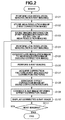
X-ray imaging apparatus 100 controls thedrive unit 102 and thereading unit 104 through thecontrol unit 101 to perform high-resolution imaging. In steps S102 and S103, theX-ray imaging apparatus 100 stores in the first correctionimage storage unit 122 an output (first correction image) of thereading unit 104 and relevant imaging information (first imaging information). The imaging information includes, for example, temperature, frame rate, electric charge accumulation time, elapsed time from the start of imaging, and so on. - Then, the
X-ray imaging apparatus 100 performs low-resolution imaging. In this case, X-ray irradiation is not performed similarly to the case of high-resolution imaging. When starting this imaging, theX-ray imaging apparatus 100 changes theswitch 130 through thecontrol unit 101 to connect theswitch 130 to the second correctionimage generation unit 123. Theswitch 131 is left disconnected from the offsetcorrection processing unit 105. - When this switching is completed, in step S104, the
X-ray imaging apparatus 100 controls thedrive unit 102 and thereading unit 104 through thecontrol unit 101 to perform low-resolution imaging. In step S105, theX-ray imaging apparatus 100 acquires an output (low-resolution image) of thereading unit 104 and then converts the acquired low-resolution image to a high resolution image through the second correctionimage generation unit 123. The second correctionimage generation unit 123 transmits the high-resolution image acquired with this conversion to the correctionfactor calculation unit 119 as the second correction image. - The
X-ray imaging apparatus 100 starts imaging through X-ray irradiation. In this case, theX-ray imaging apparatus 100 changes theswitches control unit 101. With this switching, theswitch 130 is adapted to disconnect thereading unit 104 from the first correctionimage generation unit 122 and the second correctionimage generation unit 123 and theswitch 131 is connected to the offsetcorrection processing unit 105. - When this switching is completed, in step S106, the
X-ray imaging apparatus 100 instructs theX-ray generation apparatus 200 through thecontrol unit 101 to perform X-ray irradiation, and controls thedrive unit 102 and thereading unit 104 to perform X-ray imaging. Then, theX-ray imaging apparatus 100 acquires an output (X-ray image) of thereading unit 104 and then transmits imaging information at the time of X-ray imaging (X-ray imaging information) to the correctionfactor calculation unit 119. - In step S107, upon reception of the imaging information, the correction
factor calculation unit 119 acquires the first and second correction factors by which the first and second correction images are to be multiplied, respectively. These correction factors are acquired based on the X-ray imaging information and the first imaging information. - More specifically, the correction factors are acquired based on a difference in a specific imaging parameter value between both pieces of imaging information. For example, it is possible to use one or more of differences in imaging temperature, imaging frame rate, electric charge accumulation time, elapsed time from the start of imaging, and so on.
- As the difference in a specific imaging parameter value,
formulas Fig. 3A use, for example, the difference in temperature (Δtemp) and the difference in electric charge accumulation time (Δtime). The second correction factor is acquired by the sum of the difference in temperature (Δtemp) multiplied by a predetermined factor "a" and the difference in electric charge accumulation time (Δtime) multiplied by a predetermined factor "b" (formula 1). - The first correction factor is acquired by subtracting the second correction factor from 1 (formula 2). That is, the
formula 1 derives a value of the second correction factor, which is between 0 and 1 (inclusive). - When the two correction factors are acquired in this way, the
X-ray imaging apparatus 100 generates an offset correction image through the correctionimage generation unit 120. When generating an offset correction image, the first correction image is multiplied by the first correction factor and the second correction image is multiplied by the second correction factor, and the two resultant values are added. In step S108, the offset correction image is acquired. - Then, the
X-ray imaging apparatus 100 corrects through the offsetcorrection processing unit 105 the X-ray image captured in step S106. More specifically, in step S109, the offsetcorrection processing unit 105 subtracts the offset correction image from the X-ray image to acquire an X-ray image from which the offset component has been removed. When this correction is completed, theX-ray imaging apparatus 100 transmits the corrected X-ray image to thedisplay unit 300. In step S110, thedisplay unit 300 displays the received X-ray image. - If X-ray imaging is performed again (YES in step S111), the processing returns to step S104. If imaging is terminated (NO in step S111), the processing in
Fig. 2 ends. - The first correction image captured and stored in steps S101 to S103 may be updated at a timing, for example, when the
X-ray imaging apparatus 100 is activated. However, the timing of updating is not limited thereto. - Although low-resolution imaging is performed in step S104 before X-ray imaging in step S106 in the description above, it is also possible to perform processing of steps S104 and S105 after step S106.
- The above-mentioned offset correction image generated in step S108 will be described below.
- When the imaging information at the time of first correction imaging (at the time of high-resolution imaging) nearly equals the imaging information at the time of X-ray imaging (i.e., with a small difference in an imaging parameter value between both pieces of imaging information), an offset correction image largely affected by the first correction image is acquired.
- When the imaging information at the time of first correction imaging largely differs from the imaging information at the time of X-ray imaging (i.e., with a large difference in an imaging parameter value between both pieces of imaging information), an offset correction image largely affected by the second correction image acquired (immediately) before X-ray imaging is acquired.
- For example, with a small difference in imaging temperature between both pieces of imaging information (Δtemp), the value of B (first correction factor) is large as illustrated in
Fig. 3C and therefore an offset correction image largely affected by the first correction image is acquired. - Conversely, with a large difference in temperature at the time of both imaging between both pieces of imaging information (Δtemp), the value of B (first correction factor) is small as illustrated in
Fig. 3C and therefore an offset correction image slightly affected by the first correction image is acquired. Also in the case of the difference in electric charge accumulation time (Δtime), a similar effect to the difference in temperature (Δtemp) described above is obtained, as illustrated inFig. 3B . - As described above, according to the first exemplary embodiment, a low-resolution image (second correction image (non-radiation imaging)) is captured at each time of radiation imaging, and an offset component is removed from the radiation image based on the low-resolution image and a high-resolution image (first correction image (non-radiation imaging)) captured in advance.
- Thus, the first exemplary embodiment makes it possible to quickly perform imaging as well as improves the image quality even with a configuration in which the offset correction image is updated at each time of radiation imaging.
- A second exemplary embodiment will be described below.
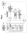
Fig. 4 is a block diagram illustrating an exemplary functional configuration of a radiation imaging system (hereinafter referred to as X-ray imaging system) according to the second exemplary embodiment. InFig. 4 , the same reference numerals are assigned to elements having the same function as those inFig. 1 illustrating the first exemplary embodiment, and duplicated explanations may be omitted. Differences from the first exemplary embodiment will be selectively described below. - The
X-ray imaging apparatus 100 according to the second exemplary embodiment includes acontrol unit 101, aimaging unit 106, an offsetcorrection processing unit 105, a correctionimage generation unit 120, and a correctionimage storage unit 124. TheX-ray imaging apparatus 100 also includesswitches 130 to 131. - The
X-ray imaging apparatus 100 according to the second exemplary embodiment generates an offset correction image in a different way from that according to the first exemplary embodiment. More specifically, areading unit 104 reads a part of pixel data in an imaging area, and the correctionimage generation unit 120 generates an offset correction image based on an output of thereading unit 104. In this case, X-ray irradiation is not performed. At the time of X-ray imaging, thereading unit 104 reads all the pixel data in the imaging area. - The correction
image storage unit 124 stores the offset correction image that includes information about a dark current. The correctionimage generation unit 120 updates the offset correction image at each time of X-ray imaging. - More specifically, the correction
image generation unit 120 combines the offset correction image stored in the correctionimage storage unit 124 with an image captured without X-ray irradiation to generate the offset correction image. The correctionimage storage unit 124 stores the generated offset correction image. - The offset
correction processing unit 105 performs such correction (offset correction) as to remove an offset component from the X-ray image, by using the offset correction image. More specifically, the offsetcorrection processing unit 105 subtracts the offset correction image stored in the correctionimage storage unit 124 from the output (X-ray image) of thereading unit 104 at the time of X-ray imaging. - An exemplary imaging operation in the X-ray imaging system according to the second exemplary embodiment will be described below with reference to
Fig. 5 . - The
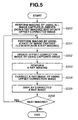
X-ray imaging apparatus 100 first performs imaging by driving all image capture elements. In this case, X-ray irradiation is not performed. When starting this imaging, theX-ray imaging apparatus 100 changes theswitches control unit 101. - With this switching, the
switch 130 is connected to the correctionimage generation unit 120 and theswitch 131 is disconnected from the offsetcorrection processing unit 105. When this switching is completed, theX-ray imaging apparatus 100 controls thedrive unit 102 and thereading unit 104 through thecontrol unit 101 to perform imaging. - In step S200, the
X-ray imaging apparatus 100 stores the output (image captured by all image capture elements) of thereading unit 104 in the correctionimage storage unit 124 through the correctionimage generation unit 120. - Then, the
X-ray imaging apparatus 100 performs imaging by driving a part of image capture elements. In this case, X-ray irradiation is not performed. When starting this imaging, theX-ray imaging apparatus 100 changes theswitches control unit 101. With this switching, theswitch 130 is connected to the correctionimage generation unit 120 and theswitch 131 is disconnected from the offsetcorrection processing unit 105. - When this switching is completed, in step S201, the
X-ray imaging apparatus 100 controls thedrive unit 102 and thereading unit 104 through thecontrol unit 101 to perform imaging. Then, theX-ray imaging apparatus 100 combines the output (image captured by a part of image capture elements) of thereading unit 104 with the offset correction image stored in the correctionimage storage unit 124 through the correctionimage generation unit 120. - The offset correction image is updated with this combination. In step S202, the updated offset correction image is stored in the correction
image storage unit 124. - Then, the
X-ray imaging apparatus 100 starts imaging through X-ray irradiation. In this case, theX-ray imaging apparatus 100 changes theswitches control unit 101. With this switching, theswitch 130 is disconnected from thereading unit 104 and theswitch 131 is connected to the offsetcorrection processing unit 105. - When this switching is completed, in step S203, the
X-ray imaging apparatus 100 instructs theX-ray generation apparatus 200 through thecontrol unit 101 to perform X-ray irradiation, and controls thedrive unit 102 and thereading unit 104 to perform X-ray imaging. Then, theX-ray imaging apparatus 100 acquires an output (X-ray image) of thereading unit 104. - Then, the
X-ray imaging apparatus 100 corrects the X-ray image captured in step S203 through the offsetcorrection processing unit 105. Specifically, in step S204, the offsetcorrection processing unit 105 subtracts the offset correction image from the X-ray image, thus acquiring an X-ray image from which the offset component is removed. - When this correction is completed, the
X-ray imaging apparatus 100 transmits the corrected X-ray image to adisplay unit 300. In step S205, thedisplay unit 300 displays the received X-ray image. - If X-ray imaging is performed again (YES in step S206), the processing returns to step S201. If imaging is terminated (NO in step S206), the processing in
Fig. 5 ends. - Imaging by using a part of the image capture elements in step S201 will be described below.
- Pixels in a captured image correspond to image capture elements on a one-to-one basis. As illustrated in
Fig. 6 , an image capture element group (matrix) is composed of a predetermined number of (in this case, four) image capture elements (pixels). - Although a square containing four image capture elements is defined as one image capture element group, the number of image capture elements in a group and its shape are not limited thereto but may be changed as required.
- In each matrix, each of the image capture elements is assigned a number. This number denotes the order of imaging (driving and reading) at each time of non-X-ray imaging.
- In a
matrix 701, for example, animage capture element 1 at the top left is activated for first non-X-ray imaging, and animage capture element 2 at the bottom left is activated for second non-X-ray imaging. Likewise, animage capture element 3 at the top right is activated for third non-X-ray imaging, and animage capture element 4 at the bottom right is activated for fourth non-X-ray imaging. TheX-ray imaging apparatus 100 repeats this sequence of four non-X-ray imaging operations by using different image capture elements in this way. - In a
matrix 702, for example, animage capture element 1 at the top right is activated for first non-X-ray imaging, and animage capture element 2 at the bottom right is activated for second non-X-ray imaging. Likewise, animage capture element 3 at the top left is activated for third non-X-ray imaging, and animage capture element 4 at the bottom left is activated for fourth non-X-ray imaging. - The above-mentioned two different types of matrices (
matrices 701 and 702) are vertically arranged in alternation while the same type of matrices are horizontally arranged. More specifically, in each of horizontally arranged matrices, image capture elements are activated for imaging in the same order. In each of vertically arranged matrices, image capture elements are activated for imaging in one of a plurality of (in this case, two) orders. - With the above-described imaging control, a different image capture element is used at each time of non-X-ray imaging, for example, in order of 1, 2, 3, and 4. In the horizontal direction, image capture elements are activated for imaging in an interlaced way at a time, as illustrated in
Fig. 7 . That is, the rows are alternately activated for imaging at each time of non-X-ray imaging. - If imaging is performed only with the
matrix 701 without using thematrix 702, image capture elements are activated for imaging, for example, in a way illustrated inFig. 8 . In this case, however, since any one row or column of pixels may not entirely be refreshed in the offset correction image, visible artifacts may be generated in the corrected X-ray image. - As described above, according to the second exemplary embodiment, a part of image capture elements are driven at each time of X-ray imaging to perform imaging (non-X-ray imaging), and then the prestored offset correction image is updated by using the captured image.
- Thus, similar to the first exemplary embodiment, the second exemplary embodiment makes it possible to quickly perform imaging and improve the image quality even with the configuration in which the offset correction image is updated at each time of X-ray imaging.
- Further, at the time of non-X-ray imaging, image capture elements in two different types of matrices are activated for imaging based on the order assigned to these image capture elements in each matrix and on the row position of each matrix. Then, the offset correction image is updated based on the result.
- This configuration makes it possible to acquire an offset correction image that enables more appropriate offset correction than a case without this configuration. Therefore, in a radiation image, noise due to an effect of the offset correction image can be suppressed.
- Although the present invention has specifically been described based on typical exemplary embodiments, the present invention is not limited thereto but may be modified as appropriate without departing from the scope of the invention.
- For example, in the configuration according to the second exemplary embodiment, it is also possible to update the offset correction image by using data for past several times of non-X-ray imaging. For example, data for each pixel for past several (for example, four) times of non-X-ray imaging and data for one image are stored in the correction
image storage unit 124. The correctionimage storage unit 124 deletes the oldest pixel data each time new pixel data is acquired. - At each time of non-X-ray imaging, the correction
image generation unit 120 obtains an average value for pixel data for past four times of imaging including the captured image and refreshes corresponding pixels in the offset correction image. According to this configuration, an X-ray image having little or no artifacts can be acquired. - The present invention can be embodied, for example, as a system, an apparatus, a method, a program, or a recording medium. More specifically, the present invention can be applied to a system including a plurality of devices or to an apparatus including only one device.
- Further, the present invention also includes a case where software or a program is directly or remotely supplied to a system or apparatus, and a computer built therein loads and executes the supplied program code, thus implementing the functions of the above-described exemplary embodiments. In this case, the supplied program is a computer program corresponding to the flow charts illustrated in
Figs 2 and5 . - Therefore, in order to implement the functional processing of the present invention by using a computer, the program code itself installed therein also attains the present invention. That is, the computer program itself for implementing the functional processing of the present invention is included in the present invention. In this case, the program may be supplied as an object code, a program executed by an interpreter, and script data supplied to an operating system (OS), as long as it functions as a program.
- A computer-readable recording medium for supplying the computer program may be, for example, a floppy disk, a hard disk, an optical disk, a magneto-optical disk (MO), a compact disk read-only memory (CD-ROM), a compact disk recordable (CD-R), a compact disk rewritable (CD-RW), a magnetic tape, a non-volatile memory card, a ROM, a digital versatile disk (DVD) including DVD-ROM and DVD-R, and so on.
- Further, the computer program can also be supplied, for example, from a homepage on the Internet by using a browser of a client computer and downloading the program of the present invention therefrom to a recording medium such as a hard disk. In this case, the program to be downloaded may be a compressed file having an automatic installation function.
- Further, the program of the present invention can also be supplied by splitting its program code into a plurality of files, and downloading each file from different homepages. That is, the present invention also includes a WWW server that allows a plurality of users to download program files for implementing the functional processing of the present invention.
- Further, the program of the present invention can also be delivered to users as an encrypted program stored in a recording medium such as a CD-ROM. In this case, it is also possible to allow a user satisfying predetermined conditions to download encryption key information from a homepage through the Internet, execute the encrypted program by using the encryption key information, and install the program in a computer.
- The functions of the above-mentioned exemplary embodiments are implemented when the computer loads and executes the program. Further, the functions of the above-mentioned exemplary embodiments may also be implemented in collaboration with the OS operating on the computer based on instructions of the program. In this case, for example, the OS performs a part or all of the actual processing, and the functions of the above-mentioned exemplary embodiments are implemented by the processing.
- Further, a part or all of the functions of the above-mentioned exemplary embodiments may be implemented by writing the program read from the recording medium to a memory built in a function expansion board inserted into the computer or a function expansion unit connected thereto. In this case, after the program has been written to the function expansion board or function expansion unit, a CPU built in the function expansion board or function expansion unit executes a part or all of the actual processing based on instructions of the program.
- It will of course be understood that this invention has been described above by way of example only, and that modifications of detail can be made within the scope of this invention.
Claims (14)
- A radiation imaging apparatus comprising:imaging means (106) configured to perform imaging by using a plurality of image capture elements for accumulating electric charges;storage means (124) configured to store information relating to a first offset correction image;correction image generation means (120) configured to modify the first offset correction image with a second offset correction image captured by the imaging means (106) without radiant-ray irradiation to update the first offset correction image; andcorrection processing means (105) configured to correct a radiation image captured through radiant-ray irradiation, based on the modified offset correction image;characterized in that the imaging means (106) is configured to capture the second offset correction image between each time of radiation imaging such that each radiation image is corrected based on the preceding modified offset correction image, and wherein the first offset correction image having a higher resolution than the second offset correction image.
- The radiation imaging apparatus according to claim 1, wherein the stored information relating to the first offset correction image includes information on one or more of the following: temperature, frame rate, electric charge accumulation time and elapsed time from start of imaging.
- The radiation imaging apparatus according to claim 1 or 2, wherein the correction processing means (105) is configured, when the information relating to the first offset correction image is substantially equal to the imaging information at the time of radiation imaging, to correct the radiation image, based substantially on the first offset correction image, and wherein the correction processing means (105) is configured, when the imaging information relating to the first offset correction image is substantially different from the imaging information at the time of radiation imaging, to correct the radiation image, based substantially on the second offset correction image.
- A radiation imaging apparatus comprising:imaging means (106) configured to perform imaging by using a plurality of image capture elements for accumulating electric charges;storage means (124) configured to store information relating to an offset correction image;correction image generation means (120) configured, when capturing a radiation image through radiant-ray irradiation, to combine the offset correction image with an image captured by using a part of the plurality of image capture elements through the imaging means (106) without radiant-ray irradiation to update the offset correction image; andcorrection processing means (105) configured to correct the radiation image captured through radiant-ray irradiation, based on the updated offset correction image.
- The radiation imaging apparatus according to claim 4, wherein the image capture elements correspond to pixels of the captured image on a one-to-one basis and a predetermined number of image capture elements are collected as a group, and
wherein, at each time of imaging by using a part of the plurality of image capture elements without radiant-ray irradiation, the imaging means is configured to perform imaging by sequentially activating image capture elements in each of the image capture element groups. - The radiation imaging apparatus according to claim 5, wherein the image capture elements are two-dimensionally arranged, and
wherein, when capturing an image by using a part of the plurality of image capture elements without radiant-ray irradiation, the imaging means is configured to activate image capture elements in the same order in each of horizontally arranged image capture element groups, and to activate image capture elements in one of a plurality of orders in each of vertically arranged image capture element groups. - The radiation imaging apparatus according to claim 6, wherein, at each time of imaging by using a part of the plurality of image capture elements without radiant-ray irradiation, the imaging means is configured to alternately select one row in each image capture element group.
- The radiation imaging apparatus according to any one of claims 4 to 7, wherein the correction image generation means is configured to acquire an average value from past data obtained as a result of imaging by using a part of the plurality of image capture elements without radiant-ray irradiation, and to update the offset correction image by using the average value.
- The radiation imaging apparatus according to any preceding claim, wherein the correction processing means is configured to correct the radiation image by subtracting the offset correction image from the radiation image.
- A processing method for a radiation imaging apparatus that performs imaging by using a plurality of image capture elements for accumulating electric charges, the method comprising:modifying a first offset correction image with a second offset correction image captured without radiant-ray irradiation to update the first offset correction image;correcting a radiation image captured through radiant-ray irradiation, based on the modified offset correction image, wherein the second offset correction image is captured between each time of radiation imaging such that each radiation image is corrected based on the preceding modified offset correction image and wherein the first offset correction image having a higher resolution than the second offset correction image.
- A processing method for a radiation imaging apparatus that performs imaging by using a plurality of image capture elements for accumulating electric charges, the method comprising:generating a correction image by combining, when capturing a radiation image through radiant-ray irradiation, an offset correction image stored in storage means with an image captured by using a part of the plurality of image capture elements without radiant-ray irradiation to update the offset correction image stored in the storage means; andperforming correction processing by correcting the radiation image captured through radiant-ray irradiation, based on the updated offset correction image.
- A program which, when executed by a computer, causes the computer to carry out the method of claim 10 or claim 11.
- A program which, when loaded into a computer, causes the computer to become the radiation processing apparatus of any one of claims 1 to 3 or the radiation processing apparatus of any one of claims 4 to 9.
- A storage medium storing the computer program according to claims 12 or 13.
Applications Claiming Priority (1)
| Application Number | Priority Date | Filing Date | Title |
|---|---|---|---|
| JP2009017130A JP5561938B2 (en) | 2009-01-28 | 2009-01-28 | Radiation imaging apparatus, processing method therefor, and radiation imaging system |
Publications (2)
| Publication Number | Publication Date |
|---|---|
| EP2214399A2 true EP2214399A2 (en) | 2010-08-04 |
| EP2214399A3 EP2214399A3 (en) | 2015-01-14 |
Family
ID=42144759
Family Applications (1)
| Application Number | Title | Priority Date | Filing Date |
|---|---|---|---|
| EP10151817.3A Withdrawn EP2214399A3 (en) | 2009-01-28 | 2010-01-27 | Radiation imaging apparatus, processing method therefor, and radiation imaging system |
Country Status (4)
| Country | Link |
|---|---|
| US (2) | US8097858B2 (en) |
| EP (1) | EP2214399A3 (en) |
| JP (1) | JP5561938B2 (en) |
| KR (1) | KR101235260B1 (en) |
Cited By (2)
| Publication number | Priority date | Publication date | Assignee | Title |
|---|---|---|---|---|
| CN102670222A (en) * | 2011-03-07 | 2012-09-19 | 佳能株式会社 | Radiation imaging apparatus and method for controlling same |
| EP2663879B1 (en) * | 2011-01-10 | 2017-08-02 | Koninklijke Philips N.V. | Detection device for detecting photons emitted by a radiation source |
Families Citing this family (7)
| Publication number | Priority date | Publication date | Assignee | Title |
|---|---|---|---|---|
| JP5371638B2 (en) * | 2009-09-01 | 2013-12-18 | キヤノン株式会社 | Ophthalmic imaging apparatus and method |
| JP2012083307A (en) * | 2010-10-14 | 2012-04-26 | Fujifilm Corp | Radiation detection device, radiation image photographing system, radiation detection program and radiation detection method |
| JP2012095711A (en) * | 2010-10-29 | 2012-05-24 | Hitachi Medical Corp | Image processor, image processing method, and x-ray image diagnostic apparatus |
| JP6491432B2 (en) * | 2014-08-08 | 2019-03-27 | キヤノン株式会社 | Radiation imaging apparatus and control method thereof |
| JP6853644B2 (en) * | 2016-09-30 | 2021-03-31 | キヤノン株式会社 | Radiation imaging device, radiation imaging system, radiation imaging method and program |
| JP6890443B2 (en) * | 2017-03-22 | 2021-06-18 | キヤノン株式会社 | Radiation imaging system, radiography method, and program |
| KR102259845B1 (en) | 2019-12-17 | 2021-06-03 | 한국원자력연구원 | Apparatus and method for image compensation |
Citations (1)
| Publication number | Priority date | Publication date | Assignee | Title |
|---|---|---|---|---|
| JP2008036405A (en) | 2006-07-11 | 2008-02-21 | Canon Inc | Radiation imaging apparatus, driving method thereof and radiation imaging system |
Family Cites Families (4)
| Publication number | Priority date | Publication date | Assignee | Title |
|---|---|---|---|---|
| US20030223539A1 (en) * | 2002-05-31 | 2003-12-04 | Granfors Paul R. | Method and apparatus for acquiring and storing multiple offset corrections for amorphous silicon flat panel detector |
| JP4546174B2 (en) * | 2004-07-15 | 2010-09-15 | キヤノン株式会社 | Imaging apparatus, control method therefor, and program |
| JP4744831B2 (en) * | 2004-09-09 | 2011-08-10 | 株式会社東芝 | X-ray diagnostic equipment |
| JP5371638B2 (en) * | 2009-09-01 | 2013-12-18 | キヤノン株式会社 | Ophthalmic imaging apparatus and method |
-
2009
- 2009-01-28 JP JP2009017130A patent/JP5561938B2/en active Active
-
2010
- 2010-01-20 KR KR1020100005036A patent/KR101235260B1/en active IP Right Grant
- 2010-01-26 US US12/693,889 patent/US8097858B2/en not_active Expired - Fee Related
- 2010-01-27 EP EP10151817.3A patent/EP2214399A3/en not_active Withdrawn
-
2011
- 2011-12-07 US US13/313,381 patent/US8258463B2/en not_active Expired - Fee Related
Patent Citations (1)
| Publication number | Priority date | Publication date | Assignee | Title |
|---|---|---|---|---|
| JP2008036405A (en) | 2006-07-11 | 2008-02-21 | Canon Inc | Radiation imaging apparatus, driving method thereof and radiation imaging system |
Cited By (6)
| Publication number | Priority date | Publication date | Assignee | Title |
|---|---|---|---|---|
| EP2663879B1 (en) * | 2011-01-10 | 2017-08-02 | Koninklijke Philips N.V. | Detection device for detecting photons emitted by a radiation source |
| CN102670222A (en) * | 2011-03-07 | 2012-09-19 | 佳能株式会社 | Radiation imaging apparatus and method for controlling same |
| CN102670222B (en) * | 2011-03-07 | 2015-01-28 | 佳能株式会社 | Radiation imaging apparatus and method for controlling same |
| CN104605873A (en) * | 2011-03-07 | 2015-05-13 | 佳能株式会社 | X-ray shooting apparatus and control method for controlling X-ray shooting |
| US9615811B2 (en) | 2011-03-07 | 2017-04-11 | Canon Kabushiki Kaisha | Radiation imaging apparatus and method for controlling the same |
| CN104605873B (en) * | 2011-03-07 | 2018-01-05 | 佳能株式会社 | X ray picture pick-up device and the control device and method of control X ray shooting |
Also Published As
| Publication number | Publication date |
|---|---|
| EP2214399A3 (en) | 2015-01-14 |
| US20100187410A1 (en) | 2010-07-29 |
| US8258463B2 (en) | 2012-09-04 |
| US20120074328A1 (en) | 2012-03-29 |
| JP2010172429A (en) | 2010-08-12 |
| US8097858B2 (en) | 2012-01-17 |
| JP5561938B2 (en) | 2014-07-30 |
| KR101235260B1 (en) | 2013-02-22 |
| KR20100087639A (en) | 2010-08-05 |
Similar Documents
| Publication | Publication Date | Title |
|---|---|---|
| US8258463B2 (en) | Radiation imaging apparatus, processing method therefor, and radiation imaging system | |
| US7724874B2 (en) | Radiation imaging apparatus, driving method thereof and radiation imaging system | |
| US10416323B2 (en) | Radiation imaging apparatus, radiation imaging system, and method of operating radiation imaging apparatus | |
| US7139364B2 (en) | X-ray-tomographic imaging apparatus, X-ray-tomographic imaging method, and program | |
| CN102670222B (en) | Radiation imaging apparatus and method for controlling same | |
| JP4931238B2 (en) | Imaging apparatus and driving method thereof | |
| US20160104733A1 (en) | Image pickup apparatus and radiation image pickup system | |
| JP4155921B2 (en) | X-ray diagnostic imaging equipment | |
| JP5539139B2 (en) | IMAGING DEVICE, IMAGING SYSTEM, AND IMAGING DEVICE CONTROL METHOD | |
| JP4258832B2 (en) | X-ray diagnostic imaging equipment | |
| US20070291900A1 (en) | Method for generating at least one offset-corrected x-ray image | |
| US11128816B2 (en) | Radiographic imaging system | |
| JP5057543B2 (en) | Image processing apparatus, control method therefor, and program | |
| US7129499B2 (en) | Radiographic apparatus and radiographic method | |
| JP2006239117A (en) | Radiographic device | |
| JP6852287B2 (en) | Radiation imaging equipment and radiation imaging system | |
| JP2005028113A (en) | Radiographic apparatus and radiographic method | |
| US20220060643A1 (en) | Solid-state imaging device, driving method, and electronic device | |
| JP4029337B2 (en) | Radiation imaging device | |
| JP7508509B2 (en) | Radiation imaging apparatus, radiation imaging system, and method and program for controlling radiation imaging apparatus | |
| JP2024049761A (en) | Radiation imaging apparatus | |
| JP2013223554A (en) | Radiographic imaging apparatus and radiographic imaging system | |
| JP2020054671A (en) | Image display device, radiation image capturing system, and program |
Legal Events
| Date | Code | Title | Description |
|---|---|---|---|
| PUAI | Public reference made under article 153(3) epc to a published international application that has entered the european phase |
Free format text: ORIGINAL CODE: 0009012 |
|
| AK | Designated contracting states |
Kind code of ref document: A2 Designated state(s): AT BE BG CH CY CZ DE DK EE ES FI FR GB GR HR HU IE IS IT LI LT LU LV MC MK MT NL NO PL PT RO SE SI SK SM TR |
|
| AX | Request for extension of the european patent |
Extension state: AL BA RS |
|
| PUAL | Search report despatched |
Free format text: ORIGINAL CODE: 0009013 |
|
| AK | Designated contracting states |
Kind code of ref document: A3 Designated state(s): AT BE BG CH CY CZ DE DK EE ES FI FR GB GR HR HU IE IS IT LI LT LU LV MC MK MT NL NO PL PT RO SE SI SK SM TR |
|
| AX | Request for extension of the european patent |
Extension state: AL BA RS |
|
| RIC1 | Information provided on ipc code assigned before grant |
Ipc: H04N 5/32 20060101ALI20141210BHEP Ipc: H04N 5/217 20110101AFI20141210BHEP |
|
| STAA | Information on the status of an ep patent application or granted ep patent |
Free format text: STATUS: THE APPLICATION HAS BEEN WITHDRAWN |
|
| 18W | Application withdrawn |
Effective date: 20150217 |