EP2214386A1 - Communication apparatus - Google Patents
Communication apparatus Download PDFInfo
- Publication number
- EP2214386A1 EP2214386A1 EP08851504A EP08851504A EP2214386A1 EP 2214386 A1 EP2214386 A1 EP 2214386A1 EP 08851504 A EP08851504 A EP 08851504A EP 08851504 A EP08851504 A EP 08851504A EP 2214386 A1 EP2214386 A1 EP 2214386A1
- Authority
- EP
- European Patent Office
- Prior art keywords
- circuit board
- communication
- communication module
- main circuit
- signal
- Prior art date
- Legal status (The legal status is an assumption and is not a legal conclusion. Google has not performed a legal analysis and makes no representation as to the accuracy of the status listed.)
- Withdrawn
Links
Images


Classifications
-
- G—PHYSICS
- G07—CHECKING-DEVICES
- G07F—COIN-FREED OR LIKE APPARATUS
- G07F9/00—Details other than those peculiar to special kinds or types of apparatus
- G07F9/02—Devices for alarm or indication, e.g. when empty; Advertising arrangements in coin-freed apparatus
- G07F9/026—Devices for alarm or indication, e.g. when empty; Advertising arrangements in coin-freed apparatus for alarm, monitoring and auditing in vending machines or means for indication, e.g. when empty
Definitions
- the present invention relates to a communication apparatus used in the field of telemetering used for such purposes as collection of sales information from vending machines or the field of telematics used for distribution of traffic information to mobile objects or the like.
- the telemetering originally refers to a system for reading a measured value by a measurement instrument via a communication line. However, it has been generally used as a term indicating not only reading data but also monitoring the operation of equipment and performing remote control.
- a typical application of telemetering can be a sales management system of a vending machine, used amount management system of a gas, water supply, etc., and a management system for unmanned parking lots, etc.
- For a sales management system of a vending machine refer to the patent document 1.
- the telematics refers to providing information service in real time by combining a mobile object such as an automobile with a communication system.
- a typical application of telematics can be a vehicle-mounted information system etc. for providing a terminal provided on a vehicle with traffic information and navigation information in real time.
- a user in a remote location would require Data Circuit-terminating Equipment (DCE) and Data Terminal Equipment (DTE) using the Data Circuit-terminating Equipment.
- DCE Data Circuit-terminating Equipment
- DTE Data Terminal Equipment
- the Data Terminal Equipment corresponds to a control device for controlling sales processes and inside temperature.
- the Data Terminal Equipment connects to a predetermined network via the Data Circuit-terminating Equipment regularly or at random timing, and connects to a predetermined management computer via the network. And then the Data Terminal Equipment connected to the management computer transmits various sets of data relating to the objects to be controlled.
- a communication apparatus comprising Data Circuit-terminating Equipment and a communication controller which intervene between the Data Circuit-terminating Equipment and Data Terminal Equipment, is proposed (see the patent document 2).
- This communication apparatus comprises, in a case, a main circuit board on which the communication controller is mounted and an auxiliary circuit board on which the Data Circuit-terminating Equipment is mounted.
- the main circuit board is connected to the auxiliary circuit board by a signal line detachably.
- the communication controller performs communication controls such as protocol conversion, address conversion, authentication proxy and connection process in order to absorb differences of plural kind of Data Circuit-terminating Equipments, carriers and services.
- the communication apparatus provides that Data Circuit-terminating Equipment can be replaced along with the auxiliary circuit board without changing and modifying the Data Terminal Equipment.
- the communication controller performs behavior corresponding to a type of the Data Circuit-terminating Equipment. Accordingly the communication controller needs to detect the type of the connected Data Circuit-terminating Equipment.
- the patent document 2 discloses a method for recognizing of which a memory or a switch for recognition is provided on the auxiliary circuit board and the communication controller of the main circuit board reads values of the memory or the switch. And the patent document 2 discloses another method for recognizing that the communication controller identifies the type based on contents of communication messages with the Data Circuit-terminating Equipment.
- the former method has a problem that the number of the types transmittable from the auxiliary circuit board to the main circuit board is limited, because the number of the signal lines connecting between the main circuit board and the auxiliary circuit board is limited.
- the latter method is premised on that the communication controller can communicate basically to the Data Circuit-terminating Equipment. That is, it is premised on that initial process for communicating to the Data Circuit-terminating Equipment is completed. However it may be impossible to start the initial process if the type of the Data Circuit-terminating Equipment can not be obtained because the initial process depends on the hardware specification.
- the present invention has an object to provide a communication apparatus capable of performing initial process certainly with simple structure.
- the present application proposes a communication apparatus comprising a communication module that serves as Data Circuit-terminating Equipment used in a radio packet communication network; an auxiliary circuit board on which said communication module is mounted; a main circuit board on which a communication controller is mounted; and a signal line for connecting said main circuit board to the auxiliary circuit board detachably; wherein said main circuit board further comprises a detecting means for detecting a type of the connected communication module based on a signal status on the signal line at a start-up, and said communication controller performs a communication control operation in accordance with a result of detection by the detecting means.
- the signal status of the signal line at the start-up varies depending on the type of the communication modules.
- the present invention utilizes such characteristic of the communication module so that the detecting means detects the type of the connected communication module based on the pattern of the signal status on the signal line at the start-up. This provides that the type of the communication modules can be detected without any additional exclusive signal lines. Therefore a certain initial process can be performed.
- the present application also proposes the communication apparatus wherein said detecting means includes an encoding circuit for converting the pattern of the signal status on the signal line to a numerical value.
- said detecting means includes an encoding circuit for converting the pattern of the signal status on the signal line to a numerical value.
- the detecting means detects the type of the connected communication module based on the pattern of the signal status of the signal line at the start-up. This provides that the type of the communication modules can be detected without any additional exclusive signal lines. Therefore an initial process can be performed certainly with simple structure.
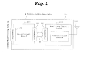
- FIG. 1 shows a schematic configuration diagram of the communication apparatus.
- Fig. 2 shows a block diagram of a main circuit board.
- Fig. 3 and Fig. 4 show a block diagram of an auxiliary circuit board.
- the communication apparatus 1 comprises, as shown in Fig. 1 , a main circuit board 100 and an auxiliary circuit board 200 in a case 10.
- a connector 101 for connecting to the auxiliary circuit board 200, and a connector 102 for connecting to Data Terminal Equipment are mounted on the main circuit board 100.
- a connector 201 for connecting to the main circuit board 100 is mounted on the auxiliary circuit board 200.
- the connector 101 of the main circuit board 100 and the connector 201 of the auxiliary circuit board 200 are connected by a flat cable 20 including plural signal lines detachably.
- a communication module 400 which is Data Circuit-terminating Equipment for a radio packet communication network, is mounted on the auxiliary circuit board 200.
- the communication module 400 connects to an antenna 500 arranged outside the case 10 via a connector (not shown).
- the main circuit board 100 comprises, as shown in Fig. 2 , an interface circuit 110 for the auxiliary circuit board 200, an interface circuit 115 for the Data Terminal Equipment, a communication controller 120, a detecting part 130 for detecting a type of the communication module 400.
- the interface circuit 110 for the auxiliary circuit board 200 is connected to the connector 101 via a bus line 140.
- the interface circuit 115 for the Data Terminal Equipment is connected to the connection controller 120 via a bus line 142.
- the interface circuit 115 for the Data Terminal Equipment is connected to the connector 102 via a bus line 144.
- the interface circuit 110 for the auxiliary circuit board 200, the connection controller 120 and the detecting part 130 are packaged in a FPGA (Field Programmable Gate Array) chip 150, which is a kind of a PLD (Programmable Logic Device).
- FPGA Field Programmable Gate Array
- the communication controller 120 performs a relay control of communications of the Data Terminal Equipment with the communication module 400, and performs communication controls such as protocol conversion, address conversion, authentication proxy and connection process as the needs arise. For instance, if the Data Terminal Equipment does not support services and protocols of the radio packet communication network to which the communication module 400 is to be connects, the communication controller 120 performs process to absorb the difference of the services and equipments such as address conversion process and authentication proxy process on behalf of the Data Terminal Equipment. This provides that any kind of network services can be used without changing or modifying the Data Terminal Equipment.
- the communication controller 120 supports two types of communication module 400 named a first communication module 400A and a second communication module 400B. And the communication module 400 has two process modes corresponding to the each module.
- the communication controller 120 has a general-purpose process mode in preparation for the case where the communication controller 120 is unable to detect the type of the connected communication module 400.
- the communication controller 120 changes its process mode in accordance with the type of the communication module 400 which the detecting part 130 detected.
- the detecting part 130 is inputted to signal lines which transmit signals from the auxiliary circuit board 200 to the FPGA chip 150 of which the signal lines is a part of the bus line 140 which is connected between the connector 201 for the auxiliary circuit board 200 and the FPGA chip 150.
- the signal lines inputting to the detecting part 130 include signal lines which transmit signals common with a plural types of the communication module 400.
- the signal lines can be a RD (Receive Data) signal, a CS (Clear to Send) signal, a CD (Carrier Detect) signal, a CI (Call Indicate) signal and a DR (Dataset Ready) signal.
- the signal lines inputted to the detecting part 130 can include signal lines which transmit peculiar signals to the communication module.
- the signal lines can be a signal line which transmits a signal relevant to the radio field intensity.
- the detecting part 130 acquires a signal status of said signal lines as the inputs at the start-up, and outputs a value corresponding to the type of the communication module 400 to the communication controller 120. That is, the detecting part 130 functions as an encoding circuit, wherein the input is the signal status of said signal lines and the encoding circuit converts a pattern of the signal status to a numerical value. In other word, if the pattern of the signal status matches a specific pattern, the detecting part 130 outputs a numerical value corresponding to the pattern.
- the plural patterns of the signal status are set up in advance so that the each pattern corresponds to each type of communication module 400.
- the signal status of the said signal lines means a voltage level of the signal. For instance, if the signal status of a pin number (2, 3, 5, 6) of the connector 201 shows a first pattern (Low, Low, High, Low), the detecting part 130 outputs "1" as the value corresponding to the first communication module 400A. And if the signal status shows a second pattern (High, High, High, Low), the detecting part 130 outputs "2" as the value corresponding to the second communication module 400B. And if the signal status does not match to any patterns, the detecting part 130 outputs the specific value, for example "0", which means failure of the detection.
- Fig. 3 shows a block diagram of the auxiliary circuit board 200A on which the first communication module 400A is mounted.
- Fig. 4 shows a block diagram of the auxiliary circuit board 200B on which the second communication module 400B is mounted.
- the connector 201A for connecting to the main circuit board 100 is mounted on the auxiliary circuit board 200A.
- a connector 202A for connecting to the first communication module 400A is mounted on the auxiliary circuit board 200A.
- a bus line 210A connects the connector 201A with the connector 202A.
- An interface circuit 220A is mounted on the bus line 210A.
- the interface circuit 220A has functions of a pull-up, noise elimination, a backflow prevention, and etc.
- pin assignments of the connector 201A and the connector 202A are converted by the wiring of the bus line 210A.
- the auxiliary circuit board 200B comprises a connector 201B for connecting to the main circuit board 100, a connector 202B for connecting to the second communication module 400B, a bus line 210B for connecting between the connector 201B and the connector 202B and a interface circuit 220B mounted on the bus line 210B.
- the interface circuit 220B has functions of a pull-up, noise elimination, a backflow prevention, and etc.
- pin assignments of the connector 201B and the connector 202B are converted by the wiring of the bus line 210B.
- a memory chip 230B is mounted on the auxiliary circuit board 200B.
- the memory chip 230B memorizes setting information such as telephone number information of the second communication module 400B.
- the memory chip 230B is required by specifications of the second communication module 400B.
- the memory chip 230B is connected to the second communication module 400B via a bus line 235B and the connector 202B.
- the detecting part 130 acquires the signal status of each input signal lines of the bus line 140 which is extended from the connector 101, as the input, and outputs the encoded value to the communication controller 120 (step S1).
- the communication controller 120 acquires the encoded output from the detecting part 130 (step S2). Next, if the encoded value corresponds to the first communication module 400A, the communication controller 120 will enter to the process mode corresponding to the first communication module 400A (step S3, S4). And if the encoded value corresponds to the second communication module 400B, the communication controller 120 will enter to the process mode corresponding to the second communication module 400B (step S5, S6). On the other hand, if the encoded value is the specific value indicating the failure of detection, the communication controller 120 will enter to the general-purpose process mode (step S7, S8). And in each process mode, the communication controller 120 performs an initial process for the communication module 400.
- the communication apparatus 1 of this embodiment provides that the communication controller 120 of the main circuit board 100 can perform the process mode certainly corresponding to the type of the communication module 400 mounted on the auxiliary circuit board 200. Especially the communication apparatus 1 of this embodiment enables to detect the communication module 400 without increasing signal lines connected between the main circuit board 100 and the auxiliary circuit board 200. Therefore the communication apparatus 1 can be designed with simple structure. This is useful if the communication apparatus 1 must support a lot of the communication modules 400. And in this embodiment, since the detecting part 130 is packaged in the FPGA together with the communication controller 120 as a logic circuit, the communication apparatus 1 can be designed with a small number of parts and simple structure.
- the communication controller 120 can further detect a detailed type of the communication module 400 in the process mode corresponding to the operation of the each communication module 400 after the communication controller 120 entered to the process mode on the basis of the result of the detecting part 130. In this additional detecting process, the communication controller 120 detects the detailed type on basis of the replay patterns in response to the command, when communicating with the communication module 400.
Landscapes
- Business, Economics & Management (AREA)
- Accounting & Taxation (AREA)
- Physics & Mathematics (AREA)
- General Physics & Mathematics (AREA)
- Communication Control (AREA)
- Telephone Function (AREA)
- Telephonic Communication Services (AREA)
Abstract
A communication apparatus comprising a communication module 400 that serves as Data Circuit-terminating Equipment used in a radio packet communication network; an auxiliary circuit board 200 on which said communication module 400 is mounted; a main circuit board 100 on which a communication controller 120 is mounted; and a signal line 20 for connecting said main circuit board 100 to the auxiliary circuit board 200 detachably; wherein said main circuit board 100 further comprises a detecting means 130 for detecting a type of the connected communication module 400 based on a pattern of a signal status on the signal line 20 at a start-up, and said communication controller 120 performs a communication control operation in accordance with a result of detection by the detecting means 130.
Description
- The present invention relates to a communication apparatus used in the field of telemetering used for such purposes as collection of sales information from vending machines or the field of telematics used for distribution of traffic information to mobile objects or the like.
- Recently, telemetering and telematics for collecting and distributing information over a radio packet communication network have become widespread. The telemetering originally refers to a system for reading a measured value by a measurement instrument via a communication line. However, it has been generally used as a term indicating not only reading data but also monitoring the operation of equipment and performing remote control. A typical application of telemetering can be a sales management system of a vending machine, used amount management system of a gas, water supply, etc., and a management system for unmanned parking lots, etc. For a sales management system of a vending machine, refer to the
patent document 1. The telematics refers to providing information service in real time by combining a mobile object such as an automobile with a communication system. A typical application of telematics can be a vehicle-mounted information system etc. for providing a terminal provided on a vehicle with traffic information and navigation information in real time. - In such fields, a user in a remote location would require Data Circuit-terminating Equipment (DCE) and Data Terminal Equipment (DTE) using the Data Circuit-terminating Equipment. In the sales management system of a vending machine, for instance, the Data Terminal Equipment corresponds to a control device for controlling sales processes and inside temperature. The Data Terminal Equipment connects to a predetermined network via the Data Circuit-terminating Equipment regularly or at random timing, and connects to a predetermined management computer via the network. And then the Data Terminal Equipment connected to the management computer transmits various sets of data relating to the objects to be controlled.
- In recent years, there have been requests to change the carrier of the radio packet communication network and its services after having constructed such system. However if the carrier and the services are changed, the Data Circuit-terminating Equipment also must be changed. Therefore the Data Terminal Equipment also must be changed or modified. Since the Data Terminal Equipments are located at various distant places, if a lot of Data Terminal Equipments are already installed in market, a workload for the changes and the modification of the Data Terminal Equipments is heavy. And similar problems may arise in case of model changes of the Data Terminal Equipment even if the carrier and the services are not changed. Further such problems will arise in case of future changes of the carrier, services and model. Therefore it is important to circumspectly select the carrier, services and model.
- To solve such problems, a communication apparatus comprising Data Circuit-terminating Equipment and a communication controller which intervene between the Data Circuit-terminating Equipment and Data Terminal Equipment, is proposed (see the patent document 2). This communication apparatus comprises, in a case, a main circuit board on which the communication controller is mounted and an auxiliary circuit board on which the Data Circuit-terminating Equipment is mounted. The main circuit board is connected to the auxiliary circuit board by a signal line detachably. The communication controller performs communication controls such as protocol conversion, address conversion, authentication proxy and connection process in order to absorb differences of plural kind of Data Circuit-terminating Equipments, carriers and services. The communication apparatus provides that Data Circuit-terminating Equipment can be replaced along with the auxiliary circuit board without changing and modifying the Data Terminal Equipment.
- PATENT DOCUMENT 1: Japanese Patent Publication
2003-51056 - PATENT DOCUMENT 2: Japanese Patent Publication
2006-245956 - As described above, in the apparatus of the
patent document 2, the communication controller performs behavior corresponding to a type of the Data Circuit-terminating Equipment. Accordingly the communication controller needs to detect the type of the connected Data Circuit-terminating Equipment. Thepatent document 2 discloses a method for recognizing of which a memory or a switch for recognition is provided on the auxiliary circuit board and the communication controller of the main circuit board reads values of the memory or the switch. And thepatent document 2 discloses another method for recognizing that the communication controller identifies the type based on contents of communication messages with the Data Circuit-terminating Equipment. - However the former method has a problem that the number of the types transmittable from the auxiliary circuit board to the main circuit board is limited, because the number of the signal lines connecting between the main circuit board and the auxiliary circuit board is limited. On the other hand the latter method is premised on that the communication controller can communicate basically to the Data Circuit-terminating Equipment. That is, it is premised on that initial process for communicating to the Data Circuit-terminating Equipment is completed. However it may be impossible to start the initial process if the type of the Data Circuit-terminating Equipment can not be obtained because the initial process depends on the hardware specification.
- In view of the above problems in the conventional art, the present invention has an object to provide a communication apparatus capable of performing initial process certainly with simple structure.
- In order to achieve the object stated above, the present application proposes a communication apparatus comprising a communication module that serves as Data Circuit-terminating Equipment used in a radio packet communication network; an auxiliary circuit board on which said communication module is mounted; a main circuit board on which a communication controller is mounted; and a signal line for connecting said main circuit board to the auxiliary circuit board detachably; wherein said main circuit board further comprises a detecting means for detecting a type of the connected communication module based on a signal status on the signal line at a start-up, and said communication controller performs a communication control operation in accordance with a result of detection by the detecting means.
- The signal status of the signal line at the start-up varies depending on the type of the communication modules. The present invention utilizes such characteristic of the communication module so that the detecting means detects the type of the connected communication module based on the pattern of the signal status on the signal line at the start-up. This provides that the type of the communication modules can be detected without any additional exclusive signal lines. Therefore a certain initial process can be performed.
- As a preferable example of the invention, the present application also proposes the communication apparatus wherein said detecting means includes an encoding circuit for converting the pattern of the signal status on the signal line to a numerical value. This invention provides that the type of the communication modules can be detected as numerical value. Therefore the initial process can be performed certainly and simply.
- Other objects, configurations, and advantages of the present invention will be made apparent in the following detailed descriptions.
- As described above, according to the present invention, the detecting means detects the type of the connected communication module based on the pattern of the signal status of the signal line at the start-up. This provides that the type of the communication modules can be detected without any additional exclusive signal lines. Therefore an initial process can be performed certainly with simple structure.
-
-
Fig. 1 shows a schematic configuration diagram of the communication apparatus; -
Fig. 2 shows a block diagram of a main circuit board; -
Fig. 3 shows a block diagram of an auxiliary circuit board; -
Fig. 4 shows a block diagram of an auxiliary circuit board; -
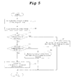
Fig. 5 shows a flow chart of an operation of the communication apparatus. -
- 1
- communication apparatus
- 10
- case
- 20
- flat cable
- 100
- main circuit board
- 101,102
- connector
- 110,115
- interface circuit
- 120
- communication controller
- 130
- detecting part
- 140
- bus line
- 200
- auxiliary circuit board
- 201,202
- connector
- 210
- bus line
- 220
- interface circuit
- 230B
- memory chip
- 400
- communication module
- 500
- antenna
- A communication apparatus, which is one embodiment of the present invention, will be described with reference to accompanying drawings.
Fig. 1 shows a schematic configuration diagram of the communication apparatus.Fig. 2 shows a block diagram of a main circuit board.Fig. 3 and Fig. 4 show a block diagram of an auxiliary circuit board. - The
communication apparatus 1 comprises, as shown inFig. 1 , amain circuit board 100 and anauxiliary circuit board 200 in acase 10. Aconnector 101 for connecting to theauxiliary circuit board 200, and aconnector 102 for connecting to Data Terminal Equipment are mounted on themain circuit board 100. Aconnector 201 for connecting to themain circuit board 100 is mounted on theauxiliary circuit board 200. Theconnector 101 of themain circuit board 100 and theconnector 201 of theauxiliary circuit board 200 are connected by aflat cable 20 including plural signal lines detachably. A communication module 400, which is Data Circuit-terminating Equipment for a radio packet communication network, is mounted on theauxiliary circuit board 200. The communication module 400 connects to anantenna 500 arranged outside thecase 10 via a connector (not shown). - The
main circuit board 100 comprises, as shown inFig. 2 , aninterface circuit 110 for theauxiliary circuit board 200, aninterface circuit 115 for the Data Terminal Equipment, acommunication controller 120, a detectingpart 130 for detecting a type of the communication module 400. Theinterface circuit 110 for theauxiliary circuit board 200 is connected to theconnector 101 via abus line 140. And theinterface circuit 115 for the Data Terminal Equipment is connected to theconnection controller 120 via abus line 142. And theinterface circuit 115 for the Data Terminal Equipment is connected to theconnector 102 via abus line 144. In this embodiment, theinterface circuit 110 for theauxiliary circuit board 200, theconnection controller 120 and the detectingpart 130 are packaged in a FPGA (Field Programmable Gate Array)chip 150, which is a kind of a PLD (Programmable Logic Device). - The
communication controller 120 performs a relay control of communications of the Data Terminal Equipment with the communication module 400, and performs communication controls such as protocol conversion, address conversion, authentication proxy and connection process as the needs arise. For instance, if the Data Terminal Equipment does not support services and protocols of the radio packet communication network to which the communication module 400 is to be connects, thecommunication controller 120 performs process to absorb the difference of the services and equipments such as address conversion process and authentication proxy process on behalf of the Data Terminal Equipment. This provides that any kind of network services can be used without changing or modifying the Data Terminal Equipment. In this embodiment, thecommunication controller 120 supports two types of communication module 400 named afirst communication module 400A and asecond communication module 400B. And the communication module 400 has two process modes corresponding to the each module. Further thecommunication controller 120 has a general-purpose process mode in preparation for the case where thecommunication controller 120 is unable to detect the type of the connected communication module 400. Thecommunication controller 120 changes its process mode in accordance with the type of the communication module 400 which the detectingpart 130 detected. - The detecting
part 130 is inputted to signal lines which transmit signals from theauxiliary circuit board 200 to theFPGA chip 150 of which the signal lines is a part of thebus line 140 which is connected between theconnector 201 for theauxiliary circuit board 200 and theFPGA chip 150. The signal lines inputting to the detectingpart 130 include signal lines which transmit signals common with a plural types of the communication module 400. For example, the signal lines can be a RD (Receive Data) signal, a CS (Clear to Send) signal, a CD (Carrier Detect) signal, a CI (Call Indicate) signal and a DR (Dataset Ready) signal. Additionally the signal lines inputted to the detectingpart 130 can include signal lines which transmit peculiar signals to the communication module. For example, the signal lines can be a signal line which transmits a signal relevant to the radio field intensity. The detectingpart 130 acquires a signal status of said signal lines as the inputs at the start-up, and outputs a value corresponding to the type of the communication module 400 to thecommunication controller 120. That is, the detectingpart 130 functions as an encoding circuit, wherein the input is the signal status of said signal lines and the encoding circuit converts a pattern of the signal status to a numerical value. In other word, if the pattern of the signal status matches a specific pattern, the detectingpart 130 outputs a numerical value corresponding to the pattern. The plural patterns of the signal status are set up in advance so that the each pattern corresponds to each type of communication module 400. Here, the signal status of the said signal lines means a voltage level of the signal. For instance, if the signal status of a pin number (2, 3, 5, 6) of theconnector 201 shows a first pattern (Low, Low, High, Low), the detectingpart 130 outputs "1" as the value corresponding to thefirst communication module 400A. And if the signal status shows a second pattern (High, High, High, Low), the detectingpart 130 outputs "2" as the value corresponding to thesecond communication module 400B. And if the signal status does not match to any patterns, the detectingpart 130 outputs the specific value, for example "0", which means failure of the detection. - Next, the
auxiliary circuit board 200 will be described with reference toFig. 3 and Fig. 4. Fig. 3 shows a block diagram of theauxiliary circuit board 200A on which thefirst communication module 400A is mounted.Fig. 4 shows a block diagram of theauxiliary circuit board 200B on which thesecond communication module 400B is mounted. - As described above, the
connector 201A for connecting to themain circuit board 100 is mounted on theauxiliary circuit board 200A. And aconnector 202A for connecting to thefirst communication module 400A is mounted on theauxiliary circuit board 200A. Abus line 210A connects theconnector 201A with theconnector 202A. Aninterface circuit 220A is mounted on thebus line 210A. Theinterface circuit 220A has functions of a pull-up, noise elimination, a backflow prevention, and etc. And pin assignments of theconnector 201A and theconnector 202A are converted by the wiring of thebus line 210A. - As well as said
auxiliary circuit board 200A, theauxiliary circuit board 200B comprises aconnector 201B for connecting to themain circuit board 100, aconnector 202B for connecting to thesecond communication module 400B, a bus line 210B for connecting between theconnector 201B and theconnector 202B and ainterface circuit 220B mounted on the bus line 210B. Theinterface circuit 220B has functions of a pull-up, noise elimination, a backflow prevention, and etc. And pin assignments of theconnector 201B and theconnector 202B are converted by the wiring of the bus line 210B. And amemory chip 230B is mounted on theauxiliary circuit board 200B. Thememory chip 230B memorizes setting information such as telephone number information of thesecond communication module 400B. Thememory chip 230B is required by specifications of thesecond communication module 400B. Thememory chip 230B is connected to thesecond communication module 400B via abus line 235B and theconnector 202B. - Next, the operation of the
communication apparatus 1 will be described with reference to a flow chart ofFig. 5 . When thecommunication apparatus 1 starts up on turning the power on, the detectingpart 130 acquires the signal status of each input signal lines of thebus line 140 which is extended from theconnector 101, as the input, and outputs the encoded value to the communication controller 120 (step S1). - The
communication controller 120 acquires the encoded output from the detecting part 130 (step S2). Next, if the encoded value corresponds to thefirst communication module 400A, thecommunication controller 120 will enter to the process mode corresponding to thefirst communication module 400A (step S3, S4). And if the encoded value corresponds to thesecond communication module 400B, thecommunication controller 120 will enter to the process mode corresponding to thesecond communication module 400B (step S5, S6). On the other hand, if the encoded value is the specific value indicating the failure of detection, thecommunication controller 120 will enter to the general-purpose process mode (step S7, S8). And in each process mode, thecommunication controller 120 performs an initial process for the communication module 400. - The
communication apparatus 1 of this embodiment provides that thecommunication controller 120 of themain circuit board 100 can perform the process mode certainly corresponding to the type of the communication module 400 mounted on theauxiliary circuit board 200. Especially thecommunication apparatus 1 of this embodiment enables to detect the communication module 400 without increasing signal lines connected between themain circuit board 100 and theauxiliary circuit board 200. Therefore thecommunication apparatus 1 can be designed with simple structure. This is useful if thecommunication apparatus 1 must support a lot of the communication modules 400. And in this embodiment, since the detectingpart 130 is packaged in the FPGA together with thecommunication controller 120 as a logic circuit, thecommunication apparatus 1 can be designed with a small number of parts and simple structure. - Although the present invention has been described in detail so far with respect to one embodiment thereof, the invention is not limited to this embodiment. For instance, in the above embodiments, the
communication controller 120 can further detect a detailed type of the communication module 400 in the process mode corresponding to the operation of the each communication module 400 after thecommunication controller 120 entered to the process mode on the basis of the result of the detectingpart 130. In this additional detecting process, thecommunication controller 120 detects the detailed type on basis of the replay patterns in response to the command, when communicating with the communication module 400.
Claims (2)
- A communication apparatus comprising:a communication module that serves as Data Circuit-terminating Equipment used in a radio packet communication network;an auxiliary circuit board on which said communication module is mounted;a main circuit board on which a communication controller is mounted; anda signal line for connecting said main circuit board to the auxiliary circuit board detachably;
wherein said main circuit board further comprises a detecting means for detecting a type of the connected communication module based on a pattern of a signal status on the signal line at a start-up, and said communication controller performs a communication control operation in accordance with a result of detection by the detecting means. - The communication apparatus according to claim 1, wherein:said detecting means includes an encoding circuit for converting the pattern of the signal status on the signal line to a numerical value.
Applications Claiming Priority (2)
| Application Number | Priority Date | Filing Date | Title |
|---|---|---|---|
| JP2007299252A JP4990105B2 (en) | 2007-11-19 | 2007-11-19 | Communication device |
| PCT/JP2008/070948 WO2009066665A1 (en) | 2007-11-19 | 2008-11-18 | Communication apparatus |
Publications (1)
| Publication Number | Publication Date |
|---|---|
| EP2214386A1 true EP2214386A1 (en) | 2010-08-04 |
Family
ID=40667487
Family Applications (1)
| Application Number | Title | Priority Date | Filing Date |
|---|---|---|---|
| EP08851504A Withdrawn EP2214386A1 (en) | 2007-11-19 | 2008-11-18 | Communication apparatus |
Country Status (6)
| Country | Link |
|---|---|
| US (1) | US20100279632A1 (en) |
| EP (1) | EP2214386A1 (en) |
| JP (1) | JP4990105B2 (en) |
| KR (1) | KR20100084547A (en) |
| AU (1) | AU2008327177A1 (en) |
| WO (1) | WO2009066665A1 (en) |
Families Citing this family (3)
| Publication number | Priority date | Publication date | Assignee | Title |
|---|---|---|---|---|
| JP6776697B2 (en) * | 2016-07-27 | 2020-10-28 | 株式会社明電舎 | Communication module discrimination device, communication module discrimination method and its program |
| CN111563995A (en) * | 2020-05-19 | 2020-08-21 | 浪潮金融信息技术有限公司 | Card withdrawing method of card scanning module based on logic control |
| CN112649725B (en) * | 2020-09-25 | 2023-09-26 | 恒烁半导体(合肥)股份有限公司 | MCU chip failure detection alarm circuit |
Family Cites Families (14)
| Publication number | Priority date | Publication date | Assignee | Title |
|---|---|---|---|---|
| JPS5635345B2 (en) * | 1974-04-19 | 1981-08-17 | ||
| JP3105015B2 (en) * | 1991-03-25 | 2000-10-30 | パイオニア株式会社 | Terminal device in CATV system |
| JPH08288979A (en) * | 1995-04-12 | 1996-11-01 | Kansai Denki Kk | Interface changeover method and its device for data transfer device |
| US5987547A (en) * | 1997-03-31 | 1999-11-16 | Texas Instruments Incorporated | Network computer with interchangeable hard drive and data transceiver |
| JP2001236150A (en) * | 2000-02-25 | 2001-08-31 | Omron Corp | Connection device and method |
| JP2001313978A (en) * | 2000-04-27 | 2001-11-09 | Xanavi Informatics Corp | Information processor and telephone harness for connecting the information processor and portable telephone |
| US6717801B1 (en) * | 2000-09-29 | 2004-04-06 | Hewlett-Packard Development Company, L.P. | Standardized RF module insert for a portable electronic processing device |
| JP2003051056A (en) | 2001-08-06 | 2003-02-21 | Sanden Corp | Automatic vending machine management system |
| US6865401B2 (en) * | 2002-12-30 | 2005-03-08 | Motorola, Inc. | Wireless radio architectures and methods therefor |
| JP2004266429A (en) * | 2003-02-28 | 2004-09-24 | Matsushita Electric Ind Co Ltd | Handy terminal |
| JP4704073B2 (en) * | 2005-03-02 | 2011-06-15 | サンデン株式会社 | Connection device for communication equipment |
| JP4682673B2 (en) * | 2005-04-01 | 2011-05-11 | 株式会社デンソー | Radio clock |
| US20070149114A1 (en) * | 2005-12-28 | 2007-06-28 | Andrey Danilenko | Capture, storage and retrieval of broadcast information while on-the-go |
| JP4852631B2 (en) * | 2009-06-28 | 2012-01-11 | 株式会社沖データ | Communication device and connection control method thereof |
-
2007
- 2007-11-19 JP JP2007299252A patent/JP4990105B2/en not_active Expired - Fee Related
-
2008
- 2008-11-18 AU AU2008327177A patent/AU2008327177A1/en not_active Abandoned
- 2008-11-18 WO PCT/JP2008/070948 patent/WO2009066665A1/en not_active Ceased
- 2008-11-18 US US12/743,415 patent/US20100279632A1/en not_active Abandoned
- 2008-11-18 KR KR1020107010754A patent/KR20100084547A/en not_active Ceased
- 2008-11-18 EP EP08851504A patent/EP2214386A1/en not_active Withdrawn
Non-Patent Citations (1)
| Title |
|---|
| See references of WO2009066665A1 * |
Also Published As
| Publication number | Publication date |
|---|---|
| KR20100084547A (en) | 2010-07-26 |
| JP2009124648A (en) | 2009-06-04 |
| JP4990105B2 (en) | 2012-08-01 |
| WO2009066665A1 (en) | 2009-05-28 |
| AU2008327177A1 (en) | 2009-05-28 |
| US20100279632A1 (en) | 2010-11-04 |
Similar Documents
| Publication | Publication Date | Title |
|---|---|---|
| EP2302597B1 (en) | Programmable on-board vehicle diagnostic system | |
| CN108445860B (en) | Diagnostic apparatus, diagnostic request processing method, and computer-readable storage medium | |
| US8804750B2 (en) | Field device | |
| US20100279632A1 (en) | Communication apparatus | |
| CN103092164A (en) | City solid waste collecting and transporting intelligent monitoring device and method based on internet of things | |
| CN102004535B (en) | Electronic system and resetting method thereof | |
| US20120198120A1 (en) | Expanded protocol adapter for in-vehicle networks | |
| US20020128986A1 (en) | Communication system for franking system | |
| CN112995955A (en) | Intelligent vehicle-mounted networking terminal, debugging method, networking compatibility method and device | |
| JP4704073B2 (en) | Connection device for communication equipment | |
| US10274912B2 (en) | Independent automation technology field device for remote monitoring | |
| US7283488B2 (en) | J1850 application specific integrated circuit (ASIC) and messaging technique | |
| CN114401501B (en) | Time service device and time service method of V2X vehicle-mounted unit, vehicle V2X equipment and vehicle | |
| EP3104338B1 (en) | On-board device for a vehicle | |
| KR20060003754A (en) | CAN communication network test apparatus and method | |
| KR100385943B1 (en) | Interface aqpparatus for remote diagnosis of vehicle | |
| CN114430356B (en) | Secure gateway carrier plate communication structure based on SOA theory | |
| WO2010035137A2 (en) | Secure managed data collection and transmission | |
| US20100165865A1 (en) | Network interface apparatus with power management and power saving method thereof | |
| US20100057961A1 (en) | Network device and data transmitting method | |
| US20070299929A1 (en) | Client device interface for portable communication devices | |
| CN208968830U (en) | A kind of host computer and automotive diagnostic system | |
| CN108009110B (en) | Equipment identification method and device | |
| KR100646116B1 (en) | Electrical equipment for data exchange, data exchange method and chip card for performing the method | |
| CN215944489U (en) | Driving assistance system and automatic driving vehicle |
Legal Events
| Date | Code | Title | Description |
|---|---|---|---|
| PUAI | Public reference made under article 153(3) epc to a published international application that has entered the european phase |
Free format text: ORIGINAL CODE: 0009012 |
|
| 17P | Request for examination filed |
Effective date: 20100607 |
|
| AK | Designated contracting states |
Kind code of ref document: A1 Designated state(s): AT BE BG CH CY CZ DE DK EE ES FI FR GB GR HR HU IE IS IT LI LT LU LV MC MT NL NO PL PT RO SE SI SK TR |
|
| AX | Request for extension of the european patent |
Extension state: AL BA MK RS |
|
| STAA | Information on the status of an ep patent application or granted ep patent |
Free format text: STATUS: THE APPLICATION HAS BEEN WITHDRAWN |
|
| 18W | Application withdrawn |
Effective date: 20100826 |