EP2214381A1 - Handling sensors in a context aware platform - Google Patents
Handling sensors in a context aware platform Download PDFInfo
- Publication number
- EP2214381A1 EP2214381A1 EP09252763A EP09252763A EP2214381A1 EP 2214381 A1 EP2214381 A1 EP 2214381A1 EP 09252763 A EP09252763 A EP 09252763A EP 09252763 A EP09252763 A EP 09252763A EP 2214381 A1 EP2214381 A1 EP 2214381A1
- Authority
- EP
- European Patent Office
- Prior art keywords
- sensors
- context
- provider
- manager
- client
- Prior art date
- Legal status (The legal status is an assumption and is not a legal conclusion. Google has not performed a legal analysis and makes no representation as to the accuracy of the status listed.)
- Granted
Links
Images



Classifications
-
- G—PHYSICS
- G06—COMPUTING OR CALCULATING; COUNTING
- G06Q—INFORMATION AND COMMUNICATION TECHNOLOGY [ICT] SPECIALLY ADAPTED FOR ADMINISTRATIVE, COMMERCIAL, FINANCIAL, MANAGERIAL OR SUPERVISORY PURPOSES; SYSTEMS OR METHODS SPECIALLY ADAPTED FOR ADMINISTRATIVE, COMMERCIAL, FINANCIAL, MANAGERIAL OR SUPERVISORY PURPOSES, NOT OTHERWISE PROVIDED FOR
- G06Q10/00—Administration; Management
- G06Q10/04—Forecasting or optimisation specially adapted for administrative or management purposes, e.g. linear programming or "cutting stock problem"
-
- H—ELECTRICITY
- H04—ELECTRIC COMMUNICATION TECHNIQUE
- H04L—TRANSMISSION OF DIGITAL INFORMATION, e.g. TELEGRAPHIC COMMUNICATION
- H04L67/00—Network arrangements or protocols for supporting network services or applications
- H04L67/01—Protocols
- H04L67/12—Protocols specially adapted for proprietary or special-purpose networking environments, e.g. medical networks, sensor networks, networks in vehicles or remote metering networks
- H04L67/125—Protocols specially adapted for proprietary or special-purpose networking environments, e.g. medical networks, sensor networks, networks in vehicles or remote metering networks involving control of end-device applications over a network
-
- H—ELECTRICITY
- H04—ELECTRIC COMMUNICATION TECHNIQUE
- H04L—TRANSMISSION OF DIGITAL INFORMATION, e.g. TELEGRAPHIC COMMUNICATION
- H04L67/00—Network arrangements or protocols for supporting network services or applications
- H04L67/01—Protocols
- H04L67/12—Protocols specially adapted for proprietary or special-purpose networking environments, e.g. medical networks, sensor networks, networks in vehicles or remote metering networks
Definitions
- a context aware platform may understand itself, its user, and its surroundings and may adapt to the behavior, make decisions or act on behalf of the user without receiving explicit user inputs.
- the context aware platform may generate context information and based on the context information, the context aware platform may adapt without receiving explicit user inputs.
- the context information may be generated using the data provided by the sensors.
- the sensors may generate the data based on the inputs that the sensors sense.
- the type and the disparity of the sensors that are available in the market place are ever increasing.
- the current context aware platforms lack the ability to handle disparate sensors.
- the sensors and the associated front-end processing modules may consume significant amount of resources like battery power, network bandwidth, processing cycles, and such other similar resources.
- the current context aware platforms lack the ability to handle the sensors to conserve such resources.
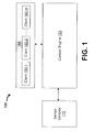
- FIG. 1 illustrates a context aware platform 100, which may handle disparate sensors while conserving resources consumed by the disparate sensors according to one embodiment.
- FIG. 2 illustrates a context engine of the platform 100, which may handle disparate sensors while conserving resources consumed by the disparate sensors according to one embodiment.
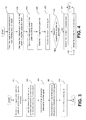
- FIG. 3 is a flow-chart to illustrate the operation of a context provider, which may activate/deactivate disparate sensors to provide a unified approach to couple the disparate sensors to the context aware platform according to one embodiment.
- FIG. 4 is a flow-chart to illustrate the operation of a provider manager, which may cause loading or unloading of the context provider according to one embodiment.
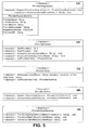
- FIG. 5 illustrates an embodiment of a provider application programming interface (API).
- API application programming interface
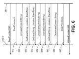
- FIG. 6 illustrates a synchronous mode of communication between the context provider and the provider manager of the context engine according to an embodiment.
- FIG. 7 illustrates an asynchronous mode of communication between the context provider and the provider manager of the context engine according to an embodiment.
- FIG. 8 is a computer system, which may support context awareness while handling sensors according to one embodiment.
- references in the specification to "one embodiment”, “an embodiment”, “an example embodiment”, indicate that the embodiment described may include a particular feature, structure, or characteristic, but every embodiment may not necessarily include the particular feature, structure, or characteristic. Moreover, such phrases are not necessarily referring to the same embodiment. Further, when a particular feature, structure, or characteristic is described in connection with an embodiment, it is submitted that it is within the knowledge of one skilled in the art to affect such feature, structure, or characteristic in connection with other embodiments whether or not explicitly described.
- Embodiments of the invention may be implemented in hardware, firmware, software, or any combination thereof. Embodiments of the invention may also be implemented as instructions stored on a machine-readable medium, which may be read and executed by one or more processors.
- a machine-readable medium may include any mechanism for storing or transmitting information in a form readable by a machine (e.g., a computing device).
- a machine-readable medium may include read only memory (ROM); random access memory (RAM); magnetic disk storage media; optical storage media; flash memory devices; electrical, optical, acoustical or other similar signals.
- FIG. 1 An embodiment of a context aware platform 100, which may handle disparate sensors while conserving resources consumed by the disparate sensors is illustrated in FIG. 1 .
- the context aware platform 100 may comprise a sensor complex 110, a context engine 150, and clients 180.
- the clients 180 may include one or more client entities such as client 180-1 to 180-N.
- the client entities 180-1 to 180-N may include user-level applications, operating system, platform utilities, and tools.
- the clients 180 may arrive at decisions and actions to be performed using contextual information received from the context engine 150.
- the clients 180 may receive the contextual information from the context engine 150 either synchronously or asynchronously.
- the clients 180 may customize the context-processing performed by the context engine 150.
- the sensor complex 110 may comprise an array of disparate sensors, which may include physical and logical sensors.
- the sensors may provide data from which contextual information may be generated.
- the sensors may be hardware components embedded into the context aware platform 100 or coupled to the context aware platform 100 using components such as wired/wireless networks.
- the sensor complex 110 may be coupled to the context engine 150.
- the sensors may generate data based on the sensing of the parameters such as battery charge, active radio, location, humidity, blood pressure and activity level of the user of the context aware platform 100, memory and processor usage and such other parameters.
- the sensors of the sensor complex 110 may be activated and/or deactivated dynamically to provide unified way for the context aware platform 100 to request and receive context information from the sensors and also to conserve the resources consumed by the sensors.
- the context engine 150 may dynamically activate and deactivate the sensors of the sensor complex 110 from the context aware platform 100.
- the context engine 150 may generate hint signals using the information, which may include indicators to the use of sensors by the clients 180.
- the context engine 150 may also generate hint signals based on the information, which may include indicators to the use of sensors by the context engine 150.
- the context engine 150 may activate one or more sensors of the sensor complex 110 based on the hint signal.
- the context engine 150 may also use the hint signal to deactivate one or more sensors coupled to the context aware platform 100.
- activating and/or deactivating of sensors based on the hint signal may provide a unified approach to couple the sensors to the context aware platform 100.
- the context engine 150 may track an elapsed time period for which a sensor may not be in use and if the elapsed time period is more than a first idle threshold value, the context engine 150 may deactivate the sensor, which may conserve resources.
- the context engine 150 may also predict a future time point at which a sensor may be used and if the future time point is greater than a second idle threshold value, the context engine 150 may deactivate the sensor, which may conserve resources consumed by the sensors.
- the hint signal may be generated in direct response to a request from a client 180 for sensor data of one or more of the sensors 210.
- the direct repsonse may include reference counting such that while at least the client 180-1 uses the sensor 210-A, the sensor 210-A may be activated and while the last client 180-K, for example, completes using the sensor 210-A, the sensor 210-A may be deactivated.
- the context engine 150 may use additional heuristics, or inferencing, or historical trend analysis to determine time points at which the sensors 210 may be activated or deactivated. In yet other embodiment, the context engine 150, independent of any client activity, may use other mechansims to anticipate the best use of sensors 210 to activate or deactivate each of the sensors 210.
- the context engine 150 may support unified approach to activate and/or deactivate sensors, while causing conservation of resources consumed by the sensors is illustrated in FIG. 2 .
- the context engine 150 may comprise a client interface 220, a control logic 240, one or more context providers 250-1 to 250-K, and a provider manager 280.
- the client interface 220 may couple the clients 180 to the context engine 150. In one embodiment, the client interface 220 may receive contextual information from the provider manager 280 after receiving an indication from the control logic 240. In one embodiment, the client interface 220 may transfer the contextual information to one or more of the appropriate clients 180-1 to 180-m based on control values provided by the control logic 240. In one embodiment, the client interface 220 may also transfer control data generated by the clients 180 to the context engine 150. In one embodiment, the control data may include rules, indications of sensor usage, and such other similar data.
- control logic 240 may receive an indication from the provider manager 280 and may cause the contextual information to be transferred from the provider manager 280 to the client interface 220. In one embodiment, the control logic 240 may generate the control values based on the inputs received from the provider manager 280. In one embodiment, the control logic 240 may provide control values to the client interface 220.
- the provider manager 280 may load and/or unload the context providers 250-1 to 250-K based on the preferred activity levels of the sensors 210 or predicted activity levels of the sensors 210. In one embodiment, the provider manager 280 may program the load field of the hint signal to a specific logic value, for example, '1' to load and '0' to unload the context provider 250-1. In one embodiment, the provider manager 280 may also program the activity level fields of the hint signal with a first logic level or a second logic value to either activate or deactivate the sensors 210-A and 210-B coupled to the context provider 250.
- the provider manager 280 may support provider application program interface (API) to communicate with the context providers 250-1 to 250-K
- the provider API may enable the provider manager 280 to support activities such as initialization, registration, loading, getting contextual information, unloading, un-installation of the context providers 250-1 to 250-K.
- the provider manager 280 may support activities such as installation, registration and un-installation of the context providers 250-1 to 250-K even while the control engine 150 may be in an inactive state.
- the provider manager 280 may provide hint signals to the context providers 250-1 to 250-K using provider APIs. In one embodiment, the provider manager 280 may start the context providers 250-1 to 250-K before getting the contextual information from the context providers 250-1 to 250-K using the provider API. In one embodiment, the provider manager 280 may get the contextual information from the context provider 250-1 to 250-K synchronously or asynchronously. In one embodiment, the provider manager 280 may provide the contextual information to the client interface 220 in response to receiving a control signal from the control logic 240. In one embodiment, the provider manager 280 may provide indications to the control logic 240 that may enable the control logic 240 to cause the contextual information to be transferred to an appropriate client 180-1 to 180-m.
- the context provider 250-1 may support sensors 210-A and 210-B
- the context provider 250-2 may support sensors 210-C and 210-D
- the context provider 250-K may support sensor 210-N.
- the context providers 250-1 to 250-K may couple the sensors 210-A to 210-N to the context engine 150.
- the operation of the context provider 250-1 to activate and/or deactivate the sensors 210-A and 210-B is described below.
- the other context providers 250-2 to 250-K may operate in a similar mode to activate and/or deactivate the sensors 210-C to 210-N.
- the context provider 250-1 may support protocols, interfaces, and signaling mechanism used by the sensors 210-A and 210-B.
- the context provider 250-1 may also support a common-data access and control protocol, which may be provided in the form of a provider API (application program interface).
- the context provider 250-1 may be loaded if the load/unload field value of the hint signal equals a specific value (e.g., logic 1). In one embodiment, the loaded context provider 250-1 may retrieve the activity level field for the sensors 210-A and 210-B coupled to the context provider 250-1. In one embodiment, the context provider 250-1 may activate the sensor 210-A if the activity level field for 210-A of the hint signal represents a first logic level (e.g., 1) and may deactivate the sensor 210-B if the activity level field for 210-B of the hint signal represents a second logic level (e.g., 0).
- a first logic level e.g. 1
- the context provider 250-1 may activate the sensor 210-B if the activity level field for 210-B of the hint signal represents a second logic level (e.g., 0).
- the context provider 250-1 may activate the sensor 210-A and 210-B, or deactivate the sensors 210-A and 210-B, or activate the sensor 210-A and deactivate the sensor 210-B, or deactivate the sensor 210-A and activate the sensor 210-B.
- An embodiment of the provider API used for communication between the context providers 250-1 to 250-K and the provider manager 280 is described below.
- FIG. 3 An embodiment of an operation of the context provider 250-1, which may activate/deactivate disparate sensors to provide a unified approach to couple the disparate sensors to the context aware platform 100 is illustrated in FIG. 3 .
- the context provider 250-1 may receive a hint signal, which may indicate the preferred activity level of the disparate sensors.
- the hint signal may be received from the provider manager 280.
- the hint signal may indicate that the sensor 210-A may be activated and the sensor 210-B may be deactivated, for example.
- the context provider 250-1 may identify the sensors (first set) that may be activated and sensors (second set) that may be de-activated. In one embodiment, the context provider 250-1 may identify that the sensor 210-A (first set) may be activated and the sensor 210-B (second set) may be de-activated.
- the context provider 250-1 may activate the first set (sensor 210-A). In one embodiment, the context provider 250-1 may send a signal to the sensor 210-A to activate the sensor 210-A.
- the context provider 250-1 may deactivate the second set of sensors (sensor 210-B). In one embodiment, the context provider 250-1 may send a signal to the sensor 210-B to deactivate the sensor 210-B.
- the context provider 250-1 may send a status-update signal to the provider manager 280.
- FIG. 4 An embodiment of an operation of the provider manager 280, which may communicate with the context provider 250-1 to provide a unified approach to handle disparate sensors while conserving resources consumed by the disparate sensors 210 is illustrated in FIG. 4
- the provider manager 280 may track the usage levels of the sensors based on the inputs provided by the clients 180.
- the usage levels of the sensors may indicate that the client 180-2 may use the sensor 210-A within a time period X.
- the usage levels of the sensors provided by the client 180-m may indicate that the sensor 210-B may not be used for next 'Y' time units.
- the provider manager 280 may determine the preferred activity level for the sensors 210-A and 210-B using the usage levels of the sensors tracked using the inputs provided by the clients 180. In one embodiment, the provider manager 280 may determine that the preferred activity level for the sensor 210-A may be equal to 'activate' (first logic level) and that of the sensor 210-B may equal to 'deactivate' (second logic level).
- the provider manager 280 may generate a hint signal based on the activity levels.
- the provider manager 280 may send the hint signal to the context provider 250-1 using the provider API.
- the provider manager 280 may receive a status-update signal after sending the hint signal.
- the provider manager 280 may check if all the sensors coupled to the context provider are deactivated. In one embodiment, the provider manager 280 may check if the sensors 210-A and 210-B coupled to the context provider 250-1 are deactivated and control passes to block 480 if the sensors (210-A and 210-B) coupled to the context provider 250-1 are not deactivated and control passes to block 490 otherwise.
- the provider manager 280 may maintain the loaded state of the context provider 250-1 as at least one sensor 210-A coupled to the context provider 250-1 is in activate state.
- the provider manager 280 may unload the context provider 250-1 if the sensors 210-A and 210-B coupled to the context provider 250-1 are deactivated.
- the provider manager 280 may perform speculative loading or unloading of the context providers 250 based on usage patterns of the sensors 210 by the client entities 180-1 to 180-m. In one embodiment, the provider manager 280 may speculate the usage of the sensors 210 by the clients 180 and may load the context provider 250 that may couple such sensors to the context aware platform 100. In other embodiments, the provider manager 280 may continue to maintain the context provider 250 in a loaded state to avoid, for example, frequent loading and unloading of the context provider 250.
- the prior usage patterns may include probability values which indicate a probability of use of the plurality of sensors by the client entities, wherein the usage patterns may include frequency values which indicate the frequency of use of the plurality of sensors by the client entities.
- the provider API comprises a registration interface IProviderRegistration 510 and the context provider 250-1 to 250-K may register with the context aware platform 100 using the IProviderRegistration interface 510.
- the provider manager 280 may use the context providers 250-1 to 250-K after the context providers 250-1 to 250-K get installed and registered with the context aware platform 100.
- the installation process may include copying the files onto a memory such as the hard drive and y setting any configuration settings that may be specific to the sensors 210 that the context providers 250 support. After the installation, the provider manager 280 may allow the context providers 250 to register with the context aware platform 100.
- the RegisterProvider() may be used to indicate when the context provider 250 is installed and ready for use.
- the RemoveProvider() may be used to remove the context provider 250 from the context aware platform 100, which may occur during the uninstalling process (i.e. before the files are deleted from the system).
- the IProviderRegister may be used even while the context engine 150 may not be actively running.
- the ProviderRegistationInfo interface may be used to describe the context providers 250, which may be registered and the XMLDoc that may be passed in as the RegistrationDetails parameter may describe all the context identifiers supported by the context providers 250.
- the provider manager 280 may use the IProviderControl interface 520 to complete the initialization process and to "activate" individual identifiers supported by the context providers 250 in addition to getting access to the IProviderData interface. In one embodiment, the provider manager 280 may use StartProvider() and StopProvider() interfaces to complete initialization, which may not be done while the context provider 250 is initally initialized. In one embodiment, the provider manager 280 may call the IProviderRegistration interface 510 before using the context provider 250 and the IProviderControl interface 520 before unloading the context provider 250.
- the provider manager 280 may use ActivateContext() to indicate to the context provider 250 the identifiers that may be used by the context aware platform 100.
- the context provider 250 may power ON the platform resources including power to conserve the resources consumed by the sensors 210.
- the context providers 250 power ON some of the hardware resources and load some of the software resources to provide information for the hardware and software resources that are activated.
- after deactivation of the context providers 250 may turn OFF the sensors 210 and unload the unused hardware and software resources.
- the provider manager 280 may enable the context provider 250 to activate and/or deactivate the individual identifiers multiple times during the life-span of a single instance of the context providers 250.
- the GetProviderData() may return a reference to the IProviderData interface 530 which may be used to get the contextual information from the context provider 250.
- the provider manager 280 may use the IProviderData interface 530 to get the contextual information "on demand" by calling the GetData() method. In one embodiment, the provider manager 280 may use GetData() method frequently and the GetData() may be optimized to run quickly. In one embodiment, the IProviderData interface 530 may be used to get a reference to the IProviderNotifier interface 540, by calling GetProviderNotifier(), for asynchronous notification.
- the provider manager 280 may use IProviderNotifier interface 540 to register for proactive notifications of data changes that may avoid the need to poll the context provider 250 for changes.
- the provider manager 280 may instantiate an object that implements IProviderDataObserver such that a pointer to IProviderDataObserver interface may be passed in to RegisterObserver() and RemoveObserver() to start the event notifications and stop notifications.
- the context providers 250 may support multiple observers.
- the observer object may be notified by the context provider 250 of the data changes uisng the IProviderDataObserver interface 550.
- the context provider 250 may call the EventContextUpdateAvailable() to inform the provider manager 280 of the change in the data associated with aContextName after the previous report provided by the context provider 250.
- the control logic 240 may place the data into a queue and return control to the context provider 250.
- the queue may be serviced by an internal thread by calling IProviderData::GetData() to get the latest data associated with aContextName and to put the new context item into a context store.
- the context provider 250 may use EventIdentifierOnline() and EventIdentifierOffline() objects to notify the provider manager 280 if an identifier supported by the context provider 250 is temporarily unavailable.
- the identifier may become unavailable for a variety of reasons.
- the sensor 210 may be connected to the platform 100 using a serial or universal serial bus cable and a user may decouple the sensor 210 from the platform 100,
- the context provider 250 may report out such an event as EventIdentiferOffline().
- the context provider 250 may also use EventIdentifierOnline() to report out an event of reconnection of the sensor 210.
- Decoupling and coupling of the sensor 210 may be caused, for example, due to loss and establishment of wireless connectivity that may trigger an EventIdentifierOffline() and EventIdentifierOnline(). While the identifier in the context provider 250 is in the Offline state, the provider manager 280 may not call the GetData() method to get contextual information.
- the LoadProvider() 601 and UnloadProvider() 699 may be implemented by a operating system supported by the context aware platform 100.
- the provider manager 280 may call the LoadPovider() 601 to load a specific context provider 250 and may call UnloadProvider() 699 to unload the earlier loaded context provider 250.
- the context providers 250 may be loaded and unloaded and reloaded as determined by the provider manager 280.
- the LoadProvider() 601 and UnloadProvider() 699 are shown outside the line representing 250 to indicate that the LoadProvider() 601 and UnloadProvider() 699 methods are not a part of the provider API.
- the provider manager 280 may call StartProvider() method 610 to allow the context provider 250-1 to perform initialization that may not be performed during initial initialization phase.
- the provider manager 280 may perform ActivateContext(string) method 620, which may indicate to the context provider 250-1 the identifiers that may be used by the context aware platform 100.
- the provider manager 280 may call GetData(String, Location, DateTime) multiple times to get the contextual information from the context provider 250-1.
- the GetData() may return with contextual information (of string type), location details, and date and time details.
- the multiple calls to the GetData() method may be represented by the calls 630, 650 and 660.
- the provider manager 280 may call DeactivateContext(String) 652 to deactivate the sensors 210 and may call ActivateContext(String) 658 to activate the sensors 210.
- the provider manager 280 may then perform the DeactivateContext(string) method 680 to deactivate the identifiers, which may not be used by the context aware platform 100. In one embodiment, the provider manager 280 may then call StopProvider() 690 before unloading the context provider 250-1.
- the IProviderControl interface 520 may comprise the methods StartProvider() 610, ActivateContext() 620, GetData() 630, 650, and 660, DeactivateContext() 680, and the StopProvider() 690.
- FIG. 7 An embodiment of an asynchronous mechanism enabling communication between the context provider 250-1 and the provider manager 280 is illustrated in FIG. 7 .
- the LoadProvider() 701 and UnloadProvider() 799 may be implemented by a operating system supported by the context aware platform 100.
- the provider manager 280 may call the LoadPovider() 701-1 and 701-2 to load a specific context provider 250 and may call UnloadProvider() 799-1 and 799-2 to unload the earlier loaded context provider 250.
- the context providers 250 may be loaded and unloaded and reloaded as determined by the provider manager 280.
- the LoadProvider() 701-1 and 701-2 and UnloadProvider() 799-1 and 799-2 are shown outside the line representing 250 to indicate that the LoadProvider() 701-1 and 701-2 and UnloadProvider() 799-1 and 799-2 methods are not a part of the provider API.
- the provider manager 280 may call StartProvider() method 705 to allow the context provider 250-1 to perform initialization that may not be performed during initial initialization phase.
- the provider manager 280 may perform ActivateContext(stringA) method 710-1 and ActivateContext(stringA) method 710-2, which may indicate to the context provider 250-1 the identifiers that may be used by the context aware platform 100.
- the provider manager 280 may call GetProviderNotifier(String) 720, which may be used for asynchronous data notification.
- the provider manager 280 may use RegisterObserver(ProviderDataObserver*) method 725 so that a pointer to method 725 may be passed in to RegisterObserver() to start the event notifications.
- the context provider 250-1 may call the EventContextUpdateAvailable(StringA) 730-1 and EventContextUpdateAvailable(StringB) 730-2 to inform the provider manager 280 of the change in the data associated with aContextName after the previous report provided by the context provider 250-1.
- the context provider 250-1 may call the EventContextUpdateAvailable(StringA) 730-1 and EventContextUpdateAvailable(StringB) 730-2 multiple times and Fig. 7 depicts that the context provider 250-1 calls the EventContextUpdateAvailable(String) thrice 730-1 and 730-2 and 759.
- the provider manager 280 may call GetData(StringB, Location, DateTime) 750-1 and GetData(StringA, Location, DateTime) 750-2 multiple times to get the contextual information from the context provider 250-1.
- the GetData() may return with contextual information (of string type), location details, and date and time details.
- the multiple calls to the GetData() method may be represented by the calls 750-1, 750-2 and 760.
- the provider manager 280 may use RemoveObserver(IProviderObserver*) 752 such that a pointer to IProviderDataObserver interface may be passed in to RemoveObserver() to stop notifications.
- the provider manager 280 may then perform the DeactivateContext(stringA) method 753-1 and DeactivateContext(stringA) method 753-2 to deactivate the identifiers, which may not be used by the context aware platform 100.
- the provider manager 280 may then call StopProvider() 754 before unloading the context provider 250-1 using UnloadProvider() 799-1.
- the ActivateContext(StringA) 710-1 and ActivateContext(StringB) 710-2 may, respectively, activate the sensors 210-A and 210-B, for example.
- the DeactivateContext(StringA) 753-1 and DeactivateContext(StringB) 753-2 may, respectively, deactivate the sensors 210-A and 210-B, for example.
- UnloadProvider() 799-1 and LoadProvider() 701-2 the provider manager 280 and the context provider 250 may not, respectively, call the GetData() and EventContextUpdateAvailable() 730 methods.
- the context provider 250 may be reloaded by performing LoadProvider() 701-2 and the sequence of events such as the StartProvider() 755, ActivateContext(StringA) 756-1, ActivateContext(StringB) 756-2, GetProviderNotifier(StringA) 757, RegisterObserver(IProviderDataObserver*) 758, EventContextUpdateAvailable(StringA) 759, GetData(StringA, Location, DateTime) 760, RemoveObserver(IProviderObserver*) 780, DeactivateContext(StringA) 785-1 and DeactivateContext(StringB) 785-2 and StopProvider() 790 may be called before unloading UnloadProvider() 799-2 the context provider 250-1
- a computer system 800 supporting a context aware platform 100 may comprise a processor 802, which may include a single instruction multiple data (SIMD), reduced instruction set (RISC), and such other similar general purpose processors and a graphics processor unit (GPU) 805.
- the processor 802 may process a sequence of instructions, to provide and execute the codes for the context providers 250, the provider manager 280, and the clients 180, which may be stored in machine readable storage medium 825.
- the sequence of instructions may also be stored in the memory 820 or in any other suitable storage medium.
- the processor 802 that operates the computer system 800 may be one or more processor cores coupled to logic 830.
- the processor 810 may comprise a central processing unit and a memory subsystem.
- the context providers 250 and the provider manager 280 may together provide a unified approach to, dynamically, load and/or unload context providers 250, which may activate and/or deactivate sensors 210 while conserving the resources such as the power, memory space consumed by the sensors 210 and the context providers 250 coupling the sensors 210 to the context aware platform 100 in a loaded state.
- the logic 830 could be chipset logic in one embodiment.
- the logic 830 is coupled to the memory 820, which can be any kind of storage, including optical, magnetic, or semiconductor storage.
- the I/O devices 860 may allow the computer system 800 to interface with the devices such as the sensors 210-A to 210-N.
Landscapes
- Engineering & Computer Science (AREA)
- Business, Economics & Management (AREA)
- Strategic Management (AREA)
- Human Resources & Organizations (AREA)
- Economics (AREA)
- Signal Processing (AREA)
- Quality & Reliability (AREA)
- Computer Networks & Wireless Communication (AREA)
- Development Economics (AREA)
- Medical Informatics (AREA)
- Game Theory and Decision Science (AREA)
- General Health & Medical Sciences (AREA)
- Computing Systems (AREA)
- Entrepreneurship & Innovation (AREA)
- Marketing (AREA)
- Operations Research (AREA)
- Health & Medical Sciences (AREA)
- Tourism & Hospitality (AREA)
- Physics & Mathematics (AREA)
- General Business, Economics & Management (AREA)
- General Physics & Mathematics (AREA)
- Theoretical Computer Science (AREA)
- Stored Programmes (AREA)
- Telephonic Communication Services (AREA)
- Computer And Data Communications (AREA)
- Mobile Radio Communication Systems (AREA)
Abstract
Description
- A context aware platform may understand itself, its user, and its surroundings and may adapt to the behavior, make decisions or act on behalf of the user without receiving explicit user inputs. The context aware platform may generate context information and based on the context information, the context aware platform may adapt without receiving explicit user inputs. The context information may be generated using the data provided by the sensors. The sensors may generate the data based on the inputs that the sensors sense.
- The type and the disparity of the sensors that are available in the market place are ever increasing. The current context aware platforms lack the ability to handle disparate sensors. Also, the sensors and the associated front-end processing modules may consume significant amount of resources like battery power, network bandwidth, processing cycles, and such other similar resources. The current context aware platforms lack the ability to handle the sensors to conserve such resources.
- The invention described herein is illustrated by way of example and not by way of limitation in the accompanying figures. For simplicity and clarity of illustration, elements illustrated in the figures are not necessarily drawn to scale. For example, the dimensions of some elements may be exaggerated relative to other elements for clarity. Further, where considered appropriate, reference labels have been repeated among the figures to indicate corresponding or analogous elements.
-
FIG. 1 illustrates a contextaware platform 100, which may handle disparate sensors while conserving resources consumed by the disparate sensors according to one embodiment. -
FIG. 2 illustrates a context engine of theplatform 100, which may handle disparate sensors while conserving resources consumed by the disparate sensors according to one embodiment. -
FIG. 3 is a flow-chart to illustrate the operation of a context provider, which may activate/deactivate disparate sensors to provide a unified approach to couple the disparate sensors to the context aware platform according to one embodiment. -
FIG. 4 is a flow-chart to illustrate the operation of a provider manager, which may cause loading or unloading of the context provider according to one embodiment. -
FIG. 5 illustrates an embodiment of a provider application programming interface (API). -
FIG. 6 illustrates a synchronous mode of communication between the context provider and the provider manager of the context engine according to an embodiment. -
FIG. 7 illustrates an asynchronous mode of communication between the context provider and the provider manager of the context engine according to an embodiment. -
FIG. 8 is a computer system, which may support context awareness while handling sensors according to one embodiment. - The following description describes embodiments of a technique to handle sensors in a context aware platform. In the following description, numerous specific details such as logic implementations, resource partitioning, or sharing, or duplication implementations, types and interrelationships of system components, and logic partitioning or integration choices are set forth in order to provide a more thorough understanding of the present invention. It will be appreciated, however, by one skilled in the art that the invention may be practiced without such specific details. In other instances, control structures, gate level circuits, and full software instruction sequences have not been shown in detail in order not to obscure the invention. Those of ordinary skill in the art, with the included descriptions, will be able to implement appropriate functionality without undue experimentation.
- References in the specification to "one embodiment", "an embodiment", "an example embodiment", indicate that the embodiment described may include a particular feature, structure, or characteristic, but every embodiment may not necessarily include the particular feature, structure, or characteristic. Moreover, such phrases are not necessarily referring to the same embodiment. Further, when a particular feature, structure, or characteristic is described in connection with an embodiment, it is submitted that it is within the knowledge of one skilled in the art to affect such feature, structure, or characteristic in connection with other embodiments whether or not explicitly described.
- Embodiments of the invention may be implemented in hardware, firmware, software, or any combination thereof. Embodiments of the invention may also be implemented as instructions stored on a machine-readable medium, which may be read and executed by one or more processors. A machine-readable medium may include any mechanism for storing or transmitting information in a form readable by a machine (e.g., a computing device).
- For example, a machine-readable medium may include read only memory (ROM); random access memory (RAM); magnetic disk storage media; optical storage media; flash memory devices; electrical, optical, acoustical or other similar signals. Further, firmware, software, routines, and instructions may be described herein as performing certain actions. However, it should be appreciated that such descriptions are merely for convenience and that such actions in fact result from computing devices, processors, controllers, and other devices executing the firmware, software, routines, and instructions.
- An embodiment of a context
aware platform 100, which may handle disparate sensors while conserving resources consumed by the disparate sensors is illustrated inFIG. 1 . In one embodiment, the contextaware platform 100 may comprise asensor complex 110, acontext engine 150, andclients 180. - In one embodiment, the
clients 180 may include one or more client entities such as client 180-1 to 180-N. In one embodiment, the client entities 180-1 to 180-N may include user-level applications, operating system, platform utilities, and tools. In one embodiment, theclients 180 may arrive at decisions and actions to be performed using contextual information received from thecontext engine 150. In one embodiment, theclients 180 may receive the contextual information from thecontext engine 150 either synchronously or asynchronously. In one embodiment, theclients 180 may customize the context-processing performed by thecontext engine 150. - In one embodiment, the
sensor complex 110 may comprise an array of disparate sensors, which may include physical and logical sensors. In one embodiment, the sensors may provide data from which contextual information may be generated. In one embodiment, the sensors may be hardware components embedded into the contextaware platform 100 or coupled to the contextaware platform 100 using components such as wired/wireless networks. In one embodiment, thesensor complex 110 may be coupled to thecontext engine 150. In one embodiment, the sensors may generate data based on the sensing of the parameters such as battery charge, active radio, location, humidity, blood pressure and activity level of the user of the contextaware platform 100, memory and processor usage and such other parameters. In one embodiment, the sensors of thesensor complex 110 may be activated and/or deactivated dynamically to provide unified way for the contextaware platform 100 to request and receive context information from the sensors and also to conserve the resources consumed by the sensors. - In one embodiment, the
context engine 150 may dynamically activate and deactivate the sensors of thesensor complex 110 from the contextaware platform 100. In one embodiment, thecontext engine 150 may generate hint signals using the information, which may include indicators to the use of sensors by theclients 180. In one embodiment, thecontext engine 150 may also generate hint signals based on the information, which may include indicators to the use of sensors by thecontext engine 150. In one embodiment, thecontext engine 150 may activate one or more sensors of thesensor complex 110 based on the hint signal. In one embodiment, thecontext engine 150 may also use the hint signal to deactivate one or more sensors coupled to the contextaware platform 100. - In one embodiment, activating and/or deactivating of sensors based on the hint signal may provide a unified approach to couple the sensors to the context
aware platform 100. In one embodiment, thecontext engine 150 may track an elapsed time period for which a sensor may not be in use and if the elapsed time period is more than a first idle threshold value, thecontext engine 150 may deactivate the sensor, which may conserve resources. In one embodiment, thecontext engine 150 may also predict a future time point at which a sensor may be used and if the future time point is greater than a second idle threshold value, thecontext engine 150 may deactivate the sensor, which may conserve resources consumed by the sensors. - In one embodiment, the hint signal may be generated in direct response to a request from a
client 180 for sensor data of one or more of thesensors 210. In one embodiment, the direct repsonse may include reference counting such that while at least the client 180-1 uses the sensor 210-A, the sensor 210-A may be activated and while the last client 180-K, for example, completes using the sensor 210-A, the sensor 210-A may be deactivated. - In other embodiment, in addition to monitoring the usage of each
sensors 210 by theclients 180, thecontext engine 150 may use additional heuristics, or inferencing, or historical trend analysis to determine time points at which thesensors 210 may be activated or deactivated. In yet other embodiment, thecontext engine 150, independent of any client activity, may use other mechansims to anticipate the best use ofsensors 210 to activate or deactivate each of thesensors 210. - An embodiment of the
context engine 150, which may support unified approach to activate and/or deactivate sensors, while causing conservation of resources consumed by the sensors is illustrated inFIG. 2 . In one embodiment, thecontext engine 150 may comprise aclient interface 220, acontrol logic 240, one or more context providers 250-1 to 250-K, and aprovider manager 280. - In one embodiment, the
client interface 220 may couple theclients 180 to thecontext engine 150. In one embodiment, theclient interface 220 may receive contextual information from theprovider manager 280 after receiving an indication from thecontrol logic 240. In one embodiment, theclient interface 220 may transfer the contextual information to one or more of the appropriate clients 180-1 to 180-m based on control values provided by thecontrol logic 240. In one embodiment, theclient interface 220 may also transfer control data generated by theclients 180 to thecontext engine 150. In one embodiment, the control data may include rules, indications of sensor usage, and such other similar data. - In one embodiment, the
control logic 240 may receive an indication from theprovider manager 280 and may cause the contextual information to be transferred from theprovider manager 280 to theclient interface 220. In one embodiment, thecontrol logic 240 may generate the control values based on the inputs received from theprovider manager 280. In one embodiment, thecontrol logic 240 may provide control values to theclient interface 220. - In one embodiment, the
provider manager 280 may load and/or unload the context providers 250-1 to 250-K based on the preferred activity levels of thesensors 210 or predicted activity levels of thesensors 210. In one embodiment, theprovider manager 280 may program the load field of the hint signal to a specific logic value, for example, '1' to load and '0' to unload the context provider 250-1. In one embodiment, theprovider manager 280 may also program the activity level fields of the hint signal with a first logic level or a second logic value to either activate or deactivate the sensors 210-A and 210-B coupled to thecontext provider 250. In one embodiment, theprovider manager 280 may support provider application program interface (API) to communicate with the context providers 250-1 to 250-K In one embodiment, the provider API may enable theprovider manager 280 to support activities such as initialization, registration, loading, getting contextual information, unloading, un-installation of the context providers 250-1 to 250-K. In one embodiment, theprovider manager 280 may support activities such as installation, registration and un-installation of the context providers 250-1 to 250-K even while thecontrol engine 150 may be in an inactive state. - In one embodiment, the
provider manager 280 may provide hint signals to the context providers 250-1 to 250-K using provider APIs. In one embodiment, theprovider manager 280 may start the context providers 250-1 to 250-K before getting the contextual information from the context providers 250-1 to 250-K using the provider API. In one embodiment, theprovider manager 280 may get the contextual information from the context provider 250-1 to 250-K synchronously or asynchronously. In one embodiment, theprovider manager 280 may provide the contextual information to theclient interface 220 in response to receiving a control signal from thecontrol logic 240. In one embodiment, theprovider manager 280 may provide indications to thecontrol logic 240 that may enable thecontrol logic 240 to cause the contextual information to be transferred to an appropriate client 180-1 to 180-m. - In one embodiment, the context provider 250-1 may support sensors 210-A and 210-B, the context provider 250-2 may support sensors 210-C and 210-D, and the context provider 250-K may support sensor 210-N. In one embodiment, the context providers 250-1 to 250-K may couple the sensors 210-A to 210-N to the
context engine 150. In one embodiment, the operation of the context provider 250-1 to activate and/or deactivate the sensors 210-A and 210-B is described below. However, the other context providers 250-2 to 250-K may operate in a similar mode to activate and/or deactivate the sensors 210-C to 210-N. To couple the sensors 210-A and 210-B to thecontext engine 150, in one embodiment, the context provider 250-1 may support protocols, interfaces, and signaling mechanism used by the sensors 210-A and 210-B. In one embodiment, the context provider 250-1 may also support a common-data access and control protocol, which may be provided in the form of a provider API (application program interface). - In one embodiment, the context provider 250-1 may be loaded if the load/unload field value of the hint signal equals a specific value (e.g., logic 1). In one embodiment, the loaded context provider 250-1 may retrieve the activity level field for the sensors 210-A and 210-B coupled to the context provider 250-1. In one embodiment, the context provider 250-1 may activate the sensor 210-A if the activity level field for 210-A of the hint signal represents a first logic level (e.g., 1) and may deactivate the sensor 210-B if the activity level field for 210-B of the hint signal represents a second logic level (e.g., 0). In one embodiment, the context provider 250-1, based on the activity level field of the sensors 210-A and 210-B, may activate the sensor 210-A and 210-B, or deactivate the sensors 210-A and 210-B, or activate the sensor 210-A and deactivate the sensor 210-B, or deactivate the sensor 210-A and activate the sensor 210-B. An embodiment of the provider API used for communication between the context providers 250-1 to 250-K and the
provider manager 280 is described below. - An embodiment of an operation of the context provider 250-1, which may activate/deactivate disparate sensors to provide a unified approach to couple the disparate sensors to the context
aware platform 100 is illustrated inFIG. 3 . - In
block 310, the context provider 250-1 may receive a hint signal, which may indicate the preferred activity level of the disparate sensors. In one embodiment, the hint signal may be received from theprovider manager 280. In one embodiment, the hint signal may indicate that the sensor 210-A may be activated and the sensor 210-B may be deactivated, for example. - In
block 340, the context provider 250-1 may identify the sensors (first set) that may be activated and sensors (second set) that may be de-activated. In one embodiment, the context provider 250-1 may identify that the sensor 210-A (first set) may be activated and the sensor 210-B (second set) may be de-activated. - In
block 360, the context provider 250-1 may activate the first set (sensor 210-A). In one embodiment, the context provider 250-1 may send a signal to the sensor 210-A to activate the sensor 210-A. - In
block 380, the context provider 250-1 may deactivate the second set of sensors (sensor 210-B). In one embodiment, the context provider 250-1 may send a signal to the sensor 210-B to deactivate the sensor 210-B. - In
block 390, the context provider 250-1 may send a status-update signal to theprovider manager 280. - An embodiment of an operation of the
provider manager 280, which may communicate with the context provider 250-1 to provide a unified approach to handle disparate sensors while conserving resources consumed by thedisparate sensors 210 is illustrated inFIG. 4 - In
block 420, theprovider manager 280 may track the usage levels of the sensors based on the inputs provided by theclients 180. In one embodiment, the usage levels of the sensors may indicate that the client 180-2 may use the sensor 210-A within a time period X. Also, the usage levels of the sensors provided by the client 180-m may indicate that the sensor 210-B may not be used for next 'Y' time units. - In
block 430, theprovider manager 280 may determine the preferred activity level for the sensors 210-A and 210-B using the usage levels of the sensors tracked using the inputs provided by theclients 180. In one embodiment, theprovider manager 280 may determine that the preferred activity level for the sensor 210-A may be equal to 'activate' (first logic level) and that of the sensor 210-B may equal to 'deactivate' (second logic level). - In
block 440, theprovider manager 280 may generate a hint signal based on the activity levels. In block 450, theprovider manager 280 may send the hint signal to the context provider 250-1 using the provider API. Inblock 460, theprovider manager 280 may receive a status-update signal after sending the hint signal. - In
block 470, theprovider manager 280 may check if all the sensors coupled to the context provider are deactivated. In one embodiment, theprovider manager 280 may check if the sensors 210-A and 210-B coupled to the context provider 250-1 are deactivated and control passes to block 480 if the sensors (210-A and 210-B) coupled to the context provider 250-1 are not deactivated and control passes to block 490 otherwise. - In
block 480, theprovider manager 280 may maintain the loaded state of the context provider 250-1 as at least one sensor 210-A coupled to the context provider 250-1 is in activate state. - In
block 490, theprovider manager 280 may unload the context provider 250-1 if the sensors 210-A and 210-B coupled to the context provider 250-1 are deactivated. - In other embodiments, the
provider manager 280 may perform speculative loading or unloading of thecontext providers 250 based on usage patterns of thesensors 210 by the client entities 180-1 to 180-m. In one embodiment, theprovider manager 280 may speculate the usage of thesensors 210 by theclients 180 and may load thecontext provider 250 that may couple such sensors to the contextaware platform 100. In other embodiments, theprovider manager 280 may continue to maintain thecontext provider 250 in a loaded state to avoid, for example, frequent loading and unloading of thecontext provider 250. - In one embodiment, the prior usage patterns may include probability values which indicate a probability of use of the plurality of sensors by the client entities, wherein the usage patterns may include frequency values which indicate the frequency of use of the plurality of sensors by the client entities.
- An embodiment of the provider API is illustrated in
FIG. 5 . In one embodiment, the provider API comprises aregistration interface IProviderRegistration 510 and the context provider 250-1 to 250-K may register with the contextaware platform 100 using theIProviderRegistration interface 510. - In one embodiment, the
provider manager 280 may use the context providers 250-1 to 250-K after the context providers 250-1 to 250-K get installed and registered with the contextaware platform 100. In one embodiment, the installation process may include copying the files onto a memory such as the hard drive and y setting any configuration settings that may be specific to thesensors 210 that thecontext providers 250 support. After the installation, theprovider manager 280 may allow thecontext providers 250 to register with the contextaware platform 100. - In one embodiment, the RegisterProvider() may be used to indicate when the
context provider 250 is installed and ready for use. In one embodiment, the RemoveProvider() may be used to remove thecontext provider 250 from the contextaware platform 100, which may occur during the uninstalling process (i.e. before the files are deleted from the system). In one embodiment, the IProviderRegister may be used even while thecontext engine 150 may not be actively running. In one embodiment, the ProviderRegistationInfo interface may be used to describe thecontext providers 250, which may be registered and the XMLDoc that may be passed in as the RegistrationDetails parameter may describe all the context identifiers supported by thecontext providers 250. - In one embodiment, the
provider manager 280 may use theIProviderControl interface 520 to complete the initialization process and to "activate" individual identifiers supported by thecontext providers 250 in addition to getting access to the IProviderData interface. In one embodiment, theprovider manager 280 may use StartProvider() and StopProvider() interfaces to complete initialization, which may not be done while thecontext provider 250 is initally initialized. In one embodiment, theprovider manager 280 may call theIProviderRegistration interface 510 before using thecontext provider 250 and theIProviderControl interface 520 before unloading thecontext provider 250. - In one embodiment, the
provider manager 280 may use ActivateContext() to indicate to thecontext provider 250 the identifiers that may be used by the contextaware platform 100. In one embodiment, thecontext provider 250 may power ON the platform resources including power to conserve the resources consumed by thesensors 210. In one embodiment, thecontext providers 250 power ON some of the hardware resources and load some of the software resources to provide information for the hardware and software resources that are activated. In one embodiment, after deactivation of thecontext providers 250 may turn OFF thesensors 210 and unload the unused hardware and software resources. In one embodiment, theprovider manager 280 may enable thecontext provider 250 to activate and/or deactivate the individual identifiers multiple times during the life-span of a single instance of thecontext providers 250. In one embodiment, the GetProviderData() may return a reference to theIProviderData interface 530 which may be used to get the contextual information from thecontext provider 250. - In one embodiment, the
provider manager 280 may use theIProviderData interface 530 to get the contextual information "on demand" by calling the GetData() method. In one embodiment, theprovider manager 280 may use GetData() method frequently and the GetData() may be optimized to run quickly. In one embodiment, theIProviderData interface 530 may be used to get a reference to theIProviderNotifier interface 540, by calling GetProviderNotifier(), for asynchronous notification. - In one embodiment, the
provider manager 280 may useIProviderNotifier interface 540 to register for proactive notifications of data changes that may avoid the need to poll thecontext provider 250 for changes. In one embodiment, theprovider manager 280 may instantiate an object that implements IProviderDataObserver such that a pointer to IProviderDataObserver interface may be passed in to RegisterObserver() and RemoveObserver() to start the event notifications and stop notifications. In one embodiment, thecontext providers 250 may support multiple observers. - In one embodiment, while registering, if the IProviderNotifier is used the observer object may be notified by the
context provider 250 of the data changes uisng theIProviderDataObserver interface 550. In one embodiment, thecontext provider 250 may call the EventContextUpdateAvailable() to inform theprovider manager 280 of the change in the data associated with aContextName after the previous report provided by thecontext provider 250. In one embodiment, thecontrol logic 240 may place the data into a queue and return control to thecontext provider 250. In one embodiment, the queue may be serviced by an internal thread by calling IProviderData::GetData() to get the latest data associated with aContextName and to put the new context item into a context store. - In one embodiment, the
context provider 250 may use EventIdentifierOnline() and EventIdentifierOffline() objects to notify theprovider manager 280 if an identifier supported by thecontext provider 250 is temporarily unavailable. In one embodiment, the identifier may become unavailable for a variety of reasons. For example, thesensor 210 may be connected to theplatform 100 using a serial or universal serial bus cable and a user may decouple thesensor 210 from theplatform 100, In one embodiment, thecontext provider 250 may report out such an event as EventIdentiferOffline(). In one embodiment, thecontext provider 250 may also use EventIdentifierOnline() to report out an event of reconnection of thesensor 210. Decoupling and coupling of thesensor 210 may be caused, for example, due to loss and establishment of wireless connectivity that may trigger an EventIdentifierOffline() and EventIdentifierOnline(). While the identifier in thecontext provider 250 is in the Offline state, theprovider manager 280 may not call the GetData() method to get contextual information. - An embodiment of a synchronous mechanism enabling communication between the context provider 250-1 and the
provider manager 280 is illustrated inFIG. 6 . In one embodiment, the LoadProvider() 601 and UnloadProvider() 699 may be implemented by a operating system supported by the contextaware platform 100. In one embodiment, theprovider manager 280 may call the LoadPovider() 601 to load aspecific context provider 250 and may call UnloadProvider() 699 to unload the earlierloaded context provider 250. In one embodiment, thecontext providers 250 may be loaded and unloaded and reloaded as determined by theprovider manager 280. In one embodiment, the LoadProvider() 601 and UnloadProvider() 699 are shown outside the line representing 250 to indicate that the LoadProvider() 601 and UnloadProvider() 699 methods are not a part of the provider API. - In one embodiment, the
provider manager 280 may call StartProvider()method 610 to allow the context provider 250-1 to perform initialization that may not be performed during initial initialization phase. In one embodiment, theprovider manager 280 may perform ActivateContext(string)method 620, which may indicate to the context provider 250-1 the identifiers that may be used by the contextaware platform 100. In one embodiment, theprovider manager 280 may call GetData(String, Location, DateTime) multiple times to get the contextual information from the context provider 250-1. In one embodiment, the GetData() may return with contextual information (of string type), location details, and date and time details. In one embodiment, the multiple calls to the GetData() method may be represented by thecalls method provider manager 280 may call DeactivateContext(String) 652 to deactivate thesensors 210 and may call ActivateContext(String) 658 to activate thesensors 210. - In one embodiment, the
provider manager 280 may then perform the DeactivateContext(string)method 680 to deactivate the identifiers, which may not be used by the contextaware platform 100. In one embodiment, theprovider manager 280 may then call StopProvider() 690 before unloading the context provider 250-1. In one embodiment, theIProviderControl interface 520 may comprise the methods StartProvider() 610, ActivateContext() 620, GetData() 630, 650, and 660, DeactivateContext() 680, and the StopProvider() 690. - An embodiment of an asynchronous mechanism enabling communication between the context provider 250-1 and the
provider manager 280 is illustrated inFIG. 7 . In one embodiment, the LoadProvider() 701 and UnloadProvider() 799 may be implemented by a operating system supported by the contextaware platform 100. In one embodiment, theprovider manager 280 may call the LoadPovider() 701-1 and 701-2 to load aspecific context provider 250 and may call UnloadProvider() 799-1 and 799-2 to unload the earlierloaded context provider 250. In one embodiment, thecontext providers 250 may be loaded and unloaded and reloaded as determined by theprovider manager 280. In one embodiment, the LoadProvider() 701-1 and 701-2 and UnloadProvider() 799-1 and 799-2 are shown outside the line representing 250 to indicate that the LoadProvider() 701-1 and 701-2 and UnloadProvider() 799-1 and 799-2 methods are not a part of the provider API. - In one embodiment, the
provider manager 280 may call StartProvider()method 705 to allow the context provider 250-1 to perform initialization that may not be performed during initial initialization phase. In one embodiment, theprovider manager 280 may perform ActivateContext(stringA) method 710-1 and ActivateContext(stringA) method 710-2, which may indicate to the context provider 250-1 the identifiers that may be used by the contextaware platform 100. In one embodiment, theprovider manager 280 may call GetProviderNotifier(String) 720, which may be used for asynchronous data notification. In one embodiment, theprovider manager 280 may use RegisterObserver(ProviderDataObserver*)method 725 so that a pointer tomethod 725 may be passed in to RegisterObserver() to start the event notifications. - In one embodiment, the context provider 250-1 may call the EventContextUpdateAvailable(StringA) 730-1 and EventContextUpdateAvailable(StringB) 730-2 to inform the
provider manager 280 of the change in the data associated with aContextName after the previous report provided by the context provider 250-1. In one embodiment, the context provider 250-1 may call the EventContextUpdateAvailable(StringA) 730-1 and EventContextUpdateAvailable(StringB) 730-2 multiple times andFig. 7 depicts that the context provider 250-1 calls the EventContextUpdateAvailable(String) thrice 730-1 and 730-2 and 759. - In one embodiment, the
provider manager 280 may call GetData(StringB, Location, DateTime) 750-1 and GetData(StringA, Location, DateTime) 750-2 multiple times to get the contextual information from the context provider 250-1. In one embodiment, the GetData() may return with contextual information (of string type), location details, and date and time details. In one embodiment, the multiple calls to the GetData() method may be represented by the calls 750-1, 750-2 and 760. - In one embodiment, the
provider manager 280 may use RemoveObserver(IProviderObserver*) 752 such that a pointer to IProviderDataObserver interface may be passed in to RemoveObserver() to stop notifications. In one embodiment, theprovider manager 280 may then perform the DeactivateContext(stringA) method 753-1 and DeactivateContext(stringA) method 753-2 to deactivate the identifiers, which may not be used by the contextaware platform 100. In one embodiment, theprovider manager 280 may then call StopProvider() 754 before unloading the context provider 250-1 using UnloadProvider() 799-1. In one embodiment, the ActivateContext(StringA) 710-1 and ActivateContext(StringB) 710-2 may, respectively, activate the sensors 210-A and 210-B, for example. In one embodiment, the In one embodiment, the DeactivateContext(StringA) 753-1 and DeactivateContext(StringB) 753-2 may, respectively, deactivate the sensors 210-A and 210-B, for example. - In between UnloadProvider() 799-1 and LoadProvider() 701-2, the
provider manager 280 and thecontext provider 250 may not, respectively, call the GetData() and EventContextUpdateAvailable() 730 methods. In one embodiment, after thecontext provider 250 may be reloaded by performing LoadProvider() 701-2 and the sequence of events such as the StartProvider() 755, ActivateContext(StringA) 756-1, ActivateContext(StringB) 756-2, GetProviderNotifier(StringA) 757, RegisterObserver(IProviderDataObserver*) 758, EventContextUpdateAvailable(StringA) 759, GetData(StringA, Location, DateTime) 760, RemoveObserver(IProviderObserver*) 780, DeactivateContext(StringA) 785-1 and DeactivateContext(StringB) 785-2 and StopProvider() 790 may be called before unloading UnloadProvider() 799-2 the context provider 250-1. - Referring to
FIG. 8 , acomputer system 800 supporting a contextaware platform 100 may comprise aprocessor 802, which may include a single instruction multiple data (SIMD), reduced instruction set (RISC), and such other similar general purpose processors and a graphics processor unit (GPU) 805. Theprocessor 802, in one embodiment, may process a sequence of instructions, to provide and execute the codes for thecontext providers 250, theprovider manager 280, and theclients 180, which may be stored in machine readable storage medium 825. However, the sequence of instructions may also be stored in thememory 820 or in any other suitable storage medium. - The
processor 802 that operates thecomputer system 800 may be one or more processor cores coupled tologic 830. In one embodiment, the processor 810 may comprise a central processing unit and a memory subsystem. In one embodiment, thecontext providers 250 and theprovider manager 280 may together provide a unified approach to, dynamically, load and/or unloadcontext providers 250, which may activate and/or deactivatesensors 210 while conserving the resources such as the power, memory space consumed by thesensors 210 and thecontext providers 250 coupling thesensors 210 to the contextaware platform 100 in a loaded state. - The
logic 830, for example, could be chipset logic in one embodiment. Thelogic 830 is coupled to thememory 820, which can be any kind of storage, including optical, magnetic, or semiconductor storage. The I/O devices 860 may allow thecomputer system 800 to interface with the devices such as the sensors 210-A to 210-N. - Certain features of the invention have been described with reference to example embodiments. However, the description is not intended to be construed in a limiting sense. Various modifications of the example embodiments, as well as other embodiments of the invention, which are apparent to persons skilled in the art to which the invention pertains are deemed to lie within the spirit and scope of the invention.
Claims (15)
- A method to handle a plurality of sensors in a context aware platform comprising:providing an application programming interface to enable communication between a provider manager and a plurality of context providers,generating a hint signal based on predicted usage levels of the plurality of sensors, wherein the hint signal is to specify preferred activity level of the plurality of sensors,loading a context provider of the plurality of context providers if a first value is stored in a load field of the hint signal, andunloading the context provider if a second value is stored in the load field of the hint signal.
- The method of claim 1 including activating a first set of sensors coupled to the context provider if the preferred activity level for the first set of sensors is set to an activate state in the hint signal, wherein the plurality of sensors include the first set of sensors.
- The method of claim 2 including deactivating a second set of sensors coupled to the context provider if the preferred activity level for the second set of sensors is set to deactivate state in the hint signal, wherein plurality of sensors include the second set of sensors, and
unloading the context provider if the preferred activity level of the first set of sensors and the second set of sensors is set to deactivate a state in the hint signal. - The method of claim 2 further including getting contextual information from the first set of sensors using the application programming interface, and
transferring the contextual information of a sensor of the first set of sensors to a first client of the client entities, wherein the sensor is logically coupled to the first client. - The method of claim 1 further comprises determining the predicted usage levels for the first and the second set of sensors by tracking usage patterns of first and the second set of sensors by the client entities.
- The method of claim 5 further comprises activating and preserving the state of sensors already activated, speculatively, based on the usage patterns, wherein the usage patterns include probability values indicating probability of use of the plurality of sensors by the client entities and frequency values indicating the frequency of use of the plurality of sensors by the client entities.
- A system to handle sensors in a context aware platform comprising:a context engine including a provider manager coupled to a plurality of context providers, wherein the provider manager is to provide an application programming interface to enable communication between the provider manager and the plurality of context providers,wherein the provider manager is to generate hint signal based on predicted usage levels of the sensors, wherein the hint signal is to specify preferred activity level of the sensors,
wherein the provider manager is to load a context provider of the plurality of context providers if a first value is stored in a load field of the hint signal,
wherein the provider manager is to unload the context provider if a second value is stored in the load field of the hint signal, and
wherein a first set and a second set of the sensors is coupled to the context provider. - The system of claim 7, wherein the context provider is to activate the first set of sensors of the plurality of sensors if the preferred activity level for the first set of sensors is set to activate state in the hint signal, wherein the first set of sensors is coupled to the context provider.
- The system of claim 8, wherein the context provider is to deactivate the second set of sensors of the plurality of sensors if the preferred activity level of the second set of sensors is set to deactivate state in the hint signal, wherein the second set of sensors is coupled to the context provider, and
the provider manager is to unload the first context provider if the preferred activity level of the first set of sensors and the second set of sensors is set to deactivate state. - The system of claim 8, wherein the context provider is to acquire contextual information from the first set of sensors before providing the contextual information to the provider manager.
- The system of claim 10, including a synchronous access mechanism whereby the provider manager and the context provider is to communicate.
- The system of claim 10, including an asynchronous access mechanism whereby the provider manager and the context provider communicate.
- The system of claim 10 further comprises a control logic and a client interface, wherein the control logic is coupled to the provider manager and the client interface, wherein the client logic is to transfer the contextual information of a sensor of the first set of sensors to a first client of the client entities based on the contextual information received from the provider manager and control signal received from the control logic, wherein the sensor is logically coupled to the first client.
- The system of claim 7, wherein the provider manager is to determine the predicted usage levels of the sensors by tracking usage patterns of the client entities, and
activate and preserve state of sensors already activated, speculatively, based on the usage patterns, wherein the usage patterns include probability values indicating probability of use of the plurality of sensors by the client entities and frequency values indicating the frequency of use of the plurality of sensors by the client entities. - A machine-readable storage medium to handle a plurality of sensors in a context aware platform comprising a plurality of instructions that in response to being executed by a processor performs the steps of any method as claimed in claims 1 to 6.
Applications Claiming Priority (1)
| Application Number | Priority Date | Filing Date | Title |
|---|---|---|---|
| US12/340,516 US8402174B2 (en) | 2008-12-19 | 2008-12-19 | Handling sensors in a context-aware platform with hint signals |
Publications (2)
| Publication Number | Publication Date |
|---|---|
| EP2214381A1 true EP2214381A1 (en) | 2010-08-04 |
| EP2214381B1 EP2214381B1 (en) | 2015-11-11 |
Family
ID=41785790
Family Applications (1)
| Application Number | Title | Priority Date | Filing Date |
|---|---|---|---|
| EP09252763.9A Not-in-force EP2214381B1 (en) | 2008-12-19 | 2009-12-10 | Handling sensors in a context aware platform |
Country Status (4)
| Country | Link |
|---|---|
| US (1) | US8402174B2 (en) |
| EP (1) | EP2214381B1 (en) |
| JP (1) | JP5179463B2 (en) |
| CN (1) | CN101754437B (en) |
Cited By (2)
| Publication number | Priority date | Publication date | Assignee | Title |
|---|---|---|---|---|
| CN102665291A (en) * | 2012-03-13 | 2012-09-12 | 中国人民解放军总后勤部军事交通运输研究所 | Method for physical sensor to realize multiple logical sensor |
| US9179251B2 (en) | 2013-09-13 | 2015-11-03 | Google Inc. | Systems and techniques for colocation and context determination |
Families Citing this family (14)
| Publication number | Priority date | Publication date | Assignee | Title |
|---|---|---|---|---|
| WO2010115272A1 (en) * | 2009-04-09 | 2010-10-14 | Research In Motion Limited | Method and system for the transport of asynchronous aspects using a context aware mechanism |
| KR101531449B1 (en) * | 2010-06-30 | 2015-06-24 | 노키아 코포레이션 | Methods and apparatuses for controlling invocation of a sensor |
| US8813083B2 (en) * | 2011-07-01 | 2014-08-19 | Intel Corporation | Method and system for safe enqueuing of events |
| US9032413B2 (en) | 2011-09-01 | 2015-05-12 | Microsoft Technology Licensing, Llc | Decoupling background work and foreground work |
| CN103246526B (en) * | 2012-02-07 | 2016-05-04 | 腾讯科技(深圳)有限公司 | Client prestrain method and client pre-load means |
| US9191442B2 (en) * | 2012-04-03 | 2015-11-17 | Accenture Global Services Limited | Adaptive sensor data selection and sampling based on current and future context |
| CN102662325B (en) * | 2012-05-04 | 2014-10-15 | 重庆邮电大学 | Improved adaptive learning tree power supply management method |
| KR102033009B1 (en) * | 2013-09-13 | 2019-10-16 | 한국전자통신연구원 | Cyber physical system and virtual machine monitoring method thereof |
| US20150127300A1 (en) * | 2013-11-03 | 2015-05-07 | Microsoft Corporation | Sensor Selection Based on Context and Policy |
| CA2939074C (en) * | 2014-02-10 | 2021-03-09 | Big Belly Solar, Inc. | Dynamically adjustable sensors for trash compactors and receptacles |
| US10659479B2 (en) * | 2015-03-27 | 2020-05-19 | Mcafee, Llc | Determination of sensor usage |
| US10983894B2 (en) * | 2016-07-22 | 2021-04-20 | Intel Corporation | Autonomously adaptive performance monitoring |
| WO2020133205A1 (en) * | 2018-12-28 | 2020-07-02 | 驭势科技(北京)有限公司 | Method and apparatus for allocating data processing resources |
| US11102304B1 (en) | 2020-05-22 | 2021-08-24 | Vignet Incorporated | Delivering information and value to participants in digital clinical trials |
Citations (4)
| Publication number | Priority date | Publication date | Assignee | Title |
|---|---|---|---|---|
| US20060020633A1 (en) * | 2004-07-26 | 2006-01-26 | Samsung Electronics Co., Ltd. | Apparatus and method for providing context-aware service |
| US20060149905A1 (en) | 2004-12-16 | 2006-07-06 | Seung-Min Park | Service system for providing context information based on ubiquitous sensor network and method thereof |
| WO2007066887A1 (en) | 2005-12-06 | 2007-06-14 | Electronics And Telecommunications Research Institute | Apparatus and method of ubiquitous context-aware agent based on sensor networks |
| US20080077661A1 (en) | 2006-09-27 | 2008-03-27 | Electronics And Telecommunications Research Institute | System and method for providing flexible context-aware service |
Family Cites Families (3)
| Publication number | Priority date | Publication date | Assignee | Title |
|---|---|---|---|---|
| EP1542137A1 (en) | 2003-12-11 | 2005-06-15 | Sony International (Europe) GmbH | Dynamic information source management |
| KR100621091B1 (en) * | 2004-09-24 | 2006-09-19 | 삼성전자주식회사 | Dependency management device and method |
| US7716651B2 (en) | 2005-01-26 | 2010-05-11 | Microsoft Corporation | System and method for a context-awareness platform |
-
2008
- 2008-12-19 US US12/340,516 patent/US8402174B2/en not_active Expired - Fee Related
-
2009
- 2009-12-10 EP EP09252763.9A patent/EP2214381B1/en not_active Not-in-force
- 2009-12-10 JP JP2009280506A patent/JP5179463B2/en not_active Expired - Fee Related
- 2009-12-21 CN CN200910215315.7A patent/CN101754437B/en not_active Expired - Fee Related
Patent Citations (4)
| Publication number | Priority date | Publication date | Assignee | Title |
|---|---|---|---|---|
| US20060020633A1 (en) * | 2004-07-26 | 2006-01-26 | Samsung Electronics Co., Ltd. | Apparatus and method for providing context-aware service |
| US20060149905A1 (en) | 2004-12-16 | 2006-07-06 | Seung-Min Park | Service system for providing context information based on ubiquitous sensor network and method thereof |
| WO2007066887A1 (en) | 2005-12-06 | 2007-06-14 | Electronics And Telecommunications Research Institute | Apparatus and method of ubiquitous context-aware agent based on sensor networks |
| US20080077661A1 (en) | 2006-09-27 | 2008-03-27 | Electronics And Telecommunications Research Institute | System and method for providing flexible context-aware service |
Cited By (3)
| Publication number | Priority date | Publication date | Assignee | Title |
|---|---|---|---|---|
| CN102665291A (en) * | 2012-03-13 | 2012-09-12 | 中国人民解放军总后勤部军事交通运输研究所 | Method for physical sensor to realize multiple logical sensor |
| CN102665291B (en) * | 2012-03-13 | 2015-02-25 | 中国人民解放军总后勤部军事交通运输研究所 | Method for physical sensor to realize multiple logical sensor |
| US9179251B2 (en) | 2013-09-13 | 2015-11-03 | Google Inc. | Systems and techniques for colocation and context determination |
Also Published As
| Publication number | Publication date |
|---|---|
| EP2214381B1 (en) | 2015-11-11 |
| JP2010152890A (en) | 2010-07-08 |
| US8402174B2 (en) | 2013-03-19 |
| JP5179463B2 (en) | 2013-04-10 |
| CN101754437B (en) | 2016-03-23 |
| CN101754437A (en) | 2010-06-23 |
| US20100161953A1 (en) | 2010-06-24 |
Similar Documents
| Publication | Publication Date | Title |
|---|---|---|
| EP2214381B1 (en) | Handling sensors in a context aware platform | |
| US20140189389A1 (en) | Peer assisted mobile device battery extension system | |
| EP3238489B1 (en) | Energy efficient wireless data transfer | |
| TWI530789B (en) | Smooth out-of-band power control method and system for remote management computer system | |
| JP2017506774A (en) | Method for checking whether intelligent terminal hardware is operating abnormally and intelligent terminal | |
| CN105283886A (en) | Server-managed, triggered device actions | |
| CN109889406B (en) | Method, apparatus, device and storage medium for managing network connection | |
| WO2011087892A2 (en) | Persistent application activation and timer notifications | |
| WO2023099018A1 (en) | Methods, apparatus and machine-readable media relating to machine-to-machine connectivity information sharing | |
| CN115129536B (en) | Dynamic monitoring | |
| CN114296915B (en) | Operating system scheduling method, device, equipment and storage medium | |
| WO2021022926A1 (en) | Network-based control method for power consumption of applications, terminal and storage medium | |
| CN104794084B (en) | Method for efficiently transferring data | |
| EP3929737A1 (en) | Application state control method apparatus, and terminal and computer-readable storage medium | |
| CN117194061A (en) | Event processing method, processor, equipment and system on chip | |
| CN120371459B (en) | Method and device for determining running frequency of virtual machine, electronic equipment and storage medium | |
| US11874722B2 (en) | Applying modern standby configurations on a per-application basis | |
| US20230030873A1 (en) | Migrating applications between containers during modern standby | |
| EP2126691A1 (en) | Computer system and method of operation thereof | |
| US20240411547A1 (en) | A concept for controlling an update process of a computational function block in a vehicle | |
| WO2016003414A1 (en) | Retrieval of a command from a management server | |
| HK1169201B (en) | Method and system for steady control of oob power source in remote managed computer system | |
| US20050289554A1 (en) | System and method for application management | |
| WO2008095225A1 (en) | Conserving power using miniature applications | |
| CN101650691A (en) | Data updating processing method and computer |
Legal Events
| Date | Code | Title | Description |
|---|---|---|---|
| PUAI | Public reference made under article 153(3) epc to a published international application that has entered the european phase |
Free format text: ORIGINAL CODE: 0009012 |
|
| 17P | Request for examination filed |
Effective date: 20100104 |
|
| AK | Designated contracting states |
Kind code of ref document: A1 Designated state(s): AT BE BG CH CY CZ DE DK EE ES FI FR GB GR HR HU IE IS IT LI LT LU LV MC MK MT NL NO PL PT RO SE SI SK SM TR |
|
| AX | Request for extension of the european patent |
Extension state: AL BA RS |
|
| 17Q | First examination report despatched |
Effective date: 20100719 |
|
| GRAP | Despatch of communication of intention to grant a patent |
Free format text: ORIGINAL CODE: EPIDOSNIGR1 |
|
| INTG | Intention to grant announced |
Effective date: 20150814 |
|
| RAP1 | Party data changed (applicant data changed or rights of an application transferred) |
Owner name: INTEL CORPORATION |
|
| RIC1 | Information provided on ipc code assigned before grant |
Ipc: H04L 29/08 20060101AFI20150803BHEP Ipc: G06Q 10/04 20120101ALI20150803BHEP |
|
| GRAS | Grant fee paid |
Free format text: ORIGINAL CODE: EPIDOSNIGR3 |
|
| GRAA | (expected) grant |
Free format text: ORIGINAL CODE: 0009210 |
|
| AK | Designated contracting states |
Kind code of ref document: B1 Designated state(s): AT BE BG CH CY CZ DE DK EE ES FI FR GB GR HR HU IE IS IT LI LT LU LV MC MK MT NL NO PL PT RO SE SI SK SM TR |
|
| REG | Reference to a national code |
Ref country code: GB Ref legal event code: FG4D |
|
| REG | Reference to a national code |
Ref country code: CH Ref legal event code: EP |
|
| REG | Reference to a national code |
Ref country code: IE Ref legal event code: FG4D |
|
| REG | Reference to a national code |
Ref country code: AT Ref legal event code: REF Ref document number: 760943 Country of ref document: AT Kind code of ref document: T Effective date: 20151215 |
|
| REG | Reference to a national code |
Ref country code: DE Ref legal event code: R096 Ref document number: 602009034763 Country of ref document: DE |
|
| REG | Reference to a national code |
Ref country code: LT Ref legal event code: MG4D |
|
| REG | Reference to a national code |
Ref country code: NL Ref legal event code: MP Effective date: 20160211 |
|
| REG | Reference to a national code |
Ref country code: AT Ref legal event code: MK05 Ref document number: 760943 Country of ref document: AT Kind code of ref document: T Effective date: 20151111 |
|
| PG25 | Lapsed in a contracting state [announced via postgrant information from national office to epo] |
Ref country code: HR Free format text: LAPSE BECAUSE OF FAILURE TO SUBMIT A TRANSLATION OF THE DESCRIPTION OR TO PAY THE FEE WITHIN THE PRESCRIBED TIME-LIMIT Effective date: 20151111 Ref country code: NO Free format text: LAPSE BECAUSE OF FAILURE TO SUBMIT A TRANSLATION OF THE DESCRIPTION OR TO PAY THE FEE WITHIN THE PRESCRIBED TIME-LIMIT Effective date: 20160211 Ref country code: NL Free format text: LAPSE BECAUSE OF FAILURE TO SUBMIT A TRANSLATION OF THE DESCRIPTION OR TO PAY THE FEE WITHIN THE PRESCRIBED TIME-LIMIT Effective date: 20151111 Ref country code: LT Free format text: LAPSE BECAUSE OF FAILURE TO SUBMIT A TRANSLATION OF THE DESCRIPTION OR TO PAY THE FEE WITHIN THE PRESCRIBED TIME-LIMIT Effective date: 20151111 Ref country code: IS Free format text: LAPSE BECAUSE OF FAILURE TO SUBMIT A TRANSLATION OF THE DESCRIPTION OR TO PAY THE FEE WITHIN THE PRESCRIBED TIME-LIMIT Effective date: 20160311 Ref country code: ES Free format text: LAPSE BECAUSE OF FAILURE TO SUBMIT A TRANSLATION OF THE DESCRIPTION OR TO PAY THE FEE WITHIN THE PRESCRIBED TIME-LIMIT Effective date: 20151111 Ref country code: IT Free format text: LAPSE BECAUSE OF FAILURE TO SUBMIT A TRANSLATION OF THE DESCRIPTION OR TO PAY THE FEE WITHIN THE PRESCRIBED TIME-LIMIT Effective date: 20151111 |
|
| PG25 | Lapsed in a contracting state [announced via postgrant information from national office to epo] |
Ref country code: PL Free format text: LAPSE BECAUSE OF FAILURE TO SUBMIT A TRANSLATION OF THE DESCRIPTION OR TO PAY THE FEE WITHIN THE PRESCRIBED TIME-LIMIT Effective date: 20151111 Ref country code: BE Free format text: LAPSE BECAUSE OF NON-PAYMENT OF DUE FEES Effective date: 20151231 Ref country code: AT Free format text: LAPSE BECAUSE OF FAILURE TO SUBMIT A TRANSLATION OF THE DESCRIPTION OR TO PAY THE FEE WITHIN THE PRESCRIBED TIME-LIMIT Effective date: 20151111 Ref country code: FI Free format text: LAPSE BECAUSE OF FAILURE TO SUBMIT A TRANSLATION OF THE DESCRIPTION OR TO PAY THE FEE WITHIN THE PRESCRIBED TIME-LIMIT Effective date: 20151111 Ref country code: SE Free format text: LAPSE BECAUSE OF FAILURE TO SUBMIT A TRANSLATION OF THE DESCRIPTION OR TO PAY THE FEE WITHIN THE PRESCRIBED TIME-LIMIT Effective date: 20151111 Ref country code: LV Free format text: LAPSE BECAUSE OF FAILURE TO SUBMIT A TRANSLATION OF THE DESCRIPTION OR TO PAY THE FEE WITHIN THE PRESCRIBED TIME-LIMIT Effective date: 20151111 Ref country code: GR Free format text: LAPSE BECAUSE OF FAILURE TO SUBMIT A TRANSLATION OF THE DESCRIPTION OR TO PAY THE FEE WITHIN THE PRESCRIBED TIME-LIMIT Effective date: 20160212 Ref country code: PT Free format text: LAPSE BECAUSE OF FAILURE TO SUBMIT A TRANSLATION OF THE DESCRIPTION OR TO PAY THE FEE WITHIN THE PRESCRIBED TIME-LIMIT Effective date: 20160311 |
|
| PG25 | Lapsed in a contracting state [announced via postgrant information from national office to epo] |
Ref country code: CZ Free format text: LAPSE BECAUSE OF FAILURE TO SUBMIT A TRANSLATION OF THE DESCRIPTION OR TO PAY THE FEE WITHIN THE PRESCRIBED TIME-LIMIT Effective date: 20151111 |
|
| REG | Reference to a national code |
Ref country code: CH Ref legal event code: PL |
|
| REG | Reference to a national code |
Ref country code: DE Ref legal event code: R097 Ref document number: 602009034763 Country of ref document: DE |
|
| PG25 | Lapsed in a contracting state [announced via postgrant information from national office to epo] |
Ref country code: SM Free format text: LAPSE BECAUSE OF FAILURE TO SUBMIT A TRANSLATION OF THE DESCRIPTION OR TO PAY THE FEE WITHIN THE PRESCRIBED TIME-LIMIT Effective date: 20151111 Ref country code: EE Free format text: LAPSE BECAUSE OF FAILURE TO SUBMIT A TRANSLATION OF THE DESCRIPTION OR TO PAY THE FEE WITHIN THE PRESCRIBED TIME-LIMIT Effective date: 20151111 Ref country code: RO Free format text: LAPSE BECAUSE OF FAILURE TO SUBMIT A TRANSLATION OF THE DESCRIPTION OR TO PAY THE FEE WITHIN THE PRESCRIBED TIME-LIMIT Effective date: 20151111 Ref country code: SK Free format text: LAPSE BECAUSE OF FAILURE TO SUBMIT A TRANSLATION OF THE DESCRIPTION OR TO PAY THE FEE WITHIN THE PRESCRIBED TIME-LIMIT Effective date: 20151111 Ref country code: DK Free format text: LAPSE BECAUSE OF FAILURE TO SUBMIT A TRANSLATION OF THE DESCRIPTION OR TO PAY THE FEE WITHIN THE PRESCRIBED TIME-LIMIT Effective date: 20151111 |
|
| PLBE | No opposition filed within time limit |
Free format text: ORIGINAL CODE: 0009261 |
|
| STAA | Information on the status of an ep patent application or granted ep patent |
Free format text: STATUS: NO OPPOSITION FILED WITHIN TIME LIMIT |
|
| REG | Reference to a national code |
Ref country code: IE Ref legal event code: MM4A |
|
| PG25 | Lapsed in a contracting state [announced via postgrant information from national office to epo] |
Ref country code: MC Free format text: LAPSE BECAUSE OF FAILURE TO SUBMIT A TRANSLATION OF THE DESCRIPTION OR TO PAY THE FEE WITHIN THE PRESCRIBED TIME-LIMIT Effective date: 20151111 |
|
| REG | Reference to a national code |
Ref country code: FR Ref legal event code: ST Effective date: 20160831 |
|
| 26N | No opposition filed |
Effective date: 20160812 |
|
| PG25 | Lapsed in a contracting state [announced via postgrant information from national office to epo] |
Ref country code: LI Free format text: LAPSE BECAUSE OF NON-PAYMENT OF DUE FEES Effective date: 20151231 Ref country code: IE Free format text: LAPSE BECAUSE OF NON-PAYMENT OF DUE FEES Effective date: 20151210 Ref country code: CH Free format text: LAPSE BECAUSE OF NON-PAYMENT OF DUE FEES Effective date: 20151231 |
|
| PG25 | Lapsed in a contracting state [announced via postgrant information from national office to epo] |
Ref country code: FR Free format text: LAPSE BECAUSE OF NON-PAYMENT OF DUE FEES Effective date: 20160111 Ref country code: SI Free format text: LAPSE BECAUSE OF FAILURE TO SUBMIT A TRANSLATION OF THE DESCRIPTION OR TO PAY THE FEE WITHIN THE PRESCRIBED TIME-LIMIT Effective date: 20151111 |
|
| PG25 | Lapsed in a contracting state [announced via postgrant information from national office to epo] |
Ref country code: BE Free format text: LAPSE BECAUSE OF FAILURE TO SUBMIT A TRANSLATION OF THE DESCRIPTION OR TO PAY THE FEE WITHIN THE PRESCRIBED TIME-LIMIT Effective date: 20151111 |
|
| PG25 | Lapsed in a contracting state [announced via postgrant information from national office to epo] |
Ref country code: HU Free format text: LAPSE BECAUSE OF FAILURE TO SUBMIT A TRANSLATION OF THE DESCRIPTION OR TO PAY THE FEE WITHIN THE PRESCRIBED TIME-LIMIT; INVALID AB INITIO Effective date: 20091210 Ref country code: BG Free format text: LAPSE BECAUSE OF FAILURE TO SUBMIT A TRANSLATION OF THE DESCRIPTION OR TO PAY THE FEE WITHIN THE PRESCRIBED TIME-LIMIT Effective date: 20151111 |
|
| PG25 | Lapsed in a contracting state [announced via postgrant information from national office to epo] |
Ref country code: CY Free format text: LAPSE BECAUSE OF FAILURE TO SUBMIT A TRANSLATION OF THE DESCRIPTION OR TO PAY THE FEE WITHIN THE PRESCRIBED TIME-LIMIT Effective date: 20151111 |
|
| PG25 | Lapsed in a contracting state [announced via postgrant information from national office to epo] |
Ref country code: MT Free format text: LAPSE BECAUSE OF FAILURE TO SUBMIT A TRANSLATION OF THE DESCRIPTION OR TO PAY THE FEE WITHIN THE PRESCRIBED TIME-LIMIT Effective date: 20151111 Ref country code: TR Free format text: LAPSE BECAUSE OF FAILURE TO SUBMIT A TRANSLATION OF THE DESCRIPTION OR TO PAY THE FEE WITHIN THE PRESCRIBED TIME-LIMIT Effective date: 20151111 |
|
| PG25 | Lapsed in a contracting state [announced via postgrant information from national office to epo] |
Ref country code: LU Free format text: LAPSE BECAUSE OF NON-PAYMENT OF DUE FEES Effective date: 20151210 |
|
| PG25 | Lapsed in a contracting state [announced via postgrant information from national office to epo] |
Ref country code: MK Free format text: LAPSE BECAUSE OF FAILURE TO SUBMIT A TRANSLATION OF THE DESCRIPTION OR TO PAY THE FEE WITHIN THE PRESCRIBED TIME-LIMIT Effective date: 20151111 |
|
| PGFP | Annual fee paid to national office [announced via postgrant information from national office to epo] |
Ref country code: GB Payment date: 20201001 Year of fee payment: 12 Ref country code: DE Payment date: 20200922 Year of fee payment: 12 |
|
| REG | Reference to a national code |
Ref country code: DE Ref legal event code: R079 Ref document number: 602009034763 Country of ref document: DE Free format text: PREVIOUS MAIN CLASS: H04L0029080000 Ipc: H04L0065000000 |
|
| REG | Reference to a national code |
Ref country code: DE Ref legal event code: R119 Ref document number: 602009034763 Country of ref document: DE |
|
| GBPC | Gb: european patent ceased through non-payment of renewal fee |
Effective date: 20211210 |
|
| PG25 | Lapsed in a contracting state [announced via postgrant information from national office to epo] |
Ref country code: GB Free format text: LAPSE BECAUSE OF NON-PAYMENT OF DUE FEES Effective date: 20211210 Ref country code: DE Free format text: LAPSE BECAUSE OF NON-PAYMENT OF DUE FEES Effective date: 20220701 |