EP2214277A1 - Deflection inspecting device for spark plug insulator, deflection inspecting method for spark plug insulator, and manufacturing method for spark plug insulator - Google Patents
Deflection inspecting device for spark plug insulator, deflection inspecting method for spark plug insulator, and manufacturing method for spark plug insulator Download PDFInfo
- Publication number
- EP2214277A1 EP2214277A1 EP08853039A EP08853039A EP2214277A1 EP 2214277 A1 EP2214277 A1 EP 2214277A1 EP 08853039 A EP08853039 A EP 08853039A EP 08853039 A EP08853039 A EP 08853039A EP 2214277 A1 EP2214277 A1 EP 2214277A1
- Authority
- EP
- European Patent Office
- Prior art keywords
- spark plug
- plug insulator
- insulator
- bending
- hole
- Prior art date
- Legal status (The legal status is an assumption and is not a legal conclusion. Google has not performed a legal analysis and makes no representation as to the accuracy of the status listed.)
- Granted
Links
Images


Classifications
-
- H—ELECTRICITY
- H01—ELECTRIC ELEMENTS
- H01T—SPARK GAPS; OVERVOLTAGE ARRESTERS USING SPARK GAPS; SPARKING PLUGS; CORONA DEVICES; GENERATING IONS TO BE INTRODUCED INTO NON-ENCLOSED GASES
- H01T13/00—Sparking plugs
- H01T13/20—Sparking plugs characterised by features of the electrodes or insulation
- H01T13/38—Selection of materials for insulation
-
- H—ELECTRICITY
- H01—ELECTRIC ELEMENTS
- H01T—SPARK GAPS; OVERVOLTAGE ARRESTERS USING SPARK GAPS; SPARKING PLUGS; CORONA DEVICES; GENERATING IONS TO BE INTRODUCED INTO NON-ENCLOSED GASES
- H01T13/00—Sparking plugs
- H01T13/20—Sparking plugs characterised by features of the electrodes or insulation
-
- H—ELECTRICITY
- H01—ELECTRIC ELEMENTS
- H01T—SPARK GAPS; OVERVOLTAGE ARRESTERS USING SPARK GAPS; SPARKING PLUGS; CORONA DEVICES; GENERATING IONS TO BE INTRODUCED INTO NON-ENCLOSED GASES
- H01T21/00—Apparatus or processes specially adapted for the manufacture or maintenance of spark gaps or sparking plugs
- H01T21/02—Apparatus or processes specially adapted for the manufacture or maintenance of spark gaps or sparking plugs of sparking plugs
Definitions
- the present invention relates to a device for inspecting a spark plug insulator for bending which constitutes a spark plug useable for ignition in an internal combustion engine, a method for inspecting a spark plug insulator for bending, and a method for manufacturing the spark plug insulator. More specifically, the present invention relates to a device for inspecting a spark plug insulator for bending and a method for inspecting a spark plug insulator for bending with high inspection efficiency and high inspection accuracy, and a method for manufacturing the spark plug insulator.
- an alumina material sintered body made by sintering an alumina (Al 2 O 3 ) insulating material is practically used as a spark plug insulator (hereinafter also referred to as simply "insulator") which constitutes the spark plug.
- insulator a spark plug insulator
- the reason for using the alumina material sintered body as the insulator is that alumina is excellent in heat resistance, mechanical properties and dielectric strength.
- the insulator is formed into an elongated shape in an axial direction thereof and formed with a through hole that extends in the axial direction of the insulator. The through hole receives a center electrode that is opposed to a ground electrode so as to form a spark discharge gap therebetween, and a terminal electrode for applying high discharge voltage to the center electrode.
- the insulator is produced by baking a compact formed of raw material powder. More specifically explaining a generally known method for manufacturing the insulator, first, raw material powder containing alumina powder as a main component is mixed with an organic bonding agent (i.e., a so-called binder) and water as a solvent. The thus formed admixture is wet-blended to form a slurry. The slurry is dried by a suitable method such as spray drying, and then granulated. Next, the granulated material is formed into a compact having a given shape of the above-described insulator and then baked to thereby produce the insulator.
- an organic bonding agent i.e., a so-called binder
- the insulator formed by the baking was shrunk by about 20% as compared to that before being baked.
- bending warpage or deflection
- the bending of the insulator causes a tip end of the center electrode to be displaced from an axis of the center electrode upon assembling the center electrode to the insulator. If the tip end of the center electrode is displaced from the axis of the center electrode, there may occur ignition failure that in turn causes failure in ignition which tends to be ordinarily generated between the center electrode and the ground electrode.
- Patent Literature 1 Japanese Patent Application First Publication No. 2002-305069
- An object of the present invention is to provide a device for inspecting a spark plug insulator for bending, a method for inspecting a spark plug insulator for bending, in which the inspection can be performed with an enhanced inspection accuracy, and a method for manufacturing the spark plug insulator.
- a device for inspecting a spark plug insulator for bending, the spark plug insulator including a cylindrical body having a radially enlarged flange at an axially intermediate portion thereof, and a through hole that is formed in the body along an axial direction of the body, the device comprising:
- the first device may be a device (a second device) for inspecting the spark plug insulator for bending, in which the insulator supporting means is a holder plate having a holding hole that is engaged with the flange to thereby support the spark plug insulator.
- the insulator supporting means is a holder plate having a holding hole that is engaged with the flange to thereby support the spark plug insulator.
- the first or second device may be a device (a third device) for inspecting the spark plug insulator for bending, in which the insulator supporting means supports a plurality of the spark plug insulators which are arranged in a row or rows, and a plurality of the inspection pins are correspondingly arranged in a row or rows.
- any one of the first to third device may be a device (a fourth device) for inspecting the spark plug insulator for bending, in which the detecting means is an ink pad that is impregnated with an ink, and the sliding movement of the spark plug insulator is detected by adhesion of the ink to a tip end of the spark plug insulator.
- the detecting means is an ink pad that is impregnated with an ink, and the sliding movement of the spark plug insulator is detected by adhesion of the ink to a tip end of the spark plug insulator.
- any one of the first to third device may be a device (a fifth device) for inspecting the spark plug insulator for bending, in which the detecting means is an electric conduction device that is constituted of the inspection pin having an electric conductivity and a contact portion that has an electric conductivity and is so disposed as to come into contact with the inspection pin when the inspection pin is moved to penetrate the through hole, wherein the sliding movement of the spark plug insulator is detected when the inspection pin is prevented from coming into contact with the contact portion and fails to establish an electric conduction therebetween.
- the detecting means is an electric conduction device that is constituted of the inspection pin having an electric conductivity and a contact portion that has an electric conductivity and is so disposed as to come into contact with the inspection pin when the inspection pin is moved to penetrate the through hole, wherein the sliding movement of the spark plug insulator is detected when the inspection pin is prevented from coming into contact with the contact portion and fails to establish an electric conduction therebetween.
- Any one of the first to third device may be a device (a sixth device) for inspecting the spark plug insulator for bending, in which the detecting means is configured to check the sliding movement of the spark plug insulator by visual observation.
- any one of the first to third devices may be a device (a seventh device) for inspecting the spark plug insulator for bending, in which the detecting means is an optical sensor that is constructed to detect the sliding movement of the spark plug insulator on the basis of change in quantity of light received by the optical sensor.
- the detecting means is an optical sensor that is constructed to detect the sliding movement of the spark plug insulator on the basis of change in quantity of light received by the optical sensor.
- a method for inspecting the spark plug insulator for bending by using any one of the first to seventh device according to the present invention comprising the steps of:
- a method for manufacturing a spark plug insulator including a cylindrical body having a radially enlarged flange at an axially intermediate portion thereof, and a through hole formed in the body along an axial direction of the body, the method comprising the steps of:
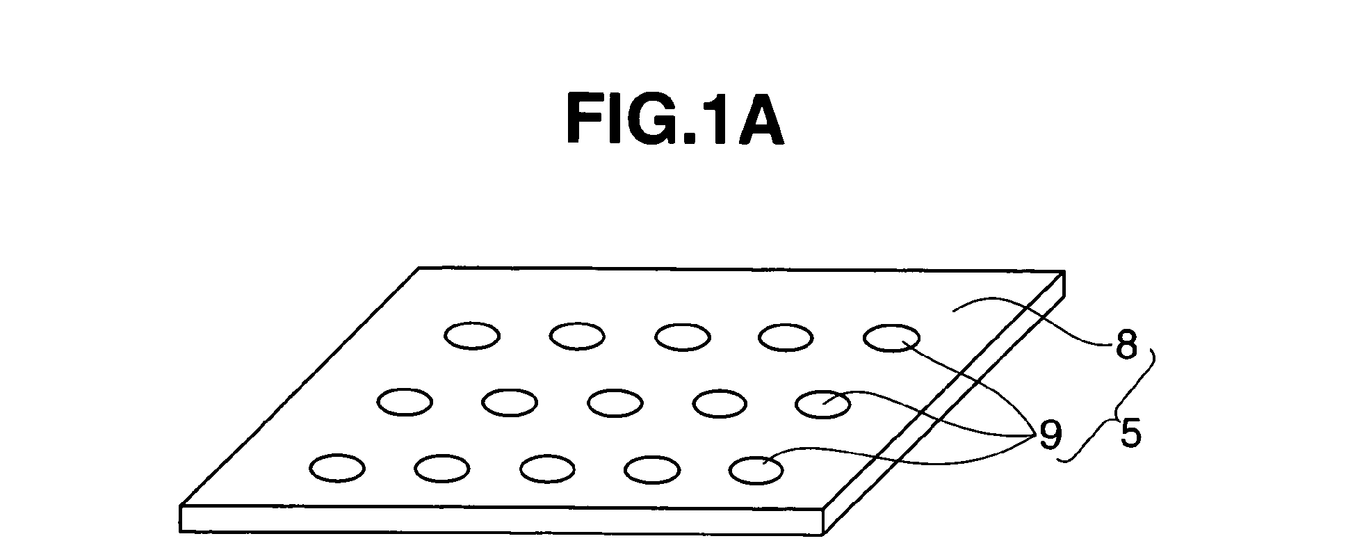
- FIG. 1A is a perspective view of a device (an insulator supporting means) for inspecting a spark plug insulator for bending, according to an embodiment of the invention, before setting the spark plug insulator to the device.
- the spark plug insulator (1) In the device (4) and the method for inspecting a spark plug insulator (1) for bending of the present invention, if the spark plug insulator (1) has a bend as a defect, the spark plug insulator can be pushed out (or slid) by an inspection pin (6). Therefore, it is possible to remarkably facilitate detection of the bending of the spark plug insulator (1) as compared to the conventional visual inspection in which deflection of the spark plug insulator (1) is checked by naked eyes by rotating the spark plug insulator (1). As a result, an accuracy in the bending inspection can be enhanced.
- an insulator supporting means (5) is a holder plate (8) having a holding hole (9), it is possible to realize the insulator supporting means (5) with a simple structure and a reduced cost. Further, even if the spark plug insulators (1) are of different types which are different in size in a longitudinal direction thereof from each other, the spark plug insulators can be inspected using the same device (4) as long as the body (10) and the flange (3) of the spark plug insulators (1) have the same diameters, respectively. Therefore, the device has an increased flexibility.
- the plurality of the spark plug insulators (1) can be simultaneously inspected. As a result, it is possible to remarkably increase an inspection efficiency as compared to the conventional case where the spark plug insulators are inspected one by one.
- the detecting means (7) is an ink pad
- the ink can be adhered to a tip end portion of the spark plug insulator (1) that has a bend as a defect. Therefore, even after removing the inspecting pin (6) from the spark plug insulator, the bent spark plug insulator (1) can be readily detected. As a result, it is possible to enhance the inspection efficiency.
- the bent spark plug insulator (1) can be readily distinguished from the remaining normal spark plug insulators (1) by using the ink pad as the detecting means (7) even after the inspecting pins (6) are removed from the spark plug insulators. Therefore, it is possible to perform simultaneous inspection of the plurality of the spark plug insulators (1) and further enhance the inspection efficiency.
- the detecting means (7) is an electric conduction device that is constituted of the inspection pin (6) having an electric conductivity and a contact portion that has an electric conductivity and is so disposed as to come into contact with the inspection pin (6) when the inspection pin (6) is moved to penetrate the through hole (2)
- the sliding movement of the spark plug insulator (1) can be detected when the inspection pin (6) is prevented from penetrating the through hole and coming into contact with the contact portion and fails to establish an electric conduction therebetween.
- the detecting means (7) is configured to check the sliding movement of the spark plug insulator (1) by visual observation, it is unnecessary to use a special device serving as the inspecting means, and therefore, the inspection can be performed with a reduced cost.
- the detecting means (7) is an optical sensor
- the sliding movement of the spark plug insulator (1) can be detected on the basis of change in quantity of light received by the optical sensor. As a result, it is possible to automatically and readily perform the inspection of the spark plug insulator and thereby enhance the inspection efficiency.
- the spark plug insulator (1) in the method for manufacturing a spark plug insulator (1) according to the present invention, in the step of producing the spark plug insulator (1), it is possible to readily detect bending of the spark plug insulator (1) and thereby surely determine presence or absence of bending in the spark plug insulator (1). Accordingly, in the step of producing the spark plug insulator (1), the spark plug insulator (1) can be produced while certainly excluding a defective one.
- the present invention can be widely applied to general inspections of a spark plug insulator constituting a spark plug that is used for ignition in an internal combustion engine.
- the present invention can suitably provide a device for inspecting a spark plug insulator for bending and a method for inspecting the spark plug insulator for bending, in which it is required to perform the inspection with a high inspection efficiency and a high inspection accuracy, and a method for manufacturing the spark plug insulator which includes the step of inspection for bending as described above.
- Device 4 for inspecting spark plug insulator 1 includes insulator supporting means 5, inspection pin 6 and detecting means 7.
- spark plug insulator (1) includes cylindrical body 10 having radially enlarged flange 3 formed at an axially intermediate portion of body 10. Through hole 2 is formed in body 10 along an axial direction of body 10, into which a center electrode and a terminal electrode are inserted. Spark plug insulator 1 is not limited to specific ones with respect to size, shape, material and number as long as through hole 2 is formed in body 10 along the axial direction of body 10 as described above.
- Insulator supporting means (5) is not limited to specific ones with respect to size, shape, material and number as long as insulator supporting means 5 supports spark plug insulator 1 so as to be slidable in an axial direction of spark plug insulator 1.
- Insulator supporting means 5 may be configured into holder plate 8 having holding hole 9 in which spark plug insulator 1 is supported by engagement between a peripheral edge of holding hole 9 and flange 3. In this case, by setting holder plate 8 substantially horizontally, spark plug insulator 1 can be inserted into holding hole 9 from above until flange 3 is engaged with the peripheral edge of holding hole 9 to thereby support spark plug insulator 1.
- inspection pin (6) is not limited to a specific one with respect to size, shape, material and number as long as inspection pin 6 is inserted into through hole 2 of spark plug insulator 1 that is supported by insulator supporting means 5.
- a plurality of inspection pins 6 can be arranged in a row or multiple rows. As a diameter of inspection pin 6 becomes closer to a diameter of through hole 2, inspection pin 6 can more sensitively interfere with a bend of through hole 2 upon insertion thereof. Therefore, the inspection accuracy can be enhanced by increasing the diameter of inspection pin 6.
- detecting means (7) is not limited to a specific one with respect to the detection method as long as detecting means (7) detects a sliding movement of spark plug insulator 1 when spark plug insulator 1 is caused to slide in the axial direction thereof by inspection pin 6 that is prevented from completely penetrating through hole 2 of spark plug insulator 1 owing to bending of spark plug insulator 1 which exceeds a predetermined tolerance.
- detecting means 7 can be an ink pad that is impregnated with an ink and brought into contact with a tip end of spark plug insulator 1 when slid.
- detecting means 7 can be an electric conduction device which is constituted of inspection pin 6 having an electric conductivity, and a contact portion that has an electric conductivity and is configured to come into contact with inspection pin 6 when inspection pin 6 penetrates through hole 2.
- detecting means 7 can be configured to check the slide movement of spark plug insulator 1 by visual observation.
- detecting means 7 can be a photoelectric sensor that is constructed to detect the sliding movement of spark plug insulator 1 on the basis of change in quantity of light received by a light-receptor element of the photoelectric sensor which is caused when spark plug insulator 1 intercepts or reflects the light during the sliding movement.
- Spark plug insulator 1 that is used as an object to be inspected in the embodiment is a spark plug insulator after baking but before glazing.
- spark plug insulator 1 as an object to be inspected in the embodiment includes cylindrical body 10 having a radially enlarged flange 3 that is formed at an axially intermediate portion of body 10. Spark plug insulator 1 further includes through hole 2 formed in body 10 along an axial direction of body 10 for insertion of a center electrode and a terminal electrode thereinto. Specifically, in FIG. 1B , FIG. 1C and FIG. 2 , spark plug insulator 1 has a base portion on a lower side of flange 3 which has a cylindrical straight barrel shape, and a tip end portion on an upper side of flange 3 which has a tapered shape gradually reduced in diameter toward a tip end thereof.
- Through hole 2 is a stepped hole having an inner diameter on a side of the tip end portion of spark plug insulator 1 which is smaller than an inner diameter on a side of the base portion of spark plug insulator 1.
- the inner diameter of through hole 2 on the side of the base portion is about 3 to 5 mm
- the inner diameter of through hole 2 on the side of the tip end portion is about 1 to 3 mm.
- Device 4 for inspecting spark plug insulator 1 for bending includes insulator supporting member (insulator supporting means) 5 that supports spark plug insulator 1, inspection pin 6 that is to be inserted into through hole 2 of spark plug insulator 1, and detecting member (detecting means) 7 that detects a sliding movement of spark plug insulator 1.
- insulator supporting member 5 is constituted of holder plate 8 substantially horizontally disposed and a plurality of holding holes 9 formed in holder plate 8.
- Each of holding holes 9 has a diameter that is smaller than an outer diameter of flange of spark plug insulator 1 and larger than an outer diameter of body 10 on the base portion of spark plug insulator 1.
- Inspection pin 6 straightly linearly extends and has a stepped shape having a tapered tip end portion similar to an inner circumferential surface of through hole 2.
- Inspection pin 6 has a large diameter portion having an outer diameter smaller by about 1% to 3% than the inner diameter of through hole 2 on the side of the base portion of spark plug insulator 1.
- Inspection pin 6 also has a small diameter portion having an outer diameter smaller by about 1% to 3% than the inner diameter of through hole 2 on the side of the tip end portion of spark plug insulator 1.
- a plurality of inspection pins 6 are arranged in a row and inserted into through hole 2 from a lower side of spark plug insulators 1 vertically supported by insulator supporting member 5.
- Detecting member 7 is disposed in a position where the tip end of spark plug insulator 1 is brought into contact with detecting member 7 when spark plug insulator 1 is caused to upwardly slide in the axial direction thereof by inspection pin 6 that is prevented from completely penetrating through hole 2 owing to bending of spark plug insulator 1 which exceeds a predetermined tolerance.
- detecting member 7 is an ink pad impregnated with an ink.
- spark plug insulators 1 are inserted into holding holes 9 of insulator supporting member 5 as shown in FIG. 1A and supported by insulator supporting member 5 as shown in FIG. 1B .
- Detecting member 7 is placed above spark plug insulators 1 at a suitable distance therefrom.
- inspection pins 6 are upwardly moved from a lower side of insulator supporting member 5 and inserted into through holes 2 of spark plug insulators 1.
- inspection pin 6 can be moved to penetrate through hole 2 and project beyond the tip end portion of spark plug insulator 1 so that spark plug insulator 1 is free from the sliding movement relative to insulator supporting member 5 as shown on the left side of FIG. 2 .
- inspection pin 6 can interfere with a bend of through hole 2' which is located in the axial direction of spark plug insulator 1', and can upwardly push spark plug insulator 1' and cause the slide movement of spark plug insulator 1' relative to insulator supporting member 5 as shown on the right side of FIG. 2 .
- the tip end of spark plug insulator 1 upwardly pushed is contacted with detecting member 7 to thereby cause adhesion of the ink to the tip end of spark plug insulator 1.
- spark plug insulator 1 suffering from the bending is then rejected and removed.
- spark plug insulator 1 with bending can be readily distinguished from multiple normal spark plug insulators 1 even after removing inspection pins 6 therefrom. This results in enhancing the inspection efficiency. Further, since a plurality of inspection pins 6 are arranged in a row, a plurality of spark plug insulators 1 can be inspected at the same time. As a result, it is possible to enhance the inspection efficiency and increase the productivity.
- respective spark plug insulators 1 are supported at flanges 3 by merely the engagement with the peripheral edges of holding holes 9 of insulator supporting member 5. With this arrangement, respective spark plug insulators 1 can be readily upwardly slid relative to insulator supporting member 5. Accordingly, when inspection pin 6 is inserted into through hole 2 from the lower side of spark plug insulator 1 with the bending, inspection pin 6 can be prevented from being bent along through hole 2. Therefore, it is possible to suppress deterioration in inspection accuracy.
- the present invention is not limited to the embodiment described above. Modifications and variations of the embodiment described above will be made in accordance with an object and application unless departing from the scope of the invention.
- a sensor that detects the sliding movement of spark plug insulator 1 can be used without being limited to the ink pad.
- a non-contact sensor such as an optical sensor, or a contact sensor such as a micro switch can also be used for detecting the sliding movement of spark plug insulator 1. In this case, the sliding movement of spark plug insulator 1 can be automatically detected, and therefore, an operability of the inspecting device can be enhanced.
- detecting member 7 can be an electric conduction device that is constituted of inspection pin 6 having an electric conductivity and a contact portion that has an electric conductivity and is so disposed as to come into contact with a tip end of inspection pin 6 which penetrates through hole 2 and projects beyond the tip end portion of spark plug insulator 1 to thereby establish an electric conduction between inspection pin 6 and the contact portion.
- a terminal as the contact portion is provided at the tip end portion of spark plug insulator 1, and it is determined whether or not inspection pin 6 is contacted with the contact portion.
- the sliding movement of spark plug insulator 1 can be automatically detected, and therefore, an operability of the inspecting device can be enhanced.
- detecting member 7 can be configured to check the sliding movement of spark plug insulator 1 by visual observation. In this case, detecting member 7 can be obtained at a reduced cost.
- spark plug insulators 1 of the above-described embodiment are supported so as to be slidable only in an upward direction, but the sliding movement of spark plug insulators 1 is not limited to the above-described embodiment. Spark plug insulators 1 can be supported so as to be slidable in a downward direction or in a horizontal direction or slidable at a certain angle relative to the horizontal direction. In this case, inspection pins 6 can be inserted into spark plug insulators 1 in the same direction as the direction of the sliding movement of spark plug insulators 1.
- inspection pins 6 are arranged in a row in the above-described embodiment, the arrangement of inspection pins 6 is not limited to the above-described embodiment. For instance, a plurality of inspection pins 6 can be arranged in a plurality of rows, or a single inspection pin 6 can be used.
- spark plug insulators 1 are slidably supported in the above-described embodiment, spark plug insulators 1 can be fixedly supported without being limited to the above-described embodiment. In this case, inspection pins 6 can be slidably supported and inserted into spark plug insulators 1 to thereby detect the sliding movement of inspection pins 6.
- the method for manufacturing spark plug insulator 1 can include the step of inserting spark plug insulator 1 and the step of determining presence or absence of bending in spark plug insulator 1. That is, the step of inserting spark plug insulator 1 and the step of determining presence or absence of bending in spark plug insulator 1 in the above-described embodiment are conducted subsequent to the step of producing spark plug insulator 10 with body 10 and through hole 2 by forming a compact from a raw material powder for the spark plug insulator, such as alumina powder, and baking the compact after forming the compact.
- a raw material powder for the spark plug insulator such as alumina powder
- spark plug insulator 1 In such a method for manufacturing spark plug insulator 1, it is possible to readily detect bending as a defect of spark plug insulator 1 and thereby certainly determine presence or absence of the bending in spark plug insulator 1. Accordingly, in the method for manufacturing spark plug insulator 1, it is possible to manufacture spark plug insulator 1 with certainly rejecting the defective product.
Landscapes
- Engineering & Computer Science (AREA)
- Manufacturing & Machinery (AREA)
- Spark Plugs (AREA)
Abstract

Description
- The present invention relates to a device for inspecting a spark plug insulator for bending which constitutes a spark plug useable for ignition in an internal combustion engine, a method for inspecting a spark plug insulator for bending, and a method for manufacturing the spark plug insulator. More specifically, the present invention relates to a device for inspecting a spark plug insulator for bending and a method for inspecting a spark plug insulator for bending with high inspection efficiency and high inspection accuracy, and a method for manufacturing the spark plug insulator.
- In a spark plug that is used in an internal combustion engine such as an automobile engine, an alumina material sintered body made by sintering an alumina (Al2O3) insulating material is practically used as a spark plug insulator (hereinafter also referred to as simply "insulator") which constitutes the spark plug. The reason for using the alumina material sintered body as the insulator is that alumina is excellent in heat resistance, mechanical properties and dielectric strength. Generally, the insulator is formed into an elongated shape in an axial direction thereof and formed with a through hole that extends in the axial direction of the insulator. The through hole receives a center electrode that is opposed to a ground electrode so as to form a spark discharge gap therebetween, and a terminal electrode for applying high discharge voltage to the center electrode.
- The insulator is produced by baking a compact formed of raw material powder. More specifically explaining a generally known method for manufacturing the insulator, first, raw material powder containing alumina powder as a main component is mixed with an organic bonding agent (i.e., a so-called binder) and water as a solvent. The thus formed admixture is wet-blended to form a slurry. The slurry is dried by a suitable method such as spray drying, and then granulated. Next, the granulated material is formed into a compact having a given shape of the above-described insulator and then baked to thereby produce the insulator. There has been conventionally used the raw material powder containing alumina powder as a main component as described above, and specifically, the raw material powder having an average grain size of 2 µm in view of stabilization of quality of the insulator and cost saving and productivity of the insulator (for instance, see Patent Literature 1).
- The insulator formed by the baking was shrunk by about 20% as compared to that before being baked. In a case where the shrinkage occurs non-uniformly upon the baking, bending (warpage or deflection) occurs in the insulator. The bending of the insulator causes a tip end of the center electrode to be displaced from an axis of the center electrode upon assembling the center electrode to the insulator. If the tip end of the center electrode is displaced from the axis of the center electrode, there may occur ignition failure that in turn causes failure in ignition which tends to be ordinarily generated between the center electrode and the ground electrode. That is, there may occur a so-called transverse flying spark that is generated between the center electrode and a main metallic fitting that is disposed on an outer circumferential periphery of the center electrode. Therefore, the bending of the insulator is one of most considerable defects which lead to deterioration in performance of the spark plug.
- Conventionally, there have been proposed a method for inspecting insulators for bending in which the insulators are subjected to visual inspection as to whether or not any deflection is caused in the insulators while the insulators are rotated one by one about a longitudinal axis thereof.
- However, in the above-described inspection method for the insulator, since the presence of the bending of the insulator is determined by the visual inspection, excessive detection of the bending will be frequently caused to thereby decrease the inspection accuracy.
- Patent Literature 1: Japanese Patent Application First Publication No.
2002-305069 - The present invention has been made in view of the above problem in the conventional art. An object of the present invention is to provide a device for inspecting a spark plug insulator for bending, a method for inspecting a spark plug insulator for bending, in which the inspection can be performed with an enhanced inspection accuracy, and a method for manufacturing the spark plug insulator.
- To solve the above problem in the conventional art, in a first aspect of the present invention, there is provided a device (a first device) for inspecting a spark plug insulator for bending, the spark plug insulator including a cylindrical body having a radially enlarged flange at an axially intermediate portion thereof, and a through hole that is formed in the body along an axial direction of the body, the device comprising:
- an insulator supporting means for supporting the spark plug insulator so as to be slidable in an axial direction of the spark plug insulator;
- a linear inspection pin that is to be inserted into the through hole of the spark plug insulator supported by the insulator supporting means; and
- a detecting means for detecting a sliding movement of the spark plug insulator when the spark plug insulator is caused to slide in the axial direction thereof by the inspection pin that is prevented from completely penetrating the through hole of the spark plug insulator owing to bending of the spark plug insulator which exceeds a predetermined tolerance.
- The first device may be a device (a second device) for inspecting the spark plug insulator for bending, in which the insulator supporting means is a holder plate having a holding hole that is engaged with the flange to thereby support the spark plug insulator.
- The first or second device may be a device (a third device) for inspecting the spark plug insulator for bending, in which the insulator supporting means supports a plurality of the spark plug insulators which are arranged in a row or rows, and a plurality of the inspection pins are correspondingly arranged in a row or rows.
- Any one of the first to third device may be a device (a fourth device) for inspecting the spark plug insulator for bending, in which the detecting means is an ink pad that is impregnated with an ink, and the sliding movement of the spark plug insulator is detected by adhesion of the ink to a tip end of the spark plug insulator.
- Any one of the first to third device may be a device (a fifth device) for inspecting the spark plug insulator for bending, in which the detecting means is an electric conduction device that is constituted of the inspection pin having an electric conductivity and a contact portion that has an electric conductivity and is so disposed as to come into contact with the inspection pin when the inspection pin is moved to penetrate the through hole, wherein the sliding movement of the spark plug insulator is detected when the inspection pin is prevented from coming into contact with the contact portion and fails to establish an electric conduction therebetween.
- Any one of the first to third device may be a device (a sixth device) for inspecting the spark plug insulator for bending, in which the detecting means is configured to check the sliding movement of the spark plug insulator by visual observation.
- Any one of the first to third devices may be a device (a seventh device) for inspecting the spark plug insulator for bending, in which the detecting means is an optical sensor that is constructed to detect the sliding movement of the spark plug insulator on the basis of change in quantity of light received by the optical sensor.
- In a second aspect of the present invention, there is provided a method for inspecting the spark plug insulator for bending by using any one of the first to seventh device according to the present invention, the method comprising the steps of:
- moving at least one of the inspection pin and the insulator supporting means with the spark plug insulator supported thereon, so as to approach to each other and inserting the inspection pin into the through hole of the spark plug insulator; and
- determining presence or absence of bending in the spark plug insulator by detecting the sliding movement of the spark plug insulator using the detecting means.
- In a third aspect of the present invention, there is provided a method for manufacturing a spark plug insulator, the spark plug insulator including a cylindrical body having a radially enlarged flange at an axially intermediate portion thereof, and a through hole formed in the body along an axial direction of the body, the method comprising the steps of:
- producing the spark plug insulator with the body and the through hole by baking a compact formed from a raw material powder;
- inserting a linear inspection pin into the through hole of the spark plug insulator produced in the previous step under a condition that the spark plug insulator is slidably supported in an axial direction thereof; and
- determining presence or absence of bending in the spark plug insulator by detecting occurrence or non-occurrence of an axial sliding movement of the spark plug insulator by insertion of the inspection pin.
-
FIG. 1A is a perspective view of a device (an insulator supporting means) for inspecting a spark plug insulator for bending, according to an embodiment of the invention, before setting the spark plug insulator to the device. -
FIG. 1B is a perspective view of the device for inspecting a spark plug insulator for bending, according to the embodiment of the invention, after setting the spark plug insulator to the device. -
FIG. 1C is a perspective view of the device for inspecting a spark plug insulator for bending, according to the embodiment of the invention, showing the spark plug insulator undergoing the inspection. -
FIG. 2 is a vertical sectional view of the spark plug insulator with an inspection pin inserted into the spark plug insulator. - In the device (4) and the method for inspecting a spark plug insulator (1) for bending of the present invention, if the spark plug insulator (1) has a bend as a defect, the spark plug insulator can be pushed out (or slid) by an inspection pin (6). Therefore, it is possible to remarkably facilitate detection of the bending of the spark plug insulator (1) as compared to the conventional visual inspection in which deflection of the spark plug insulator (1) is checked by naked eyes by rotating the spark plug insulator (1). As a result, an accuracy in the bending inspection can be enhanced.
- Further, in a case where an insulator supporting means (5) is a holder plate (8) having a holding hole (9), it is possible to realize the insulator supporting means (5) with a simple structure and a reduced cost. Further, even if the spark plug insulators (1) are of different types which are different in size in a longitudinal direction thereof from each other, the spark plug insulators can be inspected using the same device (4) as long as the body (10) and the flange (3) of the spark plug insulators (1) have the same diameters, respectively. Therefore, the device has an increased flexibility.
- Further, in a case where a plurality of the spark plug insulators (1) are supported in a row or rows by the insulator supporting means (5) and a plurality of the inspection pins (6) are correspondingly arranged in a row or rows, the plurality of the spark plug insulators (1) can be simultaneously inspected. As a result, it is possible to remarkably increase an inspection efficiency as compared to the conventional case where the spark plug insulators are inspected one by one.
- Further, in a case where the detecting means (7) is an ink pad, the ink can be adhered to a tip end portion of the spark plug insulator (1) that has a bend as a defect. Therefore, even after removing the inspecting pin (6) from the spark plug insulator, the bent spark plug insulator (1) can be readily detected. As a result, it is possible to enhance the inspection efficiency. In particular, in a case where a plurality of the spark plug insulators (1) are simultaneously inspected, the bent spark plug insulator (1) can be readily distinguished from the remaining normal spark plug insulators (1) by using the ink pad as the detecting means (7) even after the inspecting pins (6) are removed from the spark plug insulators. Therefore, it is possible to perform simultaneous inspection of the plurality of the spark plug insulators (1) and further enhance the inspection efficiency.
- Further, in a case where the detecting means (7) is an electric conduction device that is constituted of the inspection pin (6) having an electric conductivity and a contact portion that has an electric conductivity and is so disposed as to come into contact with the inspection pin (6) when the inspection pin (6) is moved to penetrate the through hole (2), the sliding movement of the spark plug insulator (1) can be detected when the inspection pin (6) is prevented from penetrating the through hole and coming into contact with the contact portion and fails to establish an electric conduction therebetween. As a result, it is possible to automatically and readily perform the inspection of the spark plug insulator and thereby enhance the inspection efficiency.
- Further, in a case where the detecting means (7) is configured to check the sliding movement of the spark plug insulator (1) by visual observation, it is unnecessary to use a special device serving as the inspecting means, and therefore, the inspection can be performed with a reduced cost.
- Further, in a case where the detecting means (7) is an optical sensor, the sliding movement of the spark plug insulator (1) can be detected on the basis of change in quantity of light received by the optical sensor. As a result, it is possible to automatically and readily perform the inspection of the spark plug insulator and thereby enhance the inspection efficiency.
- Further, in the method for manufacturing a spark plug insulator (1) according to the present invention, in the step of producing the spark plug insulator (1), it is possible to readily detect bending of the spark plug insulator (1) and thereby surely determine presence or absence of bending in the spark plug insulator (1). Accordingly, in the step of producing the spark plug insulator (1), the spark plug insulator (1) can be produced while certainly excluding a defective one.
- As explained above, the present invention can be widely applied to general inspections of a spark plug insulator constituting a spark plug that is used for ignition in an internal combustion engine. In particular, the present invention can suitably provide a device for inspecting a spark plug insulator for bending and a method for inspecting the spark plug insulator for bending, in which it is required to perform the inspection with a high inspection efficiency and a high inspection accuracy, and a method for manufacturing the spark plug insulator which includes the step of inspection for bending as described above.
- The present invention is explained hereinafter with reference to the accompanying drawings.
-
Device 4 for inspectingspark plug insulator 1, according to an embodiment, includesinsulator supporting means 5,inspection pin 6 and detectingmeans 7. - The above-described "spark plug insulator (1)" includes
cylindrical body 10 having radially enlargedflange 3 formed at an axially intermediate portion ofbody 10. Throughhole 2 is formed inbody 10 along an axial direction ofbody 10, into which a center electrode and a terminal electrode are inserted.Spark plug insulator 1 is not limited to specific ones with respect to size, shape, material and number as long as throughhole 2 is formed inbody 10 along the axial direction ofbody 10 as described above. - The above-described "insulator supporting means (5)" is not limited to specific ones with respect to size, shape, material and number as long as
insulator supporting means 5 supports sparkplug insulator 1 so as to be slidable in an axial direction ofspark plug insulator 1.Insulator supporting means 5 may be configured intoholder plate 8 having holdinghole 9 in whichspark plug insulator 1 is supported by engagement between a peripheral edge of holdinghole 9 andflange 3. In this case, by settingholder plate 8 substantially horizontally,spark plug insulator 1 can be inserted into holdinghole 9 from above untilflange 3 is engaged with the peripheral edge of holdinghole 9 to thereby supportspark plug insulator 1. - The above-described "inspection pin (6)" is not limited to a specific one with respect to size, shape, material and number as long as
inspection pin 6 is inserted into throughhole 2 ofspark plug insulator 1 that is supported byinsulator supporting means 5. A plurality of inspection pins 6 can be arranged in a row or multiple rows. As a diameter ofinspection pin 6 becomes closer to a diameter of throughhole 2,inspection pin 6 can more sensitively interfere with a bend of throughhole 2 upon insertion thereof. Therefore, the inspection accuracy can be enhanced by increasing the diameter ofinspection pin 6. - The above-described "detecting means (7)" is not limited to a specific one with respect to the detection method as long as detecting means (7) detects a sliding movement of
spark plug insulator 1 whenspark plug insulator 1 is caused to slide in the axial direction thereof byinspection pin 6 that is prevented from completely penetrating throughhole 2 ofspark plug insulator 1 owing to bending ofspark plug insulator 1 which exceeds a predetermined tolerance. For instance, detectingmeans 7 can be an ink pad that is impregnated with an ink and brought into contact with a tip end ofspark plug insulator 1 when slid. Specifically, whenspark plug insulator 1 is caused to slide byinspection pin 6 such that the tip end thereof comes into contact with the ink pad, the ink in the ink pad is adhered to the tip end ofspark plug insulator 1. Thus, the sliding movement ofspark plug insulator 1 can be detected by the adhesion of the ink. Further, detectingmeans 7 can be an electric conduction device which is constituted ofinspection pin 6 having an electric conductivity, and a contact portion that has an electric conductivity and is configured to come into contact withinspection pin 6 wheninspection pin 6 penetrates throughhole 2. That is, the sliding movement ofspark plug insulator 1 can be detected whenspark plug insulator 1 is slid byinspection pin 6 that is prevented from penetrating throughhole 2 and coming into contact with the contact portion and thereby fails to establish an electric conduction betweeninspection pin 6 and the contact portion. Further, detectingmeans 7 can be configured to check the slide movement ofspark plug insulator 1 by visual observation. Further, detectingmeans 7 can be a photoelectric sensor that is constructed to detect the sliding movement ofspark plug insulator 1 on the basis of change in quantity of light received by a light-receptor element of the photoelectric sensor which is caused whenspark plug insulator 1 intercepts or reflects the light during the sliding movement. - An embodiment of the present invention is explained in more detail hereinafter with reference to the accompanying drawings.
Spark plug insulator 1 that is used as an object to be inspected in the embodiment is a spark plug insulator after baking but before glazing. - As shown in
FIG. 1B ,FIG. 1C andFIG. 2 ,spark plug insulator 1 as an object to be inspected in the embodiment includescylindrical body 10 having a radiallyenlarged flange 3 that is formed at an axially intermediate portion ofbody 10.Spark plug insulator 1 further includes throughhole 2 formed inbody 10 along an axial direction ofbody 10 for insertion of a center electrode and a terminal electrode thereinto. Specifically, inFIG. 1B ,FIG. 1C andFIG. 2 ,spark plug insulator 1 has a base portion on a lower side offlange 3 which has a cylindrical straight barrel shape, and a tip end portion on an upper side offlange 3 which has a tapered shape gradually reduced in diameter toward a tip end thereof. Throughhole 2 is a stepped hole having an inner diameter on a side of the tip end portion ofspark plug insulator 1 which is smaller than an inner diameter on a side of the base portion ofspark plug insulator 1. In general, the inner diameter of throughhole 2 on the side of the base portion is about 3 to 5 mm, and the inner diameter of throughhole 2 on the side of the tip end portion is about 1 to 3 mm. -
Device 4 for inspectingspark plug insulator 1 for bending, according to the embodiment, includes insulator supporting member (insulator supporting means) 5 that supportsspark plug insulator 1,inspection pin 6 that is to be inserted into throughhole 2 ofspark plug insulator 1, and detecting member (detecting means) 7 that detects a sliding movement ofspark plug insulator 1. - As shown in
FIG. 1A ,insulator supporting member 5 is constituted ofholder plate 8 substantially horizontally disposed and a plurality of holdingholes 9 formed inholder plate 8. Each of holdingholes 9 has a diameter that is smaller than an outer diameter of flange ofspark plug insulator 1 and larger than an outer diameter ofbody 10 on the base portion ofspark plug insulator 1. With this configuration of holdinghole 9, whenbody 10 ofspark plug insulator 1 is inserted into holdinghole 9,flange 3 is engaged with the peripheral edge of holdinghole 9 as shown inFIG. 1B , so thatspark plug insulator 1 is vertically supported and upwardly slidable in the axial direction thereof. Holdingholes 9 are arranged in multiple rows at a predetermined interval between adjacent holding holes 9. -
Inspection pin 6 straightly linearly extends and has a stepped shape having a tapered tip end portion similar to an inner circumferential surface of throughhole 2.Inspection pin 6 has a large diameter portion having an outer diameter smaller by about 1% to 3% than the inner diameter of throughhole 2 on the side of the base portion ofspark plug insulator 1.Inspection pin 6 also has a small diameter portion having an outer diameter smaller by about 1% to 3% than the inner diameter of throughhole 2 on the side of the tip end portion ofspark plug insulator 1.
In this embodiment, a plurality of inspection pins 6 are arranged in a row and inserted into throughhole 2 from a lower side ofspark plug insulators 1 vertically supported byinsulator supporting member 5. - Detecting
member 7 is disposed in a position where the tip end ofspark plug insulator 1 is brought into contact with detectingmember 7 whenspark plug insulator 1 is caused to upwardly slide in the axial direction thereof byinspection pin 6 that is prevented from completely penetrating throughhole 2 owing to bending ofspark plug insulator 1 which exceeds a predetermined tolerance. In this embodiment, detectingmember 7 is an ink pad impregnated with an ink. - An operation of inspecting
spark plug insulator 1 according to the above-described embodiment will be explained. - First,
spark plug insulators 1 are inserted into holdingholes 9 ofinsulator supporting member 5 as shown inFIG. 1A and supported byinsulator supporting member 5 as shown inFIG. 1B . Detectingmember 7 is placed abovespark plug insulators 1 at a suitable distance therefrom. After that, as shown inFIG. 1C , inspection pins 6 are upwardly moved from a lower side ofinsulator supporting member 5 and inserted into throughholes 2 ofspark plug insulators 1. - As shown in
FIG. 1C andFIG. 2 , in a case where bending ofspark plug insulator 1 is within the predetermined tolerance,inspection pin 6 can be moved to penetrate throughhole 2 and project beyond the tip end portion ofspark plug insulator 1 so thatspark plug insulator 1 is free from the sliding movement relative to insulator supportingmember 5 as shown on the left side ofFIG. 2 . In contrast, in a case where bending of spark plug insulator 1' exceeds the predetermined tolerance,inspection pin 6 can interfere with a bend of through hole 2' which is located in the axial direction of spark plug insulator 1', and can upwardly push spark plug insulator 1' and cause the slide movement of spark plug insulator 1' relative to insulator supportingmember 5 as shown on the right side ofFIG. 2 . The tip end ofspark plug insulator 1 upwardly pushed is contacted with detectingmember 7 to thereby cause adhesion of the ink to the tip end ofspark plug insulator 1. - Subsequently, inspection pins 6 are downwardly pulled and removed from
spark plug insulator 1, and then detectingmember 7 is moved apart fromspark plug insulators 1. At this time, all ofspark plug insulators 1 are supported byinsulator supporting member 5 again, and it is determined thatspark plug insulator 1 with the ink adhered to the tip end thereof suffers from the bending as a defect.Spark plug insulator 1 suffering from the bending is then rejected and removed. - According to the embodiment, since an ink pad is used as detecting
member 7,spark plug insulator 1 with bending can be readily distinguished from multiple normalspark plug insulators 1 even after removinginspection pins 6 therefrom. This results in enhancing the inspection efficiency.
Further, since a plurality of inspection pins 6 are arranged in a row, a plurality ofspark plug insulators 1 can be inspected at the same time. As a result, it is possible to enhance the inspection efficiency and increase the productivity. - Further, respective
spark plug insulators 1 are supported atflanges 3 by merely the engagement with the peripheral edges of holdingholes 9 ofinsulator supporting member 5. With this arrangement, respectivespark plug insulators 1 can be readily upwardly slid relative toinsulator supporting member 5. Accordingly, wheninspection pin 6 is inserted into throughhole 2 from the lower side ofspark plug insulator 1 with the bending,inspection pin 6 can be prevented from being bent along throughhole 2. Therefore, it is possible to suppress deterioration in inspection accuracy. - The present invention is not limited to the embodiment described above. Modifications and variations of the embodiment described above will be made in accordance with an object and application unless departing from the scope of the invention. Specifically, although the ink pad is used as detecting
member 7 in the embodiment described above, a sensor that detects the sliding movement ofspark plug insulator 1 can be used without being limited to the ink pad. A non-contact sensor such as an optical sensor, or a contact sensor such as a micro switch can also be used for detecting the sliding movement ofspark plug insulator 1.
In this case, the sliding movement ofspark plug insulator 1 can be automatically detected, and therefore, an operability of the inspecting device can be enhanced. - Further, detecting
member 7 can be an electric conduction device that is constituted ofinspection pin 6 having an electric conductivity and a contact portion that has an electric conductivity and is so disposed as to come into contact with a tip end ofinspection pin 6 which penetrates throughhole 2 and projects beyond the tip end portion ofspark plug insulator 1 to thereby establish an electric conduction betweeninspection pin 6 and the contact portion. In this case, for instance, a terminal as the contact portion is provided at the tip end portion ofspark plug insulator 1, and it is determined whether or notinspection pin 6 is contacted with the contact portion. The sliding movement ofspark plug insulator 1 can be automatically detected, and therefore, an operability of the inspecting device can be enhanced. - Further, detecting
member 7 can be configured to check the sliding movement ofspark plug insulator 1 by visual observation. In this case, detectingmember 7 can be obtained at a reduced cost. - Further, although
horizontal holder plate 8 with holdingholes 9 which serves asinsulator supporting member 5 is used in the above-described embodiment, a horizontal grid with multiple holding holes can be used without being limited toholder plate 8. Further,spark plug insulators 1 of the above-described embodiment are supported so as to be slidable only in an upward direction, but the sliding movement ofspark plug insulators 1 is not limited to the above-described embodiment.Spark plug insulators 1 can be supported so as to be slidable in a downward direction or in a horizontal direction or slidable at a certain angle relative to the horizontal direction. In this case, inspection pins 6 can be inserted intospark plug insulators 1 in the same direction as the direction of the sliding movement ofspark plug insulators 1. - Further, although a plurality of inspection pins 6 are arranged in a row in the above-described embodiment, the arrangement of inspection pins 6 is not limited to the above-described embodiment. For instance, a plurality of inspection pins 6 can be arranged in a plurality of rows, or a
single inspection pin 6 can be used. - Further, although
spark plug insulators 1 are slidably supported in the above-described embodiment,spark plug insulators 1 can be fixedly supported without being limited to the above-described embodiment. In this case, inspection pins 6 can be slidably supported and inserted intospark plug insulators 1 to thereby detect the sliding movement of inspection pins 6. - Further, the method for manufacturing
spark plug insulator 1 can include the step of insertingspark plug insulator 1 and the step of determining presence or absence of bending inspark plug insulator 1. That is, the step of insertingspark plug insulator 1 and the step of determining presence or absence of bending inspark plug insulator 1 in the above-described embodiment are conducted subsequent to the step of producingspark plug insulator 10 withbody 10 and throughhole 2 by forming a compact from a raw material powder for the spark plug insulator, such as alumina powder, and baking the compact after forming the compact. In such a method for manufacturingspark plug insulator 1, it is possible to readily detect bending as a defect ofspark plug insulator 1 and thereby certainly determine presence or absence of the bending inspark plug insulator 1. Accordingly, in the method for manufacturingspark plug insulator 1, it is possible to manufacturespark plug insulator 1 with certainly rejecting the defective product.
Claims (9)
- A device for inspecting a spark plug insulator for bending, the spark plug insulator including a cylindrical body having a radially enlarged flange at an axially intermediate portion thereof, and a through hole that is formed in the body along an axial direction of the body, the device comprising:an insulator supporting means for supporting the spark plug insulator so as to be slidable in an axial direction of the spark plug insulator;a linear inspection pin that is to be inserted into the through hole of the spark plug insulator supported by the insulator supporting means; anda detecting means for detecting a sliding movement of the spark plug insulator when the spark plug insulator is caused to slide in the axial direction thereof by the inspection pin that is prevented from completely penetrating the through hole of the spark plug insulator owing to bending of the spark plug insulator which exceeds a predetermined tolerance.
- The device for inspecting a spark plug insulator for bending as claimed in claim 1, wherein the insulator supporting means is a holder plate having a holding hole that is engaged with the flange to thereby support the spark plug insulator.
- The device for inspecting a spark plug insulator for bending as claimed in claim 1 or 2, wherein the insulator supporting means supports a plurality of the spark plug insulators which are arranged in a row or rows, and a plurality of the inspection pins are correspondingly arranged in a row or rows.
- The device for inspecting a spark plug insulator for bending as claimed in any one of claims 1 to 3, wherein the detecting means is an ink pad that is impregnated with an ink, and the sliding movement of the spark plug insulator is detected by adhesion of the ink to a tip end of the spark plug insulator.
- The device for inspecting a spark plug insulator for bending as claimed in any one of claims 1 to 3, wherein the detecting means is an electric conduction device that is constituted of the inspection pin having an electric conductivity and a contact portion that has an electric conductivity and is so disposed as to come into contact with the inspection pin when the inspection pin is moved to penetrate the through hole, wherein the sliding movement of the spark plug insulator is detected when the inspection pin is prevented from coming into contact with the contact portion and fails to establish an electric conduction therebetween.
- The device for inspecting a spark plug insulator for bending as claimed in any one of claims 1 to 3, wherein the detecting means is configured to check the sliding movement of the spark plug insulator by visual observation.
- The device for inspecting a spark plug insulator for bending as claimed in any one of claims 1 to 3, wherein the detecting means is an optical sensor that is constructed to detect the sliding movement of the spark plug insulator on the basis of change in quantity of light received by the optical sensor.
- A method for inspecting a spark plug insulator for bending by using the device for inspecting a spark plug insulator for bending as claimed in any one of claims 1 to 7, the method comprising the steps of:moving at least one of the inspection pin and the insulator supporting means with the spark plug insulator supported thereon, so as to approach to each other and inserting the inspection pin into the through hole of the spark plug insulator; anddetermining presence or absence of bending in the spark plug insulator by detecting the sliding movement of the spark plug insulator using the detecting means.
- A method for manufacturing a spark plug insulator, the spark plug insulator including a cylindrical body having a radially enlarged flange at an axially intermediate portion thereof, and a through hole formed in the body along an axial direction of the body, the method comprising the steps of:producing the spark plug insulator with the body and the through hole by baking a compact formed from a raw material powder;inserting a linear inspection pin into the through hole of the spark plug insulator produced in the previous step under a condition that the spark plug insulator is slidably supported in an axial direction thereof; anddetermining presence or absence of bending in the spark plug insulator by detecting occurrence or non-occurrence of an axial sliding movement of the spark plug insulator by insertion of the inspection pin.
Applications Claiming Priority (2)
| Application Number | Priority Date | Filing Date | Title |
|---|---|---|---|
| JP2007299715A JP4310360B2 (en) | 2007-11-19 | 2007-11-19 | Bending inspection device and inspection method for insulator for spark plug |
| PCT/JP2008/070956 WO2009066669A1 (en) | 2007-11-19 | 2008-11-18 | Deflection inspecting device for spark plug insulator, deflection inspecting method for spark plug insulator, and manufacturing method for spark plug insulator |
Publications (3)
| Publication Number | Publication Date |
|---|---|
| EP2214277A1 true EP2214277A1 (en) | 2010-08-04 |
| EP2214277A4 EP2214277A4 (en) | 2014-11-19 |
| EP2214277B1 EP2214277B1 (en) | 2016-02-10 |
Family
ID=40667491
Family Applications (1)
| Application Number | Title | Priority Date | Filing Date |
|---|---|---|---|
| EP08853039.9A Active EP2214277B1 (en) | 2007-11-19 | 2008-11-18 | Deflection inspecting device for spark plug insulator, deflection inspecting method for spark plug insulator, and manufacturing method for spark plug insulator |
Country Status (7)
| Country | Link |
|---|---|
| US (1) | US7938706B2 (en) |
| EP (1) | EP2214277B1 (en) |
| JP (1) | JP4310360B2 (en) |
| KR (1) | KR101467597B1 (en) |
| CN (1) | CN101647163B (en) |
| BR (1) | BRPI0808041B1 (en) |
| WO (1) | WO2009066669A1 (en) |
Families Citing this family (9)
| Publication number | Priority date | Publication date | Assignee | Title |
|---|---|---|---|---|
| US8079154B1 (en) * | 2007-03-26 | 2011-12-20 | The United States Of America As Represented By The Secretary Of The Navy | Apparatus and method for measuring curvature of tubes |
| CN102042796B (en) * | 2009-10-22 | 2014-04-23 | 鸿富锦精密工业(深圳)有限公司 | Verticality detection device |
| CN104567605B (en) * | 2013-10-21 | 2017-06-06 | 珠海格力电器股份有限公司 | Aperture inspection frock |
| CN103747414B (en) * | 2013-12-30 | 2018-07-03 | 华为技术有限公司 | The method and mobile terminal of more new state information |
| US10120015B2 (en) * | 2015-01-30 | 2018-11-06 | Ngk Spark Plug Co., Ltd. | Method for inspecting insulator for spark plug |
| GB2551728B (en) * | 2016-06-28 | 2020-11-18 | Jaguar Land Rover Ltd | Method for configuring a machine for production of a thread |
| JP6708706B2 (en) * | 2018-07-23 | 2020-06-10 | 日本特殊陶業株式会社 | Spark plug manufacturing method |
| CN114935317B (en) * | 2022-05-31 | 2024-06-04 | 国网安徽省电力有限公司电力科学研究院 | Method for detecting deflection degree of disc-shaped suspension porcelain insulator |
| EP4439776A4 (en) * | 2022-09-21 | 2025-05-21 | LG Energy Solution, Ltd. | Apparatus for inspecting the deformation of pouch cells and method for deformation inspection therewith |
Family Cites Families (10)
| Publication number | Priority date | Publication date | Assignee | Title |
|---|---|---|---|---|
| US4982489A (en) * | 1989-10-23 | 1991-01-08 | Honeywell Inc. | Tool set and method for gauging and restoring concentricity between axial sections of a workpiece bore |
| JPH0665110B2 (en) * | 1990-08-03 | 1994-08-22 | 日本特殊陶業株式会社 | One-shot automatic molding device for spark plug base |
| US5639953A (en) * | 1996-02-26 | 1997-06-17 | Hanson Research Corporation | Alignment verification device for a rotating shaft |
| JP3558651B2 (en) * | 1996-10-17 | 2004-08-25 | 松下電器産業株式会社 | Component storage body and component inspection method and apparatus using the component storage body |
| JP2002305069A (en) | 2001-01-31 | 2002-10-18 | Ngk Spark Plug Co Ltd | Method of manufacturing insulator for spark plug, insulator for spark plug, and spark plug including the same |
| JP4422605B2 (en) * | 2004-12-28 | 2010-02-24 | 日本特殊陶業株式会社 | Spark plug insulating body, spark plug manufacturing method, and spark plug |
| JP4686337B2 (en) * | 2005-11-09 | 2011-05-25 | 日本特殊陶業株式会社 | Inspection method and inspection device for insulator for spark plug |
| US7795791B2 (en) * | 2006-08-03 | 2010-09-14 | Federal-Mogul World Wide, Inc. | One piece shell high thread spark plug |
| JP2009231268A (en) * | 2008-02-27 | 2009-10-08 | Ngk Spark Plug Co Ltd | Manufacturing method of insulator for spark plug and spark plug |
| JP2009259775A (en) * | 2008-03-19 | 2009-11-05 | Ngk Spark Plug Co Ltd | Insulator for spark plug and method of manufacturing spark plug |
-
2007
- 2007-11-19 JP JP2007299715A patent/JP4310360B2/en active Active
-
2008
- 2008-11-18 BR BRPI0808041A patent/BRPI0808041B1/en not_active IP Right Cessation
- 2008-11-18 KR KR1020097020873A patent/KR101467597B1/en not_active Expired - Fee Related
- 2008-11-18 US US12/529,827 patent/US7938706B2/en active Active
- 2008-11-18 EP EP08853039.9A patent/EP2214277B1/en active Active
- 2008-11-18 WO PCT/JP2008/070956 patent/WO2009066669A1/en not_active Ceased
- 2008-11-18 CN CN2008800106121A patent/CN101647163B/en active Active
Also Published As
| Publication number | Publication date |
|---|---|
| EP2214277A4 (en) | 2014-11-19 |
| WO2009066669A1 (en) | 2009-05-28 |
| US20100093246A1 (en) | 2010-04-15 |
| KR101467597B1 (en) | 2014-12-01 |
| CN101647163A (en) | 2010-02-10 |
| KR20100075775A (en) | 2010-07-05 |
| US7938706B2 (en) | 2011-05-10 |
| JP4310360B2 (en) | 2009-08-05 |
| CN101647163B (en) | 2013-06-12 |
| BRPI0808041A2 (en) | 2014-06-17 |
| JP2009129544A (en) | 2009-06-11 |
| BRPI0808041B1 (en) | 2018-09-11 |
| EP2214277B1 (en) | 2016-02-10 |
Similar Documents
| Publication | Publication Date | Title |
|---|---|---|
| US7938706B2 (en) | Deflection inspecting device for spark plug insulator, deflection inspecting method for spark plug insulator, and manufacturing method for spark plug insulator | |
| KR102297838B1 (en) | Method for continuously inspecting electric properties of electronic chip component | |
| US9870865B2 (en) | Multilayer ceramic capacitor including a perovskite compound | |
| WO2013187611A1 (en) | Test probe and machining method thereof | |
| KR20060059786A (en) | A probe card and an inspection method of a semiconductor element using the same and a semiconductor device inspected by the inspection method | |
| EP2733800B1 (en) | Method of manufacturing spark plug | |
| JP2010010306A (en) | Semiconductor wafer measuring apparatus | |
| JP2011226859A (en) | Particulate material detection device | |
| KR102208381B1 (en) | Test probe and method manufacturing for the same, and test socket supporting the same | |
| US8593167B2 (en) | Semiconductor device test method and apparatus, and semiconductor device | |
| US8885323B2 (en) | Multilayered ceramic electronic component and fabricating method thereof | |
| EP2913666B1 (en) | Method for inspecting honeycomb structure | |
| CN105352464A (en) | Detection device of specification of wire plug | |
| JP5480075B2 (en) | Inspection jig and contact | |
| JP4779976B2 (en) | Manufacturing method of electronic parts | |
| CN220019336U (en) | Test fixture convenient to test MLCC end electrode adhesive force | |
| JP2014020933A (en) | Partial discharge test apparatus and partial discharge test method | |
| JP2012057995A5 (en) | ||
| EP2869413A1 (en) | Method of manufacturing spark plug | |
| US10644483B2 (en) | Method of inspecting spark plug and method of manufacturing spark plug | |
| CN107218867A (en) | A kind of method of quick detection multi-hole position product | |
| EP4365567A1 (en) | Method for predicting occurrence of electrode crack and delamination | |
| KR20210112071A (en) | Equipment for inspecting characteristics of electric slip ring | |
| CN217425173U (en) | Jig for inspecting appearance of side surface of laminated ceramic capacitor | |
| CN218497112U (en) | High-voltage leakage testing device for ceramic spark plug insulating part |
Legal Events
| Date | Code | Title | Description |
|---|---|---|---|
| PUAI | Public reference made under article 153(3) epc to a published international application that has entered the european phase |
Free format text: ORIGINAL CODE: 0009012 |
|
| 17P | Request for examination filed |
Effective date: 20090824 |
|
| AK | Designated contracting states |
Kind code of ref document: A1 Designated state(s): AT BE BG CH CY CZ DE DK EE ES FI FR GB GR HR HU IE IS IT LI LT LU LV MC MT NL NO PL PT RO SE SI SK TR |
|
| AX | Request for extension of the european patent |
Extension state: AL BA MK RS |
|
| DAX | Request for extension of the european patent (deleted) | ||
| A4 | Supplementary search report drawn up and despatched |
Effective date: 20141016 |
|
| RIC1 | Information provided on ipc code assigned before grant |
Ipc: H01T 13/38 20060101ALN20141010BHEP Ipc: H01T 13/20 20060101ALI20141010BHEP Ipc: H01T 21/02 20060101AFI20141010BHEP Ipc: G01B 5/12 20060101ALI20141010BHEP |
|
| GRAP | Despatch of communication of intention to grant a patent |
Free format text: ORIGINAL CODE: EPIDOSNIGR1 |
|
| RIC1 | Information provided on ipc code assigned before grant |
Ipc: H01T 13/38 20060101ALN20150129BHEP Ipc: G01B 5/12 20060101ALI20150129BHEP Ipc: H01T 13/20 20060101ALI20150129BHEP Ipc: H01T 21/02 20060101AFI20150129BHEP |
|
| GRAJ | Information related to disapproval of communication of intention to grant by the applicant or resumption of examination proceedings by the epo deleted |
Free format text: ORIGINAL CODE: EPIDOSDIGR1 |
|
| INTG | Intention to grant announced |
Effective date: 20150212 |
|
| GRAP | Despatch of communication of intention to grant a patent |
Free format text: ORIGINAL CODE: EPIDOSNIGR1 |
|
| GRAJ | Information related to disapproval of communication of intention to grant by the applicant or resumption of examination proceedings by the epo deleted |
Free format text: ORIGINAL CODE: EPIDOSDIGR1 |
|
| GRAP | Despatch of communication of intention to grant a patent |
Free format text: ORIGINAL CODE: EPIDOSNIGR1 |
|
| INTG | Intention to grant announced |
Effective date: 20150317 |
|
| GRAJ | Information related to disapproval of communication of intention to grant by the applicant or resumption of examination proceedings by the epo deleted |
Free format text: ORIGINAL CODE: EPIDOSDIGR1 |
|
| GRAP | Despatch of communication of intention to grant a patent |
Free format text: ORIGINAL CODE: EPIDOSNIGR1 |
|
| GRAC | Information related to communication of intention to grant a patent modified |
Free format text: ORIGINAL CODE: EPIDOSCIGR1 |
|
| INTG | Intention to grant announced |
Effective date: 20150407 |
|
| INTG | Intention to grant announced |
Effective date: 20150423 |
|
| INTG | Intention to grant announced |
Effective date: 20150504 |
|
| GRAP | Despatch of communication of intention to grant a patent |
Free format text: ORIGINAL CODE: EPIDOSNIGR1 |
|
| RIC1 | Information provided on ipc code assigned before grant |
Ipc: H01T 13/38 20060101ALN20150727BHEP Ipc: H01T 21/02 20060101AFI20150727BHEP Ipc: H01T 13/20 20060101ALI20150727BHEP Ipc: G01B 5/12 20060101ALI20150727BHEP |
|
| INTG | Intention to grant announced |
Effective date: 20150827 |
|
| GRAS | Grant fee paid |
Free format text: ORIGINAL CODE: EPIDOSNIGR3 |
|
| GRAA | (expected) grant |
Free format text: ORIGINAL CODE: 0009210 |
|
| AK | Designated contracting states |
Kind code of ref document: B1 Designated state(s): AT BE BG CH CY CZ DE DK EE ES FI FR GB GR HR HU IE IS IT LI LT LU LV MC MT NL NO PL PT RO SE SI SK TR |
|
| REG | Reference to a national code |
Ref country code: GB Ref legal event code: FG4D |
|
| REG | Reference to a national code |
Ref country code: AT Ref legal event code: REF Ref document number: 775060 Country of ref document: AT Kind code of ref document: T Effective date: 20160215 Ref country code: CH Ref legal event code: EP |
|
| REG | Reference to a national code |
Ref country code: IE Ref legal event code: FG4D |
|
| REG | Reference to a national code |
Ref country code: DE Ref legal event code: R096 Ref document number: 602008042320 Country of ref document: DE |
|
| REG | Reference to a national code |
Ref country code: LT Ref legal event code: MG4D |
|
| REG | Reference to a national code |
Ref country code: NL Ref legal event code: MP Effective date: 20160210 |
|
| REG | Reference to a national code |
Ref country code: AT Ref legal event code: MK05 Ref document number: 775060 Country of ref document: AT Kind code of ref document: T Effective date: 20160210 |
|
| PG25 | Lapsed in a contracting state [announced via postgrant information from national office to epo] |
Ref country code: FI Free format text: LAPSE BECAUSE OF FAILURE TO SUBMIT A TRANSLATION OF THE DESCRIPTION OR TO PAY THE FEE WITHIN THE PRESCRIBED TIME-LIMIT Effective date: 20160210 Ref country code: NO Free format text: LAPSE BECAUSE OF FAILURE TO SUBMIT A TRANSLATION OF THE DESCRIPTION OR TO PAY THE FEE WITHIN THE PRESCRIBED TIME-LIMIT Effective date: 20160510 Ref country code: IT Free format text: LAPSE BECAUSE OF FAILURE TO SUBMIT A TRANSLATION OF THE DESCRIPTION OR TO PAY THE FEE WITHIN THE PRESCRIBED TIME-LIMIT Effective date: 20160210 Ref country code: GR Free format text: LAPSE BECAUSE OF FAILURE TO SUBMIT A TRANSLATION OF THE DESCRIPTION OR TO PAY THE FEE WITHIN THE PRESCRIBED TIME-LIMIT Effective date: 20160511 Ref country code: ES Free format text: LAPSE BECAUSE OF FAILURE TO SUBMIT A TRANSLATION OF THE DESCRIPTION OR TO PAY THE FEE WITHIN THE PRESCRIBED TIME-LIMIT Effective date: 20160210 Ref country code: HR Free format text: LAPSE BECAUSE OF FAILURE TO SUBMIT A TRANSLATION OF THE DESCRIPTION OR TO PAY THE FEE WITHIN THE PRESCRIBED TIME-LIMIT Effective date: 20160210 |
|
| PG25 | Lapsed in a contracting state [announced via postgrant information from national office to epo] |
Ref country code: NL Free format text: LAPSE BECAUSE OF FAILURE TO SUBMIT A TRANSLATION OF THE DESCRIPTION OR TO PAY THE FEE WITHIN THE PRESCRIBED TIME-LIMIT Effective date: 20160210 Ref country code: LV Free format text: LAPSE BECAUSE OF FAILURE TO SUBMIT A TRANSLATION OF THE DESCRIPTION OR TO PAY THE FEE WITHIN THE PRESCRIBED TIME-LIMIT Effective date: 20160210 Ref country code: IS Free format text: LAPSE BECAUSE OF FAILURE TO SUBMIT A TRANSLATION OF THE DESCRIPTION OR TO PAY THE FEE WITHIN THE PRESCRIBED TIME-LIMIT Effective date: 20160610 Ref country code: PT Free format text: LAPSE BECAUSE OF FAILURE TO SUBMIT A TRANSLATION OF THE DESCRIPTION OR TO PAY THE FEE WITHIN THE PRESCRIBED TIME-LIMIT Effective date: 20160613 Ref country code: SE Free format text: LAPSE BECAUSE OF FAILURE TO SUBMIT A TRANSLATION OF THE DESCRIPTION OR TO PAY THE FEE WITHIN THE PRESCRIBED TIME-LIMIT Effective date: 20160210 Ref country code: LT Free format text: LAPSE BECAUSE OF FAILURE TO SUBMIT A TRANSLATION OF THE DESCRIPTION OR TO PAY THE FEE WITHIN THE PRESCRIBED TIME-LIMIT Effective date: 20160210 Ref country code: PL Free format text: LAPSE BECAUSE OF FAILURE TO SUBMIT A TRANSLATION OF THE DESCRIPTION OR TO PAY THE FEE WITHIN THE PRESCRIBED TIME-LIMIT Effective date: 20160210 Ref country code: AT Free format text: LAPSE BECAUSE OF FAILURE TO SUBMIT A TRANSLATION OF THE DESCRIPTION OR TO PAY THE FEE WITHIN THE PRESCRIBED TIME-LIMIT Effective date: 20160210 |
|
| REG | Reference to a national code |
Ref country code: FR Ref legal event code: PLFP Year of fee payment: 9 |
|
| PG25 | Lapsed in a contracting state [announced via postgrant information from national office to epo] |
Ref country code: DK Free format text: LAPSE BECAUSE OF FAILURE TO SUBMIT A TRANSLATION OF THE DESCRIPTION OR TO PAY THE FEE WITHIN THE PRESCRIBED TIME-LIMIT Effective date: 20160210 Ref country code: EE Free format text: LAPSE BECAUSE OF FAILURE TO SUBMIT A TRANSLATION OF THE DESCRIPTION OR TO PAY THE FEE WITHIN THE PRESCRIBED TIME-LIMIT Effective date: 20160210 |
|
| REG | Reference to a national code |
Ref country code: DE Ref legal event code: R097 Ref document number: 602008042320 Country of ref document: DE |
|
| PG25 | Lapsed in a contracting state [announced via postgrant information from national office to epo] |
Ref country code: CZ Free format text: LAPSE BECAUSE OF FAILURE TO SUBMIT A TRANSLATION OF THE DESCRIPTION OR TO PAY THE FEE WITHIN THE PRESCRIBED TIME-LIMIT Effective date: 20160210 Ref country code: RO Free format text: LAPSE BECAUSE OF FAILURE TO SUBMIT A TRANSLATION OF THE DESCRIPTION OR TO PAY THE FEE WITHIN THE PRESCRIBED TIME-LIMIT Effective date: 20160210 Ref country code: SK Free format text: LAPSE BECAUSE OF FAILURE TO SUBMIT A TRANSLATION OF THE DESCRIPTION OR TO PAY THE FEE WITHIN THE PRESCRIBED TIME-LIMIT Effective date: 20160210 |
|
| PLBE | No opposition filed within time limit |
Free format text: ORIGINAL CODE: 0009261 |
|
| STAA | Information on the status of an ep patent application or granted ep patent |
Free format text: STATUS: NO OPPOSITION FILED WITHIN TIME LIMIT |
|
| PG25 | Lapsed in a contracting state [announced via postgrant information from national office to epo] |
Ref country code: BE Free format text: LAPSE BECAUSE OF FAILURE TO SUBMIT A TRANSLATION OF THE DESCRIPTION OR TO PAY THE FEE WITHIN THE PRESCRIBED TIME-LIMIT Effective date: 20160210 |
|
| 26N | No opposition filed |
Effective date: 20161111 |
|
| PG25 | Lapsed in a contracting state [announced via postgrant information from national office to epo] |
Ref country code: BG Free format text: LAPSE BECAUSE OF FAILURE TO SUBMIT A TRANSLATION OF THE DESCRIPTION OR TO PAY THE FEE WITHIN THE PRESCRIBED TIME-LIMIT Effective date: 20160510 Ref country code: SI Free format text: LAPSE BECAUSE OF FAILURE TO SUBMIT A TRANSLATION OF THE DESCRIPTION OR TO PAY THE FEE WITHIN THE PRESCRIBED TIME-LIMIT Effective date: 20160210 |
|
| REG | Reference to a national code |
Ref country code: CH Ref legal event code: PL |
|
| GBPC | Gb: european patent ceased through non-payment of renewal fee |
Effective date: 20161118 |
|
| PG25 | Lapsed in a contracting state [announced via postgrant information from national office to epo] |
Ref country code: CH Free format text: LAPSE BECAUSE OF NON-PAYMENT OF DUE FEES Effective date: 20161130 Ref country code: LI Free format text: LAPSE BECAUSE OF NON-PAYMENT OF DUE FEES Effective date: 20161130 |
|
| REG | Reference to a national code |
Ref country code: IE Ref legal event code: MM4A |
|
| PG25 | Lapsed in a contracting state [announced via postgrant information from national office to epo] |
Ref country code: LU Free format text: LAPSE BECAUSE OF NON-PAYMENT OF DUE FEES Effective date: 20161130 |
|
| REG | Reference to a national code |
Ref country code: FR Ref legal event code: PLFP Year of fee payment: 10 |
|
| PG25 | Lapsed in a contracting state [announced via postgrant information from national office to epo] |
Ref country code: GB Free format text: LAPSE BECAUSE OF NON-PAYMENT OF DUE FEES Effective date: 20161118 Ref country code: IE Free format text: LAPSE BECAUSE OF NON-PAYMENT OF DUE FEES Effective date: 20161118 |
|
| PG25 | Lapsed in a contracting state [announced via postgrant information from national office to epo] |
Ref country code: HU Free format text: LAPSE BECAUSE OF FAILURE TO SUBMIT A TRANSLATION OF THE DESCRIPTION OR TO PAY THE FEE WITHIN THE PRESCRIBED TIME-LIMIT; INVALID AB INITIO Effective date: 20081118 Ref country code: CY Free format text: LAPSE BECAUSE OF FAILURE TO SUBMIT A TRANSLATION OF THE DESCRIPTION OR TO PAY THE FEE WITHIN THE PRESCRIBED TIME-LIMIT Effective date: 20160210 |
|
| PG25 | Lapsed in a contracting state [announced via postgrant information from national office to epo] |
Ref country code: MC Free format text: LAPSE BECAUSE OF FAILURE TO SUBMIT A TRANSLATION OF THE DESCRIPTION OR TO PAY THE FEE WITHIN THE PRESCRIBED TIME-LIMIT Effective date: 20160210 Ref country code: TR Free format text: LAPSE BECAUSE OF FAILURE TO SUBMIT A TRANSLATION OF THE DESCRIPTION OR TO PAY THE FEE WITHIN THE PRESCRIBED TIME-LIMIT Effective date: 20160210 |
|
| PG25 | Lapsed in a contracting state [announced via postgrant information from national office to epo] |
Ref country code: MT Free format text: LAPSE BECAUSE OF NON-PAYMENT OF DUE FEES Effective date: 20161118 |
|
| REG | Reference to a national code |
Ref country code: FR Ref legal event code: PLFP Year of fee payment: 11 |
|
| P01 | Opt-out of the competence of the unified patent court (upc) registered |
Effective date: 20230512 |
|
| REG | Reference to a national code |
Ref country code: DE Ref legal event code: R081 Ref document number: 602008042320 Country of ref document: DE Owner name: NITERRA CO., LTD., NAGOYA-SHI, JP Free format text: FORMER OWNER: NGK SPARK PLUG CO., LTD., NAGOYA-SHI, AICHI, JP |
|
| PGFP | Annual fee paid to national office [announced via postgrant information from national office to epo] |
Ref country code: FR Payment date: 20250930 Year of fee payment: 18 |
|
| PGFP | Annual fee paid to national office [announced via postgrant information from national office to epo] |
Ref country code: DE Payment date: 20250930 Year of fee payment: 18 |