EP2213881A2 - Method of manufacturing impeller, impeller, and compressor having impeller - Google Patents
Method of manufacturing impeller, impeller, and compressor having impeller Download PDFInfo
- Publication number
- EP2213881A2 EP2213881A2 EP10000979A EP10000979A EP2213881A2 EP 2213881 A2 EP2213881 A2 EP 2213881A2 EP 10000979 A EP10000979 A EP 10000979A EP 10000979 A EP10000979 A EP 10000979A EP 2213881 A2 EP2213881 A2 EP 2213881A2
- Authority
- EP
- European Patent Office
- Prior art keywords
- blade
- disk
- impeller
- groove
- cover
- Prior art date
- Legal status (The legal status is an assumption and is not a legal conclusion. Google has not performed a legal analysis and makes no representation as to the accuracy of the status listed.)
- Withdrawn
Links
- 238000004519 manufacturing process Methods 0.000 title claims abstract description 22
- 239000007767 bonding agent Substances 0.000 claims abstract description 16
- 238000000034 method Methods 0.000 claims abstract description 7
- 239000002184 metal Substances 0.000 description 34
- 229910052751 metal Inorganic materials 0.000 description 34
- 239000000945 filler Substances 0.000 description 32
- 230000002093 peripheral effect Effects 0.000 description 24
- 238000005219 brazing Methods 0.000 description 14
- 150000002739 metals Chemical class 0.000 description 9
- 238000003466 welding Methods 0.000 description 8
- 238000010438 heat treatment Methods 0.000 description 7
- 239000007788 liquid Substances 0.000 description 4
- 238000005520 cutting process Methods 0.000 description 3
- 238000009792 diffusion process Methods 0.000 description 3
- 239000007791 liquid phase Substances 0.000 description 3
- 238000003754 machining Methods 0.000 description 3
- 239000000463 material Substances 0.000 description 3
- 230000007547 defect Effects 0.000 description 2
- 238000007747 plating Methods 0.000 description 2
- 239000000843 powder Substances 0.000 description 2
- 229910000975 Carbon steel Inorganic materials 0.000 description 1
- 238000007792 addition Methods 0.000 description 1
- 238000005452 bending Methods 0.000 description 1
- 239000010962 carbon steel Substances 0.000 description 1
- 238000005266 casting Methods 0.000 description 1
- 239000000470 constituent Substances 0.000 description 1
- 238000010892 electric spark Methods 0.000 description 1
- 239000011888 foil Substances 0.000 description 1
- 238000005242 forging Methods 0.000 description 1
- 238000005304 joining Methods 0.000 description 1
- 238000012986 modification Methods 0.000 description 1
- 230000004048 modification Effects 0.000 description 1
- 230000003014 reinforcing effect Effects 0.000 description 1
- 239000012763 reinforcing filler Substances 0.000 description 1
- 239000010935 stainless steel Substances 0.000 description 1
- 229910001220 stainless steel Inorganic materials 0.000 description 1
- 238000006467 substitution reaction Methods 0.000 description 1
- 238000011144 upstream manufacturing Methods 0.000 description 1
Images


Classifications
-
- F—MECHANICAL ENGINEERING; LIGHTING; HEATING; WEAPONS; BLASTING
- F04—POSITIVE - DISPLACEMENT MACHINES FOR LIQUIDS; PUMPS FOR LIQUIDS OR ELASTIC FLUIDS
- F04D—NON-POSITIVE-DISPLACEMENT PUMPS
- F04D29/00—Details, component parts, or accessories
- F04D29/26—Rotors specially for elastic fluids
- F04D29/28—Rotors specially for elastic fluids for centrifugal or helico-centrifugal pumps for radial-flow or helico-centrifugal pumps
- F04D29/284—Rotors specially for elastic fluids for centrifugal or helico-centrifugal pumps for radial-flow or helico-centrifugal pumps for compressors
-
- F—MECHANICAL ENGINEERING; LIGHTING; HEATING; WEAPONS; BLASTING
- F04—POSITIVE - DISPLACEMENT MACHINES FOR LIQUIDS; PUMPS FOR LIQUIDS OR ELASTIC FLUIDS
- F04D—NON-POSITIVE-DISPLACEMENT PUMPS
- F04D29/00—Details, component parts, or accessories
- F04D29/02—Selection of particular materials
- F04D29/023—Selection of particular materials especially adapted for elastic fluid pumps
-
- F—MECHANICAL ENGINEERING; LIGHTING; HEATING; WEAPONS; BLASTING
- F04—POSITIVE - DISPLACEMENT MACHINES FOR LIQUIDS; PUMPS FOR LIQUIDS OR ELASTIC FLUIDS
- F04D—NON-POSITIVE-DISPLACEMENT PUMPS
- F04D29/00—Details, component parts, or accessories
- F04D29/60—Mounting; Assembling; Disassembling
- F04D29/62—Mounting; Assembling; Disassembling of radial or helico-centrifugal pumps
- F04D29/624—Mounting; Assembling; Disassembling of radial or helico-centrifugal pumps especially adapted for elastic fluid pumps
-
- F—MECHANICAL ENGINEERING; LIGHTING; HEATING; WEAPONS; BLASTING
- F05—INDEXING SCHEMES RELATING TO ENGINES OR PUMPS IN VARIOUS SUBCLASSES OF CLASSES F01-F04
- F05D—INDEXING SCHEME FOR ASPECTS RELATING TO NON-POSITIVE-DISPLACEMENT MACHINES OR ENGINES, GAS-TURBINES OR JET-PROPULSION PLANTS
- F05D2230/00—Manufacture
- F05D2230/20—Manufacture essentially without removing material
- F05D2230/23—Manufacture essentially without removing material by permanently joining parts together
-
- Y—GENERAL TAGGING OF NEW TECHNOLOGICAL DEVELOPMENTS; GENERAL TAGGING OF CROSS-SECTIONAL TECHNOLOGIES SPANNING OVER SEVERAL SECTIONS OF THE IPC; TECHNICAL SUBJECTS COVERED BY FORMER USPC CROSS-REFERENCE ART COLLECTIONS [XRACs] AND DIGESTS
- Y10—TECHNICAL SUBJECTS COVERED BY FORMER USPC
- Y10T—TECHNICAL SUBJECTS COVERED BY FORMER US CLASSIFICATION
- Y10T29/00—Metal working
- Y10T29/49—Method of mechanical manufacture
- Y10T29/49316—Impeller making
Definitions
- the present invention relates to a method of manufacturing an impeller used in a centrifugal rotary machine such as a centrifugal compressor, an impeller, and a compressor having the impeller.
- a cover attachment impeller (closed impeller) including a disk attached to a rotary shaft, a cover disposed in the disk while having a gap therebetween, and plural blades connecting the disk and the cover to each other.
- a portion surrounded by a side surface of each blade and stream surfaces of the cover and the disk is formed as a passageway used to compress air.
- the impeller provided in the centrifugal compressor is formed by, for example, integral forming performed by casting, machining, or electric spark machining, or bonding performed by welding, brazing, or liquid phase diffusion bonding after forging and mechanical machining.
- the integral forming is to integrally form the cover, the blade, and the disk by cutting a material.
- the impeller provided in the centrifugal compressor includes a passageway formed in a complex shape in which the passageway is curved in the axial direction (rotary shaft direction) and the radial direction. For this reason, the integral forming is difficult.
- the bonding performed by brazing is known in, for example, JP-A-2003-328989 (hereinafter, Patent Document 1) or JP-A-H07-109997 (hereinafter, Patent Document 2).
- the bonding performed by brazing for example, upon bonding the blade attachment cover to the disk, filler metals such as foils, powders, or wires are disposed in the connection portion, and the cover and the disk are installed and heated in a furnace in a joining state so as to be bonded to each other. Even when the passageway is narrow, the bonding performed by brazing can be easily performed compared with the bonding performed by welding.
- a plating layer is provided both in the combination of a blade and a shroud (cover) and in a hab (disk).
- the hab provided with a groove having an R-part in both sides thereof and the combination is bonded to each other.
- a plating layer is provided both in the combination of the blade and the hab and the shroud.
- the shroud provided with a groove having an R-part in both sides thereof and the combination is bonded to each other.
- the melted filler metal may flow outside during the brazing. That is, in this case, the amount of the filler metal may be not sufficient in a part of the bonding portion, or the filler metal may be lost, which may cause bonding defects. Accordingly, it is not possible to ensure sufficient bonding strength. For this reason, in the bonding performed by brazing, liquid phase diffusion bonding, or the like, there is a demand for a method capable of reliably improving the bonding strength.
- the present invention is contrived in consideration of the above-described problem, and an object of the present invention is to provide a method of manufacturing an impeller capable of improving the bonding strength between a blade and either a disk or a cover, an impeller having a high bonding strength between a blade and either a disk or a cover, and a compressor having an impeller.
- an impeller including a substantially disk-shaped disk, a cover facing the disk, a blade provided between the disk and the cover, the method including: forming a groove in a blade attachment surface of the disk or the cover so as to correspond to the shape of an edge tip of the blade; and bonding an inner surface of the groove to the edge tip of the blade through a bonding agent after inserting the edge tip of the blade into the groove.
- an impeller including: a substantially disk-shaped disk; a cover facing the disk; and a blade provided between the disk and the cover, wherein the blade is inserted into a groove formed in at least one of the disk and the cover, and is bonded thereto through use of a bonding agent.
- the groove is provided in the blade attachment surface of the disk or the cover so as to correspond to the shape of the edge tip of the blade, the bonding agent such as filler metal is disposed in the groove or the bonding-side edge tip of the blade, and then the edge tip of the blade is inserted into the groove by heating the bonding agent so as to bond to each other through use of a melted bonding agent.
- the bonding agent being in a liquid state due to heating is hardened inside the groove, and the edge tip of the blade is strongly fitted and bonded to the groove.
- it is possible to prevent the melted bonding agent from flowing outside during the bonding operation it is possible to prevent a problem such that the amount of the bonding material is not sufficient in the bonding portion.
- the method having the above-described configuration may further include: disposing a bonding agent so as to bond a side surface of the blade to the blade attachment surface in the vicinity of the groove.
- the side surface of the blade and the blade attachment surface are bonded to each other. Accordingly, it is possible to more reliably reinforce the bonding portion between the disk or the cover and the blade applied with large stress.
- substantially semi-circular recessed portions each having a circular-arc surface in a sectional view may be provided on both sides of the groove along the groove.
- the bonding agent melted by heating is disposed inside the groove provided in the disk or the cover, and the bonding agent being in a liquid state by heating is hardened inside the groove so that the edge tip of the blade is tightly fitted and bonded to the groove. Accordingly, it is possible to reliably improve the bonding strength between the blade and either the cover or the disk.
- FIGS. 1 to 4A and 4B a method of manufacturing an impeller and an impeller according to a first embodiment of the present invention will be described with reference to FIGS. 1 to 4A and 4B .
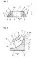
- FIG. 1 is a side sectional view showing a schematic configuration of an impeller manufactured by a method of manufacturing an impeller according to a first embodiment of the present invention.
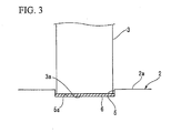
- FIG. 2 is a partially enlarged view showing an impeller in FIG. 1 .
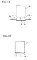
- FIG 3 is a schematic side view showing the impeller in FIG. 2 when seen from the outer peripheral side thereof.
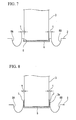
- FIG 4A is a view showing a state before brazing in an impeller manufacturing process.
- FIG. 4B is a view showing a state after the brazing in the impeller manufacturing process.
- the reference numeral 1 in FIG. 1 indicates an impeller manufactured by the method of manufacturing the impeller according to the first embodiment.
- the impeller is a rotary body which is assembled to a rotary shaft, and is mounted to a compressor such as a centrifugal compressor.
- the impeller 1 includes a substantially disk-shaped disk 2 which is coaxially attached to a rotary shaft (not shown), plural vane-shaped blades 3, each of which has one end fixed onto the disk 2 and which are radially disposed about the axis O of the rotary shaft, and a cover 4 which is disposed to face the disk 2 while being distant therefrom and is fixed to the other end of each blade 3.
- a space formed between a side surface of the blade 3 and a stream surface (surfaces facing each other) between the disk 2 and the cover 4 serves as a passageway R of a gas used to compress the compressor.
- the disk 2 is used to form the outer shape of the impeller 1, and is formed of metal such as carbon steel or stainless steel.
- the disk 2 includes a cylindrical portion 21 into which the rotary shaft (not shown) is fitted and a body portion 22 which extends from one end (that is, the lower side on FIGS. 1 and 2 ) of the cylindrical portion 21 in the rotary shaft direction Y toward the outer peripheral side in the radial direction X, where the cylindrical portion 21 and the body portion 22 are integrally formed with each other.
- the upper surface on the side of the passageway R of the gas
- the front surface 2a of the body portion 22 is formed in a curve shape which gradually protrudes toward a front end 21 a of the cylindrical portion 21 in the rotary shaft direction Y in a direction from the outer peripheral side to the inner peripheral side.
- the front surface 2a of the disk 2 is provided with a groove 5 which corresponds to an edge tip 3a of the blade 3 on the side of the disk 2, and has a thickness slightly larger than that of the blade 3.
- filler metal 6 such as powder or wire is disposed on a bottom portion 5a (groove inner surface) of the groove 5 so as to bond the blade 3 to the disk 2 by brazing.
- the depth of the groove 5 is, for example, equal to or more than 1 mm and equal to or less than 2 mm. In the case where the depth of the groove 5 becomes deeper, the amount of the filler metal 6 increases. For this reason, it is desirable that the depth of the groove 5 is shallow.
- Each blade 3 provided between the disk 2 and the cover 4 is smoothly curved so as to protrude toward the front end in the rotary shaft direction (the direction indicated by the arrow Y) as it becomes closer to the inner peripheral side in the radial direction (the direction indicated by the arrow X) along the front surface 2a of the disk 2, and is curved toward one side of the disk 2 in the circumferential direction.
- a lower surface 4a of the cover 4 is integrally fixed to a cover-side bonding end 3b of the blade 3, and the cover 4 is formed in a curve shape which protrudes toward the front end in the rotary shaft direction Y in a direction from the outer peripheral side to the inner peripheral side in the radial direction (the direction indicated by the arrow X).
- the passageway R is formed between the adjacent blades 3 so as to generate compressed air with the rotation of the impeller 1,
- the passageway R is formed in a curve shape in the rotary shaft direction Y and the circumferential direction along the shapes of the disk 2, the blade 3, and the cover 4.
- the air stream is generated, and the air is accelerated by the centrifugal force generated by the rotation, where the air stream is indicated by the arrow E facing from the inner peripheral side to the outer peripheral side in the radial direction in the passageway R. Accordingly, the air sucked into an inlet R1 of the passageway R is compressed inside the passageway R and is discharged from an outlet R2. Subsequently, the air is sent to an eternal device (not shown) on the downstream side.
- the groove 5 is formed in a blade attachment surface (front surface 2a) of the disk 2 so as to correspond to the shape of the blade 3, and as shown in FIG. 2 , the cover 4 is integrally formed with the plural blades 3 by cutting a material.
- the filler metal 6 being in a liquid state by heating is hardened inside the groove 5, and the edge tip 3a of the blade 3 is fitted to the groove 5. Accordingly, it is possible to strongly bond them to each other. Further, since the melted filler metal 6 does not flow outside from the groove 5 during the bonding operation, it is possible to prevent a problem of the amount of the filler metal 6 not being sufficient due to the outflow of the filler metal 6.
- the filler metal 6 melted by heating is disposed inside the groove 5 provided in the disk 2, the filler metal 6 being in a liquid state by heating is hardened inside the groove 5, and the edge tip 3 a of the blade 3 is tightly fitted and bonded to the groove 5, Accordingly, it is possible to reliably improve the bonding strength between the disk 2 and the blade 3.
- FIG. 5 is a schematic side view showing the impeller according to a first modified example of the first embodiment of the present invention when seen from the outer peripheral side thereof.
- the filler metal 6 is disposed in the bottom portion 5a (see FIG. 3 ) of the groove 5 in the first embodiment, but in the first modified example, instead of that position, the filler metals 6 are respectively disposed in both side surfaces (groove inner surfaces) 5b and 5b of the groove 5 formed in the disk 2.
- the groove 5 is formed in the disk 2 in advance, and the edge tip 3a of the blade 3 integrally formed with the cover 4 (see FIG. 2 ) is inserted into the groove 5, thereby bonding the disk 2 to the blade 3 through the filler metals 6.
- FIG. 6 is a schematic side view showing the impeller according to a second modified example of the first embodiment of the present invention when seen from the outer peripheral side thereof.
- filler metals (bonding agents) 7 are respectively disposed in even attachment corner portions 3c corresponding to the base portion of the blade 3 on the side of the disk 2. That is, in addition to the bonding inside the groove 5, the front surface 2a of the disk 2 forming the blade attachment surface in the vicinity of the groove 5 is bonded to the side surfaces of the blade 3 through the filler metals 7, thereby more reliably reinforcing the bonding portion between the blade 3 and the disk 2 applied with the largest stress during the rotation of the impeller.
- FIG. 7 is a schematic side view showing the impeller according to a third modified example of the first embodiment of the present invention when seen from the outer peripheral side thereof.
- FIG. 8 is a schematic side view showing the impeller according to a fourth modified example of the first embodiment of the present invention when seen from the outer peripheral side thereof.
- substantially semi-circular R grooves (recessed portions) 8A and 8B each having a circular-are surface in a sectional view are provided on both sides of the groove 5 of the disk 2 along the groove 5. Since the R grooves 8A and 8B are provided, it is possible to exhibit a function of alleviating stress concentration caused by the blade 3 during the rotation of the impeller.
- the diameter or depth of each circular-arc surface of the R grooves 8A and 8B is determined in accordance with the thickness of the disk 2.
- the reinforcing filler metals 7 respectively disposed on the attachment corner portions 3c of the blade 3 with respect to the disk 2 are smoothly and continuously distributed in the edge tips of the circumferential surfaces of the R grooves 8A and 8B, and the connection surface is formed as a continuous curve surface. Accordingly, it is possible to increase the advantage of reducing the stress concentration generated in the bonding portion during the rotation of the impeller.
- FIG. 9 is a schematic side view showing the impeller according to a second embodiment of the present invention when seen from the outer peripheral side thereof.
- the width D1 of a groove 5A formed in the disk 2 is set to be smaller than the width D2 of the blade 3, and a protruding portion 3d is formed in the disk edge tip 3a of the blade 3 so as to be fittable to the corresponding groove 5A.
- filler metals indicated by the reference numeral 6A is disposed in the bottom portion 5a of the groove 5A
- filler metals indicated by the reference numeral 6B are respectively disposed in groove edges.2c of the front surface 2a of the disk 2 located on both sides of the groove 5A. That is, the groove edges 2c of the disk 2 are respectively bonded to stepped surfaces 3e formed by the protruding portions 3d of the blade 3 through the filler metals 6B.
- FIG 10 is a schematic side view showing the impeller according to a modified example of the second embodiment when seen from the outer peripheral side thereof.
- the R grooves 8A and 8B according to the third and fourth modified examples are provided in the structure according to the second embodiment.
- the edge tips of the circular-arc surfaces of the R grooves 8A and 8B on the side of the blade 3 are respectively smoothly continuous to the side surfaces of the blade 3. Accordingly, it is possible to more effectively alleviate the stress concentration generated in the bonding portion between the disk 2 and the blade 3.
- the blade attachment surface as the front surface 2a of the disk 2 is provided with the groove 5, but the present invention is not limited thereto.
- the disk 2 and the blade 3 may be integrally formed in advance, the groove may be formed in the blade attachment surface of the cover 4 so as to correspond to the blade, and then the blade 3 integrally formed with the disk 2 may be inserted and bonded to the groove through the filler metal 6.
- the bonding operation is performed by the brazing, but the present invention is not limited thereto.
- liquid phase diffusion bonding may be used.
- the bonding method is used which disposes the filler metal 6 in the groove inner surface (the bottom portion 5a and the side surface 5b) on the side of the disk 2, and inserts and bonds the edge tip 3a of the blade to the groove 5, but the present invention is not limited thereto. That is, in the state where the filler metal 6 is disposed in the edge tip 3a of the blade without disposing the filler metal 6 in the groove 5, the edge tip 3a of the blade may be inserted and bonded to the groove 5.
- the shapes, sizes, and the like of the disk 2, the blade 3, and the cover 4 may be arbitrarily set. Further, the depth and width of the groove 5, the dimension of the R grooves 8A and 8B, and the like may be arbitrarily set depending on the conditions.
Landscapes
- Engineering & Computer Science (AREA)
- Mechanical Engineering (AREA)
- General Engineering & Computer Science (AREA)
- Structures Of Non-Positive Displacement Pumps (AREA)
Abstract
A method of manufacturing an impeller including a substantially disk-shaped disk, a cover facing the disk, and a blade provided between the disk and the cover, the method includes: forming a groove in a blade attachment surface of the disk or the cover so as to correspond to the shape of an edge tip of the blade; and bonding an inner surface of the groove to the edge tip of the blade through a bonding agent after inserting the edge tip of the blade into the groove.

Description
- The present invention relates to a method of manufacturing an impeller used in a centrifugal rotary machine such as a centrifugal compressor, an impeller, and a compressor having the impeller.
- Priority is claimed on Japanese Patent Application No.
2009-022867, filed February 3, 2009 - In the past, as an impeller used in a centrifugal rotary machine such as a centrifugal compressor, there has been known a cover attachment impeller (closed impeller) including a disk attached to a rotary shaft, a cover disposed in the disk while having a gap therebetween, and plural blades connecting the disk and the cover to each other. In the impeller, a portion surrounded by a side surface of each blade and stream surfaces of the cover and the disk is formed as a passageway used to compress air. In addition, the impeller provided in the centrifugal compressor is formed by, for example, integral forming performed by casting, machining, or electric spark machining, or bonding performed by welding, brazing, or liquid phase diffusion bonding after forging and mechanical machining.
- Among them, the integral forming is to integrally form the cover, the blade, and the disk by cutting a material. Incidentally, in general, the impeller provided in the centrifugal compressor includes a passageway formed in a complex shape in which the passageway is curved in the axial direction (rotary shaft direction) and the radial direction. For this reason, the integral forming is difficult.
- In the bonding performed by welding, two parts, that is, an integral member obtained by integrally forming the blade with one of the cover and the disk through cutting and the other of the cover and the disk, are bonded to each other through welding. Alternatively, the blade, the cover, and the disk are bonded to each other through welding. In this case, it is necessary to insert a welding torch inside the passageway. Accordingly, when the passageway is narrow, it is difficult to insert the welding torch into the passageway. As a result, welding defects may easily occur.
- Meanwhile, the bonding performed by brazing is known in, for example,
JP-A-2003-328989 JP-A-H07-109997 - In the method of manufacturing the impeller disclosed in Patent Document 1, a plating layer is provided both in the combination of a blade and a shroud (cover) and in a hab (disk). The hab provided with a groove having an R-part in both sides thereof and the combination is bonded to each other. Alternatively, a plating layer is provided both in the combination of the blade and the hab and the shroud. The shroud provided with a groove having an R-part in both sides thereof and the combination is bonded to each other.
- In the method of manufacturing the impeller disclosed in
Patent Document 2, a main-plate-side blade integrally formed with a hab (disk) and a shroud-side blade integrally formed with a shroud (cover) are bonded to each other through filler metal. - However, the method of manufacturing the impeller of the related art has the following problems.
- In the impeller provided in the centrifugal compressor, a tensile force is generated in a direction in which the cover and the disk move away from each other due to a centrifugal force with a rotation, and a relative bending stress is generated in the rotation direction. Accordingly, a large stress concentration is generated in a bonding portion corresponding to a joint between the blade and the disk. For this reason, in the case of the bonding performed by brazing, in order to reduce the stress concentration, it is necessary to consider a solution such that the brazing portion is formed in a fillet shape. However, as described above, each passageway R is formed in a complex curve shape, and the bonding line between the blade and either the disk or the cover is formed as a complex three-dimensional curve. Accordingly, the melted filler metal may flow outside during the brazing. That is, in this case, the amount of the filler metal may be not sufficient in a part of the bonding portion, or the filler metal may be lost, which may cause bonding defects. Accordingly, it is not possible to ensure sufficient bonding strength. For this reason, in the bonding performed by brazing, liquid phase diffusion bonding, or the like, there is a demand for a method capable of reliably improving the bonding strength.
- The present invention is contrived in consideration of the above-described problem, and an object of the present invention is to provide a method of manufacturing an impeller capable of improving the bonding strength between a blade and either a disk or a cover, an impeller having a high bonding strength between a blade and either a disk or a cover, and a compressor having an impeller.
- In order to achieve the above-described object, according to an aspect of the present invention, there is provided a method of manufacturing an impeller including a substantially disk-shaped disk, a cover facing the disk, a blade provided between the disk and the cover, the method including: forming a groove in a blade attachment surface of the disk or the cover so as to correspond to the shape of an edge tip of the blade; and bonding an inner surface of the groove to the edge tip of the blade through a bonding agent after inserting the edge tip of the blade into the groove.
- According to another aspect of the present invention, there is provided an impeller including: a substantially disk-shaped disk; a cover facing the disk; and a blade provided between the disk and the cover, wherein the blade is inserted into a groove formed in at least one of the disk and the cover, and is bonded thereto through use of a bonding agent.
- With the above-described configuration, the groove is provided in the blade attachment surface of the disk or the cover so as to correspond to the shape of the edge tip of the blade, the bonding agent such as filler metal is disposed in the groove or the bonding-side edge tip of the blade, and then the edge tip of the blade is inserted into the groove by heating the bonding agent so as to bond to each other through use of a melted bonding agent. At this time, the bonding agent being in a liquid state due to heating is hardened inside the groove, and the edge tip of the blade is strongly fitted and bonded to the groove. In addition, since it is possible to prevent the melted bonding agent from flowing outside during the bonding operation, it is possible to prevent a problem such that the amount of the bonding material is not sufficient in the bonding portion.
- The method having the above-described configuration may further include: disposing a bonding agent so as to bond a side surface of the blade to the blade attachment surface in the vicinity of the groove.
- In this case, in addition to the bonding inside the groove, the side surface of the blade and the blade attachment surface are bonded to each other. Accordingly, it is possible to more reliably reinforce the bonding portion between the disk or the cover and the blade applied with large stress.
- In the impeller having the above-described configuration, substantially semi-circular recessed portions each having a circular-arc surface in a sectional view may be provided on both sides of the groove along the groove.
- In this case, it is possible to alleviate the stress concentration generated in the bonding portion between the blade and either the cover or the disk during the rotation of the impeller. Particularly, since the edge tip of the groove is close to the side surface of the blade so as to be smoothly continuous thereto, it is possible to increase the advantage of reducing the stress concentration.
- In the method of manufacturing the impeller and in an impeller having the above-described configuration, the bonding agent melted by heating is disposed inside the groove provided in the disk or the cover, and the bonding agent being in a liquid state by heating is hardened inside the groove so that the edge tip of the blade is tightly fitted and bonded to the groove. Accordingly, it is possible to reliably improve the bonding strength between the blade and either the cover or the disk.
- The compressor according to still another aspect of the present invention includes an impeller having a high bonding strength between the blade and the disk or the cover manufactured by the method of manufacturing the impeller according to an aspect of the present invention.
-
-
FIG 1 is a side sectional view showing a schematic configuration of an impeller manufactured by a method of manufacturing an impeller according to a first embodiment of the present invention. -
FIG. 2 is a partially enlarged view showing an impeller inFIG. 1 . -
FIG. 3 is a schematic side view showing the impeller inFIG. 2 when seen from the outer peripheral side thereof. -
FIG. 4A is a view showing a state before brazing in an impeller manufacturing process. -
FIG. 4B is a view showing a state after the brazing in the impeller manufacturing process. -
FIG. 5 is a schematic side view showing the impeller according to a first modified example of the first embodiment of the present invention when seen from the outer peripheral side thereof. -
FIG. 6 is a schematic side view showing the impeller according to a second modified example of the first embodiment of the present invention when seen from the outer peripheral side thereof. -
FIG. 7 is a schematic side view showing the impeller according to a third modified example of the first embodiment of the present invention when seen from the outer peripheral side thereof. -
FIG. 8 is a schematic side view showing the impeller according to a fourth modified example of the first embodiment of the present invention when seen from the outer peripheral side thereof. -
FIG. 9 is a schematic side view showing the impeller according to a second embodiment of the present invention when seen from the outer peripheral side thereof. -
FIG. 10 is a schematic side view showing the impeller according to a modified example of the second embodiment when seen from the outer peripheral side thereof. - Hereinafter, a method of manufacturing an impeller and an impeller according to a first embodiment of the present invention will be described with reference to
FIGS. 1 to 4A and 4B . -
FIG. 1 is a side sectional view showing a schematic configuration of an impeller manufactured by a method of manufacturing an impeller according to a first embodiment of the present invention.FIG. 2 is a partially enlarged view showing an impeller inFIG. 1 .FIG 3 is a schematic side view showing the impeller inFIG. 2 when seen from the outer peripheral side thereof.FIG 4A is a view showing a state before brazing in an impeller manufacturing process.FIG. 4B is a view showing a state after the brazing in the impeller manufacturing process. - The reference numeral 1 in
FIG. 1 indicates an impeller manufactured by the method of manufacturing the impeller according to the first embodiment. The impeller is a rotary body which is assembled to a rotary shaft, and is mounted to a compressor such as a centrifugal compressor. - As shown in
FIGS. 1 and 2 , the impeller 1 includes a substantially disk-shapeddisk 2 which is coaxially attached to a rotary shaft (not shown), plural vane-shapedblades 3, each of which has one end fixed onto thedisk 2 and which are radially disposed about the axis O of the rotary shaft, and a cover 4 which is disposed to face thedisk 2 while being distant therefrom and is fixed to the other end of eachblade 3. In addition, a space formed between a side surface of theblade 3 and a stream surface (surfaces facing each other) between thedisk 2 and the cover 4 serves as a passageway R of a gas used to compress the compressor. - The right side on
FIG. 2 is set to the inner peripheral side (the side of the axis O shown inFIG. 1 ) of the impeller 1, and the left side is set to the outer peripheral side. InFIGS. 1 and 2 , in a gas flowing direction (a direction indicated by the arrow E) inside the passageway R, the upper side is set to the upstream side, and the lower side is set to the downstream side. The rotary shaft direction of the impeller 1 is set to the Y direction, and the radial direction thereof is set to the X direction. Hereinafter, the directions will be consistently used. - The
disk 2 is used to form the outer shape of the impeller 1, and is formed of metal such as carbon steel or stainless steel. Thedisk 2 includes acylindrical portion 21 into which the rotary shaft (not shown) is fitted and abody portion 22 which extends from one end (that is, the lower side onFIGS. 1 and 2 ) of thecylindrical portion 21 in the rotary shaft direction Y toward the outer peripheral side in the radial direction X, where thecylindrical portion 21 and thebody portion 22 are integrally formed with each other. Here, it will be described hereinafter on the assumption that the upper surface (on the side of the passageway R of the gas), facing the cover 4, of thedisk 2 shown inFIGS. 1 and 2 is set to afront surface 2a, and the opposite lower surface thereof is set to arear surface 2b. Thefront surface 2a of thebody portion 22 is formed in a curve shape which gradually protrudes toward afront end 21 a of thecylindrical portion 21 in the rotary shaft direction Y in a direction from the outer peripheral side to the inner peripheral side. - As shown in
FIGS. 2 and3 , thefront surface 2a of thedisk 2 is provided with agroove 5 which corresponds to anedge tip 3a of theblade 3 on the side of thedisk 2, and has a thickness slightly larger than that of theblade 3. In addition, in this embodiment, filler metal 6 (bonding agent) such as powder or wire is disposed on abottom portion 5a (groove inner surface) of thegroove 5 so as to bond theblade 3 to thedisk 2 by brazing. In addition, the depth of thegroove 5 is, for example, equal to or more than 1 mm and equal to or less than 2 mm. In the case where the depth of thegroove 5 becomes deeper, the amount of thefiller metal 6 increases. For this reason, it is desirable that the depth of thegroove 5 is shallow. - Each
blade 3 provided between thedisk 2 and the cover 4 is smoothly curved so as to protrude toward the front end in the rotary shaft direction (the direction indicated by the arrow Y) as it becomes closer to the inner peripheral side in the radial direction (the direction indicated by the arrow X) along thefront surface 2a of thedisk 2, and is curved toward one side of thedisk 2 in the circumferential direction. - A
lower surface 4a of the cover 4 is integrally fixed to a cover-side bonding end 3b of theblade 3, and the cover 4 is formed in a curve shape which protrudes toward the front end in the rotary shaft direction Y in a direction from the outer peripheral side to the inner peripheral side in the radial direction (the direction indicated by the arrow X). - That is, as described above, the passageway R is formed between the
adjacent blades 3 so as to generate compressed air with the rotation of the impeller 1, The passageway R is formed in a curve shape in the rotary shaft direction Y and the circumferential direction along the shapes of thedisk 2, theblade 3, and the cover 4. - In the case where the impeller 1 of the compressor having the above-described configuration is rotationally driven about the axis O by a driving unit (not shown), the air stream is generated, and the air is accelerated by the centrifugal force generated by the rotation, where the air stream is indicated by the arrow E facing from the inner peripheral side to the outer peripheral side in the radial direction in the passageway R. Accordingly, the air sucked into an inlet R1 of the passageway R is compressed inside the passageway R and is discharged from an outlet R2. Subsequently, the air is sent to an eternal device (not shown) on the downstream side.
- Next, the method of manufacturing the impeller 1 will be described. First, as shown in
FIG. 4A , thegroove 5 is formed in a blade attachment surface (front surface 2a) of thedisk 2 so as to correspond to the shape of theblade 3, and as shown inFIG. 2 , the cover 4 is integrally formed with theplural blades 3 by cutting a material. - Subsequently, the
filler metal 6 is disposed throughout thebottom portion 5a of thegroove 5, and as shown inFIG. 4B , theedge tip 3 a of theblade 3 is inserted into thegroove 5 so that the inner surface of thegroove 5 is bonded to theedge tip 3a of theblade 3 through thefiller metal 6. In detail, when thefiller metal 6 interposed between theblade 3 and thegroove 5 of thedisk 2 is heated while applying, for example, a compressing force thereto, thefiller metal 6 is melted, and the liquid-state filler metal 6 is uniformly distributed throughout the gap between thegroove 5 and theblade 3, thereby bonding thedisk 2 to theblade 3. That is, since thegroove 5 is provided, thefiller metal 6 being in a liquid state by heating is hardened inside thegroove 5, and theedge tip 3a of theblade 3 is fitted to thegroove 5. Accordingly, it is possible to strongly bond them to each other. Further, since the meltedfiller metal 6 does not flow outside from thegroove 5 during the bonding operation, it is possible to prevent a problem of the amount of thefiller metal 6 not being sufficient due to the outflow of thefiller metal 6. - In the method of manufacturing the impeller and the compressor according to the first embodiment, since the
filler metal 6 melted by heating is disposed inside thegroove 5 provided in thedisk 2, thefiller metal 6 being in a liquid state by heating is hardened inside thegroove 5, and theedge tip 3 a of theblade 3 is tightly fitted and bonded to thegroove 5, Accordingly, it is possible to reliably improve the bonding strength between thedisk 2 and theblade 3. - Next, another embodiment and modified examples will be described with reference to the accompanying drawings. Since the same reference numerals will be given to the same constituents as those of the first embodiment, the description thereof will be omitted, and a configuration different from that of the first embodiment will be described.
-
FIG. 5 is a schematic side view showing the impeller according to a first modified example of the first embodiment of the present invention when seen from the outer peripheral side thereof. - As shown in
FIG. 5 , thefiller metal 6 is disposed in thebottom portion 5a (seeFIG. 3 ) of thegroove 5 in the first embodiment, but in the first modified example, instead of that position, thefiller metals 6 are respectively disposed in both side surfaces (groove inner surfaces) 5b and 5b of thegroove 5 formed in thedisk 2. Even in this case, as in the first embodiment, thegroove 5 is formed in thedisk 2 in advance, and theedge tip 3a of theblade 3 integrally formed with the cover 4 (seeFIG. 2 ) is inserted into thegroove 5, thereby bonding thedisk 2 to theblade 3 through thefiller metals 6. -
FIG. 6 is a schematic side view showing the impeller according to a second modified example of the first embodiment of the present invention when seen from the outer peripheral side thereof. - As shown in
FIG. 6 , in the second modified example, in the state where theblade 3 is inserted into thegroove 5 having the filler metal 6a disposed in thebottom portion 5a, filler metals (bonding agents) 7 are respectively disposed in evenattachment corner portions 3c corresponding to the base portion of theblade 3 on the side of thedisk 2. That is, in addition to the bonding inside thegroove 5, thefront surface 2a of thedisk 2 forming the blade attachment surface in the vicinity of thegroove 5 is bonded to the side surfaces of theblade 3 through thefiller metals 7, thereby more reliably reinforcing the bonding portion between theblade 3 and thedisk 2 applied with the largest stress during the rotation of the impeller. -
FIG. 7 is a schematic side view showing the impeller according to a third modified example of the first embodiment of the present invention when seen from the outer peripheral side thereof.FIG. 8 is a schematic side view showing the impeller according to a fourth modified example of the first embodiment of the present invention when seen from the outer peripheral side thereof. - In the third modified example shown in
FIG. 7 , substantially semi-circular R grooves (recessed portions) 8A and 8B each having a circular-are surface in a sectional view are provided on both sides of thegroove 5 of thedisk 2 along thegroove 5. Since theR grooves blade 3 during the rotation of the impeller. The diameter or depth of each circular-arc surface of theR grooves disk 2. In addition, it is desirable that the advantage of the stress alleviation function becomes larger as the distance t between each of theR grooves blade 3 fitted to thegroove 5 becomes smaller. - That is, as in the fourth modified example in
FIG. 8 , when the distance t becomes minimal, the reinforcingfiller metals 7 respectively disposed on theattachment corner portions 3c of theblade 3 with respect to thedisk 2 are smoothly and continuously distributed in the edge tips of the circumferential surfaces of theR grooves -
FIG. 9 is a schematic side view showing the impeller according to a second embodiment of the present invention when seen from the outer peripheral side thereof. - In the second embodiment shown in
FIG. 9 , the width D1 of agroove 5A formed in thedisk 2 is set to be smaller than the width D2 of theblade 3, and a protrudingportion 3d is formed in thedisk edge tip 3a of theblade 3 so as to be fittable to thecorresponding groove 5A. In addition, filler metals indicated by thereference numeral 6A is disposed in thebottom portion 5a of thegroove 5A, and filler metals indicated by thereference numeral 6B are respectively disposed in groove edges.2c of thefront surface 2a of thedisk 2 located on both sides of thegroove 5A. That is, the groove edges 2c of thedisk 2 are respectively bonded to steppedsurfaces 3e formed by the protrudingportions 3d of theblade 3 through thefiller metals 6B. -
FIG 10 is a schematic side view showing the impeller according to a modified example of the second embodiment when seen from the outer peripheral side thereof. - In the modified example (fifth modified example) of the second embodiment shown in
FIG. 10 , theR grooves R grooves blade 3 are respectively smoothly continuous to the side surfaces of theblade 3. Accordingly, it is possible to more effectively alleviate the stress concentration generated in the bonding portion between thedisk 2 and theblade 3. - As described above, although the method of manufacturing the impeller and the impeller according to the first and second embodiments and the first to fifth modified examples of the present invention are described, the present invention is not limited to the above-described embodiments and modified examples, but may be appropriately modified within the scope without departing from the spirit of the present invention.
- For example, in the above-described embodiments and modified examples, the blade attachment surface as the
front surface 2a of thedisk 2 is provided with thegroove 5, but the present invention is not limited thereto. For example, thedisk 2 and theblade 3 may be integrally formed in advance, the groove may be formed in the blade attachment surface of the cover 4 so as to correspond to the blade, and then theblade 3 integrally formed with thedisk 2 may be inserted and bonded to the groove through thefiller metal 6. - In the above-described embodiments and modified examples, the bonding operation is performed by the brazing, but the present invention is not limited thereto. For example, liquid phase diffusion bonding may be used.
- In the above-described embodiments and modified examples, the bonding method is used which disposes the
filler metal 6 in the groove inner surface (thebottom portion 5a and theside surface 5b) on the side of thedisk 2, and inserts and bonds theedge tip 3a of the blade to thegroove 5, but the present invention is not limited thereto. That is, in the state where thefiller metal 6 is disposed in theedge tip 3a of the blade without disposing thefiller metal 6 in thegroove 5, theedge tip 3a of the blade may be inserted and bonded to thegroove 5. - In addition, the shapes, sizes, and the like of the
disk 2, theblade 3, and the cover 4 may be arbitrarily set. Further, the depth and width of thegroove 5, the dimension of theR grooves - While preferred embodiments of the present invention have been described and illustrated above, it should be understood that these are exemplary of the present invention and are not to be considered as limiting. Additions, omissions, substitutions, and other modifications can be made without departing from the spirit or scope of the present invention. Accordingly, the present invention is not to be considered as being limited by the foregoing description, and is only limited by the scope of the appended claims.
Claims (5)
- A method of manufacturing an impeller including a substantially disk-shaped disk, a cover facing the disk, and a blade provided between the disk and the cover, the method comprising:forming a groove in a blade attachment surface of the disk or the cover so as to correspond to the shape of an edge tip of the blade; andbonding an inner surface of the groove to the edge tip of the blade through a bonding agent after inserting the edge tip of the blade into the groove.
- The method according to claim 1, further comprising:disposing a bonding agent so as to bond a side surface of the blade to the blade attachment surface in the vicinity of the groove.
- An impeller comprising:a substantially disk-shaped disk;a cover facing the disk; anda blade provided between the disk and the cover,wherein the blade is inserted into a groove formed in at least one of the disk and the cover, and is bonded thereto through use of a bonding agent.
- The impeller according to claim 3,
wherein substantially semi-circular recessed portions each having a circular-arc surface in a sectional view are provided on both sides of the groove along the groove. - A compressor comprising the impeller according to claim 3 or 4.
Applications Claiming Priority (1)
| Application Number | Priority Date | Filing Date | Title |
|---|---|---|---|
| JP2009022867A JP2010180721A (en) | 2009-02-03 | 2009-02-03 | Method of manufacturing impeller, and compressor |
Publications (1)
| Publication Number | Publication Date |
|---|---|
| EP2213881A2 true EP2213881A2 (en) | 2010-08-04 |
Family
ID=41716344
Family Applications (1)
| Application Number | Title | Priority Date | Filing Date |
|---|---|---|---|
| EP10000979A Withdrawn EP2213881A2 (en) | 2009-02-03 | 2010-02-01 | Method of manufacturing impeller, impeller, and compressor having impeller |
Country Status (3)
| Country | Link |
|---|---|
| US (1) | US20100196163A1 (en) |
| EP (1) | EP2213881A2 (en) |
| JP (1) | JP2010180721A (en) |
Cited By (3)
| Publication number | Priority date | Publication date | Assignee | Title |
|---|---|---|---|---|
| CN102625881A (en) * | 2010-11-11 | 2012-08-01 | 三菱重工业株式会社 | Method for manufacturing impeller |
| WO2016046036A1 (en) * | 2014-09-22 | 2016-03-31 | Siemens Aktiengesellschaft | Radial compressor impeller and associated radial compressor |
| CN110315298A (en) * | 2019-07-26 | 2019-10-11 | 湖南南方通用航空发动机有限公司 | A kind of processing method of integral blade disk |
Families Citing this family (10)
| Publication number | Priority date | Publication date | Assignee | Title |
|---|---|---|---|---|
| EP2679333B1 (en) | 2011-02-22 | 2019-05-08 | Mitsubishi Heavy Industries Compressor Corporation | Method of manufacturing impeller |
| US20140030099A1 (en) * | 2012-07-27 | 2014-01-30 | GM Global Technology Operations LLC | Pump impeller |
| FR2998920B1 (en) * | 2012-12-04 | 2018-07-27 | Thy Engineering | ROTATING MACHINE SUCH AS A TURBINE OR A COMPRESSOR. |
| KR101465052B1 (en) * | 2013-04-12 | 2014-11-25 | 두산중공업 주식회사 | Shrouds of centrifugal compressor impeller and method of manufacturing the same |
| JP6850607B2 (en) * | 2014-05-26 | 2021-03-31 | ヌオーヴォ ピニォーネ ソチエタ レスポンサビリタ リミタータNuovo Pignone S.R.L. | Methods for Manufacturing Turbomachinery Components |
| JP6490527B2 (en) * | 2015-07-22 | 2019-03-27 | 住友重機械エンバイロメント株式会社 | Crushing blade for water treatment |
| JP6297529B2 (en) * | 2015-10-22 | 2018-03-20 | ミネベアミツミ株式会社 | Impeller, method for manufacturing the impeller, and centrifugal fan including the impeller |
| EP3399195B1 (en) * | 2015-12-28 | 2020-02-19 | Daikin Industries, Ltd. | Method and apparatus for manufacturing an impeller of a centrifugal fan |
| CN105965218B (en) * | 2016-04-29 | 2018-06-05 | 沈阳透平机械股份有限公司 | Supercharger impeller metamorphic layer removes the method for inspection and its device |
| JP6982267B2 (en) * | 2020-05-08 | 2021-12-17 | ダイキン工業株式会社 | Closed impeller and manufacturing method of closed impeller |
Citations (3)
| Publication number | Priority date | Publication date | Assignee | Title |
|---|---|---|---|---|
| JPH07109997A (en) | 1993-10-14 | 1995-04-25 | Mitsubishi Heavy Ind Ltd | Impeller for fluid machinery and its manufacture |
| JP2003328989A (en) | 2002-05-16 | 2003-11-19 | Hitachi Industries Co Ltd | How to make an impeller |
| JP2009022867A (en) | 2007-07-19 | 2009-02-05 | Nordson Corp | Slot nozzle assembly, slot coating gun, shim plate, and method of extruding foamable melted material in wide band |
Family Cites Families (7)
| Publication number | Priority date | Publication date | Assignee | Title |
|---|---|---|---|---|
| DE2049679A1 (en) * | 1970-10-09 | 1972-04-13 | Bosch Gmbh Robert | Fan for an electric machine |
| JPS53109208A (en) * | 1977-03-04 | 1978-09-22 | Hitachi Ltd | Manufacturing process of brazed runner |
| JPS59196901A (en) * | 1983-04-25 | 1984-11-08 | Ebara Corp | Sealed impeller made of ceramics |
| JPH05202701A (en) * | 1992-01-28 | 1993-08-10 | Mitsubishi Heavy Ind Ltd | Joining method |
| FR2776030B1 (en) * | 1998-03-11 | 2000-07-13 | Abb Solyvent Ventec | CENTRIFUGAL VENTILATION WHEEL IN COMPOSITE MATERIALS |
| JP2002364588A (en) * | 2001-06-05 | 2002-12-18 | Hitachi Ltd | Impeller and method of manufacturing the same |
| US7762778B2 (en) * | 2007-05-17 | 2010-07-27 | Kurz-Kasch, Inc. | Fan impeller |
-
2009
- 2009-02-03 JP JP2009022867A patent/JP2010180721A/en active Pending
-
2010
- 2010-01-29 US US12/696,452 patent/US20100196163A1/en not_active Abandoned
- 2010-02-01 EP EP10000979A patent/EP2213881A2/en not_active Withdrawn
Patent Citations (3)
| Publication number | Priority date | Publication date | Assignee | Title |
|---|---|---|---|---|
| JPH07109997A (en) | 1993-10-14 | 1995-04-25 | Mitsubishi Heavy Ind Ltd | Impeller for fluid machinery and its manufacture |
| JP2003328989A (en) | 2002-05-16 | 2003-11-19 | Hitachi Industries Co Ltd | How to make an impeller |
| JP2009022867A (en) | 2007-07-19 | 2009-02-05 | Nordson Corp | Slot nozzle assembly, slot coating gun, shim plate, and method of extruding foamable melted material in wide band |
Cited By (5)
| Publication number | Priority date | Publication date | Assignee | Title |
|---|---|---|---|---|
| CN102625881A (en) * | 2010-11-11 | 2012-08-01 | 三菱重工业株式会社 | Method for manufacturing impeller |
| CN102625881B (en) * | 2010-11-11 | 2015-04-01 | 三菱重工业株式会社 | Method for manufacturing impeller |
| WO2016046036A1 (en) * | 2014-09-22 | 2016-03-31 | Siemens Aktiengesellschaft | Radial compressor impeller and associated radial compressor |
| CN106715920A (en) * | 2014-09-22 | 2017-05-24 | 西门子公司 | Radial compressor impeller and associated radial compressor |
| CN110315298A (en) * | 2019-07-26 | 2019-10-11 | 湖南南方通用航空发动机有限公司 | A kind of processing method of integral blade disk |
Also Published As
| Publication number | Publication date |
|---|---|
| US20100196163A1 (en) | 2010-08-05 |
| JP2010180721A (en) | 2010-08-19 |
Similar Documents
| Publication | Publication Date | Title |
|---|---|---|
| US20100196163A1 (en) | Method of manufacturing impeller, impeller, and compressor having impeller | |
| EP2216119A1 (en) | Manufacturing method of impeller | |
| EP2051832B1 (en) | A method of friction welding | |
| JP5837927B2 (en) | Solid phase resistance welding to repair and fabricate airfoils | |
| CN103097739A (en) | Impeller, rotary machine with impeller, and method for manufacturing impeller | |
| JP6298808B2 (en) | Method for forming a metal reinforcement with an insert for protecting a composite leading edge | |
| CN115485479B (en) | Closed impeller and manufacturing method of closed impeller | |
| EP2390023B1 (en) | Method of manufacturing member for reinforcing front edge of fan blade | |
| JP5535878B2 (en) | Impeller manufacturing method | |
| EP2392422A1 (en) | Method of manufacturing member for reinforcing front edge of fan blade | |
| JP2008240584A (en) | Weld groove sealing structure and welding method thereof | |
| CN102203428B (en) | The manufacture method of impeller, compressor and impeller | |
| JP2005325839A (en) | Friction stir welded hollow airfoil and method therefor | |
| EP2281653A1 (en) | A method of friction welding a first workpiece to a second workpiece with converging parts | |
| EP2679826A1 (en) | Impeller, rotor comprising same, and impeller manufacturing method | |
| US20140064975A1 (en) | Impeller and rotary machine provided with the same | |
| JP2003505634A (en) | Seal ring for non-hermetic fluid seal | |
| JP2009275513A (en) | Impeller, compressor using impeller and method for manufacturing impeller | |
| KR101444849B1 (en) | Method of manufacturing rotation part of rotary machine | |
| JP6202731B2 (en) | Assembly method of impeller | |
| KR100730026B1 (en) | Rotor part coupling structure of vacuum pump | |
| CN106437864A (en) | Rotating component for a turbomachine and method for providing cooling of a rotating component | |
| JP2005163607A (en) | Vane type vacuum pump and method for manufacturing rotor and coupling for vacuum pump | |
| JP5033689B2 (en) | Ceramic member and connection structure of ceramic member | |
| CN103079750A (en) | Method for welding metallic blades |
Legal Events
| Date | Code | Title | Description |
|---|---|---|---|
| PUAI | Public reference made under article 153(3) epc to a published international application that has entered the european phase |
Free format text: ORIGINAL CODE: 0009012 |
|
| 17P | Request for examination filed |
Effective date: 20100201 |
|
| AK | Designated contracting states |
Kind code of ref document: A2 Designated state(s): AT BE BG CH CY CZ DE DK EE ES FI FR GB GR HR HU IE IS IT LI LT LU LV MC MK MT NL NO PL PT RO SE SI SK SM TR |
|
| AX | Request for extension of the european patent |
Extension state: AL BA RS |
|
| STAA | Information on the status of an ep patent application or granted ep patent |
Free format text: STATUS: THE APPLICATION IS DEEMED TO BE WITHDRAWN |
|
| 18D | Application deemed to be withdrawn |
Effective date: 20120901 |