EP2213699A1 - Method for inserting carbon particles into a polyurethane surface layer - Google Patents
Method for inserting carbon particles into a polyurethane surface layer Download PDFInfo
- Publication number
- EP2213699A1 EP2213699A1 EP09001308A EP09001308A EP2213699A1 EP 2213699 A1 EP2213699 A1 EP 2213699A1 EP 09001308 A EP09001308 A EP 09001308A EP 09001308 A EP09001308 A EP 09001308A EP 2213699 A1 EP2213699 A1 EP 2213699A1
- Authority
- EP
- European Patent Office
- Prior art keywords
- polyurethane
- carbon particles
- surface layer
- carbon
- solution
- Prior art date
- Legal status (The legal status is an assumption and is not a legal conclusion. Google has not performed a legal analysis and makes no representation as to the accuracy of the status listed.)
- Withdrawn
Links
Images


Classifications
-
- C—CHEMISTRY; METALLURGY
- C08—ORGANIC MACROMOLECULAR COMPOUNDS; THEIR PREPARATION OR CHEMICAL WORKING-UP; COMPOSITIONS BASED THEREON
- C08J—WORKING-UP; GENERAL PROCESSES OF COMPOUNDING; AFTER-TREATMENT NOT COVERED BY SUBCLASSES C08B, C08C, C08F, C08G or C08H
- C08J7/00—Chemical treatment or coating of shaped articles made of macromolecular substances
- C08J7/02—Chemical treatment or coating of shaped articles made of macromolecular substances with solvents, e.g. swelling agents
-
- B—PERFORMING OPERATIONS; TRANSPORTING
- B32—LAYERED PRODUCTS
- B32B—LAYERED PRODUCTS, i.e. PRODUCTS BUILT-UP OF STRATA OF FLAT OR NON-FLAT, e.g. CELLULAR OR HONEYCOMB, FORM
- B32B27/00—Layered products comprising a layer of synthetic resin
- B32B27/40—Layered products comprising a layer of synthetic resin comprising polyurethanes
-
- B—PERFORMING OPERATIONS; TRANSPORTING
- B82—NANOTECHNOLOGY
- B82Y—SPECIFIC USES OR APPLICATIONS OF NANOSTRUCTURES; MEASUREMENT OR ANALYSIS OF NANOSTRUCTURES; MANUFACTURE OR TREATMENT OF NANOSTRUCTURES
- B82Y30/00—Nanotechnology for materials or surface science, e.g. nanocomposites
-
- C—CHEMISTRY; METALLURGY
- C08—ORGANIC MACROMOLECULAR COMPOUNDS; THEIR PREPARATION OR CHEMICAL WORKING-UP; COMPOSITIONS BASED THEREON
- C08K—Use of inorganic or non-macromolecular organic substances as compounding ingredients
- C08K3/00—Use of inorganic substances as compounding ingredients
- C08K3/02—Elements
- C08K3/04—Carbon
-
- C—CHEMISTRY; METALLURGY
- C08—ORGANIC MACROMOLECULAR COMPOUNDS; THEIR PREPARATION OR CHEMICAL WORKING-UP; COMPOSITIONS BASED THEREON
- C08L—COMPOSITIONS OF MACROMOLECULAR COMPOUNDS
- C08L75/00—Compositions of polyureas or polyurethanes; Compositions of derivatives of such polymers
- C08L75/04—Polyurethanes
-
- B—PERFORMING OPERATIONS; TRANSPORTING
- B32—LAYERED PRODUCTS
- B32B—LAYERED PRODUCTS, i.e. PRODUCTS BUILT-UP OF STRATA OF FLAT OR NON-FLAT, e.g. CELLULAR OR HONEYCOMB, FORM
- B32B2313/00—Elements other than metals
- B32B2313/04—Carbon
-
- C—CHEMISTRY; METALLURGY
- C08—ORGANIC MACROMOLECULAR COMPOUNDS; THEIR PREPARATION OR CHEMICAL WORKING-UP; COMPOSITIONS BASED THEREON
- C08J—WORKING-UP; GENERAL PROCESSES OF COMPOUNDING; AFTER-TREATMENT NOT COVERED BY SUBCLASSES C08B, C08C, C08F, C08G or C08H
- C08J2375/00—Characterised by the use of polyureas or polyurethanes; Derivatives of such polymers
- C08J2375/04—Polyurethanes
-
- C—CHEMISTRY; METALLURGY
- C08—ORGANIC MACROMOLECULAR COMPOUNDS; THEIR PREPARATION OR CHEMICAL WORKING-UP; COMPOSITIONS BASED THEREON
- C08K—Use of inorganic or non-macromolecular organic substances as compounding ingredients
- C08K2201/00—Specific properties of additives
- C08K2201/001—Conductive additives
-
- Y—GENERAL TAGGING OF NEW TECHNOLOGICAL DEVELOPMENTS; GENERAL TAGGING OF CROSS-SECTIONAL TECHNOLOGIES SPANNING OVER SEVERAL SECTIONS OF THE IPC; TECHNICAL SUBJECTS COVERED BY FORMER USPC CROSS-REFERENCE ART COLLECTIONS [XRACs] AND DIGESTS
- Y10—TECHNICAL SUBJECTS COVERED BY FORMER USPC
- Y10T—TECHNICAL SUBJECTS COVERED BY FORMER US CLASSIFICATION
- Y10T428/00—Stock material or miscellaneous articles
- Y10T428/24—Structurally defined web or sheet [e.g., overall dimension, etc.]
- Y10T428/24355—Continuous and nonuniform or irregular surface on layer or component [e.g., roofing, etc.]
- Y10T428/24372—Particulate matter
Definitions
- the present invention relates to a method for introducing electrically conductive carbon particles into a surface layer comprising polyurethane. These carbon particles may in particular be carbon nanotubes. It further relates to a polyurethane layer which comprises electrically conductive carbon particles and is obtainable by a method according to the invention. The invention further relates to a polyurethane article having a surface layer comprising an electrically conductive carbon particle obtainable by a method according to the invention.
- Carbon nanotubes are known for their exceptional properties. For example, their strength is about 100 times that of steel, their thermal conductivity is about twice that of diamond, their thermal stability reaches up to 2800 ° C in vacuum and their electrical conductivity can be many times the conductivity of copper , However, these structural characteristics are only accessible at the molecular level if it is possible to homogeneously distribute carbon nanotubes and to produce the largest possible contact between the tubes and the medium, ie to make them compatible with the medium and thus stable dispersible. With regard to electrical conductivity, it is furthermore necessary to form a homogeneous network of tubes, in which they ideally only touch at the ends.
- the carbon nanotubes should be as isolated as possible, that is agglomerate-free, not aligned and present in a concentration at which such a network can just form, which is reflected by the sudden increase in electrical conductivity as a function of the concentration of carbon nanotubes (percolation limit) ,
- carbon nanotubes in the form of bundles and / or agglomerates find an energetic minimum, their compatibility with the surrounding medium must be increased.
- a chemical Although covalent functionalization of carbon nanotubes can improve their compatibility with the medium. This manifests itself for example in an increased (thermal) long-term stability and the absence of reagglomeration during, for example, polyurethane production.
- this surface modification also interrupts the delocalized ⁇ -electron system of the tube and thus lowers the electrical conductivity of each individual tube as a function of the degree of functionalization.
- non-covalent functionalization of carbon nanotubes by, for example, dispersing additives provides an alternative to the chemical, covalent modification and compatibilization of the tube with the medium.
- dispersing additives provides an alternative to the chemical, covalent modification and compatibilization of the tube with the medium.
- this approach will require one requires new optimization with regard to the chemistry and the concentration of the respective dispersing additive and can never represent a universal solution.
- any processing of fillers including carbon nanotubes
- a new property such as electrical conductivity
- degrading several other mechanical properties This is especially critical when carbon nanotubes are incorporated into unfoamed, compact and / or elastic systems.
- Residual agglomerates which could not be completely broken up during the dispersion process represent, for example, a predetermined breaking point in a compact molded part. Mechanical properties such as, for example, the impact strength and breaking strength are impaired by such agglomerates.
- carbon nanotubes would have to be distributed homogeneously over the entire volume of the material so that the percolation limit is exceeded and at the same time no residual agglomerates are present.
- Fugetsu et al. (Carbon 2008, ASAP, doi: 10.1016 / j.carbon.2008.11.013 ) establish a process in which polyester fibers are passed through a dip bath and coated on the surface with CNTs.
- multi-walled carbon nanotubes in aqueous solution were first dispersed by means of surfactants and then mixed with an anionic polyurethane dispersion.
- the dip bath temperature was 40 ° C.
- the dipped fiber was then heated in an oven at 170 ° C (100 ° C above the glass transition temperature of the polyester fiber) for 30 seconds.
- fibers modified in this way had electrical conductivities in the area of interest for antistatic applications even after washing with water.
- Electrically conductive particles in the meaning of the present invention are initially all particles of a material which is not an insulator.
- insulators are substances which have an electrical conductivity of less than 10 -8 S / m.
- the particles are incorporated in a surface layer comprising polyurethane, which means that it is not only the surface itself that is occupied by the particles, but also that the material lying directly below the surface absorbs the particles.
- the term surface layer as opposed to the two-dimensional surface, means a three-dimensional layer of material which includes the surface as one of its boundaries. The surface layer is delimited to the interior of the object in question at least by the fact that it contains just the electrically conductive particles.
- the polyurethane (PUR) itself may initially be any polyurethane and may contain the usual additives such as fillers, flame retardants and the like.
- polyurethane classes are PU foams including foamed polyurethanes with a very high density of more than 600 kg / m 3 , PUR casting resins, PUR cast elastomers and thermoplastic PUR (TPU).
- the surface layer is associated with a molded part or semifinished product such as foils, tubes or sheets comprising a polyurethane.
- the polyurethane is thus generally not present as a polymer dispersion.
- Step (A) involves providing a solution of unaggregated carbon particles.
- a solution of unaggregated carbon particles This means that the particles in the solvent are isolated or at least so little aggregated that the solution is stable.
- a stable solution in this case occurs in a storage at room temperature for a period of at least one day, preferably a week or four weeks, no flocculation or precipitation of the carbon particles.
- the existing aggregates of the carbon particles through Energy input, for example by means of ultrasound, grinding processes or high shear forces are broken.
- the solvent is selected after that it can both form the solution of the carbon particles and swell the polyurethane surface.
- the average particle diameter may also be in a range from ⁇ 1 nm to ⁇ 1000 nm or from ⁇ 3 nm to ⁇ 100 nm.
- the determination can be made for example by means of scanning electron microscopy or dynamic light scattering.
- the solvent may be an aqueous or a nonaqueous solvent. In the latter case, it is preferably a polar, aprotic solvent. In this way, the solvent can interact well with the soft segment domains in the polyurethane.
- nonaqueous means that no additional water has been added to the solvent, but excludes the technically unavoidable traces of water, for example, up to an amount of ⁇ 5% by weight, preferably ⁇ 3% by weight, and more preferably ⁇ 1% by weight. , not ans.
- the carbon particles may be deagglomerated in solution by addition of surfactants or other surfactants and kept in solution.
- the carbon particles may be contained in the solvent in a concentration of, for example, ⁇ 0.01% by weight to ⁇ 20% by weight, ⁇ 0.1% by weight to ⁇ 15% by weight, or ⁇ 1% by weight to ⁇ 10% by weight. available.
- step (B) The contacting of the polyurethane-comprising surface layer with the solution of the carbon particles in step (B) naturally takes place over the surface of the polyurethane.
- the solution of the carbon particles acts on the surface layer.
- the solvent swells at least the soft segment domains in the polyurethane, forms pores in the surface layer, and allows carbon particles to migrate into these pores.
- the swelling of the soft segment domains is favored if there are long polyether segments with a small number of carbon atoms between the ether bridges in the polyurethane. Such domains are hydrophilic enough to swell.
- the particles may, for example, penetrate into the surface layer to a depth of ⁇ 150 nm, ⁇ 100 nm or ⁇ 50 nm.
- the exposure time is chosen such that the polyurethane of the surface layer is not converted into solution.
- the process according to the invention is not a process in which the polymer is first dissolved homogeneously and then, together with nanoparticles, the finished particles are obtained in the matrix by removing the solvent.
- the exposure time is chosen so that swelling of the polymer surface can take place. Examples of suitable exposure times are ⁇ 1 minute to ⁇ 360 minutes, preferably ⁇ 10 minutes to ⁇ 90 minutes, more preferably ⁇ 3 minutes to ⁇ 5 minutes.
- step (D) involves stopping the action of the solution of the carbon particles on the surface layer.
- the solution of the carbon particles is separated from the surface layer again.
- the surface layer can be rinsed to remove adherent solution. This can be done, inter alia, by removing the polyurethane article with the surface layer to be modified from a dipping bath. Thereafter, the article can be rinsed with acetone, for example.
- step (D) is followed by a drying step of removing the solvent in the swollen surface layer, closing the pores in the polyurethane and entrapping the carbon particles in the polymer.
- the method according to the invention thus offers the possibility of selectively providing the surface layer of a polyurethane article with electrically conductive particles.
- the shape of the object is not destroyed by dissolution, so that even finished moldings can be treated. Since the particles are concentrated in the near-surface area of the article, a smaller total amount is needed to obtain an electrically conductive polyurethane surface.
- no large amounts of solvents need to be removed to obtain the final modified polymer. It is also possible to keep the concentration of the carbon particles in a range in which no technically disadvantageous increase in viscosity occurs.
- An advantageous application of the method according to the invention is the treatment of polyurethane moldings, which are then to be painted by an electrostatic powder coating or to be galvanized.
- the electrically conductive particles in the surface layer provide for an improved electrostatic powder application.
- Another application relates to the treatment of polyurethane moldings for the preparation of an electrodeposition coating. It is also possible to obtain conductive electrode materials or elastic polyurethane capacitors. Furthermore, electronic components or cable sheathing can be provided with an antistatic coating.
- the action takes place the solution of the carbon particles on the polyurethane-comprising surface layer using ultrasound and / or heat instead.
- the energy input by ultrasound and / or heat on the one hand counteracts the formation of particle clusters and thus allows higher particle concentrations in the solution.
- the introduction of the particles into the polyurethane surface layer is accelerated.
- the frequency is advantageously 20 kHz to ⁇ 20 MHz and, independently of this, the power density in the solvent is ⁇ 1 W / l to ⁇ 200 W / l.
- the temperature may be ⁇ 30 ° C to ⁇ 200 ° C, preferably ⁇ 40 ° C to ⁇ 150 ° C.
- the carbon particles are not covalently functionalized on their surface.
- the particles do not carry any additional functional groups covalently attached via further reaction steps on their surface.
- oxidizing agents such as nitric acid, hydrogen peroxide, potassium permanganate and sulfuric acid or a possible mixture of these agents for the functionalization of the carbon particles is avoided.
- An advantage of the use of non-covalently functionalized particles is that the ⁇ -electron system of the surface is not disturbed and therefore can contribute fully to the electrical conductivity.
- the carbon particles are selected from the group consisting of carbon nanotubes, single-walled carbon nanotubes, multi-walled carbon nanotubes, carbon nanohormers, carbon nano-onions, fullerenes, graphite, graphene, carbon fibers and / or conductive carbon black , In addition to increasing the electrical conductivity, these particles can also improve mechanical properties of the surface layer, such as elasticity and impact strength.
- Carbon nanotubes in the sense of the invention are all single-walled or multi-walled carbon nanotubes of the cylinder-type, scroll-type, multiscroll-type or onion-like structure. Preference is given to using multi-walled carbon nanotubes of the cylinder type, scroll type, multiscroll type or mixtures thereof. It is favorable if the carbon nanotubes have a ratio of length to outer diameter of ⁇ 5, preferably ⁇ 100.
- the individual graphene or graphite layers in these carbon nanotubes seen in cross-section, evidently run continuously from the center of the carbon nanotubes to the outer edge without interruption. This may, for example, allow for improved and faster intercalation of other materials in the tube framework as more open edges than the entry zone of the intercalates are available compared to single-scroll carbon nanotubes ( Carbon 1996, 34, 1301-3 ) or CNTs with onion-like structure ( Science 1994, 263, 1744-7 ).
- the carbon particles are non-covalently functionalized, multi-walled carbon nanotubes with a diameter of ⁇ 3 nm to ⁇ 100 nm.
- the diameter here refers to the mean diameter of the nanotubes. It can also be in a range from ⁇ 5 nm to ⁇ 80 nm and advantageously from ⁇ 6 nm to ⁇ 60 nm.
- the length of the nanotubes is initially not limited. However, it can be, for example, in a range of ⁇ 1 ⁇ m to ⁇ 100 ⁇ m and advantageously of ⁇ 10 ⁇ m to ⁇ 30 ⁇ m.
- the polyurethane is obtainable from the reaction of polyisocyanates with polyester polyols and / or polyether polyols.
- Preferred polyisocyanates are those based on diphenylmethane diisocyanate (MDI) and toluene diisocyanate (TDI).
- MDI diphenylmethane diisocyanate
- TDI toluene diisocyanate
- Preferred polyester polyols and polyether polyols have hydroxyl numbers of ⁇ 100 mg KOH / g to ⁇ 150 mg KOH / g.
- Preferred polyols may furthermore have molar masses in the range from ⁇ 250 to ⁇ 5000 g / mol, preferably ⁇ 400 to ⁇ 3500 g / mol, a functionality between ⁇ 1.8 and ⁇ 6, preferably between ⁇ 1.95 and ⁇ 3.5.
- polyurethanes which are obtainable from prepolymers of the starting compounds mentioned with subsequent chain extension.
- the solvent is selected from the group comprising methanol, ethanol, isopropanol, butanol, ethylene glycol, propylene glycol, butylene glycol, glycerol, hydroquinone, acetone, ethyl acetate, trichlorethylene, trichloroethane, trichloromethane, methylene chloride, cyclohexanone, N, N Dimethylformamide, dimethylsulfoxide, tetrahydrofuran, N-methyl-2-pyrrolidone, benzene, toluene, chlorobenzene, styrene, polyesterpolyols, polyetherpolyols, mixtures of the abovementioned solvents with one another and / or mixtures of the abovementioned solvents with water.
- the surface layer comprising polyurethane is contacted with the solution of the carbon particles by immersion, application, printing, brushing, spraying and / or pouring.
- immersion, application, printing, brushing, spraying and / or pouring By immersing in an immersion bath, for example, objects can be easily completely treated. Also, a continuous process for producing a thus treated polymer film can be easily realized.
- the printing of polyurethane articles for example by screen printing, allows the presentation of electrically conductive structures such as printed conductors on the polyurethane article.
- a further subject of the present invention is a polyurethane layer comprising electrically conductive carbon particles and obtainable by a method according to the invention, wherein the outer surface of the polyurethane layer comprises elevations and depressions with an average height of the elevations of ⁇ 50 nm to ⁇ 500 nm and an average distance between adjacent elevations of ⁇ 0.5 ⁇ m to ⁇ 1.5 ⁇ m.
- the height of the elevation is calculated from the vertical distance of the highest point of a survey to the lowest point of an adjacent depression. Figuratively speaking, this corresponds to the distance from Wellenberg to Wellental.
- the distance between adjacent elevations is then visually the distance between two peaks. In cross section, this may result in a frayed image.
- the surface of the polyurethane layer may, for example, be in the form of a network of elongate elevations and the corresponding valley-shaped depressions.
- the average height of the elevations it may also be in a range from ⁇ 100 nm to ⁇ 400 nm or from ⁇ 150 nm to ⁇ 300 nm.
- the average distance between adjacent elevations may also be in a range from ⁇ 0.7 ⁇ m to ⁇ 1.2 ⁇ m or from ⁇ 0.9 ⁇ m to ⁇ 1.0 ⁇ m.
- the solution with the carbon particles causes swelling of the polyurethane segment structure at the contact surface, which, depending on the polarity of the solution used, leads from swelling of the soft segments to swelling of the hard segments.
- Subsequent evaporation of the solution thus leads to an altered morphology of the polyurethane soft and hard segments on the surface as a result of the greasing of the carbon particles. In the atomic force microscope image, this can be identified, for example, as undulating elevations and depressions.
- the polyurethane layer may, for example, have a surface resistivity of ⁇ 1 ohm to ⁇ 10 megohm.
- the specific surface resistance can be determined by the DIN IEC 60093 (12) .93 standard.
- this resistance is in a range of ⁇ 10 ohms to ⁇ 1000000 ohms, more preferably from ⁇ 100 olun to ⁇ 100000 ohms.
- the present invention also relates to a polyurethane article having a surface layer comprising electrically conductive carbon particles obtainable by a process according to the invention, the carbon layers being present in the polyurethane to a depth of ⁇ 1 ⁇ m below the surface.
- the surface layer comprises polyurethane.
- the particles in this surface layer form a network, so that an electrical conductivity occurs.
- the particles may also be present to a depth of ⁇ 500 nm or ⁇ 150 nm below the surface.
- articles which comprise the polyurethane surface layer provided with carbon particles and additionally comprise further materials It may, for example, be commodities which at least partially comprise a polyurethane surface and in which surface or polyurethane surface layer, the electrically conductive carbon particles were introduced.
- Exemplary of the mentioned polyurethane articles are called polyurethane moldings, which are then to be painted by an electrostatic powder coating or electrocoating or to be galvanized.
- Other examples include conductive and conductive and elastic electrode materials, generally electronic components or cable sheathing with an antistatic coating.
- the carbon particles are present within the polyurethane material of the surface layer comprising them in a proportion of ⁇ 0.1% by weight to ⁇ 5% by weight.
- the proportion may also be in a range from ⁇ 0.5% by weight to ⁇ 4% by weight or from ⁇ 1% by weight to ⁇ 5% by weight. Ultimately, therefore, this indicates the content of carbon particles in the surface layer.
- the boundary of the surface layer inside the article, from which the polyurethane material is no longer included in the calculation, is formed by the lowest (innermost) line to which the carbon particles in the polyurethane occur. Within the ranges given, the percolation limit for the carbon particles can be exceeded so that the electrical conductivity key is greatly improved.
- the surface layer comprising the carbon particles has a surface resistivity of ⁇ 1 ohm to ⁇ 10 megohm.
- the specific surface resistance is based on the DIN IEC standard Determine 60093 (12) .93.
- this resistance is in a range of ⁇ 10 ohms to ⁇ 1000000 ohms, more preferably 100 ohms to ⁇ 100000 ohms.
- the carbon particles are unfunctionalized, multi-walled carbon nanotubes with a diameter of ⁇ 3 nm to ⁇ 100 nm.
- the diameter here refers to the mean diameter of the nanotubes. It can also be in a range from ⁇ 5 nm to ⁇ 80 nm and advantageously from ⁇ 6 run to ⁇ 60 nm.
- the length of the nanotubes is initially not limited. However, it can be, for example, in a range of ⁇ 1 ⁇ m to ⁇ 100 ⁇ m and advantageously of ⁇ 10 ⁇ m to ⁇ 30 ⁇ m.
- the polyurethane article comprises a first and a second electroconductive carbon particle-containing surface layer, said first and second surface layers being opposed to each other and separated by a polyurethane layer. Due to the manufacturing process, the first and second surface layers are integrally bonded to the separating, electrically insulating polyurethane layer. By such a structure of two dielectric layers separated by a dielectric, an elastic capacitor can be realized.
- this is present as a composite of a carrier material with the polyurethane surface layer comprising electrically conductive carbon particles.
- support materials are ceramics, metals, but also other polymers such as polycarbonates or polyolefins.
- a metal molding can first be coated with polyurethane and then the polyurethane surface layer can be provided with the carbon particles.
- polyol Polyether polyol having an OH number of 112 mg KOH / mg and a viscosity of 140 mPa ⁇ s at 25 ° C.
- Catalyst Dibutyltin dilaurate (0.02% by weight), DABCO 33-LV® (0.54% by weight, Air Products) isocyanate: DESMODUR® CD-S: modified isocyanate based on diphenylmethane-4,4'-diisocyanate having an NCO content of 29.0 to 30.0% by weight and a viscosity of 20 to 50 mPa ⁇ s at 25 ° C.
- carbon Multi-walled carbon nanotubes (BAYTUBES® C 150 P)
- Dipping solution Dispersion of BAYTUBES® C 150 P in a solvent
- the aforementioned components polyol, catalyst and isocyanate were mixed together at room temperature so that the ratio was 105.
- the dipping solution was prepared by sonicating the carbon particles in the ultrasonic bath and used immediately. To functionalize the polyurethane surface, the samples were completely immersed in the solution, rinsed briefly after removal with acetone and freed at elevated temperature of excess solvent.
- a sample of a polyurethane elastomer (7 x 7 x 0.2 cm) was completely immersed in a solution of 1% by weight of BAYTUBES® C 150 P in N-methyl-2-pyrrolidone.
- the exposure time was 0.5 h under sonication in an ultrasonic bath and additionally 5.5 h without sonication at room temperature.
- the sample was rinsed briefly with acetone and freed of solvents at 100 ° C. in a drying oven.
- the measured surface resistivity ranged from 10 2 to 10 4 ohms. Closer examination by AFM revealed the incorporation of the nanotubes into the polyurethane surface to a penetration depth of approximately 0.5 ⁇ m ( FIG. 3 ).
- Corresponding conductivity measurements (TUNA) also showed conductivity at the PU surface ( FIG. 2 ).
- a specimen of a polyurethane elastomer (7 ⁇ 7 ⁇ 0.2 cm) was completely immersed in an ultrasound bath in a solution of 0.5% by weight of BAYTUBES® C 150 P in acetone dipped.
- the exposure time was 1 h, the temperature of the dipping solution was 45 ° C.
- the sample was rinsed briefly with acetone and freed of solvent at 50 ° C. in a drying oven.
- the measured surface resistivity was in the range of 10 5 ohms.
- a sample of a polyurethane elastomer (7 x 7 x 0.2 cm) was immersed in a solution of 0.5% by weight of BAYTUBES® C 150 P in acetone. The exposure time was 1 h, the temperature of the dipping solution was 23 ° C. The sample was rinsed briefly with acetone and freed of solvent at 50 ° C. in a drying oven. The measured surface resistivity was in the range of 10 6 ohms.
- FIG. 1 schematically shows a polyurethane article according to the invention with three-layer structure.
- carbon nanotubes were introduced into the top (1) and bottom (2) surface layers of the polyurethane. These nanotubes are represented by dashes or dots in the respective layers (1, 2). It can be seen that the nanotubes have a limited penetration depth into the surface layers.
- the surface layers are separated by a nanotube-free polyurethane layer (3). Due to the manufacturing process of the polyurethane article is still in one piece with respect to the surface layers (1, 2) constructed and the surface layers are materially connected to the nanotube-free layer (3).
- the polyurethane article shown may, with suitable dimensions, serve, for example, as a film-shaped condenser.
- a sample of the polyurethane article obtained in Example 1 was examined by atomic force microscope (AFM) imaging.
- Information on the presence and location of carbon nanotubes is provided by Tunnel AFM (TUNA) in FIG. 2 , This is a sample cross-section.
- the width of the displayed image section was 10 ⁇ m.
- the left part of the image contains matrix material into which the sample has been enclosed in order to prepare the cross sections.
- In the right part is the unchanged polyurethane material.
- the surface layer interspersed with the tunnel-current-conducting carbon nanotubes.
- FIG. 3 and 4 show different image sections of the same sample in cross-sectional view and in the phase-sensitive mode.
- the width of the displayed image section was 2.5 ⁇ m.
- the left-hand part of the images contains matrix material into which the sample was enclosed in order to prepare the cross-sections.
- the right part is the unchanged polyurethane material.
- the surface layer penetrated by carbon nanotubes passes.
- the phase sensitive recording in FIG. 3 and 4 leave in the Surface layer embedded carbon nanotubes clearly visible as bright lines. Overall, it is thus shown that the nanotubes are also present below the surface of the polyurethane.
- FIG. 5 shows a further cross-sectional view with a width of the image section of 5 microns.
- the embedded in the surface layer carbon nanotubes can be seen as well visible bright lines.
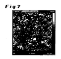
- FIG. 6 and 7 Images of a top view of the sample surface are in FIG. 6 and 7 shown.
- the height in FIG. 6 shows a structure pervaded by elevations and valley-shaped depressions.
- the width of the displayed image section was 2.5 ⁇ m.
- the corresponding phase sensitive view in FIG. 7 show on the sample surface accessible carbon nanotubes as bright lines.
Abstract
Description
Die vorliegende Erfindung betrifft ein Verfahren zum Einbringen von elektrisch leitfähigen Kohlenstoffteilchen in eine Polyurethan umfassende Oberflächenschicht. Diese Kohlenstoffteilchen können insbesondere Kohlenstoff-Nanoröhren sein. Sie betrifft weiterhin eine Polyurethan-Schicht, welche elektrisch leitfähige Kohlenstoffteilchen umfasst und durch ein erfindungsgemäßes Verfahren erhältlich ist. Weiterhin betrifft die Erfindung einen Polyurethan-Gegenstand mit einer durch ein erfindungsgemäßes Verfahren erhältlichen, elektrisch leitfähige Kohlenstoffteilchen umfassenden Oberflächenschicht.The present invention relates to a method for introducing electrically conductive carbon particles into a surface layer comprising polyurethane. These carbon particles may in particular be carbon nanotubes. It further relates to a polyurethane layer which comprises electrically conductive carbon particles and is obtainable by a method according to the invention. The invention further relates to a polyurethane article having a surface layer comprising an electrically conductive carbon particle obtainable by a method according to the invention.
Kohlenstoffnanoröhren (carbon nanotubes, CNTs) sind für ihre außergewöhnlichen Eigenschaften bekannt. So beträgt beispielsweise deren Festigkeit das ungefähr 100-fache des Stahls, deren thermische Leitfähigkeit ist etwa doppelt so groß wie die von Diamant, ihre thermische Stabilität reicht bis hoch zu 2800 °C im Vakuum und deren elektrische Leitfähigkeit kann ein Vielfaches der Leitfähigkeit von Kupfer betragen. Diese strukturbedingten Charakteristika sind auf molekularer Ebene allerdings nur dann zugänglich, wenn es gelingt, Kohlenstoffnanoröhren homogen zu verteilen und einen möglichst großen Kontakt zwischen den Röhren und dem Medium herzustellen, also diese mit dem Medium verträglich und somit stabil dispergierbar zu machen. Hinsichtlich elektrischer Leitfähigkeit ist es weiterhin erforderlich, ein homogenes Netzwerk an Röhren auszubilden, in dem sich diese im Idealfall nur an den Enden berühren. Hierbei sollten die Kohlenstoffnanoröhren möglichst vereinzelt, das heißt agglomeratfrei, nicht ausgerichtet und in einer Konzentration vorliegen, bei der sich ein solches Netzwerk gerade eben ausbilden kann, was sich durch den sprunghaften Anstieg der elektrischen Leitfähigkeit in Abhängigkeit von der Konzentration an Kohlenstofmanoröhren widerspiegelt (Perkolationsgrenze).Carbon nanotubes (CNTs) are known for their exceptional properties. For example, their strength is about 100 times that of steel, their thermal conductivity is about twice that of diamond, their thermal stability reaches up to 2800 ° C in vacuum and their electrical conductivity can be many times the conductivity of copper , However, these structural characteristics are only accessible at the molecular level if it is possible to homogeneously distribute carbon nanotubes and to produce the largest possible contact between the tubes and the medium, ie to make them compatible with the medium and thus stable dispersible. With regard to electrical conductivity, it is furthermore necessary to form a homogeneous network of tubes, in which they ideally only touch at the ends. Here, the carbon nanotubes should be as isolated as possible, that is agglomerate-free, not aligned and present in a concentration at which such a network can just form, which is reflected by the sudden increase in electrical conductivity as a function of the concentration of carbon nanotubes (percolation limit) ,
Für technische Anwendungen ist daher die Einarbeitung von solchen Partikeln in Polymermatrices interessant. Zwei Aspekte müssen für eine erfolgreiche Verarbeitung von Kohlenstoffhanoröhren, wenn man durch ihre Nutzung einen Werkstoff beispielsweise elektrisch leitfähig machen möchte, berücksichtigt werden: das vollständige Aufbrechen und Entbilndeln von Kohlenstoffnanoröhren-Agglomeraten und die Unterdrückung der großen Neigung von Kohlenstoffnanoröhren zur Reagglomeration (in ein und demselben Medium während des Alterungsprozesses oder während der Verarbeitung einer solchen Dispersion zum fertigen Werkstoff). Diese Schwierigkeiten bei der Kohlenstoffnanoröhren-Verarbeitung fußen auf den hydrophoben Charakter der Kohlenstoffnanoröhren-Oberfläche und das hohe Aspektverhältnis dieser quasi eindimensionalen Struktur.For technical applications, therefore, the incorporation of such particles in polymer matrices is of interest. Two aspects have to be taken into account for the successful processing of carbon nanotubes, for example, when one wants to make a material electrically conductive by their use: the complete breaking up and deconvolution of carbon nanotube agglomerates and the suppression of the great tendency of carbon nanotubes to reagglomeration (in one and the same Medium during the aging process or during the processing of such a dispersion to the finished material). These difficulties in carbon nanotube processing are due to the hydrophobic nature of the carbon nanotube surface and the high aspect ratio of this quasi one-dimensional structure.
Soll nun vermieden werden, dass Kohlenstoffnanoröhren in der Form von Bündeln und/oder Agglomerate ein energetisches Minimum finden, muss ihre Verträglichkeit mit dem sie umgebenden Medium erhöht werden. Hierbei ist allerdings zu beachten, dass eine chemische, kovalente Funktionalisierung von Kohlenstoffnanoröhren ihre Verträglichkeit mit dem Medium zwar verbessern kann. Dies äußert sich zum Beispiel in einer erhöhten (thermischen) Langzeitstabilität und dem Ausbleiben von Reagglomeration während beispielsweise der Polyurethan-Herstellung. Allerdings wird durch diese Oberflächenmodifikation auch das delokalisierte π-Elektronensystem der Röhre unterbrochen und somit die elektrische Leitfähigkeit jeder einzelnen Röhre in Abhängigkeit des Funktionalisierungsgrades erniedrigt.If it is now to be avoided that carbon nanotubes in the form of bundles and / or agglomerates find an energetic minimum, their compatibility with the surrounding medium must be increased. However, it should be noted that a chemical, Although covalent functionalization of carbon nanotubes can improve their compatibility with the medium. This manifests itself for example in an increased (thermal) long-term stability and the absence of reagglomeration during, for example, polyurethane production. However, this surface modification also interrupts the delocalized π-electron system of the tube and thus lowers the electrical conductivity of each individual tube as a function of the degree of functionalization.
Die nicht kovalente Funktionalisierung von Kohlenstoffnanoröhren durch beispielsweise Dispergieradditive stellt eine Alternative zur chemischen, kovalenten Modifikation und Verträglichmachung der Röhre mit dem Medium dar. Allerdings muss hierbei beachtet werden, dass dieser Ansatz für jedes neue Medium, egal ob Polyurethan-Rohstoff oder -Formulierung, einer neuen Optimierung hinsichtlich der Chemie und der Konzentration des jeweiligen Dispergieradditivs bedarf und niemals eine Universallösung darstellen kann.The non-covalent functionalization of carbon nanotubes by, for example, dispersing additives provides an alternative to the chemical, covalent modification and compatibilization of the tube with the medium. However, it should be noted that for any new medium, whether polyurethane raw material or formulation, this approach will require one requires new optimization with regard to the chemistry and the concentration of the respective dispersing additive and can never represent a universal solution.
Zuletzt gilt zu beachten, dass jede Verarbeitung von Füllstoffen, so auch von Kohlenstoffnanoröhren, auch Risiken in der Hinsicht birgt, dass möglicherweise eine neue Eigenschaft, beispielsweise die elektrische Leitfähigkeit, erzielt werden kann, gleichzeitig allerdings mehrere andere mechanische Eigenschaften verschlechtert werden können. Dies ist vor allem dann kritisch, wenn Kohlenstoffnanoröhren in ungeschäumte, kompakte und/oder elastische Systeme eingearbeitet werden. Restagglomerate, die während des Dispergierprozesses nicht vollständig aufgebrochen werden konnten, stellen beispielsweise in einem kompakten Formteil eine Sollbruchstelle dar. Mechanische Eigenschaften wie zum Beispiel die Schlagzähigkeit und Bruchfestigkeit werden durch solche Agglomerate verschlechtert. Mit der Absicht nun, einen kompakten Werkstoff durch den Zusatz von Kohlenstoffnanoröhren elektrisch leitfähig zu machen, müssten nach dem bisherigen Stand der Technik über das gesamte Volumen des Werkstoffes Kohlenstoffnanoröhren homogen verteilt sein, sodass die Perkolationsgrenze überschritten wird und gleichzeitig keine Restagglomerate mehr vorliegen.Finally, it should be noted that any processing of fillers, including carbon nanotubes, also carries risks in that it may be possible to achieve a new property, such as electrical conductivity, while at the same time degrading several other mechanical properties. This is especially critical when carbon nanotubes are incorporated into unfoamed, compact and / or elastic systems. Residual agglomerates which could not be completely broken up during the dispersion process represent, for example, a predetermined breaking point in a compact molded part. Mechanical properties such as, for example, the impact strength and breaking strength are impaired by such agglomerates. With the intention of making a compact material electrically conductive by the addition of carbon nanotubes, according to the prior art, carbon nanotubes would have to be distributed homogeneously over the entire volume of the material so that the percolation limit is exceeded and at the same time no residual agglomerates are present.
Diese Vorgehensweise scheitert sehr oft bereits an den dramatischen Viskositätsanstiegen, welche durch die hierfür erforderlichen Kohlenstoffnanoröhren-Konzentrationen zum Überschreiten der Perkolationsgrenze bedingt sind. Des Weiteren kann die Reagglomeration von homogen dispergierten Kohlenstoffnanoröhren während der Polyurethan-Verarbeitung mit dieser Methode nicht ausgeschlossen und ohne Weiteres verhindert werden.This procedure very often fails already due to the dramatic increases in viscosity, which are due to the carbon nanotubes concentrations required for exceeding the percolation limit. Furthermore, the reagglomeration of homogeneously dispersed carbon nanotubes during polyurethane processing can not be excluded with this method and easily prevented.
Im Zusammenhang mit der Verarbeitung von Kohlenstoffnanoröhren in (thermoplastischen) Polyurethanen sind zahlreiche Arbeiten literaturbekannt, bei denen das fertige Polymer zuerst vollständig in einem organischen Lösungsmittel aufgelöst wird, anschließend die Nanoröhren-Dispergierung in dieser Polymerlösung erfolgt und die so erhaltene Nanoröhren-Dispersion auf Polyurethan/Lösungsmittelbasis zu einem Film gezogen oder in eine Form gegossen wird. Der letzte Schritt ist bei diesen Verfahren jeweils die langwierige Verdampfung der großen Mengen an Lösungsmittel. Beispiele hierfür finden sich in den folgenden Veröffentlichungen:
Eine Übersicht über dieses Gebiet findet sich auch in
Des Weiteren sind Prozesse literaturbekannt (
Eine mögliche Alternative stellt der Ansatz dar, nicht die gesamte Polymermatrix, sondern nur eine unmittelbar an die Oberfläche angrenzende Materialschicht mit den Partikeln auszustatten. Wünschenswert wäre ein solches Vorgehen, um die eingangs beschriebenen Nachteile des Lösungsmittelverbrauchs und des Viskositätsanstiegs zu vermeiden.A possible alternative is the approach not to equip the entire polymer matrix, but only with a directly adjacent to the surface material layer with the particles. Such an approach would be desirable to avoid the disadvantages of solvent consumption and viscosity increase described above.
Erfindungsgemäß vorgeschlagen wird daher ein Verfahren zum Einbringen von elektrisch leitfähigen Teilchen in eine Polyurethan umfassende Oberflächenschicht, umfassend die Schritte:
- (A) Bereitstellen einer Lösung von nicht aggregierten Kohlenstoffteilchen mit einem mittleren Teilchendurchmesser von ≥ 0,3 nm bis ≤ 3000 nm in einem Lösungsmittel, welches in der Lage ist, das Aufquellen einer Polyurethan umfassenden Oberflächenschicht zu bewirken;
- (B) Kontaktieren der Polyurethan umfassenden Oberflächenschicht mit der Lösung der Kohlenstoffteilchen;
- (C) Einwirken der Lösung der Kohlenstoffteilchen auf die Polyurethan umfassende Oberflächenschicht für eine Zeitdauer, welche nicht ausreicht, um das Polyurethan in Lösung zu überführen;
- (D) Beenden des Einwirkens der Lösung der Kohlenstoffteilchen auf die Polyurethan umfassende Oberflächenschicht.
- (A) providing a solution of non-aggregated carbon particles having an average particle diameter of ≥ 0.3 nm to ≤ 3000 nm in a solvent capable of causing the swelling of a surface layer comprising polyurethane;
- (B) contacting the surface layer comprising polyurethane with the solution of carbon particles;
- (C) exposing the carbon particles to the polyurethane-containing surface layer for a period of time insufficient to dissolve the polyurethane;
- (D) terminating the action of the solution of the carbon particles on the surface layer comprising polyurethane.
Elektrisch leitfähige Teilchen im Sinne der vorliegenden Erfindung sind zunächst alle Teilchen aus einem Material, welches kein Isolator ist. Typischerweise werden als Isolatoren Substanzen bezeichnet, welche eine elektrische Leitfähigkeit von weniger als 10-8 S/m aufweisen. Die Teilchen werden in eine Polyurethan umfassende Oberflächenschicht eingebracht, was bedeutet, dass nicht unbedingt nur die Oberfläche selbst mit den Teilchen belegt wird, sondern auch das unmittelbar unterhalb der Oberfläche liegende Material die Teilchen aufnimmt. Demzufolge bedeutet im Rahmen der Erfindung der Begriff der Oberflächenschicht, im Gegensatz zur zweidimensionalen Oberfläche, eine dreidimensionale Materialschicht, welche die Oberfläche als eine ihrer Begrenzungen mit einschließt. Die Oberflächenschicht wird zum Inneren des betreffenden Gegenstands zumindest dadurch abgegrenzt, dass sie eben die elektrisch leitfähigen Partikel enthält.Electrically conductive particles in the meaning of the present invention are initially all particles of a material which is not an insulator. Typically, insulators are substances which have an electrical conductivity of less than 10 -8 S / m. The particles are incorporated in a surface layer comprising polyurethane, which means that it is not only the surface itself that is occupied by the particles, but also that the material lying directly below the surface absorbs the particles. Accordingly, in the context of the invention, the term surface layer, as opposed to the two-dimensional surface, means a three-dimensional layer of material which includes the surface as one of its boundaries. The surface layer is delimited to the interior of the object in question at least by the fact that it contains just the electrically conductive particles.
Das Polyurethan (PUR) selbst kann zunächst jedes beliebige Polyurethan sein und die üblichen Zusätze wie Füllstoffe, Flammschutzmittel und dergleichen enthalten. Beispiele für Polyurethanklassen sind PUR-Schäume einschließlich geschäumter Polyurethane mit sehr hoher Rohdichte von über 600 kg/m3, PUR-Gießharze, PUR-Gießelastomere und thermoplastische PUR (TPU).The polyurethane (PUR) itself may initially be any polyurethane and may contain the usual additives such as fillers, flame retardants and the like. Examples of polyurethane classes are PU foams including foamed polyurethanes with a very high density of more than 600 kg / m 3 , PUR casting resins, PUR cast elastomers and thermoplastic PUR (TPU).
Es ist möglich und bevorzugt, dass die Oberflächenschicht zu einem Polyurethan umfassenden Formteil oder Halbzeug wie Folien, Röhren oder Platten zugehörig ist. Das Polyurethan liegt generell also nicht als Polymerdispersion vor.It is possible and preferred that the surface layer is associated with a molded part or semifinished product such as foils, tubes or sheets comprising a polyurethane. The polyurethane is thus generally not present as a polymer dispersion.
Schritt (A) beinhaltet das Bereitstellen einer Lösung von nicht aggregierten Kohlenstoffteilchen. Dieses bedeutet, dass die Teilchen in dem Lösungsmittel vereinzelt vorliegen oder zumindest so wenig aggregiert sind, dass die Lösung stabil ist. In einer stabilen Lösung tritt hierbei in einer Lagerung bei Raumtemperatur für einen Zeitraum von mindestens einem Tag, vorzugsweise eine Woche oder vier Wochen, keine Ausflockung oder Ausfällung der Kohlenstoffteilchen ein. Um eine solche Lösung herzustellen, können die vorhandenen Aggregate der Kohlenstoffteilchen durch Energieeintrag, beispielsweise mittels Ultraschall, Mahlprozesse oder hohen Scherkräften, aufgebrochen werden. Letztendlich wird das Lösungsmittel danach ausgewählt, dass es sowohl die Lösung der Kohlenstoffteilchen bilden kann, als auch die Polyurethanoberfläche zum Quellen bringen kann.Step (A) involves providing a solution of unaggregated carbon particles. This means that the particles in the solvent are isolated or at least so little aggregated that the solution is stable. In a stable solution in this case occurs in a storage at room temperature for a period of at least one day, preferably a week or four weeks, no flocculation or precipitation of the carbon particles. To prepare such a solution, the existing aggregates of the carbon particles through Energy input, for example by means of ultrasound, grinding processes or high shear forces are broken. Finally, the solvent is selected after that it can both form the solution of the carbon particles and swell the polyurethane surface.
Der mittlere Teilchendurchmesser kann auch in einem Bereich von ≥ 1 nm bis ≤ 1000 nm oder von ≥ 3 nm bis ≤ 100 nm liegen. Die Bestimmung kann beispielsweise mittels Rasterelektronenmikroskopie oder dynamischer Lichtstreuung erfolgen.The average particle diameter may also be in a range from ≥ 1 nm to ≦ 1000 nm or from ≥ 3 nm to ≦ 100 nm. The determination can be made for example by means of scanning electron microscopy or dynamic light scattering.
Das Lösungsmittel kann ein wässriges oder ein nicht-wässriges Lösungsmittel sein. Im letzteren Fall ist es vorzugsweise ein polares, aprotisches Lösungsmittel. Auf diese Weise kann das Lösungsmittel gut mit den Weichsegmentdomänen im Polyurethan wechselwirken. Der Begriff "nicht-wässrig" bedeutet, dass dem Lösungsmittel kein zusätzliches Wasser hinzugefügt wurde, schließt aber die technisch unvermeidliche Wasserspuren, beispielsweise bis zu einer Menge von ≤ 5 Gewichts-%, vorzugsweise ≤ 3 Gewichts-% und mehr bevorzugt ≤ 1 Gewichts%, nicht ans.The solvent may be an aqueous or a nonaqueous solvent. In the latter case, it is preferably a polar, aprotic solvent. In this way, the solvent can interact well with the soft segment domains in the polyurethane. The term "nonaqueous" means that no additional water has been added to the solvent, but excludes the technically unavoidable traces of water, for example, up to an amount of ≦ 5% by weight, preferably ≦ 3% by weight, and more preferably ≦ 1% by weight. , not ans.
Ist das Lösungsmittel ein wässriges Lösungsmittel, so können die Kohlenstoffteilchen durch Zugabe von Tensiden oder anderen oberflächenaktiven Stoffen in Lösung desagglomeriert und in Lösung gehalten werden.If the solvent is an aqueous solvent, the carbon particles may be deagglomerated in solution by addition of surfactants or other surfactants and kept in solution.
Die Kohlenstoffteilchen können in dem Lösungsmittel in einer Konzentration von beispielsweise ≥ 0,01 Gewichts-% bis ≤ 20 Gewichts-%, ≥ 0,1 Gewichts-% bis ≤ 15 Gewichts-% oder ≥ 1 Gewichts-% bis ≤ 10 Gewichts-% vorliegen.The carbon particles may be contained in the solvent in a concentration of, for example, ≥ 0.01% by weight to ≦ 20% by weight, ≥ 0.1% by weight to ≦ 15% by weight, or ≥ 1% by weight to ≦ 10% by weight. available.
Das Kontaktieren der Polyurethan umfassenden Oberflächenschicht mit der Lösung der Kohlenstoffteilchen in Schritt (B) erfolgt naturgemäß über die Oberfläche des Polyurethans.The contacting of the polyurethane-comprising surface layer with the solution of the carbon particles in step (B) naturally takes place over the surface of the polyurethane.
Im darauffolgenden Schritt (C) wirkt die Lösung der Kohlenstoffteilchen auf die Oberflächenschicht ein. Ohne auf eine Theorie festgelegt zu sein, wird angenommen, dass hierbei durch das Lösungsmittel zumindest die Weichsegmentdomänen im Polyurethan aufquellen, sich Poren in der Oberflächenschicht bilden und dass Kohlenstoffteilchen in diese Poren hineinwandern können. Bei wässrigen oder wasserhaltigen Lösungsmitteln wird das Aufquellen der Weichsegmentdomänen dann begünstigt, wenn in dem Polyurethan lange Polyethersegmente mit einer geringen Anzahl an Kohlenstoffatomen zwischen den Etherbrücken vorliegen. Solche Domänen sind hydrophil genug, um aufquellen zu können. Die Teilchen können beispielsweise bis zu einer Tiefe von ≤ 150 nm, ≤ 100 nm oder ≤ 50 nm in die Oberflächenschicht eindringen.In the subsequent step (C), the solution of the carbon particles acts on the surface layer. Without being bound by theory, it is believed that the solvent swells at least the soft segment domains in the polyurethane, forms pores in the surface layer, and allows carbon particles to migrate into these pores. In the case of aqueous or aqueous solvents, the swelling of the soft segment domains is favored if there are long polyether segments with a small number of carbon atoms between the ether bridges in the polyurethane. Such domains are hydrophilic enough to swell. The particles may, for example, penetrate into the surface layer to a depth of ≦ 150 nm, ≦ 100 nm or ≦ 50 nm.
Im Gegensatz zu lösungsbasierten Verfahren wird die Einwirkzeit so gewählt, dass das Polyurethan der Oberflächenschicht nicht in Lösung überführt wird. Hierin mit eingeschlossen sind technisch unvermeidliche Lösungsvorgänge, bei denen beispielsweise ≤ 1 Gewichts-%, ≤ 0,1 Gewichts-% oder ≤ 0,01 Gewichts-% des Polyurethans in das Lösungsmittel übergehen. Das erfindungsgemäße Verfahren ist aber gerade kein Verfahren, bei dem zunächst das Polymer homogen gelöst wird und dann zusammen mit Nanopartikeln durch Entfernen des Lösungsmittels die fertigen Partikel in der Matrix erhalten wird. Vielmehr wird die Einwirkzeit so gewählt, dass ein Aufquellen der Polymeroberfläche stattfinden kann. Beispiele für geeignete Einwirkzeiten sind ≥ 1 Minute bis ≤ 360 Minuten, vorzugsweise ≥ 10 Minuten bis ≤ 90 Minuten, mehr bevorzugt ≥ 3 Minuten bis ≤ 5 Minuten.In contrast to solution-based processes, the exposure time is chosen such that the polyurethane of the surface layer is not converted into solution. Included here are technically unavoidable dissolution processes in which, for example, ≦ 1% by weight, ≦ 0.1% by weight or ≤ 0.01% by weight of the polyurethane into the solvent. However, the process according to the invention is not a process in which the polymer is first dissolved homogeneously and then, together with nanoparticles, the finished particles are obtained in the matrix by removing the solvent. Rather, the exposure time is chosen so that swelling of the polymer surface can take place. Examples of suitable exposure times are ≥ 1 minute to ≤ 360 minutes, preferably ≥ 10 minutes to ≤ 90 minutes, more preferably ≥ 3 minutes to ≤ 5 minutes.
Schritt (D) schließlich beinhaltet das Beenden des Einwirkens der Lösung der Kohlenstoffteilchen auf die Oberflächenschicht. Somit wird also die Lösung der Kohlenstoffteilchen von der Oberflächenschicht wieder getrennt. Anschließend kann die Oberflächenschicht gespült werden, um anhaftende Lösung zu entfernen. Dieses kann unter anderem dadurch geschehen, dass der Polyurethan-Gegenstand mit der zu modifizierenden Oberflächenschicht aus einem Tauchbad entfernt wird. Danach kann der Gegenstand beispielsweise mit Aceton abgespült werden.Finally, step (D) involves stopping the action of the solution of the carbon particles on the surface layer. Thus, therefore, the solution of the carbon particles is separated from the surface layer again. Subsequently, the surface layer can be rinsed to remove adherent solution. This can be done, inter alia, by removing the polyurethane article with the surface layer to be modified from a dipping bath. Thereafter, the article can be rinsed with acetone, for example.
Vorteilhafterweise schließt sich an Schritt (D) ein Trocknungsschritt an, bei dem das in der aufgequollenen Oberflächenschicht befindliche Lösungsmittel entfernt wird, wobei sich die Poren im Polyurethan schließen und die Kohlenstoffteilchen im Polymer eingeschlossen werden.Advantageously, step (D) is followed by a drying step of removing the solvent in the swollen surface layer, closing the pores in the polyurethane and entrapping the carbon particles in the polymer.
Das erfindungsgemäße Verfahren bietet somit die Möglichkeit, gezielt die Oberflächenschicht eines Polyurethangegenstands mit elektrisch leitfähigen Partikeln zu versehen. Hierbei wird die Form des Gegenstands nicht durch Auflösen zerstört, so dass auch fertige Formteile behandelt werden können. Da die Partikel im oberflächennahen Bereich des Gegenstands konzentriert sind, wird insgesamt eine geringere Menge benötigt, um eine elektrisch leitende Polyurethanoberfläche zu erhalten. Schließlich müssen, im Gegensatz zu lösungsbasierten Verfahren, keine großen Mengen an Lösungsmitteln entfernt werden, um das fertige modifizierte Polymer zu erhalten. Auch ist es möglich, die Konzentration der Kohlenstoffpartikel in einem Bereich zu halten, bei dem kein technisch nachteiliger Viskositätsanstieg eintritt.The method according to the invention thus offers the possibility of selectively providing the surface layer of a polyurethane article with electrically conductive particles. In this case, the shape of the object is not destroyed by dissolution, so that even finished moldings can be treated. Since the particles are concentrated in the near-surface area of the article, a smaller total amount is needed to obtain an electrically conductive polyurethane surface. Finally, unlike solution-based processes, no large amounts of solvents need to be removed to obtain the final modified polymer. It is also possible to keep the concentration of the carbon particles in a range in which no technically disadvantageous increase in viscosity occurs.
Eine vorteilhafte Anwendung des erfindungsgemäßen Verfahrens ist die Behandlung von Polyurethan-Formteilen, welche anschließend durch eine elektrostatische Pulverbeschichtung lackiert werden sollen oder die galvanisiert werden sollen. Die elektrisch leitfähigen Teilchen in der Oberflächenschicht sorgen hierbei für einen verbesserten elektrostatischen Pulverauftrag. Eine weitere Anwendung betrifft das Behandeln von Polyurethan-Formteilen zur Vorbereitung einer Elektrotauchlackierung. Es lassen sich auch leitfähige Elektrodenmaterialien oder elastische Polyurethan-Kondensatoren erhalten. Weiterhin können elektronische Bauteile oder Kabelummantelungen mit einer antistatischen Beschichtung versehen werden.An advantageous application of the method according to the invention is the treatment of polyurethane moldings, which are then to be painted by an electrostatic powder coating or to be galvanized. The electrically conductive particles in the surface layer provide for an improved electrostatic powder application. Another application relates to the treatment of polyurethane moldings for the preparation of an electrodeposition coating. It is also possible to obtain conductive electrode materials or elastic polyurethane capacitors. Furthermore, electronic components or cable sheathing can be provided with an antistatic coating.
In einer bevorzugten Ausführungsform des erfindungsgemäßen Verfahrens findet das Einwirken der Lösung der Kohlenstoffteilchen auf die Polyurethan umfassende Oberflächenschicht unter Einsatz von Ultraschall und/oder Wärme statt. Der Energieeintrag durch Ultraschall und/oder Wärme wirkt zum Einen der Bildung von Partikclaggregaten entgegen und ermöglicht somit höhere Partikelkonzentrationen in der Lösung. Weiterhin wird das Einbringen der Partikel in die Polyurethan-Oberflächenschicht beschleunigt. Vorteilhafterweise liegt beim Ultraschall die Frequenz bei ≥ 20 kHz bis ≤ 20 MHz und unabhängig davon die Leistungsdichte im Lösungsmittel ≥ 1 W/l bis ≤ 200 W/l. Bei einer Erwärmung während der Einwirkung kann die Temperatur beispielsweise ≥ 30 °C bis ≤ 200 °C, bevorzugt ≥ 40 °C bis ≤ 150 °C betragen.In a preferred embodiment of the method according to the invention, the action takes place the solution of the carbon particles on the polyurethane-comprising surface layer using ultrasound and / or heat instead. The energy input by ultrasound and / or heat on the one hand counteracts the formation of particle clusters and thus allows higher particle concentrations in the solution. Furthermore, the introduction of the particles into the polyurethane surface layer is accelerated. In the case of ultrasound, the frequency is advantageously 20 kHz to ≦ 20 MHz and, independently of this, the power density in the solvent is ≥ 1 W / l to ≦ 200 W / l. For example, when heated during exposure, the temperature may be ≥30 ° C to ≤200 ° C, preferably ≥40 ° C to ≤150 ° C.
In einer weiteren Ausführungsform des erfindungsgsmäßen Verfahrens sind die Kohlenstoffteilchen an ihrer Oberfläche nicht kovalent funktionalisiert. Dieses bedeutet, dass die Teilchen keine zusätzlichen, über weitere Reaktionsschritte kovalent angebundenen funktionellen Gruppen an ihrer Oberfläche tragen. Insbesondere vermieden wird der Einsatz von Oxidationsmitteln wie Salpetersäure, Wasserstoffperoxid, Kaliumpermanganat und Schwefelsäure oder eine mögliche Mischung dieser Mittel für die Funktionalisierung der Kohlenstoffteilchen. Vorteilhaft am Einsatz nicht kovalent funktionalisierter Teilchen ist, dass das π-Elektronensystem der Oberfläche nicht gestört wird und daher uneingeschränkt zur elektrischen Leitfähigkeit beitragen kann.In a further embodiment of the process according to the invention, the carbon particles are not covalently functionalized on their surface. This means that the particles do not carry any additional functional groups covalently attached via further reaction steps on their surface. In particular, the use of oxidizing agents such as nitric acid, hydrogen peroxide, potassium permanganate and sulfuric acid or a possible mixture of these agents for the functionalization of the carbon particles is avoided. An advantage of the use of non-covalently functionalized particles is that the π-electron system of the surface is not disturbed and therefore can contribute fully to the electrical conductivity.
In einer weiteren Ausführungsform des erfindungsgemäßen Verfahrens sind die Kohlenstoffteilchen ausgewählt aus der Gruppe umfassend Kohlenstoff-Nanoröhren, einwandige Kohlenstoff-Nanoröhren, mehrwandige Kohlenstoff-Nanoröhren, Kohlenstoff-Nanohömer, Kohlenstoff-Nanozwiebeln, Fullerene, Graphit, Graphen, Kohlenstoff-Fasern und/oder Leitruß. Diese Teilchen können neben einer Erhöhung der elektrischen Leitfähigkeit auch mechanische Eigenschaften der Oberflächenschicht, wie zum Beispiel Elastizität und Schlagzähigkeit, verbessern.In a further embodiment of the method according to the invention, the carbon particles are selected from the group consisting of carbon nanotubes, single-walled carbon nanotubes, multi-walled carbon nanotubes, carbon nanohormers, carbon nano-onions, fullerenes, graphite, graphene, carbon fibers and / or conductive carbon black , In addition to increasing the electrical conductivity, these particles can also improve mechanical properties of the surface layer, such as elasticity and impact strength.
Kohlenstoffnanoröhren im Sinne der Erfindung sind alle einwandigen oder mehrwandigen Kohlenstoffnanorühren vom Zylinder-Typ, Scroll-Typ, Multiscroll-Typ oder mit zwiebelartiger Struktur. Bevorzugt sind mehrwandige Kohlenstoffnanoröhren vom Zylinder-Typ, Scroll-Typ, Multiscroll-Typ oder deren Mischungen einzusetzen. Günstig ist es, wenn die Kohlenstoffnanoröhren ein Verhältnis von Länge zu Außendurchmesser von ≥ 5, bevorzugt ≥100 haben.Carbon nanotubes in the sense of the invention are all single-walled or multi-walled carbon nanotubes of the cylinder-type, scroll-type, multiscroll-type or onion-like structure. Preference is given to using multi-walled carbon nanotubes of the cylinder type, scroll type, multiscroll type or mixtures thereof. It is favorable if the carbon nanotubes have a ratio of length to outer diameter of ≥ 5, preferably ≥ 100.
Im Unterschied zu den bereits erwähnten bekannten Kohlenstoffnanoröhren vom Scroll-Typ mit nur einer durchgehenden oder unterbrochenen Graphenlage existieren auch Kohlenstoffnanoröhren-Strukturen, die aus mehreren Graphenlagen bestehen, welche zu einem Stapel zusammengefasst und aufgerollt vorliegen. Man spricht hierbei vom Multiscroll-Typ. Diese Kohlenstoffnanoröhren werden in
Anders als bei den zwiebelartigen Strukturen (onion type structure) verlaufen die einzelnen Graphen- bzw. Graphitschichten in diesen Kohlenstoffnanoröhren im Querschnitt gesehen offenbar durchgehend vom Zentrum der Kohlenstoffnanoröhren bis zum äußeren Rand ohne Unterbrechung. Dies kann zum Beispiel eine verbesserte und schnellere Interkalierung anderer Materialien im Röhrchengerüst ermöglichen, da mehr offene Ränder als Eintrittszone der Interkalate zur Verfügung stehen im Vergleich zu Kohlenstoffnanoröhren mit einfacher Scrollstruktur (
In einer bevorzugten Ausführungsform des erfindungsgemäßen Verfahrens sind die Kohlenstoffteilchen nicht kovalent funktionalisierte, mehrwandige Kohlenstoff-Nanorühren mit einem Durchmesser von ≥ 3 nm bis ≤ 100 nm. Der Durchmesser bezieht sich hierbei auf den mittleren Durchmesser der Nanoröhren. Er kann auch in einem Bereich von ≥ 5 nm bis ≤ 80 nm und vorteilhafterweise von ≥ 6 nm bis ≤ 60 nm liegen. Die Länge der Nanoröhren ist zunächst nicht begrenzt. Sie kann aber beispielsweise in einem Bereich von ≥ 1 µm bis ≤ 100 µm und vorteilhafterweise von ≥ 10 µm bis ≤ 30 µm liegen.In a preferred embodiment of the process according to the invention, the carbon particles are non-covalently functionalized, multi-walled carbon nanotubes with a diameter of ≥ 3 nm to ≦ 100 nm. The diameter here refers to the mean diameter of the nanotubes. It can also be in a range from ≥ 5 nm to ≦ 80 nm and advantageously from ≥ 6 nm to ≦ 60 nm. The length of the nanotubes is initially not limited. However, it can be, for example, in a range of ≥ 1 μm to ≦ 100 μm and advantageously of ≥ 10 μm to ≦ 30 μm.
In einer weiteren Ausführungsform des erfindungsgemäßen Verfahrens ist das Polyurethan erhältlich aus der Reaktion von Polyisocyanaten mit Polyesterpolyolen und/oder Polyetherpolyolen. Bevorzugte Polyisocyanate solche auf der Basis von Diphenylmethandiisocyanat (MDI) und Toluoldiisocyanat (TDI). Bevorzugte Polyesterpolyole und Polyetherpolyole weisen Hydroxylzahlen von ≥ 100 mg KOH/g bis ≤ 150 mg KOH/g auf. Bevorzugte Polyole können weiterhin Molmassen im Bereich von ≥ 250 bis ≤ 5000 g/mol, vorzugsweise ≥ 400 bis ≤ 3500 g/mol eine Funktionalität zwischen ≥ 1,8 und ≤ 6, vorzugsweise zwischen ≥ 1,95 und ≤ 3,5 aufweisen. Erfindungsgemäß mit eingeschlossen sind Polyurethane, die aus Prepolymeren der erwähnten Ausgangsverbindungen unter nachträglicher Kettenverlängerung erhältlich sind.In a further embodiment of the process according to the invention, the polyurethane is obtainable from the reaction of polyisocyanates with polyester polyols and / or polyether polyols. Preferred polyisocyanates are those based on diphenylmethane diisocyanate (MDI) and toluene diisocyanate (TDI). Preferred polyester polyols and polyether polyols have hydroxyl numbers of ≥ 100 mg KOH / g to ≦ 150 mg KOH / g. Preferred polyols may furthermore have molar masses in the range from ≥ 250 to ≦ 5000 g / mol, preferably ≥ 400 to ≦ 3500 g / mol, a functionality between ≥ 1.8 and ≦ 6, preferably between ≥ 1.95 and ≦ 3.5. Included in the invention are polyurethanes which are obtainable from prepolymers of the starting compounds mentioned with subsequent chain extension.
In einer weiteren Ausführungsform des erfindungsgemäßen Verfahrens ist das Lösungsmittel ausgewählt aus der Gruppe umfassend Methanol, Ethanol, Isopropanol, Butanol, Ethylenglykol, Propylenglykol, Butylenglykol, Glycerin, Hydrochinon, Aceton, Ethylacetat, Trichlorethylen, Trichlorethan, Trichlormethan, Methylenchlorid, Cyclohexanon, N,N-Dimethylformamid, Dimethylsulfoxid, Tetrahydrofuran, N-Methyl-2-pyrrolidon, Benzol, Toluol, Chlorbenzol, Styrol, Polyesterpolyole, polyetherpolyole, Gemische der vorgenannten Lösungsmittel untereinander und/oder Mischungen der vorgenannten Lösungsmittel mit Wasser.In a further embodiment of the process according to the invention, the solvent is selected from the group comprising methanol, ethanol, isopropanol, butanol, ethylene glycol, propylene glycol, butylene glycol, glycerol, hydroquinone, acetone, ethyl acetate, trichlorethylene, trichloroethane, trichloromethane, methylene chloride, cyclohexanone, N, N Dimethylformamide, dimethylsulfoxide, tetrahydrofuran, N-methyl-2-pyrrolidone, benzene, toluene, chlorobenzene, styrene, polyesterpolyols, polyetherpolyols, mixtures of the abovementioned solvents with one another and / or mixtures of the abovementioned solvents with water.
Diese Lösungsmittel vereinigen in besonderer Weise die Fähigkeit, aggregatarme oder aggregatfreie Lösungen mit den Kohlenstofrteitehen zu bilden und dabei gleichzeitig zu einem Aufquellen der Polyurethanoberfläche zu führen. Mischungen der vorgenannten Lösungsmittel betreffen solche Fälle, in denen das Lösungsmittel im gewünschten Massenanteil auch in Wasser löslich ist.These solvents uniquely combine the ability to aggregatumme or To form aggregate-free solutions with the Kohlenstoffteteehen and at the same time lead to a swelling of the polyurethane surface. Mixtures of the abovementioned solvents relate to cases in which the solvent in the desired mass fraction is also soluble in water.
In einer weiteren Ausführungsform des erfindungsgemäßen Verfahrens erfolgt das Kontaktieren der Polyurethan umfassenden Oberflächenschicht mit der Lösung der Kohlenstoffteilchen durch Eintauchen, Auftragen, Bedrucken, Bestreichen, Besprühen und/oder Begießen. Durch Eintauchen in ein Tauchbad lassen sich beispielsweise Gegenstände leicht vollständig behandeln. Auch kann leicht ein kontinuierlicher Prozess zur Herstellung eines so behandelten Polymerfilms realisiert werden. Das Bedrucken von Polyurethan-Gegenständen, zum Beispiel im Siebdruckverfahren, erlaubt das Darstellen von elektrisch leitfähigen Strukturen wie Leiterbahnen am Polyurethan-Gegenstand.In a further embodiment of the method according to the invention, the surface layer comprising polyurethane is contacted with the solution of the carbon particles by immersion, application, printing, brushing, spraying and / or pouring. By immersing in an immersion bath, for example, objects can be easily completely treated. Also, a continuous process for producing a thus treated polymer film can be easily realized. The printing of polyurethane articles, for example by screen printing, allows the presentation of electrically conductive structures such as printed conductors on the polyurethane article.
Ein weiterer Gegenstand der vorliegenden Erfindung ist eine Polyurethan-Schicht, umfassend elektrisch leitfähige Kohlenstoffteilchen und erhältlich durch ein erfindungsgemäßes Verfahren, wobei die äußere Oberfläche der Polyurethan-Schicht Erhebungen und Vertiefungen umfasst mit einer durchschnittlichen Höhe der Erhebungen von ≥ 50 nm bis ≤ 500 nm und einem durchschnittlichen Abstand zwischen benachbarten Erhebungen von ≥ 0,5 µm bis ≤ 1,5 µm. Die Höhe der Erhebung errechnet sich aus dem vertikalen Abstand des höchsten Punktes einer Erhebung zu dem tiefsten Punkt einer benachbarten Vertiefung. Bildlich gesprochen entspricht dieses dem Abstand von Wellenberg zu Wellental. Der Abstand zwischen benachbarten Erhebungen ist dann bildlich gesehen der Abstand zweier Wellenberge. Im Querschnitt kann dieses ein ausgefranstes Bild ergeben. Die Oberfläche der Polyurethan-Schicht kann beispielsweise als Netzwerk von länglichen Erhebungen und den entsprechenden, talförmigen Vertiefungen vorliegen. In Hinblick auf die durchschnittliche Höhe der Erhebungen kann sie auch in einem Bereich von ≥ 100 nm bis ≤ 400 nm oder von ≥ 150 nm bis ≤ 300 nm liegen. Der durchschnittliche Abstand zwischen benachbarten Erhebungen kann auch in einem Bereich von ≥ 0,7 µm bis ≤ 1,2 µm oder von ≥ 0,9 µm bis ≤ 1,0 µm liegen.A further subject of the present invention is a polyurethane layer comprising electrically conductive carbon particles and obtainable by a method according to the invention, wherein the outer surface of the polyurethane layer comprises elevations and depressions with an average height of the elevations of ≥ 50 nm to ≦ 500 nm and an average distance between adjacent elevations of ≥ 0.5 μm to ≤ 1.5 μm. The height of the elevation is calculated from the vertical distance of the highest point of a survey to the lowest point of an adjacent depression. Figuratively speaking, this corresponds to the distance from Wellenberg to Wellental. The distance between adjacent elevations is then visually the distance between two peaks. In cross section, this may result in a frayed image. The surface of the polyurethane layer may, for example, be in the form of a network of elongate elevations and the corresponding valley-shaped depressions. With regard to the average height of the elevations, it may also be in a range from ≥ 100 nm to ≦ 400 nm or from ≥ 150 nm to ≦ 300 nm. The average distance between adjacent elevations may also be in a range from ≥ 0.7 μm to ≦ 1.2 μm or from ≥ 0.9 μm to ≦ 1.0 μm.
Die Lösung mit den Kohlenstoffteilchen bewirkt ein Quellen der Polyurethan-Segmentstruktur an der Kontaktfläche, was je nach Polarität der eingesetzten Lösung von einem Quellen der Weichsegmente bis hin zu einem Quellen der Hartsegmente führt. Dadurch können die Kohlenstoffteilchen mit dem Polyurethan wechselwirken und in die Polyurethan-Matrix eindringen. Ein anschließendes Verdampfen der Lösung führt durch die Einfettung der Kohlenstoffteilchen somit zu einer veränderten Morphologie der Polyurethan-Weich- und Hartsegmente an der Oberfläche. Im Rasterkraftmikroskop-Bild lässt sich dieses beispielsweise als wellenförmige Erhebungen und Vertiefungen ausmachen.The solution with the carbon particles causes swelling of the polyurethane segment structure at the contact surface, which, depending on the polarity of the solution used, leads from swelling of the soft segments to swelling of the hard segments. This allows the carbon particles to interact with the polyurethane and penetrate into the polyurethane matrix. Subsequent evaporation of the solution thus leads to an altered morphology of the polyurethane soft and hard segments on the surface as a result of the greasing of the carbon particles. In the atomic force microscope image, this can be identified, for example, as undulating elevations and depressions.
Die Polyurethan-Schicht kann beispielsweise einen spezifischen Oberflächenwiderstand von ≥ 1 Ohm bis ≤ 10 Megaohm aufweisen. Der spezifische Oberflächenwiderstand lässt sich anhand der Norm DIN IEC 60093(12).93 bestimmen. Vorzugsweise liegt dieser Widerstand in einem Bereich von ≥ 10 Ohm bis ≤ 1000000 Ohm, mehr bevorzugt von ≥ 100 Olun bis ≤ 100000 Ohm.The polyurethane layer may, for example, have a surface resistivity of ≥ 1 ohm to ≦ 10 megohm. The specific surface resistance can be determined by the DIN IEC 60093 (12) .93 standard. Preferably, this resistance is in a range of ≥ 10 ohms to ≦ 1000000 ohms, more preferably from ≥ 100 olun to ≦ 100000 ohms.
Die vorliegende Erfindung betrifft ebenfalls einen Polyurethan-Gegenstand mit einer durch ein erfindungsgemäßes Verfahren erhältlichen, elektrisch leitfähige Kohlenstoffteilchen umfassenden Oberflächenschicht, wobei die Kohlenstoffieilehen in dem Polyurethan bis zu einer Tiefe von ≤ 1 µm unterhalb der Oberfläche angeordnet vorliegen. Wie bereits ausgeführt, umfasst die Oberflächenschicht Polyurethan. Vorteilhafterweise bilden die Teilchen in dieser Oberflächenschicht ein Netzwerk aus, so dass eine elektrische Leitfähigkeit eintritt. Die Teilchen können auch bis zu einer Tiefe von ≤ 500 nm oder ≤ 150 nm unterhalb der Oberfläche angeordnet vorliegen. Erfindungsgemäß mit eingeschlossen sind auch Gegenstände, welche die mit Kohlenstoffteilchen ausgestattete Polyurethan-Oberflächenschicht umfassen und zusätzlich noch weitere Materialien aufweisen. Es kann sich beispielsweise um Gebrauchsgegenstände handeln, welche zumindest teilweise eine Polyurethan-Oberfläche umfassen und wobei in diese Oberfläche beziehungsweise Polyurethan-Oberflächenschicht die elektrisch leitfähigen Kohlenstoffteilchen eingebracht wurden.The present invention also relates to a polyurethane article having a surface layer comprising electrically conductive carbon particles obtainable by a process according to the invention, the carbon layers being present in the polyurethane to a depth of ≦ 1 μm below the surface. As already stated, the surface layer comprises polyurethane. Advantageously, the particles in this surface layer form a network, so that an electrical conductivity occurs. The particles may also be present to a depth of ≦ 500 nm or ≦ 150 nm below the surface. Also included in the invention are articles which comprise the polyurethane surface layer provided with carbon particles and additionally comprise further materials. It may, for example, be commodities which at least partially comprise a polyurethane surface and in which surface or polyurethane surface layer, the electrically conductive carbon particles were introduced.
Exemplarisch für die erwähnten Polyurethan-Gegenstände seien Polyurethan-Formteile genannt, welche anschließend durch eine elektrostatisches Pulverbeschichtung oder Elektrotauchlackierung lackiert werden sollen oder die galvanisiert werden sollen. Andere Beispiele sind leitfähige sowie leitfähige und elastische Elektrodenmaterialien, allgemein elektronische Bauteile oder Kabelummantelungen mit einer antistatischen Beschichtung.Exemplary of the mentioned polyurethane articles are called polyurethane moldings, which are then to be painted by an electrostatic powder coating or electrocoating or to be galvanized. Other examples include conductive and conductive and elastic electrode materials, generally electronic components or cable sheathing with an antistatic coating.
In einer Ausführungsform des Polyurethan-Gegenstands liegen die Kohlenstoffteilchen innerhalb des sie umfassenden Polyurethanmaterials der Oberflächenschicht in einem Anteil von ≥ 0,1 Gewichts-% bis ≤ 5 Gewichts-% vor. Der Anteil kann auch in einem Bereich von ≥ 0,5 Gewichts-% bis ≤ 4 Gewichts-% oder von ≥ 1 Gewichts-% bis ≤ 5 Cewichts-% liegen. Letztendlich wird hierdurch also der Gehalt an Kohlenstoffteilchen in der Oberflächenschicht angegeben. Die Grenze der Oberflächenschicht im Inneren des Gegenstands, ab der das Polyurethanmaterial nicht mehr in die Berechnung einfließt, wird durch die unterste (innerste) Linie, bis zu der die Kohlenstoffteilchen im Polyurethan vorkommen, gebildet. Innerhalb der angegebenen Bereichen lässt sich die Perkolationsgrenze für die Kohlenstoffteilchen überschreiten, so dass die elektrische Leitfähigkeil stark verbessert wird.In one embodiment of the polyurethane article, the carbon particles are present within the polyurethane material of the surface layer comprising them in a proportion of ≥ 0.1% by weight to ≦ 5% by weight. The proportion may also be in a range from ≥ 0.5% by weight to ≤ 4% by weight or from ≥ 1% by weight to ≤ 5% by weight. Ultimately, therefore, this indicates the content of carbon particles in the surface layer. The boundary of the surface layer inside the article, from which the polyurethane material is no longer included in the calculation, is formed by the lowest (innermost) line to which the carbon particles in the polyurethane occur. Within the ranges given, the percolation limit for the carbon particles can be exceeded so that the electrical conductivity key is greatly improved.
In einer weiteren Ausführungsform des Polyurethan-Gegenstands weist die die Kohlenstoffteilchen umfassende Oberflächenschicht einen spezifischen Oberflächenwiderstand von ≥ 1 Ohm bis ≤ 10 Megaohm auf. Der spezifische Oberflächenwiderstand lässt sich anhand der Norm DIN IEC 60093(12).93 bestimmen. Vorzugsweise liegt dieser Widerstand in einem Bereich von ≥ 10 Ohm bis ≤ 1000000 Ohm, mehr bevorzugt von ≥ 100 Ohm bis ≤ 100000 Ohm.In another embodiment of the polyurethane article, the surface layer comprising the carbon particles has a surface resistivity of ≥ 1 ohm to ≦ 10 megohm. The specific surface resistance is based on the DIN IEC standard Determine 60093 (12) .93. Preferably, this resistance is in a range of ≥ 10 ohms to ≦ 1000000 ohms, more preferably 100 ohms to ≦ 100000 ohms.
In einer weiteren Ausführungsform des Polyurethan-Gegenstands sind die Kohlenstoffteilchen unfunktionalisierte, mehrwandige Kohlenstoff-Nanoröhren mit einem Durchmesser von ≥ 3 nm bis ≤ 100 nm. Der Durchmesser bezieht sich hierbei auf den mittleren Durchmesser der Nanorühren. Er kann auch in einem Bereich von ≥ 5 nm bis ≤ 80 nm und vorteilhafterweise von ≥ 6 run bis ≤ 60 nm liegen. Die Länge der Nanoröhren ist zunächst nicht begrenzt. Sie kann aber beispielsweise in einem Bereich von ≥ 1 µm bis ≤ 100 µm und vorteilhafterweise von ≥ 10 µm bis ≤ 30 µm liegen.In a further embodiment of the polyurethane article, the carbon particles are unfunctionalized, multi-walled carbon nanotubes with a diameter of ≥ 3 nm to ≦ 100 nm. The diameter here refers to the mean diameter of the nanotubes. It can also be in a range from ≥ 5 nm to ≦ 80 nm and advantageously from ≥ 6 run to ≦ 60 nm. The length of the nanotubes is initially not limited. However, it can be, for example, in a range of ≥ 1 μm to ≦ 100 μm and advantageously of ≥ 10 μm to ≦ 30 μm.
In einer weiteren Ausführungsform des Polyurethan-Gegenstands weist dieser eine erste und einer zweite elektrisch leitfähige Kohlenstoffteilchen umfassenden Oberflächenschicht auf, wobei die besagte erste und zweite Oberflächenschicht einander gegenüberliegend angeordnet sind und durch eine Polyurethanschicht voneinander getrennt sind. Bedingt durch das Herstellungsverfahren sind die erste und die zweite Oberflächenschicht integral mit der trennenden, elektrisch isolierenden Polyurethanschicht verbunden. Durch solch einen Aufbau von zwei durch ein Dielektrikum getrennten elektrisch leitfähigen Schichten kann ein elastischer Kondensator realisiert werden.In another embodiment of the polyurethane article, it comprises a first and a second electroconductive carbon particle-containing surface layer, said first and second surface layers being opposed to each other and separated by a polyurethane layer. Due to the manufacturing process, the first and second surface layers are integrally bonded to the separating, electrically insulating polyurethane layer. By such a structure of two dielectric layers separated by a dielectric, an elastic capacitor can be realized.
In einer weiteren Ausführungsform des Polyurethan-Gegenstands liegt dieser als Verbund eines Trägermaterials mit der elektrisch leitfähige Kohlenstoffteilchen umfassenden Polyurethan-Oberflächenschicht vor. Beispiele für Trägermaterialien sind Keramiken, Metalle, aber auch andere Polymere wie Polycarbonate oder Polyolefine. So kann beispielsweise ein Metall-Formteil zunächst mit Polyurethan beschichtet werden und anschließend die Polyurethan-Oberflächenschicht mit den Kohlenstoffteilchen versehen werden.In a further embodiment of the polyurethane article, this is present as a composite of a carrier material with the polyurethane surface layer comprising electrically conductive carbon particles. Examples of support materials are ceramics, metals, but also other polymers such as polycarbonates or polyolefins. Thus, for example, a metal molding can first be coated with polyurethane and then the polyurethane surface layer can be provided with the carbon particles.
Die vorliegende Erfindung wird anhand der nachfolgenden Ausführungsbeispiele in Verbindung mit den Figuren weiter erläutert. Es zeigen:
-
FIG. 1 einen Polyurethan-Gegenstand mit einem dreischichtigen Aufbau -
FIG. 2 eine Rasterkraftmikroskop-Aufnahme eines Probenquerschnitts -
FIG. 3 eine weitere Rasterkraftmikroskop-Aufnahme eines Probenquerschnitts -
FIG. 4 eine weitere Rasterkraftmikroskop-Aufnahme eines Probenquerschnitts -
FIG. 5 eine weitere Rasterkraftmikroskop-Aufnahme eines Probenquerschnitts -
FIG. 6 eine weitere Rasterkraftmikroskop-Aufnahme einer Probenoberfläche -
FIG. 7 eine weitere Rasterkraftmikroskop-Aufnahme einer Probenoberfläche
-
FIG. 1 a polyurethane article with a three-layer construction -
FIG. 2 an atomic force microscope image of a sample cross-section -
FIG. 3 another atomic force microscope image of a sample cross-section -
FIG. 4 another atomic force microscope image of a sample cross-section -
FIG. 5 another atomic force microscope image of a sample cross-section -
FIG. 6 another atomic force microscope image of a sample surface -
FIG. 7 another atomic force microscope image of a sample surface
Einsatzstoffe, Polyurethan-Herstellung und allgemeine Durchführung:
Die vorgenannten Komponenten Polyol, Katalysator und Isocyanat wurden bei Raumtemperatur so miteinander vermischt, dass die Kennzahl 105 betrug. Die Tauchlösung wurde durch Beschallung der Kohlenstoffteilchen im Ultraschallbad hergestellt und unmittelbar eingesetzt. Zur Funktionalisierung der Polyurethan-Oberfläche wurden die Proben vollständig in die Lösung getaucht, nach der Entnahme kurz mit Aceton abgespült und bei erhöhter Temperatur von überschüssigem Lösungsmittel befreit.The aforementioned components polyol, catalyst and isocyanate were mixed together at room temperature so that the ratio was 105. The dipping solution was prepared by sonicating the carbon particles in the ultrasonic bath and used immediately. To functionalize the polyurethane surface, the samples were completely immersed in the solution, rinsed briefly after removal with acetone and freed at elevated temperature of excess solvent.
Ein Probenstück eines Polyurethan-Elastomers (7 x 7 x 0,2 cm) wurde vollständig in eine Lösung aus 1 Gewichts-% BAYTUBES® C 150 P in N-Methyl-2-pyrrolidon getaucht. Die Einwirkzeit betrug 0,5 h unter Beschallung in einem Ultraschallbad und zusätzlich 5,5 h ohne Beschallung bei Raumtemperatur. Die Probe wurde kurz mit Aceton abgespült und bei 100 °C im Trockenschrank von Lösungsmitteln befreit. Der gemessene spezifische Oberflächenwiderstand lag im Bereich von 102 bis 104 Ohm. Über eine nähere Untersuchung mittels AFM ließ sich der Einbau der Nanoröhren in die Polyurethan-Oberfläche bis zu einer Eindringtiefe von circa 0,5 µm nachweisen (
Ein Probenstück eines Polyurethan-Elastomers (7 x 7 x 0,2 cm) wurde unter Beschallung in einem Ultraschallbad vollständig in eine Lösung aus 0,5 Gewichts-% BAYTUBES® C 150 P in Aceton getaucht. Die Einwirkzeit betrug 1 h, die Temperatur der Tauchlösung betrug 45 °C. Die Probe wurde kurz mit Aceton abgespült und bei 50 °C im Trockenschrank von Lösungsmittel befreit. Der gemessene spezifische Oberflächenwiderstand lag im Bereich von 105 Ohm.A specimen of a polyurethane elastomer (7 × 7 × 0.2 cm) was completely immersed in an ultrasound bath in a solution of 0.5% by weight of BAYTUBES® C 150 P in acetone dipped. The exposure time was 1 h, the temperature of the dipping solution was 45 ° C. The sample was rinsed briefly with acetone and freed of solvent at 50 ° C. in a drying oven. The measured surface resistivity was in the range of 10 5 ohms.
Ein Probenstück eines Polyurethan-Elastomers (7 x 7 x 0,2 cm) wurde in eine Lösung aus 0,5 Gewichts-% BAYTUBES® C 150 P in Aceton getaucht. Die Einwirkzeit betrug 1 h, die Temperatur der Tauchlösung betrug 23 °C. Die Probe wurde kurz mit Aceton abgespült und bei 50 °C im Trockenschrank von Lösungsmittel befreit. Der gemessene spezifische Oberflächenwiderstand lag im Bereich von 106 Ohm.A sample of a polyurethane elastomer (7 x 7 x 0.2 cm) was immersed in a solution of 0.5% by weight of BAYTUBES® C 150 P in acetone. The exposure time was 1 h, the temperature of the dipping solution was 23 ° C. The sample was rinsed briefly with acetone and freed of solvent at 50 ° C. in a drying oven. The measured surface resistivity was in the range of 10 6 ohms.
Eine Probe des in Beispiel 1 erhaltenen Polyurethan-Gegenstands wurde mittels Rasterkraftmikroskop- (AFM-) Aufnahmen untersucht. Informationen über das Vorliegen und die Anordnung der Kohlenstoffnanoröhren liefert die Tunnel-AFM-Aufnahme (TUNA) in
Bilder von einer Draufsicht auf die Probenoberfläche sind in
Claims (15)
Priority Applications (11)
| Application Number | Priority Date | Filing Date | Title |
|---|---|---|---|
| EP09001308A EP2213699A1 (en) | 2009-01-30 | 2009-01-30 | Method for inserting carbon particles into a polyurethane surface layer |
| CN2010800057936A CN102300911A (en) | 2009-01-30 | 2010-01-16 | Method for introducing carbon particles into a polyurethane surface layer |
| RU2011135869/05A RU2011135869A (en) | 2009-01-30 | 2010-01-16 | METHOD FOR INTRODUCING CARBON PARTICLES IN A POLYURETHANE SURFACE LAYER |
| KR1020117020007A KR20110123251A (en) | 2009-01-30 | 2010-01-16 | Method for introducing carbon particles into a polyurethane surface layer |
| CA2750943A CA2750943A1 (en) | 2009-01-30 | 2010-01-16 | Method for introducing carbon particles into a polyurethane surface layer |
| JP2011546669A JP2012516362A (en) | 2009-01-30 | 2010-01-16 | Method for incorporating carbon particles into a polyurethane surface layer |
| EP10701202.3A EP2391671B1 (en) | 2009-01-30 | 2010-01-16 | Method for inserting carbon particles into a polyurethane surface layer |
| SG2011052040A SG173040A1 (en) | 2009-01-30 | 2010-01-16 | Method for introducing carbon particles into a polyurethane surface layer |
| US13/146,790 US20110281071A1 (en) | 2009-01-30 | 2010-01-16 | Process for incorporating carbon particles into a polyurethane surface layer |
| PCT/EP2010/000220 WO2010086094A1 (en) | 2009-01-30 | 2010-01-16 | Method for introducing carbon particles into a polyurethane surface layer |
| TW099101429A TW201037016A (en) | 2009-01-30 | 2010-01-20 | Process for incorporating carbon particles into a polyurethane surface layer |
Applications Claiming Priority (1)
| Application Number | Priority Date | Filing Date | Title |
|---|---|---|---|
| EP09001308A EP2213699A1 (en) | 2009-01-30 | 2009-01-30 | Method for inserting carbon particles into a polyurethane surface layer |
Publications (1)
| Publication Number | Publication Date |
|---|---|
| EP2213699A1 true EP2213699A1 (en) | 2010-08-04 |
Family
ID=41435406
Family Applications (2)
| Application Number | Title | Priority Date | Filing Date |
|---|---|---|---|
| EP09001308A Withdrawn EP2213699A1 (en) | 2009-01-30 | 2009-01-30 | Method for inserting carbon particles into a polyurethane surface layer |
| EP10701202.3A Not-in-force EP2391671B1 (en) | 2009-01-30 | 2010-01-16 | Method for inserting carbon particles into a polyurethane surface layer |
Family Applications After (1)
| Application Number | Title | Priority Date | Filing Date |
|---|---|---|---|
| EP10701202.3A Not-in-force EP2391671B1 (en) | 2009-01-30 | 2010-01-16 | Method for inserting carbon particles into a polyurethane surface layer |
Country Status (10)
| Country | Link |
|---|---|
| US (1) | US20110281071A1 (en) |
| EP (2) | EP2213699A1 (en) |
| JP (1) | JP2012516362A (en) |
| KR (1) | KR20110123251A (en) |
| CN (1) | CN102300911A (en) |
| CA (1) | CA2750943A1 (en) |
| RU (1) | RU2011135869A (en) |
| SG (1) | SG173040A1 (en) |
| TW (1) | TW201037016A (en) |
| WO (1) | WO2010086094A1 (en) |
Cited By (3)
| Publication number | Priority date | Publication date | Assignee | Title |
|---|---|---|---|---|
| CN101948590A (en) * | 2010-09-16 | 2011-01-19 | 武汉工程大学 | Insulating polymer/graphene composite material with storage effect and synthesis method and application thereof |
| CN102433544A (en) * | 2012-01-11 | 2012-05-02 | 中国科学院上海微系统与信息技术研究所 | Method for growing large-area graphene by utilizing multi-benzene-ring carbon source low-temperature chemical vapor deposition |
| WO2013074709A1 (en) * | 2011-11-14 | 2013-05-23 | Vorbeck Materials | Graphene compositions |
Families Citing this family (10)
| Publication number | Priority date | Publication date | Assignee | Title |
|---|---|---|---|---|
| US9242897B2 (en) * | 2009-05-18 | 2016-01-26 | Ppg Industries Ohio, Inc. | Aqueous dispersions and methods of making same |
| US9663630B2 (en) * | 2009-12-18 | 2017-05-30 | Molecular Rebar Design, Llc | Polyurethane polymers and compositions made using discrete carbon nanotubes |
| CN103408921B (en) * | 2013-07-17 | 2015-05-13 | 苏州艾特斯环保材料有限公司 | Graphene-containing corrosion resistance film |
| WO2016030170A1 (en) * | 2014-08-27 | 2016-03-03 | Basf Se | Rotor blade element with anti-icing surface for wind turbine rotor blades |
| JP6244296B2 (en) * | 2014-12-15 | 2017-12-06 | オリンパス株式会社 | How to apply deposits |
| WO2017061678A1 (en) * | 2015-10-06 | 2017-04-13 | 권용범 | Plastic electrocoating method using conductive plastic |
| DE102015220435A1 (en) * | 2015-10-20 | 2017-04-20 | Continental Reifen Deutschland Gmbh | Thread and pneumatic vehicle tires |
| CN108385370A (en) * | 2018-01-19 | 2018-08-10 | 东华大学 | A kind of carbon nano-tube/poly urethane elastic conductive fiber and preparation method thereof |
| CN111117228B (en) * | 2019-12-31 | 2023-03-10 | 湖南华曙新材料科技有限责任公司 | Preparation method of high polymer powder material for optical fiber laser sintering |
| CN111117227A (en) * | 2019-12-31 | 2020-05-08 | 湖南华曙高科技有限责任公司 | Preparation method of polymer powder material for optical fiber laser sintering |
Citations (4)
| Publication number | Priority date | Publication date | Assignee | Title |
|---|---|---|---|---|
| EP0786422A2 (en) * | 1996-01-26 | 1997-07-30 | Wolff Walsrode Ag | Use of a polyurethane sheet with single-sided electric conductivity for the production of flexible layers for containers for storing inflammable liquids |
| US20050127329A1 (en) | 2001-08-17 | 2005-06-16 | Chyi-Shan Wang | Method of forming nanocomposite materials |
| WO2007010517A1 (en) * | 2005-07-22 | 2007-01-25 | The Provost, Fellows And Scholars Of The College Of The Holy And Undivided Trinity Of Queen Elizabeth, Near Dublin | Nanocomposite polymers |
| DE102007044031A1 (en) | 2007-09-14 | 2009-03-19 | Bayer Materialscience Ag | Carbon nanotube powder, carbon nanotubes and methods of making same |
Family Cites Families (1)
| Publication number | Priority date | Publication date | Assignee | Title |
|---|---|---|---|---|
| JP2006310154A (en) * | 2005-04-28 | 2006-11-09 | Bussan Nanotech Research Institute Inc | Transparent conductive film and coating composition for the transparent conductive film |
-
2009
- 2009-01-30 EP EP09001308A patent/EP2213699A1/en not_active Withdrawn
-
2010
- 2010-01-16 JP JP2011546669A patent/JP2012516362A/en not_active Withdrawn
- 2010-01-16 EP EP10701202.3A patent/EP2391671B1/en not_active Not-in-force
- 2010-01-16 CN CN2010800057936A patent/CN102300911A/en active Pending
- 2010-01-16 RU RU2011135869/05A patent/RU2011135869A/en not_active Application Discontinuation
- 2010-01-16 CA CA2750943A patent/CA2750943A1/en not_active Abandoned
- 2010-01-16 WO PCT/EP2010/000220 patent/WO2010086094A1/en active Application Filing
- 2010-01-16 US US13/146,790 patent/US20110281071A1/en not_active Abandoned
- 2010-01-16 KR KR1020117020007A patent/KR20110123251A/en not_active Application Discontinuation
- 2010-01-16 SG SG2011052040A patent/SG173040A1/en unknown
- 2010-01-20 TW TW099101429A patent/TW201037016A/en unknown
Patent Citations (4)
| Publication number | Priority date | Publication date | Assignee | Title |
|---|---|---|---|---|
| EP0786422A2 (en) * | 1996-01-26 | 1997-07-30 | Wolff Walsrode Ag | Use of a polyurethane sheet with single-sided electric conductivity for the production of flexible layers for containers for storing inflammable liquids |
| US20050127329A1 (en) | 2001-08-17 | 2005-06-16 | Chyi-Shan Wang | Method of forming nanocomposite materials |
| WO2007010517A1 (en) * | 2005-07-22 | 2007-01-25 | The Provost, Fellows And Scholars Of The College Of The Holy And Undivided Trinity Of Queen Elizabeth, Near Dublin | Nanocomposite polymers |
| DE102007044031A1 (en) | 2007-09-14 | 2009-03-19 | Bayer Materialscience Ag | Carbon nanotube powder, carbon nanotubes and methods of making same |
Non-Patent Citations (13)
| Title |
|---|
| B. FUGETSU ET AL., CARBON 2008, ASAP, 2008, Retrieved from the Internet <URL:doi:10.1016/j.carbon.2008.11.013> |
| B.S. SHIM ET AL., NANO LETT., vol. 8, no. 12, 2008, pages 4151 - 4157 |
| BLIZNYUK VALERY ET AL: "Surface electrical conductivity in ultrathin single-wall carbon nanotube/polymer nanocomposite films", APPLIED PHYSICS LETTERS, AIP, AMERICAN INSTITUTE OF PHYSICS, MELVILLE, NY, US, vol. 88, no. 16, 17 April 2006 (2006-04-17), pages 164101 - 164101, XP012081256, ISSN: 0003-6951 * |
| CARBON, vol. 34, 1996, pages 1301 - 3 |
| FOSTER J ET AL: "Dispersion and phase separation of carbon nanotubes in ultrathin polymer films", JOURNAL OF COLLOID AND INTERFACE SCIENCE, ACADEMIC PRESS, NEW YORK, NY, US, vol. 287, no. 1, 1 July 2005 (2005-07-01), pages 167 - 172, XP004902691, ISSN: 0021-9797 * |
| J. DENG ET AL., JOUMAL OF APPLIED POLYMER SCIENCE, vol. 108, 2008, pages 2023 - 2028 |
| M. XU ET AL., MACROMOLECULES, vol. 39, 2006, pages 3540 - 3545 |
| N. GROSSIORD ET AL., CHEM. MATER., vol. 18, no. 5, 2006, pages 1089 - 1099 |
| N.G SAHOO ET AL., COMPOSITES SCIENCE AND TECHNOLOGY, vol. 76, 2007, pages 1920 - 1929 |
| N.G SAHOO ET AL., MACROMOL. CHEM. PHYS., vol. 207, 2006, pages 1773 - 1780 |
| R.N. JANA; J.W. CHO, JOURNAL OF APPLIED POLYMER SCIENCE, vol. 108, 2008, pages 2857 - 2864 |
| SCIENCE, vol. 263, 1994, pages 1744 - 7 |
| X. WANG ET AL., JOURNAL OF POLYMER SCIENCE: PART A: POLYMER CHEMISTRY, vol. 46, 2008, pages 4857 - 4965 |
Cited By (5)
| Publication number | Priority date | Publication date | Assignee | Title |
|---|---|---|---|---|
| CN101948590A (en) * | 2010-09-16 | 2011-01-19 | 武汉工程大学 | Insulating polymer/graphene composite material with storage effect and synthesis method and application thereof |
| CN101948590B (en) * | 2010-09-16 | 2012-11-14 | 武汉工程大学 | Insulating polymer/graphene composite material with storage effect and synthesis method and application thereof |
| WO2013074709A1 (en) * | 2011-11-14 | 2013-05-23 | Vorbeck Materials | Graphene compositions |
| CN104220369A (en) * | 2011-11-14 | 2014-12-17 | 沃尔贝克材料有限公司 | Graphene compositions |
| CN102433544A (en) * | 2012-01-11 | 2012-05-02 | 中国科学院上海微系统与信息技术研究所 | Method for growing large-area graphene by utilizing multi-benzene-ring carbon source low-temperature chemical vapor deposition |
Also Published As
| Publication number | Publication date |
|---|---|
| JP2012516362A (en) | 2012-07-19 |
| WO2010086094A1 (en) | 2010-08-05 |
| CA2750943A1 (en) | 2010-08-05 |
| US20110281071A1 (en) | 2011-11-17 |
| KR20110123251A (en) | 2011-11-14 |
| CN102300911A (en) | 2011-12-28 |
| RU2011135869A (en) | 2013-03-10 |
| TW201037016A (en) | 2010-10-16 |
| EP2391671B1 (en) | 2013-05-01 |
| SG173040A1 (en) | 2011-08-29 |
| EP2391671A1 (en) | 2011-12-07 |
Similar Documents
| Publication | Publication Date | Title |
|---|---|---|
| EP2391671B1 (en) | Method for inserting carbon particles into a polyurethane surface layer | |
| EP2284933A1 (en) | Method for producing extendable electrodes | |
| EP2775483B1 (en) | Electrically conductive material and its use as an electrode in a dielectric elastomer composite or electrically conductive, elastic fibre | |
| DE69725880T2 (en) | NIOBIUM POWDER AND THIS ELECTROLYTE CONDENSER | |
| DE112015003301B4 (en) | Process for coating a nonwoven fabric by continuous electroless and electrolytic coating processes | |
| DE3211474C2 (en) | Shaped articles from porous carbon containing carbon fibers and processes for their manufacture | |
| EP1739120B1 (en) | Polyurethane graphite oxide composites, process of manufacture and use as flame retardant in fire proof seals | |
| DE10318514B3 (en) | Multiple layer ceramic composite material used as a heat-resistant electromagnetic window comprises an oxidic carbon-free fiber-reinforced ceramic layer, and a layer made from a thermal insulating layer consisting of a pure oxidic foam | |
| WO2015110637A1 (en) | Porous carbon particles having a core/shell structure, and method for producing same | |
| EP2468826A1 (en) | Pickering emulsion for producing electrically conductive coatings and method for producing a Pickering emulsion | |
| DE102011008909A1 (en) | Laminated composite, useful in automotive and engineering applications, comprises stacked prepregs including matrix material and reinforcing fibers, and fibrous veil laminated to the interfaces, where the veil has graphite nano-platelets | |
| EP2287240B1 (en) | Method for inserting carbon particles into a polycarbonate surface layer | |
| EP3814414A1 (en) | Composition for shielding against electromagnetic radiation | |
| EP2239290A1 (en) | Carbon nanotubes containing hydroxyl groups, method for creating same and polyurethane polymers containing these carbon nanotubes | |
| DE102008059801B4 (en) | Method for producing a carbon nanotube wire, corresponding carbon nanotube wire and storage medium | |
| EP1414880B1 (en) | Method for producing silicic acid/polyurethane nanocomposites | |
| DE2652255C2 (en) | Polyurethane expanded with mineral oil and its uses | |
| DE102013112522A1 (en) | Thermoelectrically active airgel | |
| DE102017223645A1 (en) | METHOD FOR THE PRODUCTION OF COMPOSITE MATERIAL BASED ON CATHODIC ACTIVE MATERIAL AND SOLID BODY ELECTROLYTE, AND METHOD FOR THE PRODUCTION OF A CATHOD FOR SOLID CELL THAT CONTAINS THEREOF | |
| DE19961331B4 (en) | Spring-like copper fiber body and method of making the same | |
| EP2621000A1 (en) | Process for preparing a suspension and electrode | |
| DE102017102045A1 (en) | Fiber composite component with lightning protection and method for its production | |
| DE2152543C3 (en) | Antistatic conveyor belt rollers and their method of manufacture | |
| DE102016200153B4 (en) | Electromechanical transducer and method of manufacturing an electromechanical transducer | |
| DE102022105852A1 (en) | Method for producing an electrode for an electrochemical cell, composite electrode and electrochemical cell |
Legal Events
| Date | Code | Title | Description |
|---|---|---|---|
| PUAI | Public reference made under article 153(3) epc to a published international application that has entered the european phase |
Free format text: ORIGINAL CODE: 0009012 |
|
| AK | Designated contracting states |
Kind code of ref document: A1 Designated state(s): AT BE BG CH CY CZ DE DK EE ES FI FR GB GR HR HU IE IS IT LI LT LU LV MC MK MT NL NO PL PT RO SE SI SK TR |
|
| AX | Request for extension of the european patent |
Extension state: AL BA RS |
|
| AKY | No designation fees paid | ||
| STAA | Information on the status of an ep patent application or granted ep patent |
Free format text: STATUS: THE APPLICATION IS DEEMED TO BE WITHDRAWN |
|
| 18D | Application deemed to be withdrawn |
Effective date: 20110205 |