EP2213574A1 - Strip pack device - Google Patents
Strip pack device Download PDFInfo
- Publication number
- EP2213574A1 EP2213574A1 EP08839014A EP08839014A EP2213574A1 EP 2213574 A1 EP2213574 A1 EP 2213574A1 EP 08839014 A EP08839014 A EP 08839014A EP 08839014 A EP08839014 A EP 08839014A EP 2213574 A1 EP2213574 A1 EP 2213574A1
- Authority
- EP
- European Patent Office
- Prior art keywords
- strip
- receiving surface
- attached
- bags
- articles
- Prior art date
- Legal status (The legal status is an assumption and is not a legal conclusion. Google has not performed a legal analysis and makes no representation as to the accuracy of the status listed.)
- Withdrawn
Links
- 238000004519 manufacturing process Methods 0.000 claims abstract description 25
- 238000011144 upstream manufacturing Methods 0.000 abstract description 10
- 230000006698 induction Effects 0.000 description 9
- 230000002265 prevention Effects 0.000 description 6
- 230000004048 modification Effects 0.000 description 5
- 238000012986 modification Methods 0.000 description 5
- 230000037303 wrinkles Effects 0.000 description 5
- 235000013305 food Nutrition 0.000 description 3
- 239000000155 melt Substances 0.000 description 3
- 235000011888 snacks Nutrition 0.000 description 3
- 238000004806 packaging method and process Methods 0.000 description 2
- 229910000831 Steel Inorganic materials 0.000 description 1
- 238000005452 bending Methods 0.000 description 1
- 230000007547 defect Effects 0.000 description 1
- 230000000694 effects Effects 0.000 description 1
- ZZUFCTLCJUWOSV-UHFFFAOYSA-N furosemide Chemical compound C1=C(Cl)C(S(=O)(=O)N)=CC(C(O)=O)=C1NCC1=CC=CO1 ZZUFCTLCJUWOSV-UHFFFAOYSA-N 0.000 description 1
- 238000009499 grossing Methods 0.000 description 1
- 230000008018 melting Effects 0.000 description 1
- 238000002844 melting Methods 0.000 description 1
- 239000002184 metal Substances 0.000 description 1
- 238000007665 sagging Methods 0.000 description 1
- 239000010959 steel Substances 0.000 description 1
Images








Classifications
-
- B—PERFORMING OPERATIONS; TRANSPORTING
- B65—CONVEYING; PACKING; STORING; HANDLING THIN OR FILAMENTARY MATERIAL
- B65B—MACHINES, APPARATUS OR DEVICES FOR, OR METHODS OF, PACKAGING ARTICLES OR MATERIALS; UNPACKING
- B65B15/00—Attaching articles to cards, sheets, strings, webs, or other carriers
- B65B15/04—Attaching a series of articles, e.g. small electrical components, to a continuous web
Definitions
- the present invention relates to a strip-pack manufacturing apparatus for manufacturing a product known as a strip pack wherein a plurality of articles are attached to a strip and displayed while hanging, and the present invention pertains to the technological field of article packaging machinery.
- strip packs wherein a plurality of articles filled with snack food or the like are aligned on and attached to a strip, from which the articles are hung on display.
- the advantage of a strip pack is that less space is needed for the display, the displays in aisles or other areas of a store, for example, are more likely to be noticed by consumers, which promotes sales.
- a strip-pack manufacturing apparatus for manufacturing such strip packs is the apparatus disclosed in Japanese Laid-open Patent Application No. 2007-112502 .
- This apparatus is configured so that the ends of horizontally supplied articles are grasped and moved to an attaching position, and the ends of the articles are attached to a strip by attachment means.
- a strip pack made of the articles attached to a strip is designed to pass through a chute-shaped cradle consecutively disposed on the downstream side of the attachment means, and then to be discharged further downstream.
- the cradle is comparatively long so as to be capable of supporting a plurality of articles attached to the strip, and the cradle has a plate shape inclined downward.
- the apparatus disclosed in Japanese Patent No. 3602527 is configured so that the ends of articles supplied from above are grasped and moved to an attaching position, and the ends of the articles are attached to a strip by attachment means.
- the resulting strip pack is discharged further downstream via a chute-shaped holding plate consecutively disposed on the downstream side of the attachment means.
- the holding plate is comparatively short in length in order to support articles immediately after they have been attached, and the holding plate has a receiving surface inclined downward, and side surfaces standing upright from the sides of the receiving surface.
- the articles being attached later to the strip are sequentially lifted up by the articles being attached earlier to the strip because of the relationship between the degree of incline of the cradle and the bulging of the articles, as can be easily seen by referring to FIG. 2 of Japanese Laid-open Patent Application No. 2007-112502 . If this phenomenon is severe, the lifted articles interfere with the new articles coming to be attached to the strip. As a result, the new articles are not positioned appropriately in relation to the attachment means, and attachment errors sometimes occur.
- an object of the present invention is to provide a strip-pack manufacturing apparatus whereby articles can be sequentially attached with a stabilized orientation to a strip, and the attached articles can be discharged with their orientations in order. Another object of the present invention is to suppress attachment errors of the articles onto the strip.
- a strip-pack manufacturing apparatus comprises attachment means for attaching the ends of articles to a strip, and orientation control means.
- the orientation control means is disposed downstream of the attachment means, and the orientation control means controls the orientation of another article attached to the strip ahead of one attached article.
- the orientation control means preferably has side surfaces for controlling the lateral orientation of the other article.
- the orientation control means preferably has a first receiving surface for receiving the one article, the first receiving surface being disposed so as to be consecutive the attachment means.
- first side surfaces for controlling the lateral orientation of the one article also be provided adjacent to the first receiving surface.
- the orientation control means also preferably has a drop-in part into which the other article drops downstream of the first receiving surface.
- the drop-in part preferably has a second receiving surface.
- the drop-in part also preferably has second side surfaces disposed on the sides of the second receiving surface, and guide surfaces disposed between the second receiving surface and the second side surfaces to guide the other article to the center of the second receiving surface.
- orientation control means is provided downstream of the attachment means for controlling the orientation of another article (second article) attached to a strip ahead of one attached article (first article); therefore, the orientation of the strip upstream is stabilized, and the positional relationship between the strip and new articles coming to be attached is stabilized. Consequently, articles can be sequentially attached with a stabilized orientation to the strip.
- the attached articles can be discharged on the downstream side with their orientations in order.
- the orientation control means has side surfaces for controlling the lateral orientations of the articles.
- lateral movement of the articles which is particularly likely, is controlled.
- lateral movement of the strip on the upstream side is controlled, and the lateral orientations of the attached articles on the downstream side are kept in order.
- the orientation control means has a first receiving surface
- the orientation control means has a first receiving surface
- the first receiving surface has first side surfaces
- the lateral movement of the first article is controlled; therefore, lateral movement of the strip is controlled, further assisting the articles in being attached with stabilized orientations to the strip.
- the orientation control means has a drop-in part
- the drop-in part has a second receiving surface
- the second article is supported on the second receiving surface. Consequently, the orientation of the strip on the upstream side is reliably controlled, and the orientations of the attached articles on the downstream side are reliably kept in order.
- the second article is effectively centered in cases in which the drop-in part has a second receiving surface, second side surfaces, and guide surfaces.
- the guide surfaces as inclined surfaces or curved surfaces makes it possible to center the articles while adapting to the width dimensions of the articles.
- a strip-pack manufacturing apparatus 1 is composed of a main unit 2, a supply conveyor 3, an induction conveyor 4, a drop conveyor 5, a discharge conveyor 6, a brush unit 7, a grasping unit 8, an attachment unit 9, a tape feed unit 10, a falloff prevention member 12, a cradle 13, and other components, as shown in FIG. 1 .
- Bags X filled with handled articles are supplied to the supply conveyor 3 from a separate upstream device.
- the induction conveyor 4 guides bags X supplied in the direction of the arrow a by the supply conveyor 3 into the main device 1, as shown by the arrow b.
- the drop conveyor 5 constitutes the terminal end of the induction conveyor 4.
- the discharge conveyor 6 discharges a strip pack SP made of a plurality of bags X...X attached to tape to a downstream device as shown by the arrow c.
- the brush unit 7 is disposed farther forward in the conveying direction b than the terminal end of the drop conveyor 5, and the brush unit 7 draws in the ends of the bags X guided in by the drop conveyor 5 and smoothes out wrinkles or creases in the ends.
- the grasping unit 8 is disposed farther forward in the conveying direction b than the terminal end of the drop conveyor 5, and the grasping unit 8 grasps the ends of the bags X received from the drop conveyor 5 and moves the ends from a drawn-in position P1 to an attaching position P2 below and farther forward in the conveying direction b than the terminal end of the drop conveyor 5.
- the attachment unit 9 attaches the ends of the bags X to the tape, the bags X having been grasped and moved to the attaching position P2 by the grasping unit 8.
- the tape feed unit 10 feeds the tape synchronously with the manufacturing of the strip pack SP.
- a roll 11 of the tape is set up at the top of the main unit 2.
- the falloff prevention member 12 is placed at the starting end of the induction conveyor 4, and the falloff prevention member 12 prevents bags X falling from the supply conveyor 3 from falling off of the main device 1.
- the cradle 13 is a table for relaying the manufactured strip pack SP from the attachment unit 9 to the discharge conveyor 6, and is inclined downward.
- the bags X supplied to the main device 1 each have an empty part Y filled with snack food or the like, and sealed parts Z, Z as two ends, one upper and one lower, as shown in FIG. 2A .
- the strip pack SP manufactured by the main device 1 is made of a plurality of bags X... X attached to a long, thin tape T and aligned by their respective upper sealed parts Z...Z, as shown in FIG. 2B .
- a punch hole T1 for interlocking with the strip pack SP and displaying the strip pack SP in a hanging state is formed in one end of the tape T.
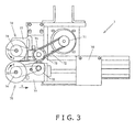
- the brush unit 7 is a component for drawing in the sealed parts Z of the bags X and smoothing out wrinkles or creases in the sealed parts Z, as shown in FIG. 3 .
- the brush unit 7 has a drive pulley 71 driven by a motor, a driven pulley 73 to which the rotation of the drive pulley 71 is transmitted through a timing belt 72, an upper shaft pulley 74 to which the rotation of the driven pulley 73 is transmitted through a timing belt, an upper rotating shaft 75 that rotates integrally with the shaft pulley 74, and an upper brush 76 attached to the rotating shaft 75.
- the driven pulley 73, the upper shaft pulley 74, the upper rotating shaft 75, and the upper brush 76 are supported on an upper support member 77.
- a drive roller 78 that rotates integrally with the driven pulley 73 is supported on the upper support member 77.
- a driven roller 79, a lower shaft pulley 74, a rotating shaft 75, and a lower brush 76 are supported on a lower support member 77, which is linked to a piston rod of a retracting cylinder 70.
- the driven roller 79 is rotated by being in contact with the drive roller 78.
- the rotation of the driven roller 79 is transmitted to the lower shaft pulley 74 through a timing belt.
- the rotating shaft 75 rotates integrally with the shaft pulley 74.
- the lower brush 76 is attached to the rotating shaft 75.
- the brush unit 7 is configured such that the sealed parts Z of the bags X are drawn and scrubbed in by the upper and lower brushes 76, 76 rotating in the directions of the arrows d while the sealed parts Z are in contact with the brushes from above and below.
- the brushes 76 have a structure in which a plurality of relatively thin discoid separated brushes is aligned at predetermined intervals on the rotating shafts 75.
- the brushes 76 are preferably, e.g., sponge-like brushes, steel wool-like brushes in which wires are interwoven radially, or the like.
- a pair of left and right grasping units 8, 8 (only one is shown) are disposed on both sides of the brush unit 7 and farther forward in the conveying direction b than the terminal end of the drop conveyor 5 which swings in the direction of the arrow f around the starting end, as shown in FIG. 4 .
- the grasping units 8 grasp the sealed parts Z at fronts of the bags X relative to the conveying direction at the tops and bottoms from the front of the conveying direction b, by means of a pair top and bottom grip fingers 81, 81.
- the bags X are moved at a downward incline as shown by the arrow g from the drawn-in position P1 in the brush unit 7 to the attaching position P2 in the attachment unit 9.
- the grip fingers 81, 81 are mounted on a hand 82.
- the hand 82 is attached to an arm 83 so that the longitudinal position of the hand can be adjusted.
- the arm 83 is provided to a guide rail 84 inclined so as to be capable of moving in the direction of the arrow g.
- the attachment unit 9 incorporated in the main unit 2 has a heater 91, a clamp 92, a pneumatic cylinder 93, a punch cutter unit 94, a melt prevention member 95, and a pneumatic cylinder 96, as shown in FIG. 5 .
- the heater 91 is a heat source for fusing together the tape T and the bags X.
- the clamp 92 together with the heater 91, clamps the tape T and the bags X.
- the pneumatic cylinder 93 raises and lowers the clamp 92.
- the punch cutter unit 94 forms a suitable punch hole T1 or perforation in the tape T.
- the melt prevention member 95 moves upward, thereby raising the tape T off of the heater 91 and preventing the tape T from melting.
- the pneumatic cylinder 96 raises and lowers the melt prevention member 95.
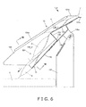
- the downward-inclined cradle 13 then discharges the strip pack SP in the direction of the arrow i and relays the strip pack SP to the discharge conveyor 6, the strip pack SP being made of bags X moved by the grasping units 8 in the direction of the arrow g and attached to the tape T, as shown in FIGS. 6 through 8 .
- the cradle 13 is a thin metal plate that has been formed into a substantial chute shape by bending or the like.
- the cradle 13 has a first receiving surface 131 and a second receiving surface 132.
- the first receiving surface 131 is provided on the upstream side, and the first receiving surface 131 receives a bag X attached to the tape T.
- the second receiving surface 132 is provided downstream of the first receiving surface 131, and the second receiving surface 132 receives the bags X, X that have been attached to the tape T ahead of the first bag X.
- the second receiving surface 132 is designed to have a slightly steeper incline than the first receiving surface 131.
- the second receiving surface 132 is also farther down than the first receiving surface 131 due to a stepped part 133.
- An induction piece 131a for allowing the bags X attached to the tape T to be easily guided in extends substantially horizontally from the front edge of the downward-inclined first receiving surface 131.
- Side surfaces 134, 134 stand upright respectively from the left and right ends of the receiving surfaces 131, 132.
- the side surfaces 134 have induction pieces 134a, 134b provided so as to bend outward at an incline from the top edges of the vertical portions of the side surfaces.
- the role of the induction pieces 134a, 134b is to allow the bags X to be easily guided in from above.
- the side surfaces 134, 134 can be treated separately as first side surfaces 134-1, 134-1 corresponding to the first receiving surface 131, and second side surfaces 134-2, 134-2 corresponding to the second receiving surface 132.
- the guide surfaces 135, 135 are inclined in relation to the horizontal surfaces and vertical surfaces, and are formed so as to widen as they progress downstream.
- the second receiving surface 132 accordingly narrows as it progresses downstream. Therefore, the surface area of contact between the guide surfaces 135, 135 and the bags X, X first attached to the tape T increases as the bags X, X move downstream in synchronization with the tape T feed, and the result is that the bags X, X are brought progressively nearer to the middle of the second receiving surface 132.
- the second receiving surface 132, the side surfaces 134-2, 134-2, and the guide surfaces 135, 135 constitute a drop-in part D into which drop the bags X, X that have attached to the tape T ahead of the other attached bag X.
- An attachment member 136 is fixed in place spanning the reverse sides of the receiving surfaces 131, 132.
- the cradle 13 is supported via connecting pieces 136a, 136a extending from the left and right side edges of the attachment member 136 on a support stand 137 provided to the main unit 2.
- the bags X moved to the attaching position P2 by the grasping units 8 and attached to the tape T are mostly supported by the first receiving surface 131, as shown in FIG. 6 .
- the latter bag X of the bags X, X attached to the tape T ahead of the other bag X ceases to be supported by the first receiving surface 131, and this latter bag X slides down and drops into the drop-in part D.
- the former bag X ceases to be supported by the second receiving surface 132 and slides down so as to fall onto the discharge conveyor 6.
- the cradle 13 for controlling the orientation of the bags X, X attached to the tape T ahead of the other attached bag X is provided downstream of the attachment unit 9, the orientation of the tape T is stabilized upstream, and the positional relationship between the tape T and the bags X next to be attached is stabilized. Consequently, the bags X can be sequentially attached to the tape T with a stabilized orientation. Downstream, the attached bags X, X can be discharged with their orientations kept in order.
- the cradle 13 has a first receiving surface 131 for receiving the bags X consecutively arranged and attached in the attachment unit 9. Therefore, in addition to controlling the longitudinal orientation of the bags X, it is also possible to forestall sagging of the bags X, which can occur in cases in which the sealed parts Z of the bags X are attached to the tape T by the attachment unit 9 from a substantially vertical direction; i.e., it is possible to forestall damage due to wrinkles, pinholes, and other problems resulting from creasing of the sealed parts Z.
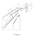
- a bag X 1 that follows the bags X 2 , X 3 previously attached to the tape T and that is grasped at the sealed part Z by the grip fingers 81, 81 of the grasping units 8 is moved to the attaching position P2 in the attachment unit 9 and attached to the tape T, as shown in FIG. 9 , for example.
- the bag X 1 is supported by the first receiving surface 131 and/or induction piece 131a of the cradle 13, and creasing of the sealed part Z grasped by the grip fingers 81, 81 is therefore suppressed.
- the cradle 13 Downstream of the first receiving surface 131, the cradle 13 has a drop-in part D for receiving dropped-in bags X, X attached to the tape T ahead of the other attached bag X. It is therefore possible to effectively prevent the past problem in which bag X is lifted too high, causing an attachment defect.
- the configuration includes bags X 1 ' to X 4 ', having larger bulges than the bags X, attached to the tape T.
- the bag X 1 ' moved by the grasping units 8 to the attaching position P2 in the attachment unit 9 is being attached to the tape T and is supported on the induction piece 131a and/or the starting end of the first receiving surface 131 of the cradle 13.
- the bag X 2 ' attached earlier to the tape T is supported in the vicinity of the terminal end of the first receiving surface 131, the bag X 3 ' drops into the drop-in part D, and the bag X 4 ' is supported in the vicinity of the terminal end of the second receiving surface 132.
- providing a drop-in part D prevents the bag X 1 ' from being lifted up by the first attached bags X 2 ' to X 4 ', even with bags X 1 ' to X 4 ' that would be significantly lifted up due to their large bulges. Therefore, the bag X 1 ' is positioned appropriately in relation to the attachment unit 9 without interference.
- the drop-in part D has a second receiving surface 132, second side surfaces 134-2, 134-2, and guide surfaces 135, 135, the bags X, X attached to the tape T ahead of the other attached bag X and supported on the second receiving surface 132 are effectively centered.
- the guide surfaces 135, 135 in particular are formed as inclined surfaces or curved surfaces, whereby the bags X can be centered while flexibly corresponding to the widths of the bags X.
- the cradle 13' of the modification is configured so that the terminal end is capable of swinging in the direction of the arrow j around the starting end supported on the top end of the support stand 137, as shown in FIG. 11 .
- a first connecting piece 136a of the attachment member 136 of the cradle 13' is swingably connected to the top end of the support stand 137.
- a second connecting piece 136b is provided extending from the second receiving surface 132 of the attachment member 136, and the distal end of a piston rod of a pneumatic cylinder 138 whose proximal end is supported on the support stand 137 is connected to the second connecting piece 136b.
- the rod is made to advance by the action of the pneumatic cylinder 138, and the first receiving surface 131 is made to be substantially horizontal. Consequently, in this case, the bag X 1 moved by the grasping units 8 and attached to the tape T is supported substantially horizontally by the first receiving surface 131, and excessive creasing in the sealed part Z of the bag X 1 is therefore suppressed. As a result, the previously described occurrence of wrinkles or pinholes in the sealed part Z is further prevented.
- the rod is retracted by the action of the pneumatic cylinder 138, and the cradle 13' is swung in the direction of the arrow j around the first connecting piece 136a so that the first receiving surface 131 becomes inclined. Consequently, in this case, the bag X 1 attached to the tape T slides smoothly down the first receiving surface 131 towards the second receiving surface 132, then slides down the second receiving surface 132 together with the bags X 2 and X 3 attached earlier to the tape T to be received on the discharge conveyor 6.
- the guide surfaces 135 provided in the drop-in part D were configured as inclined surfaces, but they may also be curved surfaces. If there is no fluctuation in the widths of the supplied bags X, the guide surfaces 135 are not needed.
- the drop-in part D had a second receiving surface 132, but if the bags X, X attached to the tape T ahead of the other attached bag X do not twist, or if the bags are lightweight, the second receiving surface 132 may be omitted, leaving only the side surfaces 134, 134 and the guide surfaces 135, 135.
- the second receiving surface may also be inclined toward one side. According to this configuration, the bags X can be moved toward this side surface via the widthwise incline, and the orientations of the bags X can be controlled by this side surface. Therefore, a receiving surface is obtained whereby the orientations of the bags X can be reliably controlled while flexibly corresponding to the widths of the bags X.
- a strip-pack manufacturing apparatus whereby articles can be sequentially attached with a stabilized orientation to a strip, and the attached articles can be discharged with their orientations kept in order. Furthermore, the articles can be prevented from faulty attachment to the strip.
- the present invention is widely suitable to the technological field of article packaging machinery.
Landscapes
- Engineering & Computer Science (AREA)
- Mechanical Engineering (AREA)
- Auxiliary Devices For And Details Of Packaging Control (AREA)
Abstract
The present invention provides a strip-pack manufacturing apparatus whereby articles can be sequentially attached with a stabilized orientation to a strip, and the attached articles can be discharged with their orientations kept in order. In this apparatus, a cradle (13) disposed downstream of an attachment unit is provided for controlling the orientations of bags (X, X) attached to a tape (T) ahead of another attached bag (X). A downstream drop-in part (D), into which articles drop from an upstream first receiving surface (131) of the cradle (13), is configured from a second receiving surface (132), left and right second side surfaces (134) thereof, and left and right guide surfaces (135).
Description
- The present invention relates to a strip-pack manufacturing apparatus for manufacturing a product known as a strip pack wherein a plurality of articles are attached to a strip and displayed while hanging, and the present invention pertains to the technological field of article packaging machinery.
- There are products known as strip packs, wherein a plurality of articles filled with snack food or the like are aligned on and attached to a strip, from which the articles are hung on display. The advantage of a strip pack is that less space is needed for the display, the displays in aisles or other areas of a store, for example, are more likely to be noticed by consumers, which promotes sales.
- An example of a strip-pack manufacturing apparatus for manufacturing such strip packs is the apparatus disclosed in Japanese Laid-open Patent Application No.
2007-112502 - The apparatus disclosed in Japanese Patent No.
3602527 - The following such problems are sometimes encountered with the strip-pack manufacturing apparatuses disclosed in the aforementioned publications. Specifically, as articles are sequentially attached to the strip, the articles that have been attached to the strip ahead of the other attached articles unexpectedly twist or move to the left and right and their orientations fluctuate, as can be easily seen by referring to
FIG. 2 of Japanese Laid-open Patent Application No.2007-112502 FIG. 4 of Japanese Patent No.3602527 - Furthermore, as the articles are sequentially attached to the strip, the articles being attached later to the strip are sequentially lifted up by the articles being attached earlier to the strip because of the relationship between the degree of incline of the cradle and the bulging of the articles, as can be easily seen by referring to
FIG. 2 of Japanese Laid-open Patent Application No.2007-112502 - In view of this fact, an object of the present invention is to provide a strip-pack manufacturing apparatus whereby articles can be sequentially attached with a stabilized orientation to a strip, and the attached articles can be discharged with their orientations in order. Another object of the present invention is to suppress attachment errors of the articles onto the strip.
- A strip-pack manufacturing apparatus according to the present invention comprises attachment means for attaching the ends of articles to a strip, and orientation control means. The orientation control means is disposed downstream of the attachment means, and the orientation control means controls the orientation of another article attached to the strip ahead of one attached article.
- The orientation control means preferably has side surfaces for controlling the lateral orientation of the other article.
- Alternatively, the orientation control means preferably has a first receiving surface for receiving the one article, the first receiving surface being disposed so as to be consecutive the attachment means. In this case, it is preferred that first side surfaces for controlling the lateral orientation of the one article also be provided adjacent to the first receiving surface. The orientation control means also preferably has a drop-in part into which the other article drops downstream of the first receiving surface. In cases in which the drop-in part is provided, the drop-in part preferably has a second receiving surface. Furthermore, the drop-in part also preferably has second side surfaces disposed on the sides of the second receiving surface, and guide surfaces disposed between the second receiving surface and the second side surfaces to guide the other article to the center of the second receiving surface.
- According to the present invention, orientation control means is provided downstream of the attachment means for controlling the orientation of another article (second article) attached to a strip ahead of one attached article (first article); therefore, the orientation of the strip upstream is stabilized, and the positional relationship between the strip and new articles coming to be attached is stabilized. Consequently, articles can be sequentially attached with a stabilized orientation to the strip. The attached articles can be discharged on the downstream side with their orientations in order.
- In cases in which the orientation control means has side surfaces for controlling the lateral orientations of the articles, lateral movement of the articles, which is particularly likely, is controlled. As a result, lateral movement of the strip on the upstream side is controlled, and the lateral orientations of the attached articles on the downstream side are kept in order.
- In cases in which the orientation control means has a first receiving surface, in addition to the longitudinal orientations of the articles being controlled, it is possible to forestall articles from hanging down in cases in which the ends of the articles are attached to the strip substantially from a substantially vertical direction by the attachment means; i.e., to forestall wrinkles, pinholes, and other damages resulting from creasing in the ends. Furthermore, in cases in which the first receiving surface has first side surfaces, the lateral movement of the first article is controlled; therefore, lateral movement of the strip is controlled, further assisting the articles in being attached with stabilized orientations to the strip.
- In cases in which the orientation control means has a drop-in part, it is possible to effectively prevent the past problem of attachment errors resulting from too many articles being lifted up. Furthermore, in cases in which the drop-in part has a second receiving surface, the second article is supported on the second receiving surface. Consequently, the orientation of the strip on the upstream side is reliably controlled, and the orientations of the attached articles on the downstream side are reliably kept in order.
- The second article is effectively centered in cases in which the drop-in part has a second receiving surface, second side surfaces, and guide surfaces. In this case, in particular, forming the guide surfaces as inclined surfaces or curved surfaces makes it possible to center the articles while adapting to the width dimensions of the articles.
-
-
FIG. 1 is a side view of the strip-pack manufacturing apparatus according to an embodiment of the present invention. -
FIG. 2A is a plan view of a bag supplied to the strip-pack manufacturing apparatus. -
FIG. 2B is a plan view of a strip pack manufactured by the strip-pack manufacturing apparatus. -
FIG. 3 is a side view of the brush unit. -
FIG. 4 is a side view showing the grasping units and the positional relationship between the drawn-in position and the attaching position. -
FIG. 5 is a side view of the attachment unit. -
FIG. 6 is a cross-sectional side view of the cradle. -
FIG. 7 is a plan view of the cradle. -
FIG. 8 is a cross-sectional view along the line VIII-VIII inFIG. 6 . -
FIG. 9 is a partial cross-sectional view for describing the action of the first receiving surface. -
FIG. 10 is a partial cross-sectional view for describing the action of the drop-in part. -
FIG. 11 is a side view showing a modification of the cradle. -
- 1
- Strip-pack manufacturing apparatus
- 9
- Attachment unit (attachment means)
- 13, 13'
- Cradle (orientation control means)
- 131
- First receiving surface
- 132
- Second receiving surface
- 134
- Side surface
- 134-1
- First side surface
- 134-2
- Second side surface
- 135
- Guide surfaces
- D
- Drop-in part
- T
- Tape (strip)
- X, X1 - X3, X1' - X4'
- Bags (articles)
- Embodiments of the present invention are described hereinbelow.
- A strip-
pack manufacturing apparatus 1 according to an embodiment of the present invention is composed of amain unit 2, asupply conveyor 3, an induction conveyor 4, adrop conveyor 5, adischarge conveyor 6, abrush unit 7, a graspingunit 8, anattachment unit 9, atape feed unit 10, afalloff prevention member 12, acradle 13, and other components, as shown inFIG. 1 . - Bags X filled with handled articles (e.g., snack foods or the like) are supplied to the
supply conveyor 3 from a separate upstream device. - The induction conveyor 4 guides bags X supplied in the direction of the arrow a by the
supply conveyor 3 into themain device 1, as shown by the arrow b. Thedrop conveyor 5 constitutes the terminal end of the induction conveyor 4. - The
discharge conveyor 6 discharges a strip pack SP made of a plurality of bags X...X attached to tape to a downstream device as shown by the arrow c. - The
brush unit 7 is disposed farther forward in the conveying direction b than the terminal end of thedrop conveyor 5, and thebrush unit 7 draws in the ends of the bags X guided in by thedrop conveyor 5 and smoothes out wrinkles or creases in the ends. - The grasping
unit 8 is disposed farther forward in the conveying direction b than the terminal end of thedrop conveyor 5, and the graspingunit 8 grasps the ends of the bags X received from thedrop conveyor 5 and moves the ends from a drawn-in position P1 to an attaching position P2 below and farther forward in the conveying direction b than the terminal end of thedrop conveyor 5. - The
attachment unit 9 attaches the ends of the bags X to the tape, the bags X having been grasped and moved to the attaching position P2 by the graspingunit 8. - The
tape feed unit 10 feeds the tape synchronously with the manufacturing of the strip pack SP. Aroll 11 of the tape is set up at the top of themain unit 2. - The
falloff prevention member 12 is placed at the starting end of the induction conveyor 4, and thefalloff prevention member 12 prevents bags X falling from thesupply conveyor 3 from falling off of themain device 1. - The
cradle 13 is a table for relaying the manufactured strip pack SP from theattachment unit 9 to thedischarge conveyor 6, and is inclined downward. - The bags X supplied to the
main device 1 each have an empty part Y filled with snack food or the like, and sealed parts Z, Z as two ends, one upper and one lower, as shown inFIG. 2A . The strip pack SP manufactured by themain device 1 is made of a plurality of bags X... X attached to a long, thin tape T and aligned by their respective upper sealed parts Z...Z, as shown inFIG. 2B . A punch hole T1 for interlocking with the strip pack SP and displaying the strip pack SP in a hanging state is formed in one end of the tape T. - The
brush unit 7 is a component for drawing in the sealed parts Z of the bags X and smoothing out wrinkles or creases in the sealed parts Z, as shown inFIG. 3 . Thebrush unit 7 has adrive pulley 71 driven by a motor, a drivenpulley 73 to which the rotation of thedrive pulley 71 is transmitted through atiming belt 72, anupper shaft pulley 74 to which the rotation of the drivenpulley 73 is transmitted through a timing belt, an upperrotating shaft 75 that rotates integrally with theshaft pulley 74, and anupper brush 76 attached to therotating shaft 75. The drivenpulley 73, theupper shaft pulley 74, the upperrotating shaft 75, and theupper brush 76 are supported on anupper support member 77. - A
drive roller 78 that rotates integrally with the drivenpulley 73 is supported on theupper support member 77. A drivenroller 79, alower shaft pulley 74, a rotatingshaft 75, and alower brush 76 are supported on alower support member 77, which is linked to a piston rod of a retractingcylinder 70. The drivenroller 79 is rotated by being in contact with thedrive roller 78. The rotation of the drivenroller 79 is transmitted to thelower shaft pulley 74 through a timing belt. The rotatingshaft 75 rotates integrally with theshaft pulley 74. Thelower brush 76 is attached to therotating shaft 75. - In other words, the
brush unit 7 is configured such that the sealed parts Z of the bags X are drawn and scrubbed in by the upper andlower brushes - The
brushes 76 have a structure in which a plurality of relatively thin discoid separated brushes is aligned at predetermined intervals on therotating shafts 75. Thebrushes 76 are preferably, e.g., sponge-like brushes, steel wool-like brushes in which wires are interwoven radially, or the like. - When the
lower support member 77 of thebrush unit 7 retracts in the direction of the arrow e due to the action of the retractingcylinder 70, thelower brush 76 also retracts in the direction of the arrow e. The bags X whose sealed parts Z have been drawn in by the rotation of the upper andlower brushes brush unit 7 to the attaching position P2 in theattachment unit 9. - A pair of left and right grasping
units 8, 8 (only one is shown) are disposed on both sides of thebrush unit 7 and farther forward in the conveying direction b than the terminal end of thedrop conveyor 5 which swings in the direction of the arrow f around the starting end, as shown inFIG. 4 . The graspingunits 8 grasp the sealed parts Z at fronts of the bags X relative to the conveying direction at the tops and bottoms from the front of the conveying direction b, by means of a pair top andbottom grip fingers brush unit 7 to the attaching position P2 in theattachment unit 9. Thegrip fingers hand 82. Thehand 82 is attached to anarm 83 so that the longitudinal position of the hand can be adjusted. Thearm 83 is provided to aguide rail 84 inclined so as to be capable of moving in the direction of the arrow g. - The
attachment unit 9 incorporated in themain unit 2 has aheater 91, aclamp 92, apneumatic cylinder 93, apunch cutter unit 94, amelt prevention member 95, and apneumatic cylinder 96, as shown inFIG. 5 . Theheater 91 is a heat source for fusing together the tape T and the bags X. Theclamp 92, together with theheater 91, clamps the tape T and the bags X. Thepneumatic cylinder 93 raises and lowers theclamp 92. Thepunch cutter unit 94 forms a suitable punch hole T1 or perforation in the tape T. Themelt prevention member 95 moves upward, thereby raising the tape T off of theheater 91 and preventing the tape T from melting. Thepneumatic cylinder 96 raises and lowers themelt prevention member 95. - The downward-
inclined cradle 13 then discharges the strip pack SP in the direction of the arrow i and relays the strip pack SP to thedischarge conveyor 6, the strip pack SP being made of bags X moved by the graspingunits 8 in the direction of the arrow g and attached to the tape T, as shown inFIGS. 6 through 8 . - The
cradle 13 is a thin metal plate that has been formed into a substantial chute shape by bending or the like. Thecradle 13 has afirst receiving surface 131 and asecond receiving surface 132. Thefirst receiving surface 131 is provided on the upstream side, and thefirst receiving surface 131 receives a bag X attached to the tape T. Thesecond receiving surface 132 is provided downstream of thefirst receiving surface 131, and thesecond receiving surface 132 receives the bags X, X that have been attached to the tape T ahead of the first bag X. Thesecond receiving surface 132 is designed to have a slightly steeper incline than thefirst receiving surface 131. Thesecond receiving surface 132 is also farther down than thefirst receiving surface 131 due to a steppedpart 133. Increasing the incline of thesecond receiving surface 132 in this manner allows the bags X, X first attached to the tape T to slide smoothly down and be received on thedischarge conveyor 6. Aninduction piece 131a for allowing the bags X attached to the tape T to be easily guided in extends substantially horizontally from the front edge of the downward-inclined first receivingsurface 131. - Side surfaces 134, 134 stand upright respectively from the left and right ends of the receiving
surfaces induction pieces induction pieces first receiving surface 131, and second side surfaces 134-2, 134-2 corresponding to thesecond receiving surface 132. Provided along the vertical surfaces between thesecond receiving surface 132 and the side surfaces 134-2, 134-2 areguide surfaces second receiving surface 132. The guide surfaces 135, 135 are inclined in relation to the horizontal surfaces and vertical surfaces, and are formed so as to widen as they progress downstream. Thesecond receiving surface 132 accordingly narrows as it progresses downstream. Therefore, the surface area of contact between the guide surfaces 135, 135 and the bags X, X first attached to the tape T increases as the bags X, X move downstream in synchronization with the tape T feed, and the result is that the bags X, X are brought progressively nearer to the middle of thesecond receiving surface 132. Thesecond receiving surface 132, the side surfaces 134-2, 134-2, and the guide surfaces 135, 135 constitute a drop-in part D into which drop the bags X, X that have attached to the tape T ahead of the other attached bag X. - An
attachment member 136 is fixed in place spanning the reverse sides of the receivingsurfaces cradle 13 is supported via connectingpieces attachment member 136 on asupport stand 137 provided to themain unit 2. - The bags X moved to the attaching position P2 by the grasping
units 8 and attached to the tape T are mostly supported by thefirst receiving surface 131, as shown inFIG. 6 . The latter bag X of the bags X, X attached to the tape T ahead of the other bag X ceases to be supported by thefirst receiving surface 131, and this latter bag X slides down and drops into the drop-in part D. InFIG. 6 , the former bag X ceases to be supported by thesecond receiving surface 132 and slides down so as to fall onto thedischarge conveyor 6. - (1) Since the
cradle 13 for controlling the orientation of the bags X, X attached to the tape T ahead of the other attached bag X is provided downstream of theattachment unit 9, the orientation of the tape T is stabilized upstream, and the positional relationship between the tape T and the bags X next to be attached is stabilized. Consequently, the bags X can be sequentially attached to the tape T with a stabilized orientation. Downstream, the attached bags X, X can be discharged with their orientations kept in order. - (2) Next, since the
cradle 13 has side surfaces 134, 134 for controlling the transverse orientation of the bags X, X attached to the tape T ahead of the other attached bag X, transverse movement of the bags X, which is particularly likely to occur, is controlled. As a result, transverse movement of the tape T is controlled upstream, and the transverse orientations of the attached bags X, X are kept in order downstream. - (3) The
cradle 13 has afirst receiving surface 131 for receiving the bags X consecutively arranged and attached in theattachment unit 9. Therefore, in addition to controlling the longitudinal orientation of the bags X, it is also possible to forestall sagging of the bags X, which can occur in cases in which the sealed parts Z of the bags X are attached to the tape T by theattachment unit 9 from a substantially vertical direction; i.e., it is possible to forestall damage due to wrinkles, pinholes, and other problems resulting from creasing of the sealed parts Z. - A bag X1 that follows the bags X2, X3 previously attached to the tape T and that is grasped at the sealed part Z by the
grip fingers units 8 is moved to the attaching position P2 in theattachment unit 9 and attached to the tape T, as shown inFIG. 9 , for example. In this case, the bag X1 is supported by thefirst receiving surface 131 and/orinduction piece 131a of thecradle 13, and creasing of the sealed part Z grasped by thegrip fingers - (4) Since the first side surfaces 134-1, 134-1 stand upright from both ends of the
first receiving surface 131, the transverse movement of the bag X attached to the tape T after the first attached bags X, X is controlled. Consequently, the transverse movement of the tape T is controlled, further assisting the bags X in being attached to the tape T with a stabilized orientation. - (5) Downstream of the
first receiving surface 131, thecradle 13 has a drop-in part D for receiving dropped-in bags X, X attached to the tape T ahead of the other attached bag X. It is therefore possible to effectively prevent the past problem in which bag X is lifted too high, causing an attachment defect. - In this case, as shown in
FIG. 10 for example, the configuration includes bags X1' to X4', having larger bulges than the bags X, attached to the tape T. In this illustrated example, the bag X1' moved by the graspingunits 8 to the attaching position P2 in theattachment unit 9 is being attached to the tape T and is supported on theinduction piece 131a and/or the starting end of thefirst receiving surface 131 of thecradle 13. The bag X2' attached earlier to the tape T is supported in the vicinity of the terminal end of thefirst receiving surface 131, the bag X3' drops into the drop-in part D, and the bag X4' is supported in the vicinity of the terminal end of thesecond receiving surface 132. - Thus, providing a drop-in part D prevents the bag X1' from being lifted up by the first attached bags X2' to X4', even with bags X1' to X4' that would be significantly lifted up due to their large bulges. Therefore, the bag X1' is positioned appropriately in relation to the
attachment unit 9 without interference. - (6) Since the drop-in part D has a
second receiving surface 132, the bags X, X attached to the tape T ahead of the other attached bag X are supported on thesecond receiving surface 132. Therefore, the orientation of the tape T is reliably controlled upstream, and the orientations of the attached bags X, X are reliably kept in order downstream. - Since the drop-in part D has a
second receiving surface 132, second side surfaces 134-2, 134-2, and guidesurfaces second receiving surface 132 are effectively centered. In this case, the guide surfaces 135, 135 in particular are formed as inclined surfaces or curved surfaces, whereby the bags X can be centered while flexibly corresponding to the widths of the bags X. - Next, a modification of the cradle will be described. The same numerical symbols are used for structural elements common to the previously described embodiment.
- The cradle 13' of the modification is configured so that the terminal end is capable of swinging in the direction of the arrow j around the starting end supported on the top end of the
support stand 137, as shown inFIG. 11 . A first connectingpiece 136a of theattachment member 136 of the cradle 13' is swingably connected to the top end of thesupport stand 137. A second connecting piece 136b is provided extending from thesecond receiving surface 132 of theattachment member 136, and the distal end of a piston rod of apneumatic cylinder 138 whose proximal end is supported on thesupport stand 137 is connected to the second connecting piece 136b. - According to this configuration, the rod is made to advance by the action of the
pneumatic cylinder 138, and thefirst receiving surface 131 is made to be substantially horizontal. Consequently, in this case, the bag X1 moved by the graspingunits 8 and attached to the tape T is supported substantially horizontally by thefirst receiving surface 131, and excessive creasing in the sealed part Z of the bag X1 is therefore suppressed. As a result, the previously described occurrence of wrinkles or pinholes in the sealed part Z is further prevented. - Next, as shown by the faint double-dashed lines, the rod is retracted by the action of the
pneumatic cylinder 138, and the cradle 13' is swung in the direction of the arrow j around the first connectingpiece 136a so that thefirst receiving surface 131 becomes inclined. Consequently, in this case, the bag X1 attached to the tape T slides smoothly down thefirst receiving surface 131 towards thesecond receiving surface 132, then slides down thesecond receiving surface 132 together with the bags X2 and X3 attached earlier to the tape T to be received on thedischarge conveyor 6. - The present invention is not limited to the specifically described embodiment, and any modification that conforms to the essence of the present invention is acceptable.
- For example, in the embodiment, the guide surfaces 135 provided in the drop-in part D were configured as inclined surfaces, but they may also be curved surfaces. If there is no fluctuation in the widths of the supplied bags X, the guide surfaces 135 are not needed.
- In the previously described embodiments, the drop-in part D had a
second receiving surface 132, but if the bags X, X attached to the tape T ahead of the other attached bag X do not twist, or if the bags are lightweight, thesecond receiving surface 132 may be omitted, leaving only the side surfaces 134, 134 and the guide surfaces 135, 135. - The second receiving surface may also be inclined toward one side. According to this configuration, the bags X can be moved toward this side surface via the widthwise incline, and the orientations of the bags X can be controlled by this side surface. Therefore, a receiving surface is obtained whereby the orientations of the bags X can be reliably controlled while flexibly corresponding to the widths of the bags X.
- According to the present invention as described above, a strip-pack manufacturing apparatus is provided, whereby articles can be sequentially attached with a stabilized orientation to a strip, and the attached articles can be discharged with their orientations kept in order. Furthermore, the articles can be prevented from faulty attachment to the strip. Specifically, the present invention is widely suitable to the technological field of article packaging machinery.
Claims (7)
- A strip-pack manufacturing apparatus comprising:attachment means for attaching the ends of articles to a strip; andorientation control means disposed downstream of the attachment means for controlling the orientation of another article attached to the strip ahead of one attached article.
- The strip-pack manufacturing apparatus according to claim 1, wherein
the orientation control means has side surfaces for controlling the lateral orientation of the other article. - The strip-pack manufacturing apparatus according to claim 1, wherein
the orientation control means has a first receiving surface for receiving the one article, the first receiving surface being disposed so as to be consecutive to the attachment means. - The strip-pack manufacturing apparatus according to claim 3, wherein
the orientation control means further has a first side surface adjacent to the first receiving surface for controlling the lateral orientation of the one article. - The strip-pack manufacturing apparatus according to claim 3 or 4, wherein
the orientation control means further has a drop-in part into which the other article drops downstream of the first receiving surface. - The strip-pack manufacturing apparatus according to claim 5, wherein
the drop-in part has a second receiving surface. - The strip-pack manufacturing apparatus according to claim 6, wherein
the drop-in part further has second side surfaces disposed on both sides of the second receiving surface, and guide surfaces disposed between the second receiving surface and the second side surfaces for guiding the other article to the center of the second receiving surface.
Applications Claiming Priority (2)
| Application Number | Priority Date | Filing Date | Title |
|---|---|---|---|
| JP2007268572A JP2009096497A (en) | 2007-10-16 | 2007-10-16 | Strip pack equipment |
| PCT/JP2008/067801 WO2009051007A1 (en) | 2007-10-16 | 2008-10-01 | Strip pack device |
Publications (1)
| Publication Number | Publication Date |
|---|---|
| EP2213574A1 true EP2213574A1 (en) | 2010-08-04 |
Family
ID=40567280
Family Applications (1)
| Application Number | Title | Priority Date | Filing Date |
|---|---|---|---|
| EP08839014A Withdrawn EP2213574A1 (en) | 2007-10-16 | 2008-10-01 | Strip pack device |
Country Status (5)
| Country | Link |
|---|---|
| US (1) | US20100223885A1 (en) |
| EP (1) | EP2213574A1 (en) |
| JP (1) | JP2009096497A (en) |
| CN (1) | CN101827752B (en) |
| WO (1) | WO2009051007A1 (en) |
Family Cites Families (12)
| Publication number | Priority date | Publication date | Assignee | Title |
|---|---|---|---|---|
| US3864895A (en) * | 1973-02-26 | 1975-02-11 | Wright Machinery Company Inc | Multi-pack method and apparatus |
| JP2557818Y2 (en) * | 1992-04-28 | 1997-12-17 | 三菱瓦斯化学株式会社 | Apparatus for fixing small bags in hot melt adhesive |
| US5433060A (en) * | 1994-02-10 | 1995-07-18 | Recot, Inc. | Automated method and apparatus for detachably securing flexible packages to a display strip |
| JP4094166B2 (en) * | 1999-04-07 | 2008-06-04 | 株式会社イシダ | Packaging system |
| US6726794B2 (en) * | 2001-03-15 | 2004-04-27 | Rudolph Foods Company, Inc. | Apparatus and method for producing a merchandiser and a pre-loaded merchandiser produced thereby |
| JP4025151B2 (en) * | 2002-08-29 | 2007-12-19 | 株式会社イシダ | Bag making and packaging machine |
| US7093404B2 (en) * | 2002-08-29 | 2006-08-22 | Ishida Co., Ltd. | Bag manufacturing and packaging apparatus |
| US7293591B2 (en) * | 2003-02-28 | 2007-11-13 | Ishida Co., Ltd. | System for mounting products to a tape |
| JP4256181B2 (en) * | 2003-02-28 | 2009-04-22 | 株式会社イシダ | Product inspection apparatus, strip tape mounting system and boxing system provided with the same |
| JP3602527B1 (en) * | 2003-06-19 | 2004-12-15 | 株式会社イシダ | Strip bag equipment |
| JP4704183B2 (en) * | 2005-10-24 | 2011-06-15 | 株式会社イシダ | Strip bag equipment |
| JP4907223B2 (en) * | 2006-05-15 | 2012-03-28 | 株式会社イシダ | Strip pack equipment |
-
2007
- 2007-10-16 JP JP2007268572A patent/JP2009096497A/en not_active Ceased
-
2008
- 2008-10-01 CN CN200880111861XA patent/CN101827752B/en not_active Expired - Fee Related
- 2008-10-01 US US12/682,170 patent/US20100223885A1/en not_active Abandoned
- 2008-10-01 WO PCT/JP2008/067801 patent/WO2009051007A1/en not_active Ceased
- 2008-10-01 EP EP08839014A patent/EP2213574A1/en not_active Withdrawn
Non-Patent Citations (1)
| Title |
|---|
| See references of WO2009051007A1 * |
Also Published As
| Publication number | Publication date |
|---|---|
| CN101827752B (en) | 2012-06-06 |
| US20100223885A1 (en) | 2010-09-09 |
| CN101827752A (en) | 2010-09-08 |
| JP2009096497A (en) | 2009-05-07 |
| WO2009051007A1 (en) | 2009-04-23 |
Similar Documents
| Publication | Publication Date | Title |
|---|---|---|
| JP3974409B2 (en) | Conveying device and boxing device provided with the same | |
| US9856047B2 (en) | Carton decasing system | |
| CA2869017C (en) | Carton decasing system | |
| EP2678232B1 (en) | Carton decasing system | |
| EP2708482A2 (en) | Reciprocating placer system | |
| JP2500273B2 (en) | Equipment for producing cartons from flat tube blanks | |
| US20100229502A1 (en) | Strip pack device | |
| US20100223885A1 (en) | Strip- pack manufacturing apparatus | |
| CN210557657U (en) | Positioning mechanism is carried to material | |
| EP2088082B1 (en) | Strip-pack apparatus, and gripping device and unwrinkling device for use in the apparatus | |
| US8047249B2 (en) | Strip pack apparatus | |
| JPH05132013A (en) | Boxing equipment | |
| JP6300151B2 (en) | Boxing method and boxing device for flat article | |
| JP4058686B2 (en) | Method and apparatus for supplying partition in boxing machine | |
| EP1024098A1 (en) | A method for palletising books, magazines, sheets, packages and the like | |
| JP4994785B2 (en) | Strip pack equipment | |
| JP4994784B2 (en) | Strip pack equipment | |
| US20040007805A1 (en) | Bag placer magazine | |
| JP4994783B2 (en) | Kneading and stretching device used in strip pack device and strip pack device using the same | |
| JPS6357288B2 (en) | ||
| JPH0977261A (en) | Molding stacking device | |
| JPH04267722A (en) | Direction feeding device for automatic packaging machine | |
| JPS62130972A (en) | Superposing method of soft article | |
| JPH0630005U (en) | Packaged product supply device | |
| JP2012001239A (en) | Band shrink wrapping apparatus |
Legal Events
| Date | Code | Title | Description |
|---|---|---|---|
| PUAI | Public reference made under article 153(3) epc to a published international application that has entered the european phase |
Free format text: ORIGINAL CODE: 0009012 |
|
| 17P | Request for examination filed |
Effective date: 20100517 |
|
| AK | Designated contracting states |
Kind code of ref document: A1 Designated state(s): AT BE BG CH CY CZ DE DK EE ES FI FR GB GR HR HU IE IS IT LI LT LU LV MC MT NL NO PL PT RO SE SI SK TR |
|
| AX | Request for extension of the european patent |
Extension state: AL BA MK RS |
|
| DAX | Request for extension of the european patent (deleted) | ||
| STAA | Information on the status of an ep patent application or granted ep patent |
Free format text: STATUS: THE APPLICATION HAS BEEN WITHDRAWN |
|
| 18W | Application withdrawn |
Effective date: 20131213 |
|
| RIC1 | Information provided on ipc code assigned before grant |
Ipc: B65B 15/04 20060101AFI20140129BHEP |