EP2213554A1 - Roll-over protection structure - Google Patents
Roll-over protection structure Download PDFInfo
- Publication number
- EP2213554A1 EP2213554A1 EP09178937A EP09178937A EP2213554A1 EP 2213554 A1 EP2213554 A1 EP 2213554A1 EP 09178937 A EP09178937 A EP 09178937A EP 09178937 A EP09178937 A EP 09178937A EP 2213554 A1 EP2213554 A1 EP 2213554A1
- Authority
- EP
- European Patent Office
- Prior art keywords
- rops
- plate
- base plate
- top plate
- bushing
- Prior art date
- Legal status (The legal status is an assumption and is not a legal conclusion. Google has not performed a legal analysis and makes no representation as to the accuracy of the status listed.)
- Withdrawn
Links
- 230000000712 assembly Effects 0.000 claims abstract description 4
- 238000000429 assembly Methods 0.000 claims abstract description 4
- 230000008878 coupling Effects 0.000 claims 1
- 238000010168 coupling process Methods 0.000 claims 1
- 238000005859 coupling reaction Methods 0.000 claims 1
- 238000005266 casting Methods 0.000 description 2
- 238000012986 modification Methods 0.000 description 2
- 230000004048 modification Effects 0.000 description 2
- 125000006850 spacer group Chemical group 0.000 description 2
- 229910000831 Steel Inorganic materials 0.000 description 1
- 238000002955 isolation Methods 0.000 description 1
- 239000010959 steel Substances 0.000 description 1
Images





Classifications
-
- B—PERFORMING OPERATIONS; TRANSPORTING
- B60—VEHICLES IN GENERAL
- B60R—VEHICLES, VEHICLE FITTINGS, OR VEHICLE PARTS, NOT OTHERWISE PROVIDED FOR
- B60R21/00—Arrangements or fittings on vehicles for protecting or preventing injuries to occupants or pedestrians in case of accidents or other traffic risks
- B60R21/02—Occupant safety arrangements or fittings, e.g. crash pads
- B60R21/13—Roll-over protection
- B60R21/131—Protective devices for drivers in case of overturning of tractors
Definitions
- the present invention relates to a Roll-over protection structure (ROPS), comprising a pair of legs and a pair of mounting assemblies for mounting the ROPS to a part of a vehicle, the mounting assembly comprising a base plate fixed to an end of a corresponding leg.
- ROPS Roll-over protection structure
- ROPS roll-over protection structure
- a ROPS structure must handle rear, side, & front roll-over loads.
- Most ROPS structures have included upright supports which require rigidity-adding longitudinal and lateral cross members topped by a canopy. Such structures are shown in the U.S. Pat. No. 3,787,085 granted to D. H. Bucher, et al on Jan. 22 1974 , and the U.S. Pat. No. 3,841,430 granted to J. H. Babbitt, Jr., et al on Oct. 15, 1974 .
- ROPS used on small agricultural tractors
- the lower ends of the U are attached to the frame of the tractor.
- vibrations in the frame are transmitted into the ROPS and the base of the U is positioned in the vicinity of the operator station of the vehicle.
- Other ROPS designs require a platform structure running forward to front mounts to help handle the loads, similar to a cab frame. Such a typical ROPS is not isolated from vibrations. Noise and vibration in the ROPS can be transmitted to a nearby vehicle operator.
- the problem to be solved is to provide a compact, cost effective ROPS mounting assembly which isolates the ROPS unit from vibration and noise.
- a roll-over protection system of the above mentioned type includes two legs or struts and a crossbar.
- Each mounting assembly includes a base plate fixed to an end of a corresponding leg, a support plate, a top plate and a resilient bushing unit separating the base plate from the support plate and from the top plate.
- the base plate is sandwiched between the support plate and the top plate.
- the bushing unit includes a first resilient bushing member separating the base plate from the support plate, and a second resilient bushing member separating the base plate from the top plate.
- the bushing unit also includes a rigid hollow sleeve which is received by the first and second resilient bushing members.
- One of the bushing members comprises a larger diameter cylindrical base and a small diameter cylindrical shaft. The shaft is received by a bore in the base plate.
- the other bushing members is an annular member which is partially received by a recess in the base plate.
- the base plate includes a bushing bore extending therethrough, and an annular bushing recess surrounds one end of the bushing bore.
- the support plate includes hollow mounting towers which project into bores in the base plate. Cap screws extend through the mounting assembly and attach it to a part of the vehicle, such as an axle housing. One of the cap screws extends through the bushing unit.
- an inverted U-shaped ROPS unit 10 has a pair of legs 12 and 14 which are mounted on a vehicle axle housing 16.
- ROPS unit 10 includes an inverted U-shaped upper part 18 which is pivotally coupled to legs 12 and 14. Upper part 18 may be pivotally lowered during low clearance transport conditions.
- a cross piece or brace 20 extends between and connects legs 12 and 14.
- An assembly 30 is also mounted on the axle housing 16. Assembly 30 includes a seat and floor platform 32 and a pair of fenders 34 and 36. The legs 12 and 14 are preferably attached to the corresponding adjacent fenders 34 and 36.
- the ROPS unit 10 includes a pair of mounting assemblies 44, 45 comprising a pair of base plates 40 and 42 which are welded to the bottom ends of legs 12 and 14, respectively. Each of plates 40 and 42 are coupled to the axle housing 16 by the corresponding and complimentary vibration isolating mounting assembly 44, 45.
- Mounting assembly 44 will be described in detail hereinafter, with the understanding that mounting assembly 45 is similar and may be a mirror image of mounting assembly 44.
- Mounting assembly 44 includes a support 46 which is preferably a cast part.
- Support 46 includes a support plate 48 from which project hollow internally threaded fingers or towers 50.
- a recess 52 is formed in the support plate 48, and a bore 54 extends through the support plate 48 at or near the center of the recess 52.
- Mounting assembly 44 also includes a bushing unit comprising a lower resilient bushing or isolator 56, an upper resilient bushing or isolator 58 and a hollow rigid, preferably steel, sleeve 60.
- Bushing 56 is received by recess 52 between the support 46 and the plate 42.
- Plate 42 includes a pair of drain holes 62 for cap screws which attach the plate 42 to the leg 14.
- Plate 42 also includes bores 64 which receive the fingers 50 and a bore 66 which receives the bushing 56 and the sleeve 60.
- a shallow annular recess 68 surrounds bore 66 and receives the lower end of bushing 58. Bore 66 receives a reduced diameter portion 57 of lower bushing 56.
- Mounting assembly 44 also includes a top plate 70 which mounted over the upper bushing 58 and the plate 42.
- Top plate 70 includes lower part 71 and a upper part 73.
- Lower part 71 engages the upper ends of two of the towers 50.
- Upper part 73 engages an upper end of the bushing 58.
- Top plate 70 also includes a spacer tab 75 which projects from the upper part 73.
- Top plate 70 includes bolt holes 72 which receive threaded members or cap screws 74 and 76. Cap screws 74 and 76 extend through the mounting assembly 44 and are threaded into threaded bores 80 in the upper surface of the axle housing 16 (two of which are visible in Fig. 7 ). Cap screws 74 extend through bolt holes 72, bores 64 and the towers 50.
- the other cap screw 76 extends through one of bolt holes 72, sleeve 60 of the bushing unit, bore 66 and bore 54.
- the towers 50 extend into the bores 64 in the base plate 42 and the bushing unit is received in bore 60 of the base plate 42.
- the lower part 71 of the top plate 70 engages only an upper end of the rear two towers 50 of the support plate 48 and is spaced apart from the base plate 42.
- the upper part 73 of the top plate 70 engages only the upper isolator 58 and the upper end of the sleeve 60, and is spaced apart from the base plate 42.
- the lower end of tab 75 is also spaced apart from the base plate 42.
- the four cap screws 74, 76 and the washers engage the top of the top plate 70.
- the support plate 48 engages and rests on the axle housing 16 and supports the top plate 70 and bottom isolator 56.
- the base plate 42 (in a nominal, non-roll condition) only engages the top isolator 58 and the bottom isolator 56 as it free floats between and spaced apart from the support plate 48 and the top plate 70.
- the ROPS unit 10 is resiliently coupled to the axle housing 16 and is isolated from the axle housing 16 with respect to vibration and noise.
- This mounting assembly is compact, cost effective and meets the necessary roll-over requirements and safety standards (loads & zone of clearance).
- the base plate 42 does not contact either the bottom casting 46 or the top plate 70. A nominal gap is maintained on both sides of the plate 42 which allows them to move up and down for isolation purposes.
- the bottom casting or support 46 mates to the rear axle housing 16 and acts as a spacer.
- the support 46 provides the mounting points (three towers 50) for the top plate 70, a mounting pad for the isolator bushing 56, and absorbs the reaction loads during a roll-over condition.
- the top plate 70 is bolted to the towers 50 of the support 46.
- the top plate 70 engages the top portion of the upper isolator or bushing 58.
- the cap screws 74, 76 engage the upper surface of the top plate 70, which supports the reaction loads during a roll-over condition.
- Each mounting assembly includes four cap screws 74, 76 to secure and retain each side of the ROPS unit 10.
Landscapes
- Engineering & Computer Science (AREA)
- Mechanical Engineering (AREA)
- Body Structure For Vehicles (AREA)
Abstract
A roll-over protection structure (10) (ROPS) is provided for a vehicle. The ROPS (10) includes a pair of legs (12, 14) and a pair of mounting assemblies (44, 45). Each mounting assembly (44, 45) includes a base plate (40, 42) fixed to an end of a corresponding leg (12, 14), a support plate (48), a top plate (70) and a resilient bushing unit which separates the base plate (40, 42) from the support and top plates (48, 70). The base plate (40, 42) is sandwiched between the support plate (48) and the top plate (70). The bushing unit includes first and second resilient bushing members (56, 58) and a rigid hollow central sleeve (60). The bushing unit is received by a bore (66) in the base plate (40, 42). The support plate (48) includes hollow mounting towers (50) which project into bores (64) in the base plate (40, 42). Cap screws (74, 76) attach the mounting assembly (44, 45) to a part of a vehicle. The top plate (70) and the support plate (48) are fixed to each other and to a part of a vehicle.
Description
- The present invention relates to a Roll-over protection structure (ROPS), comprising a pair of legs and a pair of mounting assemblies for mounting the ROPS to a part of a vehicle, the mounting assembly comprising a base plate fixed to an end of a corresponding leg.
- Many vehicles, including agricultural tractors, are provided with some form of roll-over protection structure or system, or ROPS. ROPS are designed to prevent the vehicle from crushing the operator if it accidentally rolls over. A ROPS structure must handle rear, side, & front roll-over loads. Most ROPS structures have included upright supports which require rigidity-adding longitudinal and lateral cross members topped by a canopy. Such structures are shown in the
U.S. Pat. No. 3,787,085 granted to D. H. Bucher, et al on Jan. 22 1974 , and theU.S. Pat. No. 3,841,430 granted to J. H. Babbitt, Jr., et al on Oct. 15, 1974 . - One common ROPS used on small agricultural tractors is a U-shaped bar. The lower ends of the U are attached to the frame of the tractor. As a result, vibrations in the frame are transmitted into the ROPS and the base of the U is positioned in the vicinity of the operator station of the vehicle. Other ROPS designs require a platform structure running forward to front mounts to help handle the loads, similar to a cab frame. Such a typical ROPS is not isolated from vibrations. Noise and vibration in the ROPS can be transmitted to a nearby vehicle operator.
- The problem to be solved then is to provide a compact, cost effective ROPS mounting assembly which isolates the ROPS unit from vibration and noise.
- The problem will be solved by the teaching of claim 1. Advantageous embodiments are defined within the subclaims.
- Accordingly a roll-over protection system (ROPS) of the above mentioned type includes two legs or struts and a crossbar. Each mounting assembly includes a base plate fixed to an end of a corresponding leg, a support plate, a top plate and a resilient bushing unit separating the base plate from the support plate and from the top plate.
- The base plate is sandwiched between the support plate and the top plate. The bushing unit includes a first resilient bushing member separating the base plate from the support plate, and a second resilient bushing member separating the base plate from the top plate. The bushing unit also includes a rigid hollow sleeve which is received by the first and second resilient bushing members. One of the bushing members comprises a larger diameter cylindrical base and a small diameter cylindrical shaft. The shaft is received by a bore in the base plate. The other bushing members is an annular member which is partially received by a recess in the base plate. The base plate includes a bushing bore extending therethrough, and an annular bushing recess surrounds one end of the bushing bore. The support plate includes hollow mounting towers which project into bores in the base plate. Cap screws extend through the mounting assembly and attach it to a part of the vehicle, such as an axle housing. One of the cap screws extends through the bushing unit.
-
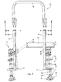
Fig. 1 is a perspective view of a ROPS member mounted on a vehicle axle housing according to the present invention; -
Fig. 2 is a perspective view showing the ROPS mounting assembly ofFig. 1 together with a seat and fender assembly; -
Fig. 3 is a perspective exploded view showing the ROPS mounting assembly ofFig. 1 ; -
Fig. 4 is a detailed perspective exploded view showing a portion of the ROPS mounting assembly ofFig. 1 ; -
Fig. 5 is a detailed perspective assembly view showing the base plate of ROPS mounting assembly ofFig. 1 ; -
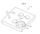
Fig. 6 is a detailed perspective view showing only the base plate of ROPS mounting assembly ofFig. 1 ; and -
Fig. 7 is a sectional view along lines 7-7 ofFig. 5 . - Referring to
Figs. 1 and2 , an invertedU-shaped ROPS unit 10 has a pair oflegs vehicle axle housing 16.ROPS unit 10 includes an inverted U-shapedupper part 18 which is pivotally coupled tolegs Upper part 18 may be pivotally lowered during low clearance transport conditions. A cross piece orbrace 20 extends between and connectslegs assembly 30 is also mounted on theaxle housing 16.Assembly 30 includes a seat andfloor platform 32 and a pair offenders legs adjacent fenders - Referring to
Figs. 3 - 6 , theROPS unit 10 includes a pair ofmounting assemblies base plates legs plates axle housing 16 by the corresponding and complimentary vibrationisolating mounting assembly -
Mounting assembly 44 will be described in detail hereinafter, with the understanding that mountingassembly 45 is similar and may be a mirror image ofmounting assembly 44.Mounting assembly 44 includes asupport 46 which is preferably a cast part.Support 46 includes asupport plate 48 from which project hollow internally threaded fingers ortowers 50. A recess 52 is formed in thesupport plate 48, and abore 54 extends through thesupport plate 48 at or near the center of the recess 52. -
Mounting assembly 44 also includes a bushing unit comprising a lower resilient bushing orisolator 56, an upper resilient bushing orisolator 58 and a hollow rigid, preferably steel,sleeve 60. Bushing 56 is received by recess 52 between thesupport 46 and theplate 42.Plate 42 includes a pair ofdrain holes 62 for cap screws which attach theplate 42 to theleg 14.Plate 42 also includesbores 64 which receive thefingers 50 and abore 66 which receives thebushing 56 and thesleeve 60. A shallowannular recess 68 surrounds bore 66 and receives the lower end of bushing 58. Bore 66 receives a reduceddiameter portion 57 oflower bushing 56. -
Mounting assembly 44 also includes atop plate 70 which mounted over theupper bushing 58 and theplate 42.Top plate 70 includeslower part 71 and aupper part 73.Lower part 71 engages the upper ends of two of thetowers 50.Upper part 73 engages an upper end of the bushing 58.Top plate 70 also includes aspacer tab 75 which projects from theupper part 73.Top plate 70 includesbolt holes 72 which receive threaded members orcap screws Cap screws mounting assembly 44 and are threaded into threadedbores 80 in the upper surface of the axle housing 16 (two of which are visible inFig. 7 ).Cap screws 74 extend throughbolt holes 72, bores 64 and thetowers 50. Theother cap screw 76 extends through one of bolt holes 72,sleeve 60 of the bushing unit, bore 66 and bore 54. Thetowers 50 extend into thebores 64 in thebase plate 42 and the bushing unit is received inbore 60 of thebase plate 42. - As best seen in
Fig. 7 , in a normal non-roll condition, thelower part 71 of thetop plate 70 engages only an upper end of the rear twotowers 50 of thesupport plate 48 and is spaced apart from thebase plate 42. Theupper part 73 of thetop plate 70 engages only theupper isolator 58 and the upper end of thesleeve 60, and is spaced apart from thebase plate 42. The lower end oftab 75 is also spaced apart from thebase plate 42. The fourcap screws top plate 70. Thesupport plate 48 engages and rests on theaxle housing 16 and supports thetop plate 70 andbottom isolator 56. Thebase plate 42, (in a nominal, non-roll condition) only engages thetop isolator 58 and thebottom isolator 56 as it free floats between and spaced apart from thesupport plate 48 and thetop plate 70. - With this mounting assembly, the
ROPS unit 10 is resiliently coupled to theaxle housing 16 and is isolated from theaxle housing 16 with respect to vibration and noise. This mounting assembly is compact, cost effective and meets the necessary roll-over requirements and safety standards (loads & zone of clearance). - In normal operating conditions the
base plate 42 does not contact either the bottom casting 46 or thetop plate 70. A nominal gap is maintained on both sides of theplate 42 which allows them to move up and down for isolation purposes. The bottom casting orsupport 46 mates to therear axle housing 16 and acts as a spacer. Thesupport 46 provides the mounting points (three towers 50) for thetop plate 70, a mounting pad for theisolator bushing 56, and absorbs the reaction loads during a roll-over condition. Thetop plate 70 is bolted to thetowers 50 of thesupport 46. Thetop plate 70 engages the top portion of the upper isolator orbushing 58. The cap screws 74, 76 engage the upper surface of thetop plate 70, which supports the reaction loads during a roll-over condition. Each mounting assembly includes fourcap screws ROPS unit 10. - While the present invention has been described in conjunction with a specific embodiment, it is understood that many alternatives, modifications and variations will be apparent to those skilled in the art in light of the foregoing description. Accordingly, this invention is intended to embrace all such alternatives, modifications and variations which fall within the spirit and scope of the appended claims.
Claims (11)
- A Roll-over protection structure (10) (ROPS), comprising a pair of legs (12, 14) and a pair of mounting assemblies (44, 45) for mounting the ROPS (10) to a part of a vehicle, the mounting assembly (44, 45) comprising a base plate (40, 42) fixed to an end of a corresponding leg (12, 14), characterized in that the mounting assembly (44, 45) comprises further: a support plate (48) fixable with respect to a part of a vehicle; a top plate (70) fixable with respect to a part of a vehicle, the base plate (40,42) being sandwiched between the support plate (48) and the top plate (70); and a resilient bushing unit resiliently coupling the base plate (40, 42) to the support plate (48) and the top plate (70).
- The ROPS (10) of claim 1, wherein: the bushing unit comprises a first resilient bushing member (56) separating the base plate (40, 42) from the support plate (48), and a second resilient bushing member (58) separating the base plate (40, 42) from the top plate (70).
- The ROPS (10) of claim 2, wherein: the bushing unit further comprises a rigid hollow sleeve (60) which is received by the first and second resilient bushing members (56, 58).
- The ROPS (10) of claim 2 or 3, wherein: one of the first and second bushing members (56, 58) comprises a larger diameter cylindrical base and a reduced diameter cylindrical portion (57) projecting therefrom, the reduced diameter portion (57) being received by a bore (66) in the base plate (40, 42).
- The ROPS (10) of one of the claims 2 to 4, wherein: one of the first and second bushing members (56, 58) comprises an annular member which is partially received by a recess (68) in the base plate (40, 42).
- The ROPS (10) of claim 4 or 5, wherein: a plurality of threaded members (74, 76) for fastening the top plate (70) and the support plate (48) to a part of a vehicle, one of the threaded members (76) extending through the hollow sleeve (60), the first and second bushing members (56, 58) and the bushing bore (66).
- The ROPS (10) of one of the claims 1 to 6, wherein: a plurality of mounting bores (64) extend through the base plate (40, 42); and the support plate (48) includes a plurality of hollow mounting towers (50), each tower (50) projecting into a corresponding one of the mounting bores (64).
- The ROPS (10) of claim 7, wherein: threaded members (74) for fastening the top plate (70) and the support plate (48) to a part of a vehicle extending through the top plate (70) and a corresponding one of the towers (50).
- The ROPS (10) of one of the claims 1 to 8, wherein the top plate (70) comprises a tab (75) projecting from the top plate (70), the tab (75) normally being spaced apart from the base plate (40, 42), the tab (75) being engagable with the base plate (40,42) under a roll-over condition.
- The ROPS (10) of one of the claims 1 to 9, wherein the top plate (70) comprises: a lower part (71) engaging the base plate (40, 42); an upper part (73) engaging the bushing unit.
- The ROPS (10) of one of the claims 7 to 10, wherein the top plate (70) engaging an end of the towers (50).
Applications Claiming Priority (1)
| Application Number | Priority Date | Filing Date | Title |
|---|---|---|---|
| US12/361,932 US8029019B2 (en) | 2009-01-29 | 2009-01-29 | ROPS mounting assembly |
Publications (1)
| Publication Number | Publication Date |
|---|---|
| EP2213554A1 true EP2213554A1 (en) | 2010-08-04 |
Family
ID=41648794
Family Applications (1)
| Application Number | Title | Priority Date | Filing Date |
|---|---|---|---|
| EP09178937A Withdrawn EP2213554A1 (en) | 2009-01-29 | 2009-12-11 | Roll-over protection structure |
Country Status (3)
| Country | Link |
|---|---|
| US (1) | US8029019B2 (en) |
| EP (1) | EP2213554A1 (en) |
| JP (1) | JP2010173632A (en) |
Families Citing this family (19)
| Publication number | Priority date | Publication date | Assignee | Title |
|---|---|---|---|---|
| US20100314908A1 (en) * | 2009-06-10 | 2010-12-16 | Wood Jr Robert Lee | Cab frame beltline member |
| US7971905B2 (en) * | 2009-10-23 | 2011-07-05 | Deere & Company | Folding rollover protection system |
| US8905434B1 (en) | 2009-11-12 | 2014-12-09 | Excel Industries, Inc. | Rollover protection apparatus |
| US10377333B2 (en) | 2009-11-12 | 2019-08-13 | Excel Industries, Inc. | Deployable operator protection apparatus with an over-center linkage |
| US11724658B2 (en) | 2009-11-12 | 2023-08-15 | Excel Industries, Inc. | Control system for a terrain working vehicle having an operator protection apparatus |
| US10493939B2 (en) | 2015-02-13 | 2019-12-03 | Excel Industries, Inc. | Lever-actuated operator protection apparatus |
| US9573548B2 (en) | 2015-02-13 | 2017-02-21 | Excel Industries, Inc. | Operator protection apparatus with an over-center linkage |
| US11198408B2 (en) | 2009-11-12 | 2021-12-14 | Excel Industries, Inc. | Control system for a terrain working vehicle having an operator protection apparatus |
| JP5588207B2 (en) * | 2010-03-24 | 2014-09-10 | 株式会社クボタ | Tractor |
| US8523225B2 (en) * | 2010-10-27 | 2013-09-03 | Custom Products Of Litchfield, Inc. | Overhead frame structure system |
| KR101876886B1 (en) * | 2014-05-29 | 2018-07-11 | 대동공업주식회사 | Rear axle case of an agriculture vehicle and Rear axle assembly of an agriculture vehicle |
| US9616837B1 (en) | 2014-06-03 | 2017-04-11 | Excel Industries, Inc. | Forward folding roll bar assembly |
| WO2014185553A1 (en) * | 2014-06-30 | 2014-11-20 | 株式会社小松製作所 | Utility vehicle |
| JP6494501B2 (en) * | 2015-12-15 | 2019-04-03 | 株式会社クボタ | Work vehicle |
| CN106184100B (en) * | 2016-07-01 | 2018-07-03 | 江苏科技大学 | A kind of automatic collapsible type rolling protective device for sitting type grass trimmer |
| US9981545B1 (en) * | 2017-03-29 | 2018-05-29 | Deere & Company | Zero turning radius mower radiator mounting structure |
| US10696260B2 (en) | 2017-10-30 | 2020-06-30 | Deere & Company | Multiple pivot rollover protection structure |
| JP7150081B1 (en) * | 2021-03-29 | 2022-10-07 | 株式会社クボタ | work vehicle |
| JP7635655B2 (en) * | 2021-06-30 | 2025-02-26 | 井関農機株式会社 | Work vehicles |
Citations (3)
| Publication number | Priority date | Publication date | Assignee | Title |
|---|---|---|---|---|
| US3656799A (en) * | 1970-04-14 | 1972-04-18 | Deere & Co | Vibration isolated unitary cab and control console construction for a tractor |
| US5388884A (en) * | 1993-04-21 | 1995-02-14 | Caterpillar Inc. | Arrangement for mounting a cab structure to a vehicle frame |
| JP2001206178A (en) * | 2000-01-21 | 2001-07-31 | Kubota Corp | Rope device for traveling vehicles |
Family Cites Families (13)
| Publication number | Priority date | Publication date | Assignee | Title |
|---|---|---|---|---|
| US2546453A (en) | 1947-06-09 | 1951-03-27 | Koenig Adolph | Adjustable tractor wheel means |
| US3443833A (en) | 1967-03-10 | 1969-05-13 | Deere & Co | Safety enclosure for tractors |
| US3656803A (en) * | 1970-08-27 | 1972-04-18 | Deere & Co | Tractor roll bar |
| US3732941A (en) | 1971-05-18 | 1973-05-15 | Allis Chalmers | Vehicle chassis resiliently supported on main frame |
| US3791668A (en) | 1972-06-14 | 1974-02-12 | Caterpillar Tractor Co | Roll-over protection structure with deformable legs |
| US3985386A (en) | 1975-09-15 | 1976-10-12 | Deere & Company | Vehicle roll-over protective structure |
| US4049294A (en) * | 1975-12-22 | 1977-09-20 | Allis-Chalmers Corporation | Narrow base protective frame |
| ATE22045T1 (en) | 1984-01-30 | 1986-09-15 | Deere & Co | DRIVER'S CAB FOR ONE VEHICLE. |
| US4669565A (en) | 1984-12-20 | 1987-06-02 | Kubota, Ltd. | Agricultural tractor with a driver's cabin |
| US4877265A (en) | 1988-07-29 | 1989-10-31 | Deere & Company | Adjustable height vehicle roll-over bar |
| US5129676A (en) * | 1991-02-19 | 1992-07-14 | Ford New Holland, Inc. | Counterbalanced telescopic rollbar for tractors |
| US7396047B1 (en) | 2004-07-14 | 2008-07-08 | Femco, Inc. | Ride-on turf mowing machine rollover protection assembly |
| US7438319B2 (en) | 2006-02-09 | 2008-10-21 | Bruce Russell Lee Cooper | Modular roll protection structure (ROPS) for compact tractors |
-
2009
- 2009-01-29 US US12/361,932 patent/US8029019B2/en active Active
- 2009-12-11 EP EP09178937A patent/EP2213554A1/en not_active Withdrawn
-
2010
- 2010-01-26 JP JP2010013970A patent/JP2010173632A/en active Pending
Patent Citations (3)
| Publication number | Priority date | Publication date | Assignee | Title |
|---|---|---|---|---|
| US3656799A (en) * | 1970-04-14 | 1972-04-18 | Deere & Co | Vibration isolated unitary cab and control console construction for a tractor |
| US5388884A (en) * | 1993-04-21 | 1995-02-14 | Caterpillar Inc. | Arrangement for mounting a cab structure to a vehicle frame |
| JP2001206178A (en) * | 2000-01-21 | 2001-07-31 | Kubota Corp | Rope device for traveling vehicles |
Also Published As
| Publication number | Publication date |
|---|---|
| JP2010173632A (en) | 2010-08-12 |
| US8029019B2 (en) | 2011-10-04 |
| US20100187799A1 (en) | 2010-07-29 |
Similar Documents
| Publication | Publication Date | Title |
|---|---|---|
| US8029019B2 (en) | ROPS mounting assembly | |
| US5388884A (en) | Arrangement for mounting a cab structure to a vehicle frame | |
| US3940177A (en) | Vibration-isolated cab for tractors | |
| US3560019A (en) | Shock cushioning mounting means for canopies on heavy equipment | |
| CA1101013A (en) | Operator's compartment and seat mounting | |
| US4061392A (en) | Side tilt integrated cab | |
| US20050000121A1 (en) | Construction equipment | |
| US7175190B2 (en) | Horizontal mount of suspension element to axle | |
| CA1055990A (en) | Platform-operator tilting resilient mounting for earthmoving vehicles | |
| US3612581A (en) | Canopy mount | |
| US3438672A (en) | Isolated platform mounting | |
| US3834754A (en) | Isolated tractor platform | |
| US3873222A (en) | Roll-over protective structure mounting | |
| US4174117A (en) | Isolated step support | |
| US2955844A (en) | Universal attachment support for tractors | |
| KR101548583B1 (en) | Lower part machinery mounting bracket and rail vehicle having the same | |
| JP3072295B1 (en) | Side collision safety device for automobiles | |
| JP2004197550A (en) | Work vehicle | |
| US4116412A (en) | Resilient mounting for an operator's station on a vehicle | |
| KR102344932B1 (en) | Device for supporting cabins of tractors | |
| JP2931357B2 (en) | Safety frame | |
| JPS5936971Y2 (en) | tractor | |
| US4966402A (en) | Aerial lift support frame | |
| JP4333921B2 (en) | Work vehicle | |
| JP2519662Y2 (en) | Cab mounting device |
Legal Events
| Date | Code | Title | Description |
|---|---|---|---|
| PUAI | Public reference made under article 153(3) epc to a published international application that has entered the european phase |
Free format text: ORIGINAL CODE: 0009012 |
|
| AK | Designated contracting states |
Kind code of ref document: A1 Designated state(s): AT BE BG CH CY CZ DE DK EE ES FI FR GB GR HR HU IE IS IT LI LT LU LV MC MK MT NL NO PL PT RO SE SI SK SM TR |
|
| AX | Request for extension of the european patent |
Extension state: AL BA RS |
|
| STAA | Information on the status of an ep patent application or granted ep patent |
Free format text: STATUS: THE APPLICATION HAS BEEN WITHDRAWN |
|
| 18W | Application withdrawn |
Effective date: 20101104 |