EP2213455A1 - Liquid ejecting apparatus and liquid ejecting method - Google Patents
Liquid ejecting apparatus and liquid ejecting method Download PDFInfo
- Publication number
- EP2213455A1 EP2213455A1 EP10000870A EP10000870A EP2213455A1 EP 2213455 A1 EP2213455 A1 EP 2213455A1 EP 10000870 A EP10000870 A EP 10000870A EP 10000870 A EP10000870 A EP 10000870A EP 2213455 A1 EP2213455 A1 EP 2213455A1
- Authority
- EP
- European Patent Office
- Prior art keywords
- temperature
- liquid
- head
- correction table
- liquid ejecting
- Prior art date
- Legal status (The legal status is an assumption and is not a legal conclusion. Google has not performed a legal analysis and makes no representation as to the accuracy of the status listed.)
- Granted
Links
Images





Classifications
-
- B—PERFORMING OPERATIONS; TRANSPORTING
- B41—PRINTING; LINING MACHINES; TYPEWRITERS; STAMPS
- B41J—TYPEWRITERS; SELECTIVE PRINTING MECHANISMS, i.e. MECHANISMS PRINTING OTHERWISE THAN FROM A FORME; CORRECTION OF TYPOGRAPHICAL ERRORS
- B41J2/00—Typewriters or selective printing mechanisms characterised by the printing or marking process for which they are designed
- B41J2/005—Typewriters or selective printing mechanisms characterised by the printing or marking process for which they are designed characterised by bringing liquid or particles selectively into contact with a printing material
- B41J2/01—Ink jet
- B41J2/015—Ink jet characterised by the jet generation process
- B41J2/04—Ink jet characterised by the jet generation process generating single droplets or particles on demand
- B41J2/045—Ink jet characterised by the jet generation process generating single droplets or particles on demand by pressure, e.g. electromechanical transducers
- B41J2/04501—Control methods or devices therefor, e.g. driver circuits, control circuits
- B41J2/0459—Height of the driving signal being adjusted
-
- B—PERFORMING OPERATIONS; TRANSPORTING
- B41—PRINTING; LINING MACHINES; TYPEWRITERS; STAMPS
- B41J—TYPEWRITERS; SELECTIVE PRINTING MECHANISMS, i.e. MECHANISMS PRINTING OTHERWISE THAN FROM A FORME; CORRECTION OF TYPOGRAPHICAL ERRORS
- B41J2/00—Typewriters or selective printing mechanisms characterised by the printing or marking process for which they are designed
- B41J2/005—Typewriters or selective printing mechanisms characterised by the printing or marking process for which they are designed characterised by bringing liquid or particles selectively into contact with a printing material
- B41J2/01—Ink jet
- B41J2/015—Ink jet characterised by the jet generation process
- B41J2/04—Ink jet characterised by the jet generation process generating single droplets or particles on demand
- B41J2/045—Ink jet characterised by the jet generation process generating single droplets or particles on demand by pressure, e.g. electromechanical transducers
- B41J2/04501—Control methods or devices therefor, e.g. driver circuits, control circuits
- B41J2/04508—Control methods or devices therefor, e.g. driver circuits, control circuits aiming at correcting other parameters
-
- B—PERFORMING OPERATIONS; TRANSPORTING
- B41—PRINTING; LINING MACHINES; TYPEWRITERS; STAMPS
- B41J—TYPEWRITERS; SELECTIVE PRINTING MECHANISMS, i.e. MECHANISMS PRINTING OTHERWISE THAN FROM A FORME; CORRECTION OF TYPOGRAPHICAL ERRORS
- B41J2/00—Typewriters or selective printing mechanisms characterised by the printing or marking process for which they are designed
- B41J2/005—Typewriters or selective printing mechanisms characterised by the printing or marking process for which they are designed characterised by bringing liquid or particles selectively into contact with a printing material
- B41J2/01—Ink jet
- B41J2/015—Ink jet characterised by the jet generation process
- B41J2/04—Ink jet characterised by the jet generation process generating single droplets or particles on demand
- B41J2/045—Ink jet characterised by the jet generation process generating single droplets or particles on demand by pressure, e.g. electromechanical transducers
- B41J2/04501—Control methods or devices therefor, e.g. driver circuits, control circuits
- B41J2/0454—Control methods or devices therefor, e.g. driver circuits, control circuits involving calculation of temperature
-
- B—PERFORMING OPERATIONS; TRANSPORTING
- B41—PRINTING; LINING MACHINES; TYPEWRITERS; STAMPS
- B41J—TYPEWRITERS; SELECTIVE PRINTING MECHANISMS, i.e. MECHANISMS PRINTING OTHERWISE THAN FROM A FORME; CORRECTION OF TYPOGRAPHICAL ERRORS
- B41J2/00—Typewriters or selective printing mechanisms characterised by the printing or marking process for which they are designed
- B41J2/005—Typewriters or selective printing mechanisms characterised by the printing or marking process for which they are designed characterised by bringing liquid or particles selectively into contact with a printing material
- B41J2/01—Ink jet
- B41J2/015—Ink jet characterised by the jet generation process
- B41J2/04—Ink jet characterised by the jet generation process generating single droplets or particles on demand
- B41J2/045—Ink jet characterised by the jet generation process generating single droplets or particles on demand by pressure, e.g. electromechanical transducers
- B41J2/04501—Control methods or devices therefor, e.g. driver circuits, control circuits
- B41J2/04553—Control methods or devices therefor, e.g. driver circuits, control circuits detecting ambient temperature
-
- B—PERFORMING OPERATIONS; TRANSPORTING
- B41—PRINTING; LINING MACHINES; TYPEWRITERS; STAMPS
- B41J—TYPEWRITERS; SELECTIVE PRINTING MECHANISMS, i.e. MECHANISMS PRINTING OTHERWISE THAN FROM A FORME; CORRECTION OF TYPOGRAPHICAL ERRORS
- B41J2/00—Typewriters or selective printing mechanisms characterised by the printing or marking process for which they are designed
- B41J2/005—Typewriters or selective printing mechanisms characterised by the printing or marking process for which they are designed characterised by bringing liquid or particles selectively into contact with a printing material
- B41J2/01—Ink jet
- B41J2/015—Ink jet characterised by the jet generation process
- B41J2/04—Ink jet characterised by the jet generation process generating single droplets or particles on demand
- B41J2/045—Ink jet characterised by the jet generation process generating single droplets or particles on demand by pressure, e.g. electromechanical transducers
- B41J2/04501—Control methods or devices therefor, e.g. driver circuits, control circuits
- B41J2/04563—Control methods or devices therefor, e.g. driver circuits, control circuits detecting head temperature; Ink temperature
-
- B—PERFORMING OPERATIONS; TRANSPORTING
- B41—PRINTING; LINING MACHINES; TYPEWRITERS; STAMPS
- B41J—TYPEWRITERS; SELECTIVE PRINTING MECHANISMS, i.e. MECHANISMS PRINTING OTHERWISE THAN FROM A FORME; CORRECTION OF TYPOGRAPHICAL ERRORS
- B41J2/00—Typewriters or selective printing mechanisms characterised by the printing or marking process for which they are designed
- B41J2/005—Typewriters or selective printing mechanisms characterised by the printing or marking process for which they are designed characterised by bringing liquid or particles selectively into contact with a printing material
- B41J2/01—Ink jet
- B41J2/015—Ink jet characterised by the jet generation process
- B41J2/04—Ink jet characterised by the jet generation process generating single droplets or particles on demand
- B41J2/045—Ink jet characterised by the jet generation process generating single droplets or particles on demand by pressure, e.g. electromechanical transducers
- B41J2/04501—Control methods or devices therefor, e.g. driver circuits, control circuits
- B41J2/04581—Control methods or devices therefor, e.g. driver circuits, control circuits controlling heads based on piezoelectric elements
-
- B—PERFORMING OPERATIONS; TRANSPORTING
- B41—PRINTING; LINING MACHINES; TYPEWRITERS; STAMPS
- B41J—TYPEWRITERS; SELECTIVE PRINTING MECHANISMS, i.e. MECHANISMS PRINTING OTHERWISE THAN FROM A FORME; CORRECTION OF TYPOGRAPHICAL ERRORS
- B41J2/00—Typewriters or selective printing mechanisms characterised by the printing or marking process for which they are designed
- B41J2/005—Typewriters or selective printing mechanisms characterised by the printing or marking process for which they are designed characterised by bringing liquid or particles selectively into contact with a printing material
- B41J2/01—Ink jet
- B41J2/015—Ink jet characterised by the jet generation process
- B41J2/04—Ink jet characterised by the jet generation process generating single droplets or particles on demand
- B41J2/045—Ink jet characterised by the jet generation process generating single droplets or particles on demand by pressure, e.g. electromechanical transducers
- B41J2/04501—Control methods or devices therefor, e.g. driver circuits, control circuits
- B41J2/04588—Control methods or devices therefor, e.g. driver circuits, control circuits using a specific waveform
Definitions
- the present invention relates to a liquid ejecting apparatus and a liquid ejecting method.
- An ink jet printer includes a heating mechanism which is disposed near a printing head and executes drying the print surface of a print medium such as a sheet.
- a heating mechanism which is disposed near a printing head and executes drying the print surface of a print medium such as a sheet.
- a printer including a large-scale printing head called a line head executes printing at a high speed, it is necessary for a heating mechanism to dry the print surface of a print medium.
- JP-A-6-182997 discloses a technique in which a head thermistor is used as the temperature detecting unit to correct the head driving waveform of the printing head on the basis of a detection temperature of the head thermistor.
- the head driving waveform of the printing head is corrected on the basis of the detection temperature of the head thermistor.
- the ink is a liquid and an increase in the temperature is gentle due to a specific heat capacity.
- the detection temperature of the head thermistor is easily higher than an actual temperature of the ink.
- a great gap between the actual temperature of the ink and the detection temperature of the thermistor may occur in some cases.
- the heating mechanism is interrupted only once, the actual temperature of the ink is decreased. Therefore, a greater gap between the actual temperature of the ink and the detection temperature of the thermistor may occur. As a consequence, it is more difficult to appropriately correct the head driving waveform of the printing head.
- An advantage of some aspects of the invention there is provided a liquid ejecting apparatus and a liquid ejecting method capable of correcting a head driving waveform of a liquid ejecting head to an appropriate head driving waveform, even when a heating mechanism is interrupted.
- a liquid ejecting apparatus including: a liquid ejecting head which ejects a liquid from a nozzle to an ejection medium; a heating unit which heats and dries the liquid ejected to the ejection medium; a temperature measuring unit which is disposed at a predetermined region near the liquid ejecting head and measures a temperature of the predetermined region; a temperature calculating unit which calculates a temperature of the liquid ejected from the liquid ejecting head on the basis of an initial temperature measurement result of the temperature measuring unit and on the basis of a temperature correction table associating time elapsed after operation of the heating unit with a temperature of the liquid at the time elapsed and which calculates a temperature of the liquid to be ejected from the liquid ejecting head on the basis of a descending correction table associating a difference between a temperature immediately after interruption of the heating unit and an outside ambient temperature with an interruption time; and a driving waveform correcting
- the outside ambient temperature may be measured by an ambient temperature measuring unit.
- the temperature calculating unit may calculate a temperature of the liquid on the basis of the descending correction table, and may continuously calculate a temperature of the liquid to be ejected from the liquid ejecting head on the basis of an ascending correction table associating a difference between a temperature elapsed immediately after the operation of the heating unit and a saturation temperature upon heating the liquid with operation time, when the heating unit again operates from the interrupted state.
- the temperature correction table, the descending correction table, or the ascending correction table may be present for every predetermined temperature.
- a temperature between the predetermined temperatures is the initial temperature measurement result of the temperature measuring unit
- the temperature correction table, the descending correction table, or the ascending correction table between the predetermined temperatures may be calculated by linear interpolation.
- the liquid ejecting head may be a line head in which a plurality of head main bodies is arranged.
- the temperature correction table may be present for each of the head main bodies.
- a method of ejecting a liquid using a liquid ejecting head which ejects the liquid from a nozzle passage and a heating unit which heats and dries the liquid ejected to an ejection medium, so as to respond to a variation in a temperature depending on an operation of the heating unit.
- the method includes: measuring an initial temperature by a temperature measuring unit which is disposed at a predetermined region near the liquid ejecting head and which measures a temperature of the predetermined region; calculating a temperature of the liquid ejected from the liquid ejecting head on the basis of an initial temperature measurement result in the measuring of the initial temperature and on the basis of a temperature correction table associating time elapsed after operation of the heating unit with a temperature of the liquid at the time elapsed, and calculating a temperature of the liquid to be ejected from the liquid ejecting head on the basis of a descending correction table associating a difference between a temperature immediately after interruption of the heating unit and an outside ambient temperature with an interruption time; and correcting a head driving waveform of the liquid ejecting head on the basis of a calculation result of the temperature of the liquid by the calculating of the temperature.
- Fig. 1 is a diagram illustrating the overall configuration of a printer according to an embodiment of the invention.
- Fig. 2 is a sectional view illustrating the configuration of a line head.
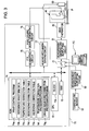
- Fig. 3 is a block diagram illustrating the overall configuration of a controller and peripheral units connected to the controller.
- Fig. 4 is a diagram illustrating an example of a temperature correction table.
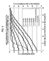
- Fig. 5 is a graph illustrating a relationship between a variation in the temperature and elapsed time.
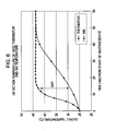
- Fig. 6 is a graph illustrating a difference between the temperature detected in a head thermistor and the temperature of ink.
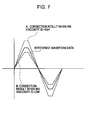
- Fig. 7 is a diagram illustrating the correction of a head driving waveform.
- Fig. 8 is a graph illustrating a relationship between a variation in temperature based on a table and elapsed time.
- Fig. 9 is a diagram illustrating an example of a descending correction table.
- Fig. 10 is a diagram illustrating an example of an ascending correction table.
- a printer 10 which is a liquid ejecting apparatus, according to an embodiment of the invention will be described with reference to Figs. 1 to 7 .
- Fig. 1 is a schematic diagram illustrating the overall configuration of the printer 10 according to the embodiment of the invention.
- the printer 10 according to this embodiment includes a sheet feeding mechanism 20, an ink supplying mechanism 30, the line head 40, a head thermistor 50, and a heating mechanism 60, and a controller 70 as main elements.
- the sheet feeding mechanism 20 includes a sheet feeding motor (PF motor) 21 and a feeding roller 22 to which a driving force is transferred from the sheet feeding motor 21.
- the ink supplying mechanism 30 includes a cartridge holder 31, a pressurizing pump 32, an ink supply passage 33, an ink cartridge 34.
- the cartridge holder 31 is mounted in a chassis (not shown), for example.
- the ink cartridge 34 is detachably mounted on the cartridge holder 31. Accordingly, the printer 10 according to this embodiment has a so-called off-carriage type configuration.
- the pressuring pump 32 When ink (corresponding to a liquid) is supplied, the pressuring pump 32 operates to pump air into the inside of the ink cartridge 34, press an ink pack, and eject the ink to the ink supply passage 33.
- the line head 40 corresponds to a liquid ejecting head. As shown in Fig. 2 , the line head 40 includes a head main body 41 and a nozzle plate 42. Pressure generating chambers 411, a reservoir 412, and piezoelectric elements 413 are formed in the head main body 41 by appropriately etching a silicon substrate or the like.
- the nozzle plate 42 is made of SUS (Stainless Used Steel), for example. Nozzles 420 are punched in the nozzle plate 42. When the nozzle plate 42 is mounted in the head main body 41, the nozzles 420 communicate with pressure generating chambers (not shown) so as to eject the ink.
- the head main body 41 In the line head 40, the head main body 41, with a longitudinal shape may be disposed or a plurality of relatively small head main bodies may be arranged in zigzags.
- the head thermistor 50 is mounted on a predetermined substrate (a head driving signal generating circuit 76 or another processing circuit) of the line head 40.
- the head thermistor 50 which corresponds to a temperature measuring unit, is a unit which measures the temperature of the line head 40.
- An installation region (corresponding to a predetermined region) of the head thermistor 50 may be a predetermined substrate.
- the head thermistor 50 may be directly attached to the head main body 41 of the line head 40.
- the head thermistor 50 is attached to the rear surface of the line head 40 on the upstream side in a sheet feeding direction.
- the installation region of the head thermistor 50 is not limited thereto.
- the head thermistor 50 may be attached to the side surface of the line head 40, the front surface of the line head 40, or the like.
- the number of the head thermistor 50 arranged is not limited to one, but plural head thermistors may be arranged at an appropriate interval.
- the line head 40 includes a plurality of relatively small head main bodies 41
- the head thermistor 50 may be attached to each of the head main bodies 41.
- a temperature correction table 74c which is described below, is present in each of the relatively small head main bodies 41. Therefore, the temperature of the ink can be corrected more precisely.
- the head thermistor 50 is connected to a measurement temperature outputting circuit 51.
- the measurement temperature outputting circuit 51 digitalizes and outputs a voltage value or a current value (referred to as a measurement value) corresponding to the electric resistance of the head thermistor 50. Then, the output measurement value is input to the controller 70 which is described below.
- a thermocouple a semiconductor temperature sensor, a linear resistor, a platinum resistance temperature detector, or the like may be used in addition to the head thermistor 50.
- a temperature sensor 52 (corresponding to an ambient temperature measuring unit) is mounted in the printer 10.
- the temperature sensor 52 is a unit which measures the outside ambient temperature of the printer 10.
- the temperature sensor 52 is connected to a measurement temperature outputting circuit 53 and the analog measurement value measured by the temperature sensor 52 is digitalized and output to the controller 70.
- a thermistor similar to the head thermistor 50 may be used or a thermocouple, a semiconductor temperature sensor, a linear resistor, a platinum resistance temperature detector, or the like may be used.
- the heating mechanism 60 corresponds to a heating unit.
- the heating mechanism 60 is a unit which heats and dries the print surface of a print medium P (corresponding to an ejection medium) subjected to printing by the line head 40, as shown in Figs. 1 and 3 .
- the heating mechanism 60 has a dimension so as to heat and dry the whole size of the print medium P in a width direction of the print medium P.
- a mechanism which radiates microwaves to the print surface to heat and dry the print surface may be used as the heating mechanism 60.
- a unit which blows a hot wind to dry the print surface or a unit which heats a roller and brings the print medium P into contact with the roller to dry ink ejected to the print surface may be used.
- the controller 70 includes a communication interface 71, a CPU 72, a RAM 73, a ROM 74, a PTS generating circuit 75, a head driving signal generating circuit 76, and a heating mechanism driving circuit 77.
- the communication interface 71 is a circuit which executes communication with a computer PC.
- the CPU 72 reads various data or various programs and executes various processing operations in accordance with the various programs.
- the CPU 72 has a clock 72a therein.
- the clock 72a generates a clock signal CL serving as a reference of PTS generated by the PTS generating circuit 75 which is described below.
- the RAM 73 is a memory which temporarily stores various data.
- the ROM 74 stores various programs or various data. Therefore, even when the power of the printer 10 is turned off, the programs or the data are maintained.
- the programs stored in the ROM 74 include a print control program 74a used to operate each unit of the printer 10 and a reference waveform data 74b of a head driving signal which is described below.
- the ROM 74 also stores a temperature correction table 74c (see Figs. 4 and 5 , etc.) used to execute temperature correction (temperature calculation), which is described below, on the basis of a temperature measurement value output from the above-described measurement temperature outputting circuit 51.
- the ROM 74 stores a descending correction table 74d and an ascending correction table 74e used to execute the same temperature correction (temperature calculating).
- the ROM 74 stores a temperature correction processing program 74f used to correct the temperature of the line head 40 on the basis of the temperature correction table 74c, the descending correction table 74d, or the ascending correction table 74e stored in the ROM 74.
- the ROM 74 stores a head driving waveform correction processing program 74g used to generate (execute temperature correction) correction waveform data by correcting the reference waveform data 74b stored in the ROM 74 on the basis of the result of the temperature correction.
- a temperature calculating unit is functionally executed.
- a driving waveform correcting unit is functionally executed.
- the temperature correction table 74c shown in Figs. 4 and 5 is prepared on the basis of the result obtained by measuring the temperature of ink or the temperature in effect near the nozzles 420 by a non-contact type sensor, for example, when the heating mechanism 60 is operated. That is, the temperature measured upon initiating the operation of the heating mechanism 60 is the same as the outside ambient temperature and the temperature input via the head thermistor 50 and the measurement temperature outputting circuit 51.
- the temperature correction table 74c is prepared on the basis of the result obtained by measuring the temperature near the nozzles 420 in effect by the non-contact type sensor at every predetermined time from the initiation of the operation.
- the initial values of the temperature are present at an interval of 5°C in the temperature correction table 74c. Therefore, when an initially measured temperature value is a temperature between intervals, a pseudo-temperature correction table 74c may be calculated by a linear interpolation method or the like. In the temperature correction table 74c, as shown in Figs. 4 and 5 , the initial values of the temperature may not be present at an interval of 5°C. However, the initial values of the temperature may be present at an interval of 1°C, for example, or may be present at a larger interval conversely.
- the descending correction table 74d and the ascending correction table 74e are prepared on the basis of the result obtained by measuring the temperature of ink or the temperature near the nozzles 420 in effect by a non-contact type sensor, for example, when the heating mechanism 60 is interrupted or the heating mechanism 60 is operated again (see Figs. 9 and 10 ).
- a variation in the temperature of the ink is uniquely determined by what degree ⁇ T is.
- ⁇ T is a difference between an outside ambient temperature T1 and a temperature obtained immediately after the heating mechanism 60 is interrupted.
- a variation of the temperature of the ink is uniquely determined by what degree ⁇ T is.
- ⁇ T is a difference between a saturation temperature Ts and a temperature obtained immediately after the heating mechanism 60 is operated again.
- ⁇ T is present at an interval of 5°C. Therefore, when an initially measured temperature value is present between the intervals, a pseudo-descending correction table and a pseudo-ascending correction table may be calculated by a linear interpolation method or the like.
- the initial values of the temperature may not be present at an interval of 5°C. However, the initial values of the temperature may be present at a precise interval such as an interval of 1°C, or may be present at a larger interval conversely.
- the PTS generating circuit 75 generates a print timing signal (hereinafter, abbreviated to as PTS) of the line head 40.
- PTS print timing signal
- An encoder signal from a linear encoder (not shown), the clock signal CL from the above-described clock, PTS generation information based on the image data processed by the CPU 71 are input to the PTS generation circuit 75.
- a reference PTS is generated on the basis of the signals.
- the head driving signal generating circuit 76 generates the head driving signal in synchronization with the reference PTS generated by the PTS generation circuit 75.
- the temperature correction processing program 74f executed by the CPU 72 does not use the temperature measurement value output from the measurement temperature outputting circuit 51 but uses the temperature determined in the temperature correction table 74c, until the heating mechanism 60 is initially operated and the temperature is saturated.
- the head driving waveform correction processing program 74g corrects the reference waveform data 74b to generate the correction waveform data on the basis of the result of the temperature correction.
- the correction waveform data is input to the head driving signal generating circuit 76 and the head driving signal generating circuit 76 generates the head driving signal in synchronization with the reference PTS on the basis of the correction waveform data.
- the heating mechanism driving circuit 77 is a circuit which controls the operation of the heating mechanism 60 on the basis of an instruction from the CPU 72. Moreover, the heating mechanism driving circuit 77 may control the heating mechanism 60 so that the heating mechanism 60 is typically operated during the operation of the printer 10 or so that the heating mechanism 60 is operated when an image is printed on the print medium P.
- the correction of the temperature measured in the head thermistor 50 and the correction of the head driving waveform in the line head 40 are executed as follows, when the heating mechanism 60 is not interrupted.
- the temperature (in particular, the initial measurement value of the temperature) of the line head 40 is input to the controller 70 (the CPU 72) via the head thermistor 50 and the measurement temperature outputting circuit 51.
- the CPU 72 executes the temperature correction processing program 74f.
- the vicinity of the head thermistor 50 mounted on the predetermined substrate of the line head 40 is easily heated by the operation of the heating mechanism 60.
- the ink is a liquid and an increase in the temperature is gentle due to a specific heat capacity.
- a great gap between the detection temperature of the head thermistor 50 and an actual temperature of the ink occurs until the temperature of the ink is saturated, compared to the actual temperature of the ink.
- a great gap between the actual temperature of the ink and the detection temperature of the thermistor occurs.
- the temperature correction is executed on the temperature measurement value output from the measurement temperature outputting circuit 51 on the basis of the temperature correction table 74c and the temperature correction processing program 74f.
- the temperature correction table 74c to be used is determined among the temperature correction tables 74c on the basis of a measured initial temperature value T0 of the output from the measurement temperature outputting circuit 51.
- Fig. 5 is a graph illustrating a relationship between a variation in the temperature and elapsed time in the temperature correction table 74c.
- the plural temperature correction tables 74c for the temperature are graphed.
- the temperature correction table 74c corresponding to one measured initial temperature value T0 is uniquely determined among the plural temperature correction tables 74c.
- the temperature correction processing program 74f calculates the current temperature of the ink on the basis of the relationship between the used temperature correction table 74c and the elapsed time.
- the value of the temperature Ti is not calculated on the basis of the temperature measured in the head thermistor 50. Instead, the value of the temperature Ti is calculated after this value is corrected on the basis of the measured initial temperature value T0 measured by the head thermistor 50 and elapsed time S.
- the head driving waveform correction processing program 74g corrects the reference waveform data 74b and generates the corrected head driving waveform. That is, the head driving waveform correction processing program 74g generates correction waveform data.
- the correction waveform data is created and the ink viscosity is varied depending on the temperature. In general, the ink viscosity is increased in a low temperature environment, while the ink viscosity is decreased in a high temperature environment.
- the reference waveform data 74b is corrected so that the correction waveform data is increased (see a correction result indicated by a dashed line A in Fig. 7 ).
- the reference waveform data 74b is corrected so that the correction waveform data is decreased (see a correction result indicated by a one-dot chain line B in Fig. 7 ).
- a correction process may be executed such that a variation in the ink viscosity is measured at high temperature measurement point and low temperature measurement point, the ink viscosity is linearly varied between the high and low temperature measurement points, and the correction wave data is linearly increased or decreased depending on the temperature at a predetermined ratio.
- a correction process may be executed such that the variation in the ink viscosity is measured at every temperature, a correction table is made in accordance with the measured ink viscosity, and the correction wave data is increased or decreased in accordance with the correction table.
- the correction waveform data is input to the head driving signal generating circuit 76 and the head driving signal synchronized with the PTS is generated on the basis of the correction waveform data.
- the line head 40 the piezoelectric elements 413
- the ink is ejected from the nozzles 420.
- the temperature is corrected by the temperature correction table 74c and the temperature correction processing program 74f as in Operation 1 described above. Accordingly, the temperature correction table 74c to be used is determined among the temperature correction tables 74c on the basis of the measured initial temperature value T0 output from the measurement temperature outputting circuit 51. Then, a variation in the temperature shown in area A in Fig. 8 is shown. In the example shown in Fig. 8 , the measured initial temperature value T0 is 25°C.
- Fig. 8 when the temperature of the ink reaches the outside ambient temperature T1 at time Ta (where the temperature of the ink does not drop at time Ta until the outside ambient temperature T1, the heating mechanism 60 is interrupted. Then, the temperature of the ink becomes different from the temperature measured in the head thermistor 50. The temperature of the ink gently drops to be close to the outside ambient temperature T1 of the printer 10.
- Fig. 9 the variation in the temperature is shown in a table (the descending correction table 74d) based on the actual measurement when the temperature of the ink is 44°C and the outside ambient temperature T1 of the printer 10 is in the range from 15°C to 40°C.
- a long one-dot line in Fig. 9 indicates the variation in the temperature measured in the thermistor 50 when the outside ambient temperature is 25°C.
- the temperature measured in the head thermistor 50 sharply drops.
- the temperature of the ink gently drops toward the outside ambient temperature T1 of the printer 10 due to a great specific heat capacity.
- the temperature is calculated using the temperature correction processing program 74f and the descending correction table 74d after time Ta (corresponding to area B) immediately when the heating mechanism 60 is interrupted. In this way, the temperature of the ink in area B can be calculated.
- the heating mechanism 60 is interrupted when the temperature of the ink is 39°C.
- a method of determining one descending correction table 74d among the plural descending correction tables 74d is as follows. First, there is evaluated a difference ⁇ T between the outside ambient temperature T1 and the temperature obtained at time Ta immediately after the heating mechanism 60 is interrupted. In Fig. 8 , the difference ⁇ T in area B is 9°C. A descending correction table representing the variation in the temperature of the ink between the differences ⁇ T is uniquely determined as the descending correction table 74d among the plural descending correction tables 74d.
- the interval of the outside ambient temperature T1 is 5°C. Therefore, when a temperature between the intervals is the outside ambient temperature T1, a pseudo-descending correction table may be calculated by a linear interpolation method or the like.
- the initial values of the temperature may not be present at an interval of 5°C, as shown in Fig. 9 .
- the descending correction tables may be present at a precise interval such as an interval of 1°, or may be present at a larger interval conversely.
- the heating mechanism 60 is operated again at time Tb.
- the temperature is calculated using the temperature correction processing program 74f and the ascending correction table 74e after time Tb (corresponding to area C) at which the heating mechanism 60 is operated again. In this way, the temperature of the ink can be calculated in area C.
- the heating mechanism 60 is operated again when the temperature of the ink is 35°C.
- a method of determining one ascending correction table 74e among the plural ascending correction tables 74e is similar to the above-described method of determining the descending correction table 74d. That is, there is evaluated a difference ⁇ T between the saturation temperature Ts and the temperature obtained at time Tb immediately after the heating mechanism 60 is operated again. In Fig. 8 , the difference ⁇ T in area C is 9°C. An ascending correction table representing the variation in the temperature of the ink between the differences ⁇ T is uniquely determined as the ascending correction table 74e among the plural ascending correction tables 74e shown in Fig. 10 .
- the heating mechanism 60 is interrupted again at time Tc.
- the difference ⁇ T in area D is 10°C.
- a descending correction table representing the variation in the temperature of the ink between the differences ⁇ T is uniquely determined as the descending correction table 74d among the plural descending correction tables 74d.
- the temperature of the ink until time Td is calculated more precisely than that measured in the head thermistor 50. Since the generation of the head driving waveform corrected by the head driving waveform correction processing program 74g is the same as that in Operation 1 described above, the description is omitted.
- the head driving waveform of the line head 40 can be appropriately corrected so as to correspond to the ink viscosity of the temperature.
- the temperature of the ink can easily be calculated on the basis of the descending correction table 74d and the temperature correction processing program 74f, even when the heating mechanism 60 is interrupted.
- the temperature of the ink can easily be calculated on the basis of the ascending correction table 74e and the temperature correction processing program 74f, even when the heating mechanism 60 is operated again from the interrupted state. Accordingly, it is possible to prevent a problem that the temperature of the ink is not known after the interruption of the heating mechanism 60.
- a simpler configuration can be realized, compared to a method of directly measuring the temperature of the ink or a method of appropriately arranging the predetermined number of temperature sensors. Therefore, it is possible to prevent an increase in cost, compared to the method. Moreover, it is possible to calculate the temperature of the ink with relatively high precision.
- the temperature of the ink is calculated on the basis of the temperature correction table 74c and the descending correction table 74d or the ascending correction table 74e. Therefore, the initial temperature measurement result (initial temperature value T0) can be known from the head thermistor 50. Accordingly, when the outside ambient temperature T1 is known from the temperature sensor 52, the subsequent temperature of the ink can easily be obtained with elapsed time S, thereby easily calculating the temperature of the ink.
- the temperature correction table 74c, the descending correction table 74d, or the ascending correction table 74e is present at every predetermined temperature such as 5°C.
- a temperature correction table between the predetermined temperatures may be calculated by a linear interpolation method. In this way, since the temperature of the ink can easily be obtained with elapsed time S, the temperature of the ink can be calculated.
- the interruption-operation pattern of the heating mechanism 60 have been described in the range of area A to area D in Fig. 8 .
- the invention is not limited to the interruption-operation pattern of the heating mechanism 60 in Fig. 8 . Even when the operation and interruption of the heating mechanism 60 are repeated several times, of course, the temperature of the ink can easily be calculated.
- the temperature calculating unit is functionally realized by reading the temperature correction table 74c and the temperature correction processing program 74f from the ROM 74.
- the temperature of the ink is calculated on the basis of the temperature correction table 74c.
- the temperature of the ink may not be calculated on the basis of the temperature correction table 74c, but the temperature of the ink may be calculated by a predetermined calculation program. In this case, the temperature of the ink is calculated by storing the predetermined calculation program in the ROM 74 and reading the calculation program.
- the printer 10 includes the temperature sensor 52 and the descending correction table 74d to be used is determined among the plural descending correction tables 74d on the basis of the measurement of the temperature sensor 52.
- the temperature sensor 52 may be omitted.
- the ascending correction table 74e may be omitted.
- the ambient temperature (initial temperature value) T0 may be used during a moment after the ink cartridge is replaced.
- the invention is applied to the printer 10 including the line head 40 serving as the liquid ejecting head.
- the liquid ejecting head is not limited to the line head 40.
- the invention is applicable to a printing head, which serves as the liquid ejecting head, executing a scanning operation in a main scanning direction (which is a direction perpendicular to a sheet feeding direction and a width direction of the print medium P).
- the printer 10 serving as the liquid ejecting apparatus may execute only a printer function and may be operated as a part of a complex apparatus including a scanning apparatus and a copy apparatus.
- the ink jet printer 10 has been described.
- the printer 10 is not limited to the ink jet printer, as long as the printer 10 is capable of ejecting a liquid.
- the invention is applicable to various printers such as a gel jetting printer, a toner type printer, and a dot impact printer.
- the liquid ejecting apparatus is realized as the ink jet printer 10, but may be realized as a liquid-like material ejecting apparatus which ejects a liquid, in which a material such as an electrode material or a color material (pixel material) is dispersed or dissolved, and which is used to manufacture a liquid crystal display, an EL (Electro Luminescence) display, and a field emission display, a liquid ejecting apparatus which ejects a bio organic matter used to manufacture a bio chip, and a liquid ejecting apparatus which ejects a liquid used as a sample as a precision pipette.
- a liquid-like material ejecting apparatus which ejects a liquid, in which a material such as an electrode material or a color material (pixel material) is dispersed or dissolved, and which is used to manufacture a liquid crystal display, an EL (Electro Luminescence) display, and a field emission display, a liquid ejecting apparatus which ejects a bio
- the liquid ejecting apparatus examples include: a liquid ejecting apparatus that ejects lubricant to a precision instrument such as a watch or a camera by the use of a pinpoint; a liquid ejecting apparatus that ejects on a substrate a transparent resin liquid such as ultraviolet cure resin to form a fine hemispheric lens (optical lens) for an optical communication element; a liquid ejecting apparatus that ejects an etchant such as acid or alkali to etch a substrate; and a fluid state material ejecting printing apparatus which ejects a fluid state material such as a gel (for example, physical gel).
- the invention is applicable to one of these liquid ejecting apparatuses.
Landscapes
- Ink Jet (AREA)
- Particle Formation And Scattering Control In Inkjet Printers (AREA)
Abstract
Description
- The present invention relates to a liquid ejecting apparatus and a liquid ejecting method.
- An ink jet printer includes a heating mechanism which is disposed near a printing head and executes drying the print surface of a print medium such as a sheet. In particular, since a printer including a large-scale printing head called a line head executes printing at a high speed, it is necessary for a heating mechanism to dry the print surface of a print medium.
- However, when the heating mechanism is used to dry the print surface, the temperature of the printing head may increase. When the temperature of the printing head increases, the viscosity of ink varies. Therefore, it is necessary to correct the head driving waveform of the printing head. Moreover, a temperature detecting unit has to be mounted to detect whether an increase in the temperature (a variation in the temperature) of the printing head occurs.
JP-A-6-182997 - According to the technique disclosed in
JP-A-6-182997 - In particular, when the heating mechanism is interrupted only once, the actual temperature of the ink is decreased. Therefore, a greater gap between the actual temperature of the ink and the detection temperature of the thermistor may occur. As a consequence, it is more difficult to appropriately correct the head driving waveform of the printing head.
- An advantage of some aspects of the invention, there is provided a liquid ejecting apparatus and a liquid ejecting method capable of correcting a head driving waveform of a liquid ejecting head to an appropriate head driving waveform, even when a heating mechanism is interrupted.
- According to an aspect of the invention, there is provided a liquid ejecting apparatus including: a liquid ejecting head which ejects a liquid from a nozzle to an ejection medium; a heating unit which heats and dries the liquid ejected to the ejection medium; a temperature measuring unit which is disposed at a predetermined region near the liquid ejecting head and measures a temperature of the predetermined region; a temperature calculating unit which calculates a temperature of the liquid ejected from the liquid ejecting head on the basis of an initial temperature measurement result of the temperature measuring unit and on the basis of a temperature correction table associating time elapsed after operation of the heating unit with a temperature of the liquid at the time elapsed and which calculates a temperature of the liquid to be ejected from the liquid ejecting head on the basis of a descending correction table associating a difference between a temperature immediately after interruption of the heating unit and an outside ambient temperature with an interruption time; and a driving waveform correcting unit which corrects a head driving waveform of the liquid ejecting head on the basis of a calculation result of the temperature of the liquid by the temperature calculating unit.
- In the liquid ejecting apparatus according to the above aspect of the invention, the outside ambient temperature may be measured by an ambient temperature measuring unit.
- In the liquid ejecting apparatus according to the above aspect of the invention, the temperature calculating unit may calculate a temperature of the liquid on the basis of the descending correction table, and may continuously calculate a temperature of the liquid to be ejected from the liquid ejecting head on the basis of an ascending correction table associating a difference between a temperature elapsed immediately after the operation of the heating unit and a saturation temperature upon heating the liquid with operation time, when the heating unit again operates from the interrupted state.
- In the liquid ejecting apparatus according to the above aspect of the invention, the temperature correction table, the descending correction table, or the ascending correction table may be present for every predetermined temperature. When a temperature between the predetermined temperatures is the initial temperature measurement result of the temperature measuring unit, the temperature correction table, the descending correction table, or the ascending correction table between the predetermined temperatures may be calculated by linear interpolation.
- In the liquid ejecting apparatus according to the above aspect of the invention, the liquid ejecting head may be a line head in which a plurality of head main bodies is arranged. The temperature correction table may be present for each of the head main bodies.
- According to another aspect of the invention, there is provided a method of ejecting a liquid using a liquid ejecting head which ejects the liquid from a nozzle passage and a heating unit which heats and dries the liquid ejected to an ejection medium, so as to respond to a variation in a temperature depending on an operation of the heating unit. The method includes: measuring an initial temperature by a temperature measuring unit which is disposed at a predetermined region near the liquid ejecting head and which measures a temperature of the predetermined region; calculating a temperature of the liquid ejected from the liquid ejecting head on the basis of an initial temperature measurement result in the measuring of the initial temperature and on the basis of a temperature correction table associating time elapsed after operation of the heating unit with a temperature of the liquid at the time elapsed, and calculating a temperature of the liquid to be ejected from the liquid ejecting head on the basis of a descending correction table associating a difference between a temperature immediately after interruption of the heating unit and an outside ambient temperature with an interruption time; and correcting a head driving waveform of the liquid ejecting head on the basis of a calculation result of the temperature of the liquid by the calculating of the temperature.
- The invention will be described with reference to the accompanying drawings, wherein like numbers reference like elements.
-
Fig. 1 is a diagram illustrating the overall configuration of a printer according to an embodiment of the invention. -
Fig. 2 is a sectional view illustrating the configuration of a line head. -
Fig. 3 is a block diagram illustrating the overall configuration of a controller and peripheral units connected to the controller. -
Fig. 4 is a diagram illustrating an example of a temperature correction table. -
Fig. 5 is a graph illustrating a relationship between a variation in the temperature and elapsed time. -
Fig. 6 is a graph illustrating a difference between the temperature detected in a head thermistor and the temperature of ink. -
Fig. 7 is a diagram illustrating the correction of a head driving waveform. -
Fig. 8 is a graph illustrating a relationship between a variation in temperature based on a table and elapsed time. -
Fig. 9 is a diagram illustrating an example of a descending correction table. -
Fig. 10 is a diagram illustrating an example of an ascending correction table. - Hereinafter, a
printer 10, which is a liquid ejecting apparatus, according to an embodiment of the invention will be described with reference toFigs. 1 to 7 . - The overall configuration of the
printer 10 will first be described. Hereinafter, theprinter 10 which includes aline head 40 and is capable of executing high-speed printing will be descried.Fig. 1 is a schematic diagram illustrating the overall configuration of theprinter 10 according to the embodiment of the invention. Theprinter 10 according to this embodiment includes asheet feeding mechanism 20, anink supplying mechanism 30, theline head 40, ahead thermistor 50, and aheating mechanism 60, and acontroller 70 as main elements. - The
sheet feeding mechanism 20 includes a sheet feeding motor (PF motor) 21 and afeeding roller 22 to which a driving force is transferred from thesheet feeding motor 21. Theink supplying mechanism 30 includes acartridge holder 31, a pressurizingpump 32, anink supply passage 33, anink cartridge 34. Thecartridge holder 31 is mounted in a chassis (not shown), for example. Theink cartridge 34 is detachably mounted on thecartridge holder 31. Accordingly, theprinter 10 according to this embodiment has a so-called off-carriage type configuration. - When ink (corresponding to a liquid) is supplied, the pressuring
pump 32 operates to pump air into the inside of theink cartridge 34, press an ink pack, and eject the ink to theink supply passage 33. - The
line head 40 corresponds to a liquid ejecting head. As shown inFig. 2 , theline head 40 includes a headmain body 41 and anozzle plate 42.Pressure generating chambers 411, areservoir 412, andpiezoelectric elements 413 are formed in the headmain body 41 by appropriately etching a silicon substrate or the like. Thenozzle plate 42 is made of SUS (Stainless Used Steel), for example.Nozzles 420 are punched in thenozzle plate 42. When thenozzle plate 42 is mounted in the headmain body 41, thenozzles 420 communicate with pressure generating chambers (not shown) so as to eject the ink. - In the
line head 40, the headmain body 41, with a longitudinal shape may be disposed or a plurality of relatively small head main bodies may be arranged in zigzags. - The
head thermistor 50 is mounted on a predetermined substrate (a head drivingsignal generating circuit 76 or another processing circuit) of theline head 40. Thehead thermistor 50, which corresponds to a temperature measuring unit, is a unit which measures the temperature of theline head 40. An installation region (corresponding to a predetermined region) of thehead thermistor 50 may be a predetermined substrate. Alternatively, thehead thermistor 50 may be directly attached to the headmain body 41 of theline head 40. As another example where thehead thermistor 50 is directly attached to the headmain body 41, thehead thermistor 50 is attached to the rear surface of theline head 40 on the upstream side in a sheet feeding direction. However, the installation region of thehead thermistor 50 is not limited thereto. Thehead thermistor 50 may be attached to the side surface of theline head 40, the front surface of theline head 40, or the like. - Only one
head thermistor 50 is mounted in theline head 40, as shown inFig. 1 . However, the number of thehead thermistor 50 arranged is not limited to one, but plural head thermistors may be arranged at an appropriate interval. In particular, when theline head 40 includes a plurality of relatively small headmain bodies 41, thehead thermistor 50 may be attached to each of the headmain bodies 41. In this case, a temperature correction table 74c, which is described below, is present in each of the relatively small headmain bodies 41. Therefore, the temperature of the ink can be corrected more precisely. - When the temperature of the
line head 40 is changed, the electric resistance of thehead thermistor 50 is changed. Thehead thermistor 50 is connected to a measurementtemperature outputting circuit 51. The measurementtemperature outputting circuit 51 digitalizes and outputs a voltage value or a current value (referred to as a measurement value) corresponding to the electric resistance of thehead thermistor 50. Then, the output measurement value is input to thecontroller 70 which is described below. As the temperature measuring unit, a thermocouple, a semiconductor temperature sensor, a linear resistor, a platinum resistance temperature detector, or the like may be used in addition to thehead thermistor 50. - A temperature sensor 52 (corresponding to an ambient temperature measuring unit) is mounted in the
printer 10. Thetemperature sensor 52 is a unit which measures the outside ambient temperature of theprinter 10. Thetemperature sensor 52 is connected to a measurementtemperature outputting circuit 53 and the analog measurement value measured by thetemperature sensor 52 is digitalized and output to thecontroller 70. As thetemperature sensor 52, a thermistor similar to thehead thermistor 50 may be used or a thermocouple, a semiconductor temperature sensor, a linear resistor, a platinum resistance temperature detector, or the like may be used. - The
heating mechanism 60 corresponds to a heating unit. Theheating mechanism 60 is a unit which heats and dries the print surface of a print medium P (corresponding to an ejection medium) subjected to printing by theline head 40, as shown inFigs. 1 and3 . Theheating mechanism 60 has a dimension so as to heat and dry the whole size of the print medium P in a width direction of the print medium P. For example, a mechanism which radiates microwaves to the print surface to heat and dry the print surface may be used as theheating mechanism 60. Alternatively, in addition to the unit which applies microwaves, a unit which blows a hot wind to dry the print surface or a unit which heats a roller and brings the print medium P into contact with the roller to dry ink ejected to the print surface may be used. - Next, the configuration of the
controller 70 will be described with reference toFig. 3 . Thecontroller 70 includes acommunication interface 71, aCPU 72, aRAM 73, aROM 74, aPTS generating circuit 75, a head drivingsignal generating circuit 76, and a heatingmechanism driving circuit 77. - The
communication interface 71 is a circuit which executes communication with a computer PC. TheCPU 72 reads various data or various programs and executes various processing operations in accordance with the various programs. In addition, theCPU 72 has aclock 72a therein. Theclock 72a generates a clock signal CL serving as a reference of PTS generated by thePTS generating circuit 75 which is described below. - The
RAM 73 is a memory which temporarily stores various data. TheROM 74 stores various programs or various data. Therefore, even when the power of theprinter 10 is turned off, the programs or the data are maintained. The programs stored in theROM 74 include aprint control program 74a used to operate each unit of theprinter 10 and areference waveform data 74b of a head driving signal which is described below. - The
ROM 74 also stores a temperature correction table 74c (seeFigs. 4 and5 , etc.) used to execute temperature correction (temperature calculation), which is described below, on the basis of a temperature measurement value output from the above-described measurementtemperature outputting circuit 51. TheROM 74 stores a descending correction table 74d and an ascending correction table 74e used to execute the same temperature correction (temperature calculating). TheROM 74 stores a temperaturecorrection processing program 74f used to correct the temperature of theline head 40 on the basis of the temperature correction table 74c, the descending correction table 74d, or the ascending correction table 74e stored in theROM 74. TheROM 74 stores a head driving waveformcorrection processing program 74g used to generate (execute temperature correction) correction waveform data by correcting thereference waveform data 74b stored in theROM 74 on the basis of the result of the temperature correction. - When the temperature correction table 74c and the temperature
correction processing program 74f are read from theROM 74 and are executed by theCPU 72, a temperature calculating unit is functionally executed. When the head driving waveformcorrection processing program 74g is read from theROM 74 and is executed by theCPU 72, a driving waveform correcting unit is functionally executed. - Here, the temperature correction table 74c shown in
Figs. 4 and5 is prepared on the basis of the result obtained by measuring the temperature of ink or the temperature in effect near thenozzles 420 by a non-contact type sensor, for example, when theheating mechanism 60 is operated. That is, the temperature measured upon initiating the operation of theheating mechanism 60 is the same as the outside ambient temperature and the temperature input via thehead thermistor 50 and the measurementtemperature outputting circuit 51. The temperature correction table 74c is prepared on the basis of the result obtained by measuring the temperature near thenozzles 420 in effect by the non-contact type sensor at every predetermined time from the initiation of the operation. - As shown in
Figs. 4 and5 , for example, the initial values of the temperature are present at an interval of 5°C in the temperature correction table 74c. Therefore, when an initially measured temperature value is a temperature between intervals, a pseudo-temperature correction table 74c may be calculated by a linear interpolation method or the like. In the temperature correction table 74c, as shown inFigs. 4 and5 , the initial values of the temperature may not be present at an interval of 5°C. However, the initial values of the temperature may be present at an interval of 1°C, for example, or may be present at a larger interval conversely. - In the same manner, the descending correction table 74d and the ascending correction table 74e are prepared on the basis of the result obtained by measuring the temperature of ink or the temperature near the
nozzles 420 in effect by a non-contact type sensor, for example, when theheating mechanism 60 is interrupted or theheating mechanism 60 is operated again (seeFigs. 9 and10 ). In a graph shown inFig. 9 , a variation in the temperature of the ink is uniquely determined by what degree ΔT is. ΔT is a difference between an outside ambient temperature T1 and a temperature obtained immediately after theheating mechanism 60 is interrupted. In a graph shown inFig. 10 , a variation of the temperature of the ink is uniquely determined by what degree ΔT is. ΔT is a difference between a saturation temperature Ts and a temperature obtained immediately after theheating mechanism 60 is operated again. - In the descending correction table 74d and the ascending correction table 74e, ΔT is present at an interval of 5°C. Therefore, when an initially measured temperature value is present between the intervals, a pseudo-descending correction table and a pseudo-ascending correction table may be calculated by a linear interpolation method or the like. In the descending correction table 74d and the ascending correction table 74e, the initial values of the temperature may not be present at an interval of 5°C. However, the initial values of the temperature may be present at a precise interval such as an interval of 1°C, or may be present at a larger interval conversely.
- The
PTS generating circuit 75 generates a print timing signal (hereinafter, abbreviated to as PTS) of theline head 40. An encoder signal from a linear encoder (not shown), the clock signal CL from the above-described clock, PTS generation information based on the image data processed by theCPU 71 are input to thePTS generation circuit 75. A reference PTS is generated on the basis of the signals. - The head driving
signal generating circuit 76 generates the head driving signal in synchronization with the reference PTS generated by thePTS generation circuit 75. Here, the temperaturecorrection processing program 74f executed by theCPU 72 does not use the temperature measurement value output from the measurementtemperature outputting circuit 51 but uses the temperature determined in the temperature correction table 74c, until theheating mechanism 60 is initially operated and the temperature is saturated. Moreover, the head driving waveformcorrection processing program 74g corrects thereference waveform data 74b to generate the correction waveform data on the basis of the result of the temperature correction. The correction waveform data is input to the head drivingsignal generating circuit 76 and the head drivingsignal generating circuit 76 generates the head driving signal in synchronization with the reference PTS on the basis of the correction waveform data. - The heating
mechanism driving circuit 77 is a circuit which controls the operation of theheating mechanism 60 on the basis of an instruction from theCPU 72. Moreover, the heatingmechanism driving circuit 77 may control theheating mechanism 60 so that theheating mechanism 60 is typically operated during the operation of theprinter 10 or so that theheating mechanism 60 is operated when an image is printed on the print medium P. - In the
printer 10 with the above-described configuration, the correction of the temperature measured in thehead thermistor 50 and the correction of the head driving waveform in theline head 40 are executed as follows, when theheating mechanism 60 is not interrupted. - First, the temperature (in particular, the initial measurement value of the temperature) of the
line head 40 is input to the controller 70 (the CPU 72) via thehead thermistor 50 and the measurementtemperature outputting circuit 51. When this temperature is input, theCPU 72 executes the temperaturecorrection processing program 74f. - The vicinity of the
head thermistor 50 mounted on the predetermined substrate of theline head 40 is easily heated by the operation of theheating mechanism 60. On the other hand, the ink is a liquid and an increase in the temperature is gentle due to a specific heat capacity. For this reason, as apparent fromFig. 6 , a great gap between the detection temperature of thehead thermistor 50 and an actual temperature of the ink occurs until the temperature of the ink is saturated, compared to the actual temperature of the ink. As a consequence, a great gap between the actual temperature of the ink and the detection temperature of the thermistor occurs. - In this embodiment, the temperature correction is executed on the temperature measurement value output from the measurement
temperature outputting circuit 51 on the basis of the temperature correction table 74c and the temperaturecorrection processing program 74f. In the temperature correction, the temperature correction table 74c to be used is determined among the temperature correction tables 74c on the basis of a measured initial temperature value T0 of the output from the measurementtemperature outputting circuit 51. -
Fig. 5 is a graph illustrating a relationship between a variation in the temperature and elapsed time in the temperature correction table 74c. InFig. 5 , the plural temperature correction tables 74c for the temperature are graphed. However, since one measured initial temperature value T0 is output from the measurementtemperature outputting circuit 51, the temperature correction table 74c corresponding to one measured initial temperature value T0 is uniquely determined among the plural temperature correction tables 74c. As shown in the graph, the temperaturecorrection processing program 74f calculates the current temperature of the ink on the basis of the relationship between the used temperature correction table 74c and the elapsed time. In this way, the value of the temperature Ti is not calculated on the basis of the temperature measured in thehead thermistor 50. Instead, the value of the temperature Ti is calculated after this value is corrected on the basis of the measured initial temperature value T0 measured by thehead thermistor 50 and elapsed time S. - On the basis of the result of the temperature correction, the head driving waveform
correction processing program 74g corrects thereference waveform data 74b and generates the corrected head driving waveform. That is, the head driving waveformcorrection processing program 74g generates correction waveform data. InFig. 7 , the correction waveform data is created and the ink viscosity is varied depending on the temperature. In general, the ink viscosity is increased in a low temperature environment, while the ink viscosity is decreased in a high temperature environment. Here, since ink viscosity is increased in the low temperature environment, thereference waveform data 74b is corrected so that the correction waveform data is increased (see a correction result indicated by a dashed line A inFig. 7 ). On the contrary, since the ink viscosity is decreased in the high temperature environment, thereference waveform data 74b is corrected so that the correction waveform data is decreased (see a correction result indicated by a one-dot chain line B inFig. 7 ). - In a preliminary experiment to execute the correction process, a correction process may be executed such that a variation in the ink viscosity is measured at high temperature measurement point and low temperature measurement point, the ink viscosity is linearly varied between the high and low temperature measurement points, and the correction wave data is linearly increased or decreased depending on the temperature at a predetermined ratio. Alternatively, a correction process may be executed such that the variation in the ink viscosity is measured at every temperature, a correction table is made in accordance with the measured ink viscosity, and the correction wave data is increased or decreased in accordance with the correction table.
- In this way, when the correction waveform data is prepared, the correction waveform data is input to the head driving
signal generating circuit 76 and the head driving signal synchronized with the PTS is generated on the basis of the correction waveform data. When the line head 40 (the piezoelectric elements 413) is driven on the basis of the head driving signal, the ink is ejected from thenozzles 420. - As shown in the graph representing 25°C (the temperature measured in the
head thermistor 50 and the temperature shown in the temperature correction table 74c) inFig. 5 and apparent inFig. 6 , the difference between the temperature values measured in thehead thermistor 50 and the temperature values shown in the temperature correction table 74c disappears after some long-time elapses, and the temperature enters a saturated state. Therefore, in this embodiment, when the temperature enters the saturated state and thus the temperature is no longer increased (when the temperature is in a gray area in the temperature correction table 74c inFig. 4 ), the result measured in thehead thermistor 50 is controlled to be the same as the temperature of the ink. However, this control may not be executed in this way. Even after the temperature enters the saturated state, the control may also be executed on the basis of the temperature correction table 74c. - Next, a case where the correction of the temperature measured in the
head thermistor 50 and the correction of the head driving waveform in theline head 40 are executed when theheating mechanism 60 is interrupted will be described below. - In a first step of initiating the operation of the
heating mechanism 60, the temperature is corrected by the temperature correction table 74c and the temperaturecorrection processing program 74f as inOperation 1 described above. Accordingly, the temperature correction table 74c to be used is determined among the temperature correction tables 74c on the basis of the measured initial temperature value T0 output from the measurementtemperature outputting circuit 51. Then, a variation in the temperature shown in area A inFig. 8 is shown. In the example shown inFig. 8 , the measured initial temperature value T0 is 25°C. - In
Fig. 8 , when the temperature of the ink reaches the outside ambient temperature T1 at time Ta (where the temperature of the ink does not drop at time Ta until the outside ambient temperature T1, theheating mechanism 60 is interrupted. Then, the temperature of the ink becomes different from the temperature measured in thehead thermistor 50.
The temperature of the ink gently drops to be close to the outside ambient temperature T1 of theprinter 10. - In
Fig. 9 , the variation in the temperature is shown in a table (the descending correction table 74d) based on the actual measurement when the temperature of the ink is 44°C and the outside ambient temperature T1 of theprinter 10 is in the range from 15°C to 40°C. A long one-dot line inFig. 9 indicates the variation in the temperature measured in thethermistor 50 when the outside ambient temperature is 25°C. As apparent inFig. 9 , the temperature measured in thehead thermistor 50 sharply drops. However, the temperature of the ink gently drops toward the outside ambient temperature T1 of theprinter 10 due to a great specific heat capacity. - The temperature is calculated using the temperature
correction processing program 74f and the descending correction table 74d after time Ta (corresponding to area B) immediately when theheating mechanism 60 is interrupted. In this way, the temperature of the ink in area B can be calculated. In the example ofFig. 8 , theheating mechanism 60 is interrupted when the temperature of the ink is 39°C. - A method of determining one descending correction table 74d among the plural descending correction tables 74d is as follows. First, there is evaluated a difference ΔT between the outside ambient temperature T1 and the temperature obtained at time Ta immediately after the
heating mechanism 60 is interrupted. InFig. 8 , the difference ΔT in area B is 9°C. A descending correction table representing the variation in the temperature of the ink between the differences ΔT is uniquely determined as the descending correction table 74d among the plural descending correction tables 74d. - In the plural descending correction tables 74d shown in
Fig. 9 , the interval of the outside ambient temperature T1 is 5°C. Therefore, when a temperature between the intervals is the outside ambient temperature T1, a pseudo-descending correction table may be calculated by a linear interpolation method or the like. In the descending correction tables 74d, the initial values of the temperature may not be present at an interval of 5°C, as shown inFig. 9 . However, the descending correction tables may be present at a precise interval such as an interval of 1°, or may be present at a larger interval conversely. - In
Fig. 8 , theheating mechanism 60 is operated again at time Tb. The temperature is calculated using the temperaturecorrection processing program 74f and the ascending correction table 74e after time Tb (corresponding to area C) at which theheating mechanism 60 is operated again. In this way, the temperature of the ink can be calculated in area C. In the example ofFig. 8 , theheating mechanism 60 is operated again when the temperature of the ink is 35°C. - A method of determining one ascending correction table 74e among the plural ascending correction tables 74e is similar to the above-described method of determining the descending correction table 74d. That is, there is evaluated a difference ΔT between the saturation temperature Ts and the temperature obtained at time Tb immediately after the
heating mechanism 60 is operated again. InFig. 8 , the difference ΔT in area C is 9°C. An ascending correction table representing the variation in the temperature of the ink between the differences ΔT is uniquely determined as the ascending correction table 74e among the plural ascending correction tables 74e shown inFig. 10 . - In the graph shown in
Fig. 8 , theheating mechanism 60 is interrupted again at time Tc. InFig. 8 , since the temperature of the ink at time Tc is 40°C and the outside ambient temperature T1 is 30°C, the difference ΔT in area D is 10°C. A descending correction table representing the variation in the temperature of the ink between the differences ΔT is uniquely determined as the descending correction table 74d among the plural descending correction tables 74d. - In this way, the temperature of the ink until time Td is calculated more precisely than that measured in the
head thermistor 50. Since the generation of the head driving waveform corrected by the head driving waveformcorrection processing program 74g is the same as that inOperation 1 described above, the description is omitted. - In the
printer 10 with the above-described configuration, there is rarely a difference between the temperature detected in thehead thermistor 50 and the actual temperature of the ink rarely occurs, even when theheating mechanism 60 is operated. Moreover, even when there is a difference, the difference is very slight, compared to a known example. Accordingly, the head driving waveform of theline head 40 can be appropriately corrected so as to correspond to the ink viscosity of the temperature. - In particular, in this embodiment, as described in
Operation 2, the temperature of the ink can easily be calculated on the basis of the descending correction table 74d and the temperaturecorrection processing program 74f, even when theheating mechanism 60 is interrupted. In this embodiment, the temperature of the ink can easily be calculated on the basis of the ascending correction table 74e and the temperaturecorrection processing program 74f, even when theheating mechanism 60 is operated again from the interrupted state. Accordingly, it is possible to prevent a problem that the temperature of the ink is not known after the interruption of theheating mechanism 60. - In this embodiment, a simpler configuration can be realized, compared to a method of directly measuring the temperature of the ink or a method of appropriately arranging the predetermined number of temperature sensors. Therefore, it is possible to prevent an increase in cost, compared to the method. Moreover, it is possible to calculate the temperature of the ink with relatively high precision.
- By using the methods of
Operations nozzles 420 of theline head 40. That is, since the head driving waveform can be adjusted in accordance with the ink viscosity, a stable amount of ink can continuously be ejected. As a consequence, a reliable print quality can be obtained even in a transition period during which theprinter 10 is operated just now. - In this embodiment, the temperature of the ink is calculated on the basis of the temperature correction table 74c and the descending correction table 74d or the ascending correction table 74e. Therefore, the initial temperature measurement result (initial temperature value T0) can be known from the
head thermistor 50. Accordingly, when the outside ambient temperature T1 is known from thetemperature sensor 52, the subsequent temperature of the ink can easily be obtained with elapsed time S, thereby easily calculating the temperature of the ink. - In this embodiment, the temperature correction table 74c, the descending correction table 74d, or the ascending correction table 74e is present at every predetermined temperature such as 5°C. In addition, when the temperature between the predetermined temperatures is the result of the measured initial temperature in the
head thermistor 50, a temperature correction table between the predetermined temperatures may be calculated by a linear interpolation method. In this way, since the temperature of the ink can easily be obtained with elapsed time S, the temperature of the ink can be calculated. - In
Operation 1, when the temperature of the ink reaches the saturation temperature Ts by the operation of theheating mechanism 60, the head driving waveform is corrected on the basis of not the temperature correction table 74c but the temperature measurement result of thehead thermistor 50. Accordingly, it is possible to reduce the amount of data of the temperature correction table 74c. - The embodiment of the invention has been described. However, the invention is not limited thereto, but may be modified in various forms. Hereinafter, the modifications will be described.
- In
Operation 2 described above, the interruption-operation pattern of theheating mechanism 60 have been described in the range of area A to area D inFig. 8 . However, as long as the temperature correction table 74c, the descending correction table 74d, and the ascending correction table 74e described above are provided, the invention is not limited to the interruption-operation pattern of theheating mechanism 60 inFig. 8 . Even when the operation and interruption of theheating mechanism 60 are repeated several times, of course, the temperature of the ink can easily be calculated. - In the above-described embodiment, the temperature calculating unit is functionally realized by reading the temperature correction table 74c and the temperature
correction processing program 74f from theROM 74. The temperature of the ink is calculated on the basis of the temperature correction table 74c. However, the temperature of the ink may not be calculated on the basis of the temperature correction table 74c, but the temperature of the ink may be calculated by a predetermined calculation program. In this case, the temperature of the ink is calculated by storing the predetermined calculation program in theROM 74 and reading the calculation program. - In the above-described embodiment, the
printer 10 includes thetemperature sensor 52 and the descending correction table 74d to be used is determined among the plural descending correction tables 74d on the basis of the measurement of thetemperature sensor 52. However, when it is considered that there is rarely the difference between the outside ambient temperature T1 and the measured initial temperature value T0 in thehead thermistor 50, thetemperature sensor 52 may be omitted. When thetemperature sensor 52 is omitted, a simpler configuration may be realized and thus cost may further be reduced. In this case, the ascending correction table 74e may be omitted. - In the above-described embodiment, three correction tables (the temperature correction table 74c, the descending correction table 74d, and the ascending correction table 74e) have been described. However, when the increase and decrease in the temperature depend on the initial temperature value and the increase and decrease in the temperature are axisymmetric with respect to the boundary of a time axis, only one correction table may be used.
- In the above-described embodiment, when the
ink cartridge 34 is replaced, the ambient temperature (initial temperature value) T0 may be used during a moment after the ink cartridge is replaced. - In the above-described embodiment, the invention is applied to the
printer 10 including theline head 40 serving as the liquid ejecting head. However, the liquid ejecting head is not limited to theline head 40. The invention is applicable to a printing head, which serves as the liquid ejecting head, executing a scanning operation in a main scanning direction (which is a direction perpendicular to a sheet feeding direction and a width direction of the print medium P). - In the above-described embodiment, the
printer 10 serving as the liquid ejecting apparatus may execute only a printer function and may be operated as a part of a complex apparatus including a scanning apparatus and a copy apparatus. In the above-described embodiment, theink jet printer 10 has been described. However, theprinter 10 is not limited to the ink jet printer, as long as theprinter 10 is capable of ejecting a liquid. For example, the invention is applicable to various printers such as a gel jetting printer, a toner type printer, and a dot impact printer. - In the above-described embodiment, the liquid ejecting apparatus is realized as the
ink jet printer 10, but may be realized as a liquid-like material ejecting apparatus which ejects a liquid, in which a material such as an electrode material or a color material (pixel material) is dispersed or dissolved, and which is used to manufacture a liquid crystal display, an EL (Electro Luminescence) display, and a field emission display, a liquid ejecting apparatus which ejects a bio organic matter used to manufacture a bio chip, and a liquid ejecting apparatus which ejects a liquid used as a sample as a precision pipette. - Examples of the liquid ejecting apparatus include: a liquid ejecting apparatus that ejects lubricant to a precision instrument such as a watch or a camera by the use of a pinpoint; a liquid ejecting apparatus that ejects on a substrate a transparent resin liquid such as ultraviolet cure resin to form a fine hemispheric lens (optical lens) for an optical communication element; a liquid ejecting apparatus that ejects an etchant such as acid or alkali to etch a substrate; and a fluid state material ejecting printing apparatus which ejects a fluid state material such as a gel (for example, physical gel). The invention is applicable to one of these liquid ejecting apparatuses.
Claims (6)
- A liquid ejecting apparatus comprising:a liquid ejecting head which ejects a liquid from a nozzle to an ejection medium;a heating unit which heats and dries the liquid ejected to the ejection medium;a temperature measuring unit which is disposed at a predetermined region near the liquid ejecting head and measures a temperature of the predetermined region;a temperature calculating unit which calculates a temperature of the liquid ejected from the liquid ejecting head on the basis of an initial temperature measurement result of the temperature measuring unit and on the basis of a temperature correction table associating time elapsed after operation of the heating unit with a temperature of the liquid at the time elapsed and which calculates a temperature of the liquid to be ejected from the liquid ejecting head on the basis of a descending correction table associating a difference between a temperature immediately after interruption of the heating unit and an outside ambient temperature with an interruption time; anda driving waveform correcting unit which corrects a head driving waveform of the liquid ejecting head on the basis of a calculation result of the temperature of the liquid by the temperature calculating unit.
- The liquid ejecting apparatus according to claim 1, wherein the outside ambient temperature is measured by an ambient temperature measuring unit.
- The liquid ejecting apparatus according to claim 1, wherein the temperature calculating unit calculates a temperature of the liquid on the basis of the descending correction table, and continuously calculates a temperature of the liquid to be ejected from the liquid ejecting head on the basis of an ascending correction table associating a difference between a temperature elapsed immediately after the operation of the heating unit and a saturation temperature upon heating the liquid with operation time, when the heating unit again operates from the interrupted state.
- The liquid ejecting apparatus according to claim 1,
wherein the temperature correction table, the descending correction table, or the ascending correction table is present for every predetermined temperature, and
wherein when a temperature between the predetermined temperatures is the initial temperature measurement result of the temperature measuring unit, the temperature correction table, the descending correction table, or the ascending correction table between the predetermined temperatures is calculated by linear interpolation. - The liquid ejecting apparatus according to claim 1,
wherein the liquid ejecting head is a line head in which a plurality of head main bodies is arranged, and
wherein the temperature correction table is present for each of the head main bodies. - A method of ejecting a liquid using a liquid ejecting head which ejects the liquid from a nozzle to an ejection medium and a heating unit which heats and dries the liquid ejected to the ejection medium, so as to respond to a variation in a temperature depending on an operation of the heating unit, the method comprising:measuring an initial temperature by a temperature measuring unit which is disposed at a predetermined region near the liquid ejecting head and which measures a temperature of the predetermined region;calculating a temperature of the liquid ejected from the liquid ejecting head on the basis of an initial temperature measurement result in the measuring of the initial temperature and on the basis of a temperature correction table associating time elapsed after operation of the heating unit with a temperature of the liquid at the time elapsed, and calculating a temperature of the liquid to be ejected from the liquid ejecting head on the basis of a descending correction table associating a difference between a temperature immediately after interruption of the heating unit and an outside ambient temperature with an interruption time; andcorrecting a head driving waveform of the liquid ejecting head on the basis of a calculation result of the temperature of the liquid by the calculating of the temperature.
Applications Claiming Priority (1)
| Application Number | Priority Date | Filing Date | Title |
|---|---|---|---|
| JP2009019200A JP5316031B2 (en) | 2009-01-30 | 2009-01-30 | Liquid ejecting apparatus and liquid ejecting method |
Publications (2)
| Publication Number | Publication Date |
|---|---|
| EP2213455A1 true EP2213455A1 (en) | 2010-08-04 |
| EP2213455B1 EP2213455B1 (en) | 2013-03-13 |
Family
ID=42115133
Family Applications (1)
| Application Number | Title | Priority Date | Filing Date |
|---|---|---|---|
| EP10000870A Not-in-force EP2213455B1 (en) | 2009-01-30 | 2010-01-28 | Liquid ejecting apparatus and liquid ejecting method |
Country Status (4)
| Country | Link |
|---|---|
| US (1) | US8434846B2 (en) |
| EP (1) | EP2213455B1 (en) |
| JP (1) | JP5316031B2 (en) |
| CN (1) | CN101791905A (en) |
Cited By (3)
| Publication number | Priority date | Publication date | Assignee | Title |
|---|---|---|---|---|
| WO2012168158A1 (en) * | 2011-06-07 | 2012-12-13 | Oce-Technologies B.V. | Method for controlling the temperature of a jetting device |
| CN104070802A (en) * | 2013-03-28 | 2014-10-01 | 精工爱普生株式会社 | Liquid ejecting apparatus |
| WO2015022018A1 (en) * | 2013-08-13 | 2015-02-19 | Hewlett-Packard Development Company, L.P. | Printhead alignment correction |
Families Citing this family (10)
| Publication number | Priority date | Publication date | Assignee | Title |
|---|---|---|---|---|
| JP2012218169A (en) * | 2011-04-04 | 2012-11-12 | Seiko Epson Corp | Liquid jet apparatus and method of controlling the same |
| JP5989977B2 (en) | 2011-07-29 | 2016-09-07 | キヤノン株式会社 | Printing apparatus and method |
| EP2758245B1 (en) * | 2011-09-23 | 2019-07-03 | Hewlett-Packard Development Company, L.P. | Image forming system and methods thereof |
| JP2014076567A (en) * | 2012-10-10 | 2014-05-01 | Seiko Epson Corp | Liquid jet device |
| US9162498B2 (en) * | 2013-12-24 | 2015-10-20 | Canon Kabushiki Kaisha | Ink jet printing apparatus and image processing apparatus |
| US9911579B2 (en) | 2014-07-03 | 2018-03-06 | Applied Materials, Inc. | Showerhead having a detachable high resistivity gas distribution plate |
| US9168737B1 (en) | 2015-01-29 | 2015-10-27 | Funai Electric Co., Ltd. | System and method for ejecting adjustable amounts of ink |
| WO2019117850A1 (en) * | 2017-12-11 | 2019-06-20 | Hewlett-Packard Development Company, L.P. | Fluid particle concentration detection |
| US11040530B2 (en) | 2018-01-24 | 2021-06-22 | Hewlett-Packard Development Company, L.P. | Temperature-based actuator evaluation |
| CN112477436B (en) * | 2020-11-28 | 2022-02-08 | 武汉璟丰科技有限公司 | Ink jet control method and device based on piezoelectric printer nozzle |
Citations (2)
| Publication number | Priority date | Publication date | Assignee | Title |
|---|---|---|---|---|
| US5946007A (en) * | 1991-03-20 | 1999-08-31 | Canon Kabushiki Kaisha | Temperature control of ink-jet recording head using heat energy |
| US20020041300A1 (en) * | 1993-08-31 | 2002-04-11 | Osamu Iwasaki | Recording apparatus and temperature detecting method therefor |
Family Cites Families (13)
| Publication number | Priority date | Publication date | Assignee | Title |
|---|---|---|---|---|
| JP2958917B2 (en) * | 1990-11-30 | 1999-10-06 | キヤノン株式会社 | Image recording device |
| JP3244724B2 (en) * | 1991-08-01 | 2002-01-07 | キヤノン株式会社 | Ink jet recording device |
| JP3186873B2 (en) | 1992-12-16 | 2001-07-11 | セイコーエプソン株式会社 | Ink jet recording device |
| JPH0760994A (en) * | 1993-08-31 | 1995-03-07 | Canon Inc | Inkjet recording device |
| JP3209383B2 (en) * | 1994-01-25 | 2001-09-17 | キヤノン株式会社 | Printing apparatus and print head temperature detection method |
| JP3138368B2 (en) * | 1993-08-31 | 2001-02-26 | キヤノン株式会社 | Ink jet recording device |
| JPH0939268A (en) * | 1995-07-25 | 1997-02-10 | Canon Inc | Ink jet recording device |
| JP2000229404A (en) * | 1999-02-10 | 2000-08-22 | Ricoh Co Ltd | Ink jet recording device |
| JP4082541B2 (en) * | 1999-09-10 | 2008-04-30 | 株式会社リコー | Inkjet recording device |
| JP2002210933A (en) * | 2001-01-17 | 2002-07-31 | Canon Inc | Printing recorder |
| JP4382364B2 (en) * | 2002-04-24 | 2009-12-09 | 株式会社東芝 | Liquid ink |
| JP2006224526A (en) * | 2005-02-18 | 2006-08-31 | Ricoh Co Ltd | Image forming apparatus |
| JP4487932B2 (en) * | 2006-01-05 | 2010-06-23 | セイコーエプソン株式会社 | Density correction table generation device, density correction table generation method, program, and storage medium |
-
2009
- 2009-01-30 JP JP2009019200A patent/JP5316031B2/en not_active Expired - Fee Related
-
2010
- 2010-01-28 EP EP10000870A patent/EP2213455B1/en not_active Not-in-force
- 2010-01-29 US US12/696,758 patent/US8434846B2/en not_active Expired - Fee Related
- 2010-01-29 CN CN201010108533A patent/CN101791905A/en active Pending
Patent Citations (2)
| Publication number | Priority date | Publication date | Assignee | Title |
|---|---|---|---|---|
| US5946007A (en) * | 1991-03-20 | 1999-08-31 | Canon Kabushiki Kaisha | Temperature control of ink-jet recording head using heat energy |
| US20020041300A1 (en) * | 1993-08-31 | 2002-04-11 | Osamu Iwasaki | Recording apparatus and temperature detecting method therefor |
Cited By (6)
| Publication number | Priority date | Publication date | Assignee | Title |
|---|---|---|---|---|
| WO2012168158A1 (en) * | 2011-06-07 | 2012-12-13 | Oce-Technologies B.V. | Method for controlling the temperature of a jetting device |
| US9393581B2 (en) | 2011-06-07 | 2016-07-19 | Oce-Technologies B.V. | Method for controlling the temperature of a jetting device |
| CN104070802A (en) * | 2013-03-28 | 2014-10-01 | 精工爱普生株式会社 | Liquid ejecting apparatus |
| CN104070802B (en) * | 2013-03-28 | 2016-08-17 | 精工爱普生株式会社 | Liquid injection apparatus |
| WO2015022018A1 (en) * | 2013-08-13 | 2015-02-19 | Hewlett-Packard Development Company, L.P. | Printhead alignment correction |
| US9676180B2 (en) | 2013-08-13 | 2017-06-13 | Hewlett-Packard Development Company, L.P. | Printhead alignment correction |
Also Published As
| Publication number | Publication date |
|---|---|
| US20100194806A1 (en) | 2010-08-05 |
| US8434846B2 (en) | 2013-05-07 |
| JP5316031B2 (en) | 2013-10-16 |
| CN101791905A (en) | 2010-08-04 |
| JP2010173208A (en) | 2010-08-12 |
| EP2213455B1 (en) | 2013-03-13 |
Similar Documents
| Publication | Publication Date | Title |
|---|---|---|
| EP2213455B1 (en) | Liquid ejecting apparatus and liquid ejecting method | |
| US8851615B2 (en) | Liquid ejecting apparatus and method of controlling the same | |
| US9346262B2 (en) | Liquid ejecting apparatus and liquid ejecting method | |
| JP5712498B2 (en) | Liquid ejecting apparatus and method for controlling liquid ejecting apparatus | |
| CN108391427B (en) | Print Head | |
| JP6006502B2 (en) | Inkjet recording apparatus and inkjet recording method | |
| JP2016159619A (en) | Inkjet recording device and inkjet recording method | |
| JP5884495B2 (en) | Droplet discharge device | |
| JP5262758B2 (en) | Liquid ejecting apparatus and liquid ejecting method | |
| JP2010208068A (en) | Liquid jetting device and liquid jetting method | |
| JP2010201751A (en) | Liquid injection device and liquid injection method | |
| JP5271014B2 (en) | Ink jet recording apparatus and control method of ink jet recording apparatus | |
| US11260656B2 (en) | Setpoint registers to adjust firing pulses | |
| JP4377638B2 (en) | Recording device, ink remaining amount detecting device, and ink remaining amount detecting method | |
| KR20080114018A (en) | Inkjet image forming apparatus and control method thereof | |
| JP2016010977A (en) | Liquid ejecting apparatus and method for controlling liquid ejecting apparatus | |
| US20260070328A1 (en) | Printing apparatus, control method, and storage medium | |
| JP2010214664A (en) | Method for calculating out ejection distance of liquid, liquid ejection device, and image forming apparatus | |
| JP2006137124A (en) | Liquid ejecting apparatus and liquid ejection method | |
| JP2001171140A (en) | Ink-jet recording apparatus | |
| JP2013151167A (en) | Liquid droplet discharge apparatus | |
| JP2026055293A (en) | Method for detecting the temperature of a head tip and liquid dispensing apparatus | |
| JPH06336023A (en) | Ink jet recorder | |
| JP2015143014A (en) | Ink jet recorder and ink jet recording method | |
| CN113276554A (en) | Ink jet printer and control method of ink jet printer |
Legal Events
| Date | Code | Title | Description |
|---|---|---|---|
| PUAI | Public reference made under article 153(3) epc to a published international application that has entered the european phase |
Free format text: ORIGINAL CODE: 0009012 |
|
| AK | Designated contracting states |
Kind code of ref document: A1 Designated state(s): AT BE BG CH CY CZ DE DK EE ES FI FR GB GR HR HU IE IS IT LI LT LU LV MC MK MT NL NO PL PT RO SE SI SK SM TR |
|
| AX | Request for extension of the european patent |
Extension state: AL BA RS |
|
| 17P | Request for examination filed |
Effective date: 20110125 |
|
| GRAP | Despatch of communication of intention to grant a patent |
Free format text: ORIGINAL CODE: EPIDOSNIGR1 |
|
| RAP1 | Party data changed (applicant data changed or rights of an application transferred) |
Owner name: SEIKO EPSON CORPORATION |
|
| RIN1 | Information on inventor provided before grant (corrected) |
Inventor name: TANAKA, RYOICHI |
|
| GRAS | Grant fee paid |
Free format text: ORIGINAL CODE: EPIDOSNIGR3 |
|
| GRAA | (expected) grant |
Free format text: ORIGINAL CODE: 0009210 |
|
| AK | Designated contracting states |
Kind code of ref document: B1 Designated state(s): AT BE BG CH CY CZ DE DK EE ES FI FR GB GR HR HU IE IS IT LI LT LU LV MC MK MT NL NO PL PT RO SE SI SK SM TR |
|
| REG | Reference to a national code |
Ref country code: GB Ref legal event code: FG4D |
|
| REG | Reference to a national code |
Ref country code: CH Ref legal event code: EP Ref country code: AT Ref legal event code: REF Ref document number: 600543 Country of ref document: AT Kind code of ref document: T Effective date: 20130315 |
|
| REG | Reference to a national code |
Ref country code: IE Ref legal event code: FG4D |
|
| REG | Reference to a national code |
Ref country code: DE Ref legal event code: R096 Ref document number: 602010005356 Country of ref document: DE Effective date: 20130508 |
|
| PG25 | Lapsed in a contracting state [announced via postgrant information from national office to epo] |
Ref country code: ES Free format text: LAPSE BECAUSE OF FAILURE TO SUBMIT A TRANSLATION OF THE DESCRIPTION OR TO PAY THE FEE WITHIN THE PRESCRIBED TIME-LIMIT Effective date: 20130624 Ref country code: SE Free format text: LAPSE BECAUSE OF FAILURE TO SUBMIT A TRANSLATION OF THE DESCRIPTION OR TO PAY THE FEE WITHIN THE PRESCRIBED TIME-LIMIT Effective date: 20130313 Ref country code: NO Free format text: LAPSE BECAUSE OF FAILURE TO SUBMIT A TRANSLATION OF THE DESCRIPTION OR TO PAY THE FEE WITHIN THE PRESCRIBED TIME-LIMIT Effective date: 20130613 Ref country code: BG Free format text: LAPSE BECAUSE OF FAILURE TO SUBMIT A TRANSLATION OF THE DESCRIPTION OR TO PAY THE FEE WITHIN THE PRESCRIBED TIME-LIMIT Effective date: 20130613 Ref country code: LT Free format text: LAPSE BECAUSE OF FAILURE TO SUBMIT A TRANSLATION OF THE DESCRIPTION OR TO PAY THE FEE WITHIN THE PRESCRIBED TIME-LIMIT Effective date: 20130313 |
|
| REG | Reference to a national code |
Ref country code: AT Ref legal event code: MK05 Ref document number: 600543 Country of ref document: AT Kind code of ref document: T Effective date: 20130313 |
|
| REG | Reference to a national code |
Ref country code: NL Ref legal event code: VDEP Effective date: 20130313 |
|
| REG | Reference to a national code |
Ref country code: LT Ref legal event code: MG4D |
|
| PG25 | Lapsed in a contracting state [announced via postgrant information from national office to epo] |
Ref country code: LV Free format text: LAPSE BECAUSE OF FAILURE TO SUBMIT A TRANSLATION OF THE DESCRIPTION OR TO PAY THE FEE WITHIN THE PRESCRIBED TIME-LIMIT Effective date: 20130313 Ref country code: SI Free format text: LAPSE BECAUSE OF FAILURE TO SUBMIT A TRANSLATION OF THE DESCRIPTION OR TO PAY THE FEE WITHIN THE PRESCRIBED TIME-LIMIT Effective date: 20130313 Ref country code: FI Free format text: LAPSE BECAUSE OF FAILURE TO SUBMIT A TRANSLATION OF THE DESCRIPTION OR TO PAY THE FEE WITHIN THE PRESCRIBED TIME-LIMIT Effective date: 20130313 Ref country code: GR Free format text: LAPSE BECAUSE OF FAILURE TO SUBMIT A TRANSLATION OF THE DESCRIPTION OR TO PAY THE FEE WITHIN THE PRESCRIBED TIME-LIMIT Effective date: 20130614 |
|
| PG25 | Lapsed in a contracting state [announced via postgrant information from national office to epo] |
Ref country code: HR Free format text: LAPSE BECAUSE OF FAILURE TO SUBMIT A TRANSLATION OF THE DESCRIPTION OR TO PAY THE FEE WITHIN THE PRESCRIBED TIME-LIMIT Effective date: 20130313 Ref country code: BE Free format text: LAPSE BECAUSE OF FAILURE TO SUBMIT A TRANSLATION OF THE DESCRIPTION OR TO PAY THE FEE WITHIN THE PRESCRIBED TIME-LIMIT Effective date: 20130313 |
|
| PG25 | Lapsed in a contracting state [announced via postgrant information from national office to epo] |
Ref country code: NL Free format text: LAPSE BECAUSE OF FAILURE TO SUBMIT A TRANSLATION OF THE DESCRIPTION OR TO PAY THE FEE WITHIN THE PRESCRIBED TIME-LIMIT Effective date: 20130313 Ref country code: PT Free format text: LAPSE BECAUSE OF FAILURE TO SUBMIT A TRANSLATION OF THE DESCRIPTION OR TO PAY THE FEE WITHIN THE PRESCRIBED TIME-LIMIT Effective date: 20130715 Ref country code: IS Free format text: LAPSE BECAUSE OF FAILURE TO SUBMIT A TRANSLATION OF THE DESCRIPTION OR TO PAY THE FEE WITHIN THE PRESCRIBED TIME-LIMIT Effective date: 20130713 Ref country code: RO Free format text: LAPSE BECAUSE OF FAILURE TO SUBMIT A TRANSLATION OF THE DESCRIPTION OR TO PAY THE FEE WITHIN THE PRESCRIBED TIME-LIMIT Effective date: 20130313 Ref country code: CZ Free format text: LAPSE BECAUSE OF FAILURE TO SUBMIT A TRANSLATION OF THE DESCRIPTION OR TO PAY THE FEE WITHIN THE PRESCRIBED TIME-LIMIT Effective date: 20130313 Ref country code: SK Free format text: LAPSE BECAUSE OF FAILURE TO SUBMIT A TRANSLATION OF THE DESCRIPTION OR TO PAY THE FEE WITHIN THE PRESCRIBED TIME-LIMIT Effective date: 20130313 Ref country code: EE Free format text: LAPSE BECAUSE OF FAILURE TO SUBMIT A TRANSLATION OF THE DESCRIPTION OR TO PAY THE FEE WITHIN THE PRESCRIBED TIME-LIMIT Effective date: 20130313 Ref country code: AT Free format text: LAPSE BECAUSE OF FAILURE TO SUBMIT A TRANSLATION OF THE DESCRIPTION OR TO PAY THE FEE WITHIN THE PRESCRIBED TIME-LIMIT Effective date: 20130313 |
|
| PG25 | Lapsed in a contracting state [announced via postgrant information from national office to epo] |
Ref country code: PL Free format text: LAPSE BECAUSE OF FAILURE TO SUBMIT A TRANSLATION OF THE DESCRIPTION OR TO PAY THE FEE WITHIN THE PRESCRIBED TIME-LIMIT Effective date: 20130313 Ref country code: CY Free format text: LAPSE BECAUSE OF FAILURE TO SUBMIT A TRANSLATION OF THE DESCRIPTION OR TO PAY THE FEE WITHIN THE PRESCRIBED TIME-LIMIT Effective date: 20130313 |
|
| PLBE | No opposition filed within time limit |
Free format text: ORIGINAL CODE: 0009261 |
|
| STAA | Information on the status of an ep patent application or granted ep patent |
Free format text: STATUS: NO OPPOSITION FILED WITHIN TIME LIMIT |
|
| PG25 | Lapsed in a contracting state [announced via postgrant information from national office to epo] |
Ref country code: DK Free format text: LAPSE BECAUSE OF FAILURE TO SUBMIT A TRANSLATION OF THE DESCRIPTION OR TO PAY THE FEE WITHIN THE PRESCRIBED TIME-LIMIT Effective date: 20130313 |
|
| 26N | No opposition filed |
Effective date: 20131216 |
|
| PG25 | Lapsed in a contracting state [announced via postgrant information from national office to epo] |
Ref country code: IT Free format text: LAPSE BECAUSE OF FAILURE TO SUBMIT A TRANSLATION OF THE DESCRIPTION OR TO PAY THE FEE WITHIN THE PRESCRIBED TIME-LIMIT Effective date: 20130313 |
|
| REG | Reference to a national code |
Ref country code: DE Ref legal event code: R097 Ref document number: 602010005356 Country of ref document: DE Effective date: 20131216 |
|
| PG25 | Lapsed in a contracting state [announced via postgrant information from national office to epo] |
Ref country code: LU Free format text: LAPSE BECAUSE OF FAILURE TO SUBMIT A TRANSLATION OF THE DESCRIPTION OR TO PAY THE FEE WITHIN THE PRESCRIBED TIME-LIMIT Effective date: 20140128 Ref country code: MC Free format text: LAPSE BECAUSE OF FAILURE TO SUBMIT A TRANSLATION OF THE DESCRIPTION OR TO PAY THE FEE WITHIN THE PRESCRIBED TIME-LIMIT Effective date: 20130313 |
|
| REG | Reference to a national code |
Ref country code: CH Ref legal event code: PL |
|
| PG25 | Lapsed in a contracting state [announced via postgrant information from national office to epo] |
Ref country code: LI Free format text: LAPSE BECAUSE OF NON-PAYMENT OF DUE FEES Effective date: 20140131 Ref country code: CH Free format text: LAPSE BECAUSE OF NON-PAYMENT OF DUE FEES Effective date: 20140131 |
|
| REG | Reference to a national code |
Ref country code: IE Ref legal event code: MM4A |
|
| PG25 | Lapsed in a contracting state [announced via postgrant information from national office to epo] |
Ref country code: IE Free format text: LAPSE BECAUSE OF NON-PAYMENT OF DUE FEES Effective date: 20140128 |
|
| REG | Reference to a national code |
Ref country code: FR Ref legal event code: PLFP Year of fee payment: 7 |
|
| PG25 | Lapsed in a contracting state [announced via postgrant information from national office to epo] |
Ref country code: MT Free format text: LAPSE BECAUSE OF FAILURE TO SUBMIT A TRANSLATION OF THE DESCRIPTION OR TO PAY THE FEE WITHIN THE PRESCRIBED TIME-LIMIT Effective date: 20130313 |
|
| PG25 | Lapsed in a contracting state [announced via postgrant information from national office to epo] |
Ref country code: SM Free format text: LAPSE BECAUSE OF FAILURE TO SUBMIT A TRANSLATION OF THE DESCRIPTION OR TO PAY THE FEE WITHIN THE PRESCRIBED TIME-LIMIT Effective date: 20130313 |
|
| PG25 | Lapsed in a contracting state [announced via postgrant information from national office to epo] |
Ref country code: TR Free format text: LAPSE BECAUSE OF FAILURE TO SUBMIT A TRANSLATION OF THE DESCRIPTION OR TO PAY THE FEE WITHIN THE PRESCRIBED TIME-LIMIT Effective date: 20130313 Ref country code: HU Free format text: LAPSE BECAUSE OF FAILURE TO SUBMIT A TRANSLATION OF THE DESCRIPTION OR TO PAY THE FEE WITHIN THE PRESCRIBED TIME-LIMIT; INVALID AB INITIO Effective date: 20100128 |
|
| REG | Reference to a national code |
Ref country code: FR Ref legal event code: PLFP Year of fee payment: 8 |
|
| REG | Reference to a national code |
Ref country code: FR Ref legal event code: PLFP Year of fee payment: 9 |
|
| PG25 | Lapsed in a contracting state [announced via postgrant information from national office to epo] |
Ref country code: MK Free format text: LAPSE BECAUSE OF FAILURE TO SUBMIT A TRANSLATION OF THE DESCRIPTION OR TO PAY THE FEE WITHIN THE PRESCRIBED TIME-LIMIT Effective date: 20130313 |
|
| PGFP | Annual fee paid to national office [announced via postgrant information from national office to epo] |
Ref country code: GB Payment date: 20231207 Year of fee payment: 15 |
|
| PGFP | Annual fee paid to national office [announced via postgrant information from national office to epo] |
Ref country code: FR Payment date: 20231212 Year of fee payment: 15 |
|
| PGFP | Annual fee paid to national office [announced via postgrant information from national office to epo] |
Ref country code: DE Payment date: 20231205 Year of fee payment: 15 |
|
| REG | Reference to a national code |
Ref country code: DE Ref legal event code: R119 Ref document number: 602010005356 Country of ref document: DE |
|
| GBPC | Gb: european patent ceased through non-payment of renewal fee |
Effective date: 20250128 |
|
| PG25 | Lapsed in a contracting state [announced via postgrant information from national office to epo] |
Ref country code: DE Free format text: LAPSE BECAUSE OF NON-PAYMENT OF DUE FEES Effective date: 20250801 |
|
| PG25 | Lapsed in a contracting state [announced via postgrant information from national office to epo] |
Ref country code: GB Free format text: LAPSE BECAUSE OF NON-PAYMENT OF DUE FEES Effective date: 20250128 |
|
| PG25 | Lapsed in a contracting state [announced via postgrant information from national office to epo] |
Ref country code: FR Free format text: LAPSE BECAUSE OF NON-PAYMENT OF DUE FEES Effective date: 20250131 |